Submitted:
21 July 2023
Posted:
24 July 2023
You are already at the latest version
Abstract
Most historical buildings and structures in Oman were built using unreinforced stone masonry. These structures have deteriorated due to ageing of materials, environmental degradation, and lack of maintenance. This research investigates the physical, chemical, and mechanical properties of local building materials and the results of an experimental study on the out-of-plane bending effectiveness of an innovative strengthening technique applied to existing masonry walls. The technique consists of the application on one face of the walls of a basalt textile-reinforced sarooj mortar (TRM). Four-point bending tests of full-scale masonry samples (1000 mm width, 2000 mm height, and 350 mm depth) were carried out using one unreinforced specimen and three different cases of reinforced specimens. The performance of unreinforced and reinforced specimens was analyzed and compared. The strengthened specimens were able to resist moments of out-of-plane bending 2.5 to 3 times greater than those of unreinforced specimen (160%- 233% increase). Moreover, the strengthened walls were able to sustain higher deformations (deflections) than the unreinforced specimen ranging from 20%-130%. The results showed that using TRM was effective for the out-of-plane strengthening of stone masonry using a local material (sarooj) that is compatible with existing stone masonry building materials.
Keywords:
strengthening
; historical
; stone masonry
; TRM
; textile
1. Introduction
Stone masonry is a traditional construction technique that is practiced wherever stones are locally available [1]. Oman has over 500 forts, castles, and towers [2]. Locally available materials were use in the construction of historical structures since the local materials were cheap and compatible with the surrounding environment. Oman is known for its variation in topography , with different materials available used in the construction.
In historical buildings, the main structural elements are unreinforced masonry (URM) walls. These elements mainly carry compressive vertical gravity loads and are too weak to resist seismic activity or any considerable lateral loads [3]. Therefore, it is necessary to strengthen unreinforced walls against flexural and shear loads. Stones or mud bricks were typically used in the construction of URM walls. Special mortar were used to join the stones and mud bricks. The special mortar consisted of sarooj, lime, and water. Sarooj is a local term for calcinied clay used as artificial pozzolan. Sarooj mixed with lime were used in all historical structures prior to the availability of Portland cement [4].
Various conventional techniques have been used for the retrofitting of masonry walls, such as grout injection, the use of shotcrete jackets or the use of concrete skin [5, 6]. These techniques adds additional weight to the building, which increases the threat of failure under cyclic loading. Also the reinforcement may corrode in the long term, this traditional technique requires heavy equipment and scaffolding. These techniques also change the appearance of the retrofitted structure causing alterations in the original historical value of the building [5, 6].
Fiber-reinforced polymers (FRPs) have become increasingly popular for strengthening structures due to their favorable properties, including high strength-to-weight ratio, ease of application, corrosion resistance, and minimal change in the geometry of the strengthened structure. Despite these advantages, the FRP strengthening technique has a few drawbacks, which are attributed to the organic resins used to bind the fibers. These disadvantages may be summarized as follows: 1) thermal incompatibility; 2) the relatively high cost of epoxy resins; 3) difficulty to apply on wet surfaces; and 4) lack of vapor permeability [7- 13].
Overcoming these drawbacks involves using cement-based mortar instead of epoxy resins and grid textiles instead of the continuous fiber sheets. This composite material, which consists of textiles embedded in a mortar matrix, is known as textile reinforced mortar (TRM). Various textile fibers are available including glass, carbon, basalt, aramid, polypropylene (PP), polyparaphenyle benzodioxol (PBO), or steel..
TRM is used as strengthening/retrofitting material for existing structures or for the construction of new structures. The application of TRM as strengthening and retrofitting material for URM structures is based on its high strength to weight ratio, its chemical and mechanical compatibility with masonry substrates [7].
Relatively limited research has been done on the retrofitting and strengthening of stone masonry structures [12-16]. Research has, however, been conducted on ordinary concrete block masonry walls, sand lime bricks, and rubble stone walls. The strengthening research covered the static and dynamic responses; single or double wythe walls; textile covering one side or both sides of the wall; the number of textile layers used in the strengthening scheme; and the type of the textile fiber. Almost all studies reported that using TRM in the strengthening of walls enhanced the out-of-plane bending capacity compared with URM walls. As mentioned earlier, Oman has an inventory of 500 castles and forts, all of which were built with unreinforced masonry, further investigation is needed especially in the case of historical structures.
Local materials should be used as much as possible to preserve Oman’s historical buildings. A study by Hago and Al-Rawas [16] reported that the properties of sarooj are highly dependent on the clay mineral composition such as selica and alumina. Reactive selica and alumina reaction with lime and water provide the binding nature of sarooj in the form of calcium silicate and aluminates hydrates like those found in Portland cement. The chemical composition, the physical properties of sarooj, and the burning temperature affect the sarooj reactivity [17]. Another study also recommended a sand-sarooj ratio of 0.3 and a cement-sarooj ratio of 0.6 to achieve the highest compressive strength for all mixes [18].
The presented experimental work in this article evaluates the efficiency of using TRM to strengthen stone masonry walls through constructing and strengthening the representative wall specimens. The study starts by conducting a chemical analysis and physical tests on limestone and sarooj to determine their various properties. Then masonry walls were constructed using the selected materials. S trengthening schemes were applied to the wall specimens using basalt fiber textiles bonded with mortar made of sarooj
2. Material Properties
2.1. Limestone
Limestone was widely used in the construction of Oman’s historical buildings due to its availability, ease of cutting, , and aesthetic appearance. It is defined according to ASTM C51, 2011 [19] as an initially sedimentary rock consisting chiefly of calcium carbonate or calcium and magnesium carbonates. The stone used in this study were limestones collected from a nearby source (see Fig. 1a). Hydrochloric acid was used to initially verify the limestone by the reaction of hydrochloric acid HCl with calcium carbonate CaCo to produee fizzing reaction as CO2 released from the reaction of HCl with CaCO3 (see Fig. 1b). Standard procedure was followed to determine the stone’s chemical composition [20]. The procedure requires that a crushed sample of the stone in the form of particles, with a passing sieve size of 0.075 mm, prepared for the chemical analysis (see Fig. 2). The chemical analysis results are summarized in Table 1. The major element of the stone was found to be CaO (68%), which indicates that the stone is limestone.
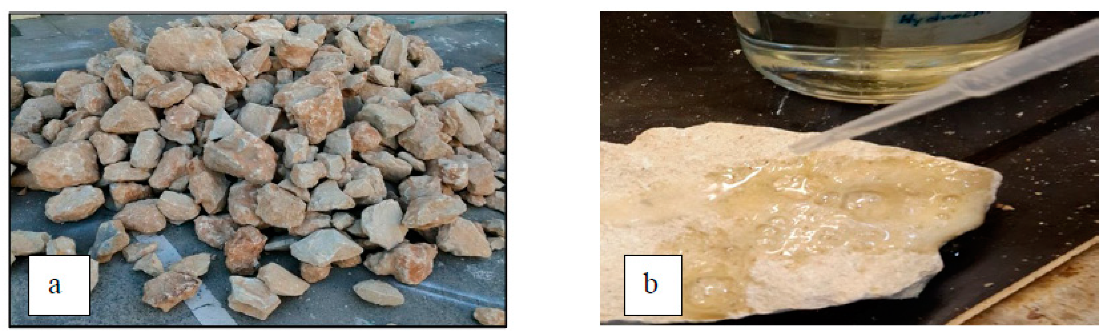
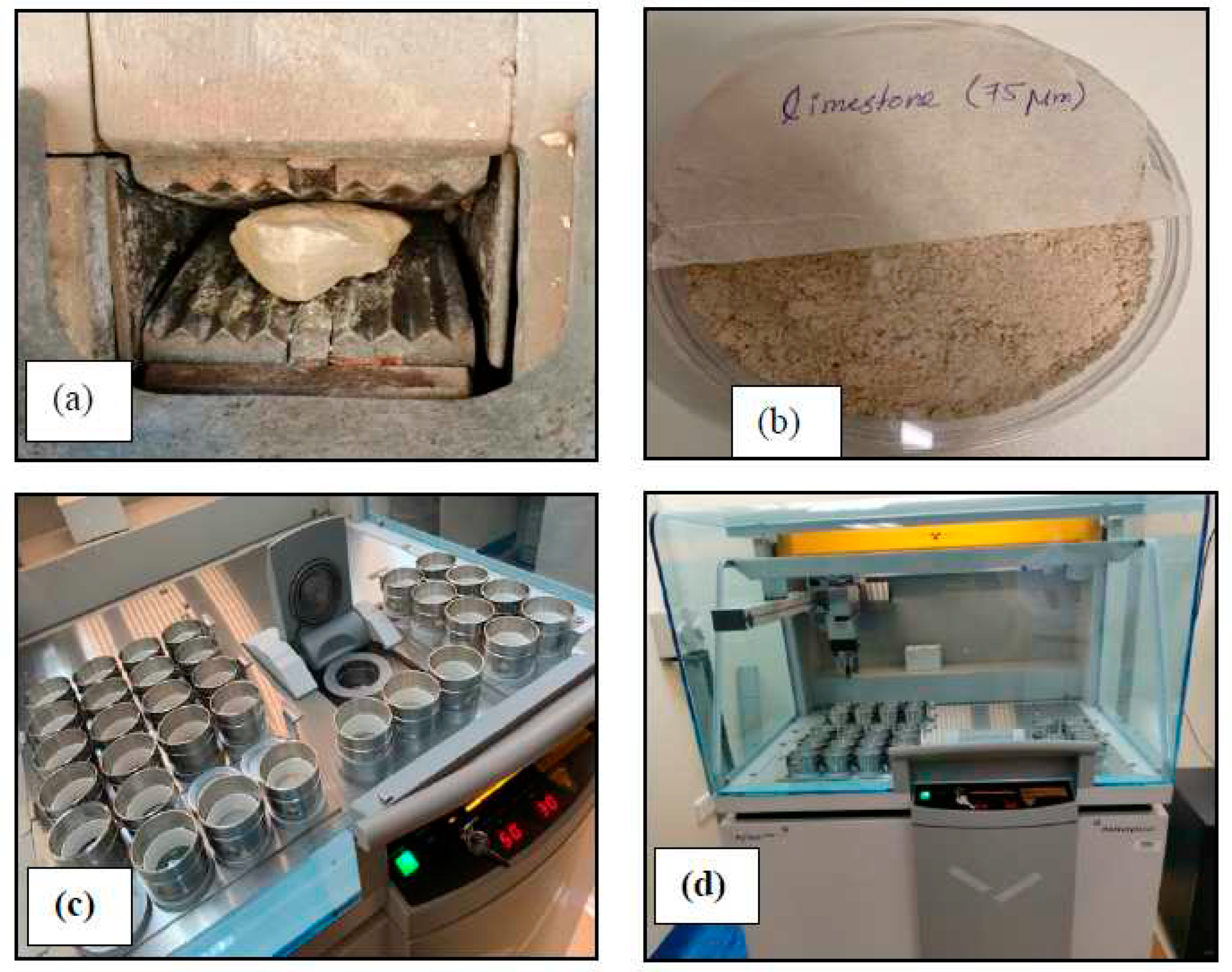
Figure 1.
a) Limestone, b) Limestone Reaction with HCl.
Figure 2.
Photographs of (a) Crushing stone sample; (b) Sieved sample; (c and d) XRF Test.
The uniaxial compressive strength of the limestone was determined by extracting 10 cubes with dimensions of approximately 70.7 × 70.7 × 70.7 mm from random limestone samples (see Fig. 3). The uniaxial compressive strength was determined as per ASTM D7012, 2004 [21]. It was found to be 57 MPa as an average value from the 10 samples.
The water absorption of the stone was determined according to ASTM D6473, 2010 [22] standard procedures. The stones were weighed after they had been soaked in water; they were then oven dried and weighed. The water absorption was found to be 2.2%.
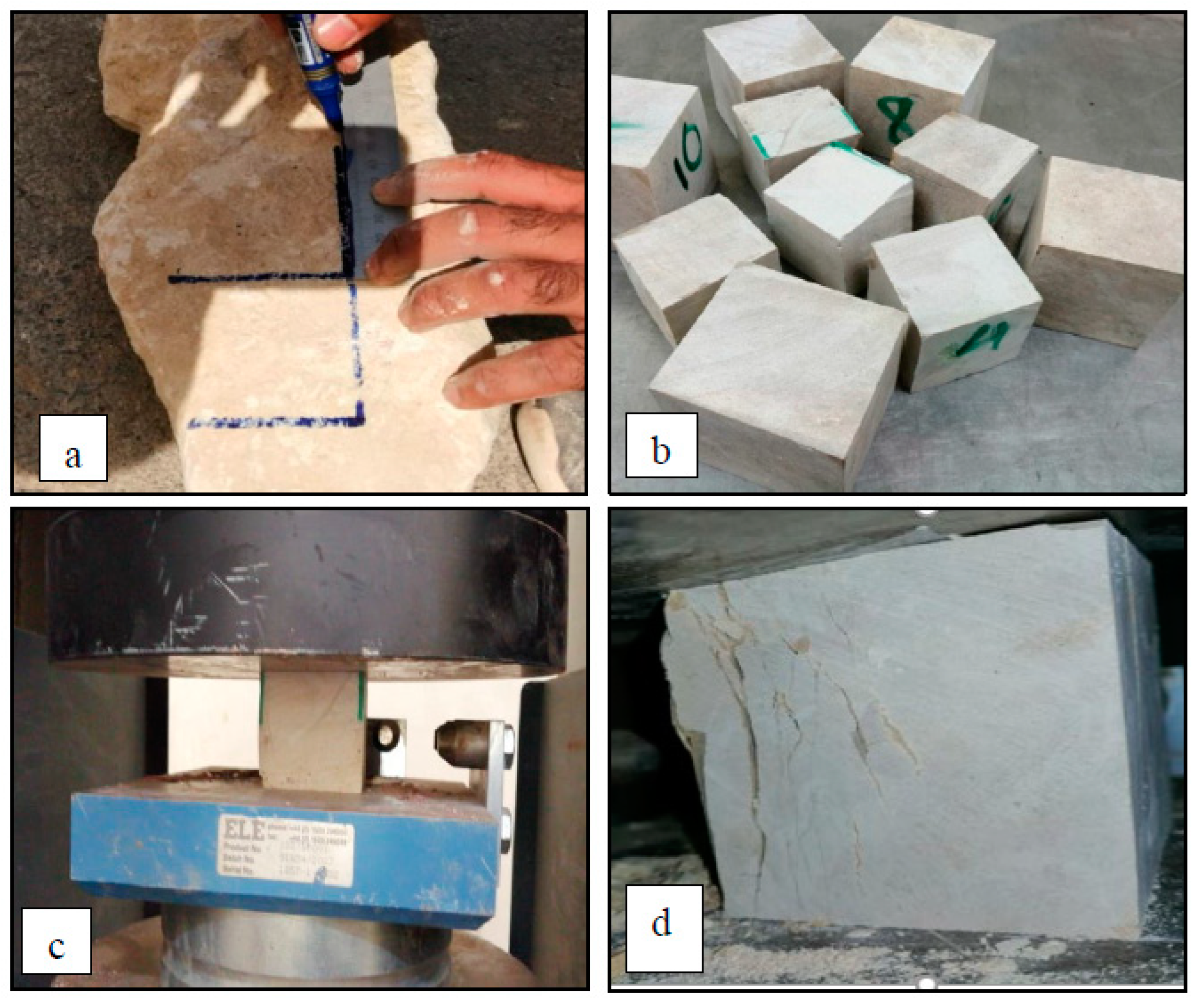
Figure 3.
Photographs of (a to b) cutting and extracting stone cube samples; (c to d) compressive Test and failure modes.
Figure 3.
Photographs of (a to b) cutting and extracting stone cube samples; (c to d) compressive Test and failure modes.
2.2. Sarooj
Sarooj was used in the construction of historical buildings for centuries. Previous studies [4, 16-18] have shown that the reactivity of sarooj is influenced by different factors, including physical, mechanical, chemical, and geotechnical properties.
The sarooj used in this study was donated by the Ministry of Heritage and Culture (MHC.. MHC maintenance department used sarooj extensively in the restoration work of historical buildings administered by the MHC. The chemical analysis of sarooj was obtained using a sample of sarooj with a passing sieve of 0.075 mm.according to tandard procedures to determine its chemical composition [23]. The results of the chemical analysis are summarized in Table 1. Three major components are considered to define sarooj as a pozzolanic material: SiO2, Al2O3, and Fe2O3. The total of the three components should be exceed 70%, according to ASTM Standard C618 [24]. However, in this sample, the total of the three components is approximately 52%. Therefore, the sarooj obtained from the MHCy cannot be considered as a natural pozzolana and may need the addition of some cement. The source of the clay used to produce sarooj and the calcination process affects the chemical composition of sarooj. In the traditional way of producing sarooj, it is difficult to control the calcination process [4].
2.3. Bed Joints Mortar
The cementing materials used in the mixtures were sarooj (passed a 600 µm sieve), ordinary portland cement (OPC), white cement and lime. Cement was added to enhance the binding properties of the mortar as recommended by Hago et al [18]. White and gray cement were used in the jointing mortar, while only white cement was used in the plaster (matrix) mortar to preserve the natural color of sarooj. Fine sand (passed a 600 µm sieve) was used in all mixtures to avoid shrinkage and micro-cracking. The matrix of the jointing mortar mix is sarooj, sand, ordinary portland cement, white cement, lime, and water with proportions by weight of 1: 0.4: 0.2: 0.2: 0.1: 0.5, respectively (see Fig. 4). This mix was selected from several mix trials based on workability and mechanical properties. Each mixture was cast into metal molds, producing three identical cubes with dimensions of 70.7 x 70.7 x 70.7 mm and prisms with dimensions of 100 x 100 x 500 mm. All mixtures were cured at a lab temperature of 22 ± 2 °C and a relative humidity of 20 - 30%. The slump for the mix was measured to be 35 mm. The presence of sarooj is the reason for the low slump, sarooj absorbs more water compared to sand. The uniaxial test of the cubes resulted in an average 28-day compressive strength of 11.39 MPa
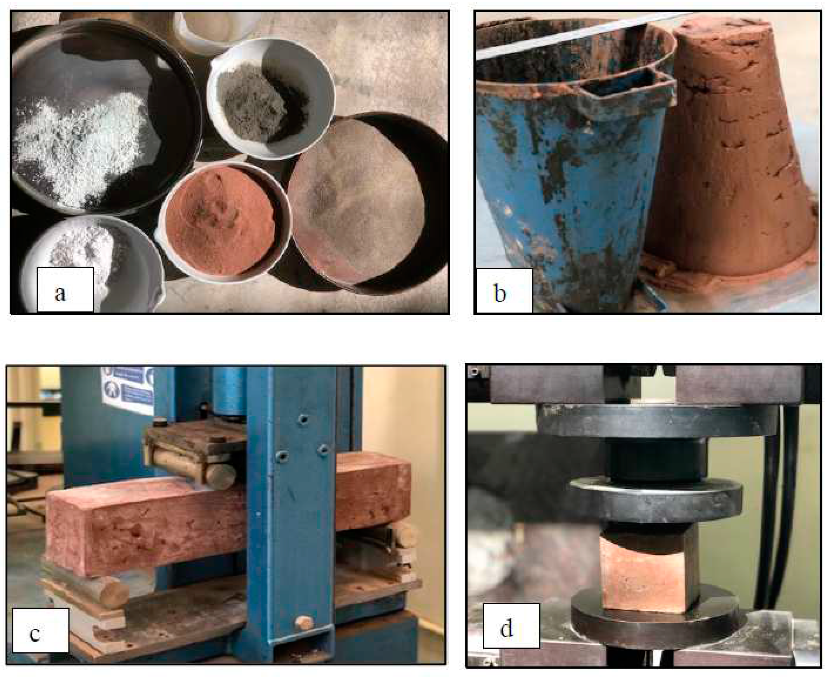
Figure 4.
Jointing Mortar (a) Materials used; (b) Slump test; (c) Flexural test; (d) Compression test.
Figure 4.
Jointing Mortar (a) Materials used; (b) Slump test; (c) Flexural test; (d) Compression test.
2.4. Plaster Mortar
The plaster mortar mix is sarooj, sand, white cement, lime, and water with proportions by weight of 1: 0.5: 0.5: 0.375: 0.75, respectively (see Fig. 4). The slump for the mix was measured to be 34 mm. This mix was selected from several mix trials based on workability and mechanical properties. A similar procedure as used in the jointing mortar was adopted in casting and curing the specimens. The recommendations by Hago et al [18] was adopted for the selected optimum design mix ratios of sarooj, sand, and cement to produce the maximum strength. The uniaxial test of the cubes resulted in an average 28-day compressive strength and tensile strengths of 11.67 MPa and 1.7 MPa, respectively.
2.5. Basalt Textile
A basalt bi-directional textile was used to strengthen the specimens. The textile has a roving dimension of 1.6 mm wide by 0.5 mm thick in the longitudinal direction. and a roving dimension of 0.6 mm wide by 0.5 mm thick in the transverse direction. The grid spacing between the rovings is about 10 mm in both directions (Fig.5a).
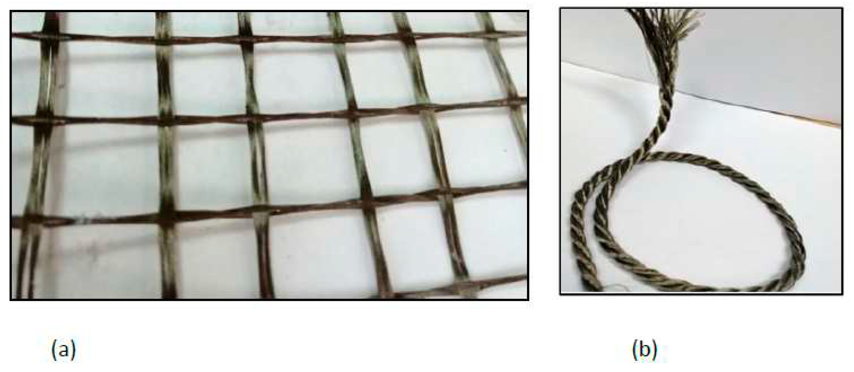
Figure 5.
a) Basalt Fiber Textile, b) Basalt Rope.
The uniaxial tensile strength was determined according to ASTM D5034 - 09(2013) [25]. The textile tensile test samples were cut to be 500 mm long and 100 mm wide as shown in Fig. 6. In addition, composite coupon specimens consisting of one layer of textile fibers embedded in sarooj mortar was also tested to determine uniaxial tensile strength as shown in Fig. 7. First, a 500-mm long, 100-mm wide, and 22-mm thick panel was cast on a flat wooden mould. Once one layer of mortar was cast and smoothened, one ply of the textile grid was applied. Then, the cover layer of mortar was cast to fill the mould as shown in Fig. 7. The composite specimens were cured in room temperature for 28 days. A uniaxial load was monotonically applied in a displacement-controlled routine . Metal plates of approximately 2.5 mm thickness were attached to the ends of test specimens using grout to avoid stress concentration beneath the clamp. Fig. 8 shows the tensile test results of the textile and the composite specimens. The load versus the displacement of the textile fiber shows a linear curve until failure, while the curve for the composite shows two characteristic phases: an initial steep curve representing the non-cracked section phase and then a reduced-slope curve corresponding to the cracked section phase. The failure of the textile specimens was characterized by the successive rupture of the weft yarns. The rupture occurred randomly, as shown in Fig. 6d. The failure of the composite specimens was due to the complete rupture of the specimen as shown in Fig. 7e. The peak load for the fiber mesh reached an average of 1.7 kN, while the peak load for the composite specimens reached an average of 3.0 kN. The mortar matrix in the composite specimens helped in distributing the load among the textile fibers resulting in a higher load resistance.
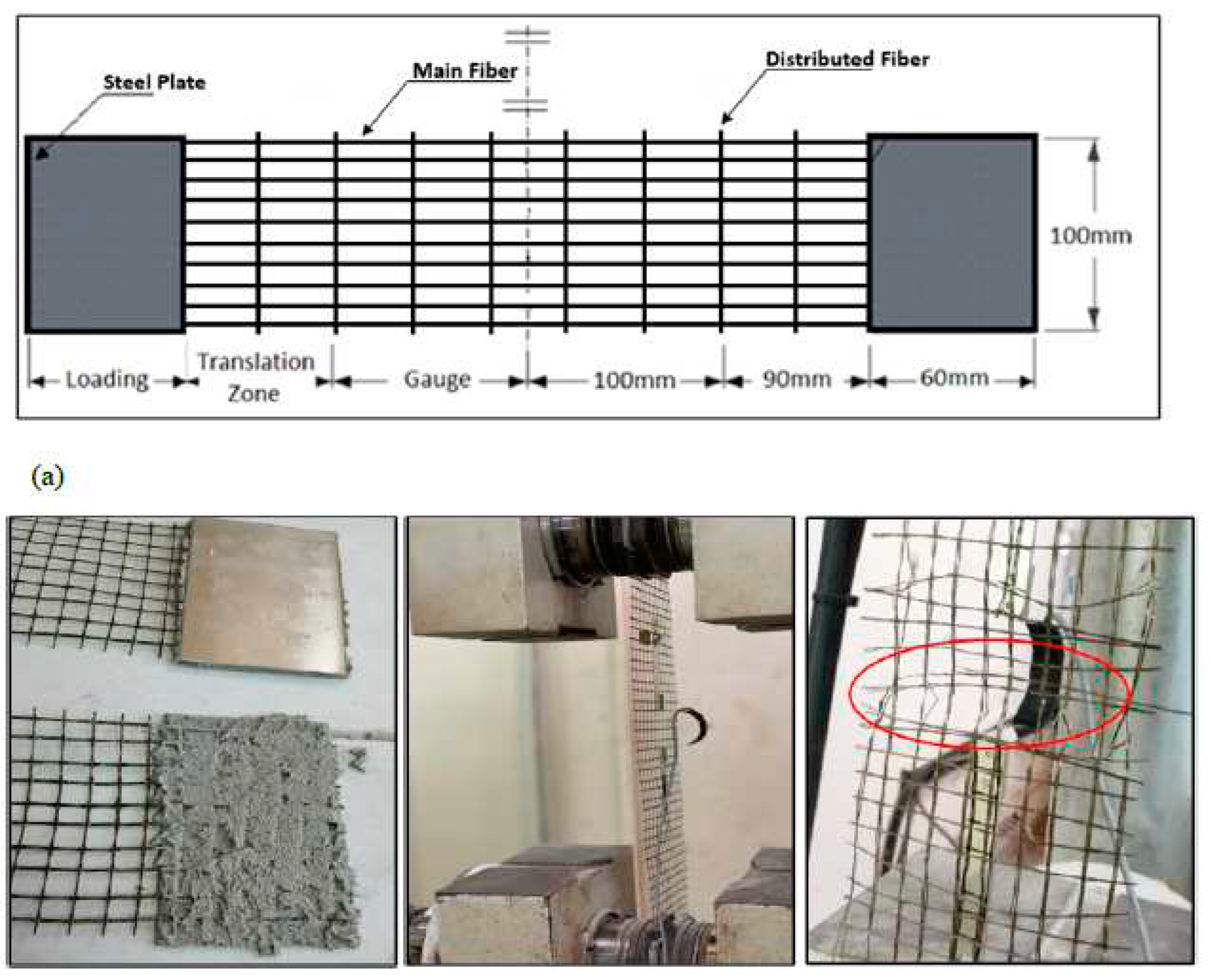
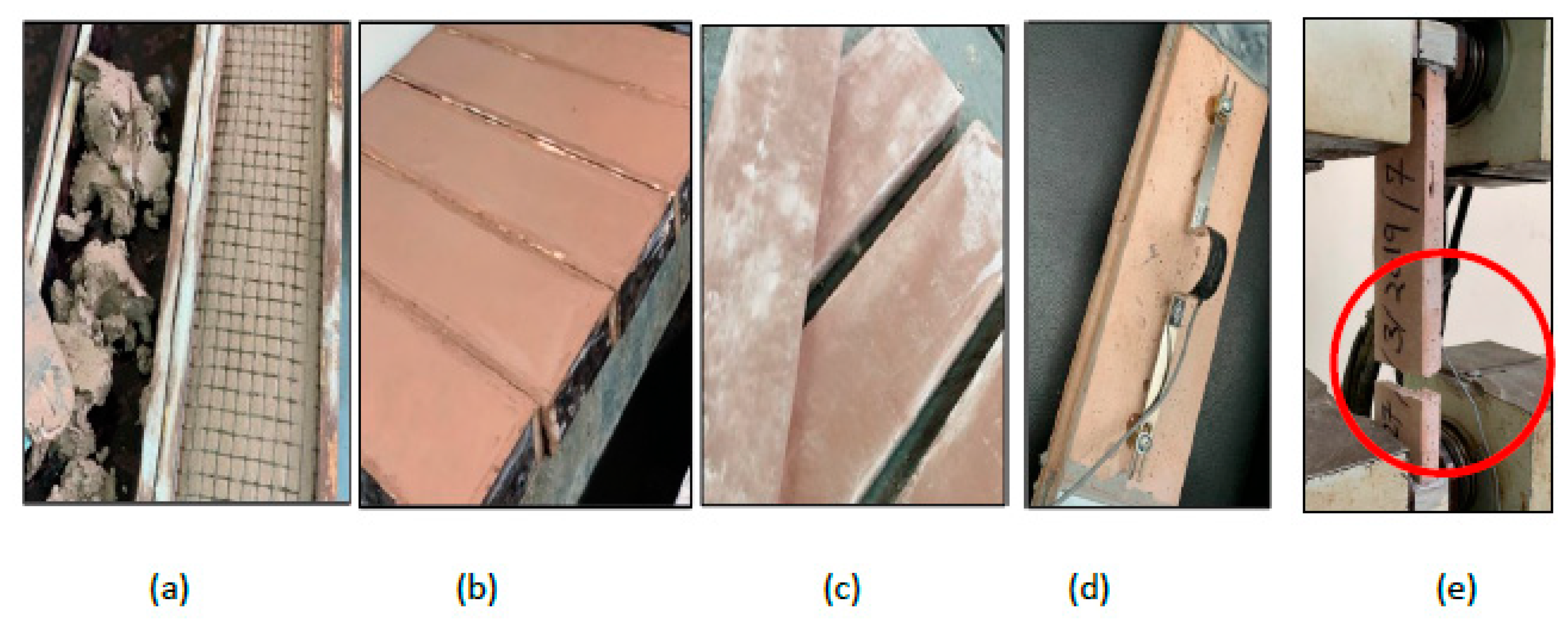
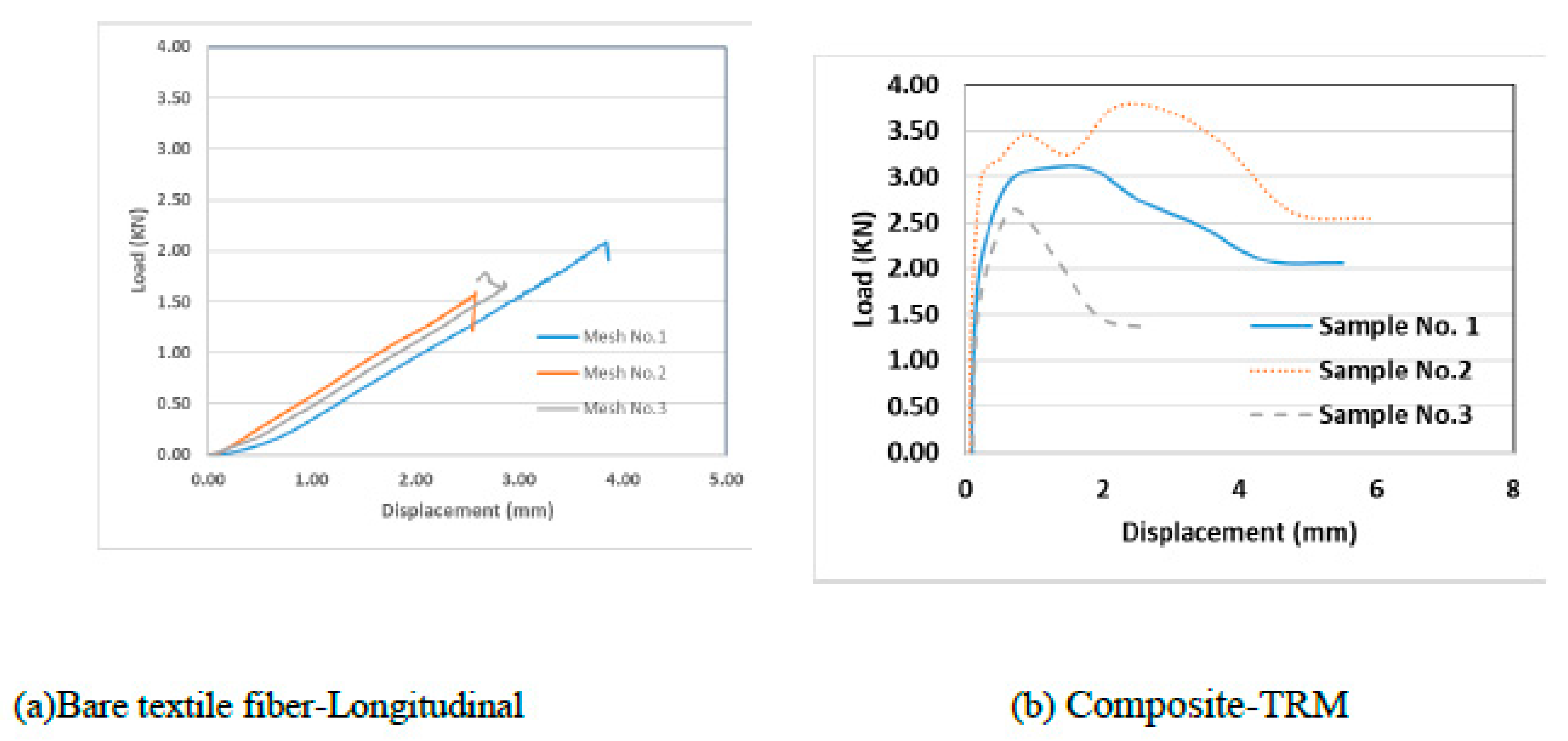
Figure 6.
Tensile Test Set up: (a) Sketch of Basalt Textile Grid Testing Sample.; (b) Preparing Sample with Steel Plate Ends; (c&d) Test Set up with LVDT.
Figure 6.
Tensile Test Set up: (a) Sketch of Basalt Textile Grid Testing Sample.; (b) Preparing Sample with Steel Plate Ends; (c&d) Test Set up with LVDT.
Figure 7.
Composite Samples (Basalt + mortar Tensile Test Set up: (a-c) Preparing Sample with Steel Plate Ends; (d) Test Set up with LVDT; (c) Failure Mode.
Figure 7.
Composite Samples (Basalt + mortar Tensile Test Set up: (a-c) Preparing Sample with Steel Plate Ends; (d) Test Set up with LVDT; (c) Failure Mode.
Figure 8.
Tensile Load vs. Elongation of tested Samples.
3. STONE MASONRY WALL CONSTRUCTION AND TEST SETUP
3.1. Compressive Strength of Masonry
Two specimens were constructed with dimensions of 500 mm long, 250 mm wide, and 1000 mm high as sketched in Fig. 9. They are unreinforced walls consisting of only stones and jointing mortar. These walls were constructed to evaluate the compressive strength of the stone masonry. The wall specimens were tested under compression (monotonic load) using a 4000 kN universal testing machine as illustrated in Fig. 9. The load was applied by a hydraulic cylinder, which is computer controlled at a rate of 0.6 kN/s, and was measured using the machine’s load cell, and displacement was measured via the displacement transducer.. A typical load displacement curve is shown in Fig. 10. Initially, the curve looks flat, as the load increases after some displacement. This is due to the neoprene (rubber) pad at the top of the wall at the point of the load application and due to the squeezing of the mortar layers until the stones pick up the load resistance and the load-displacement curve turns into a steep response, as illustrated in Fig. 10. The load then dropped once the peak load was reached, and the wall suffered from vertical cracks due to the effect of the Poisson's ratio (see Fig. 9). The wall then started to crumple at which point the test was stopped. The average compressive strength from the two walls specimens was 3.0 MPa.
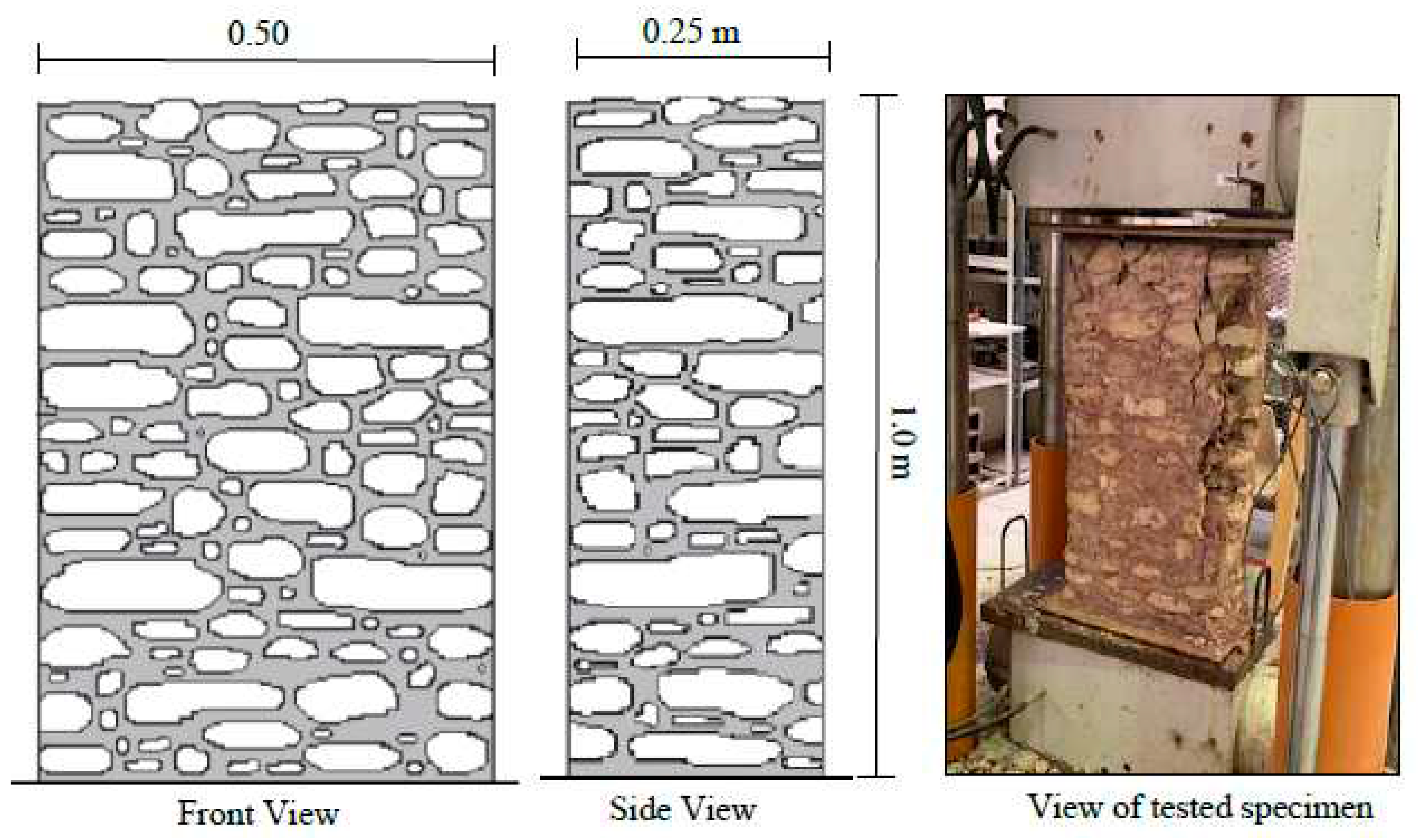
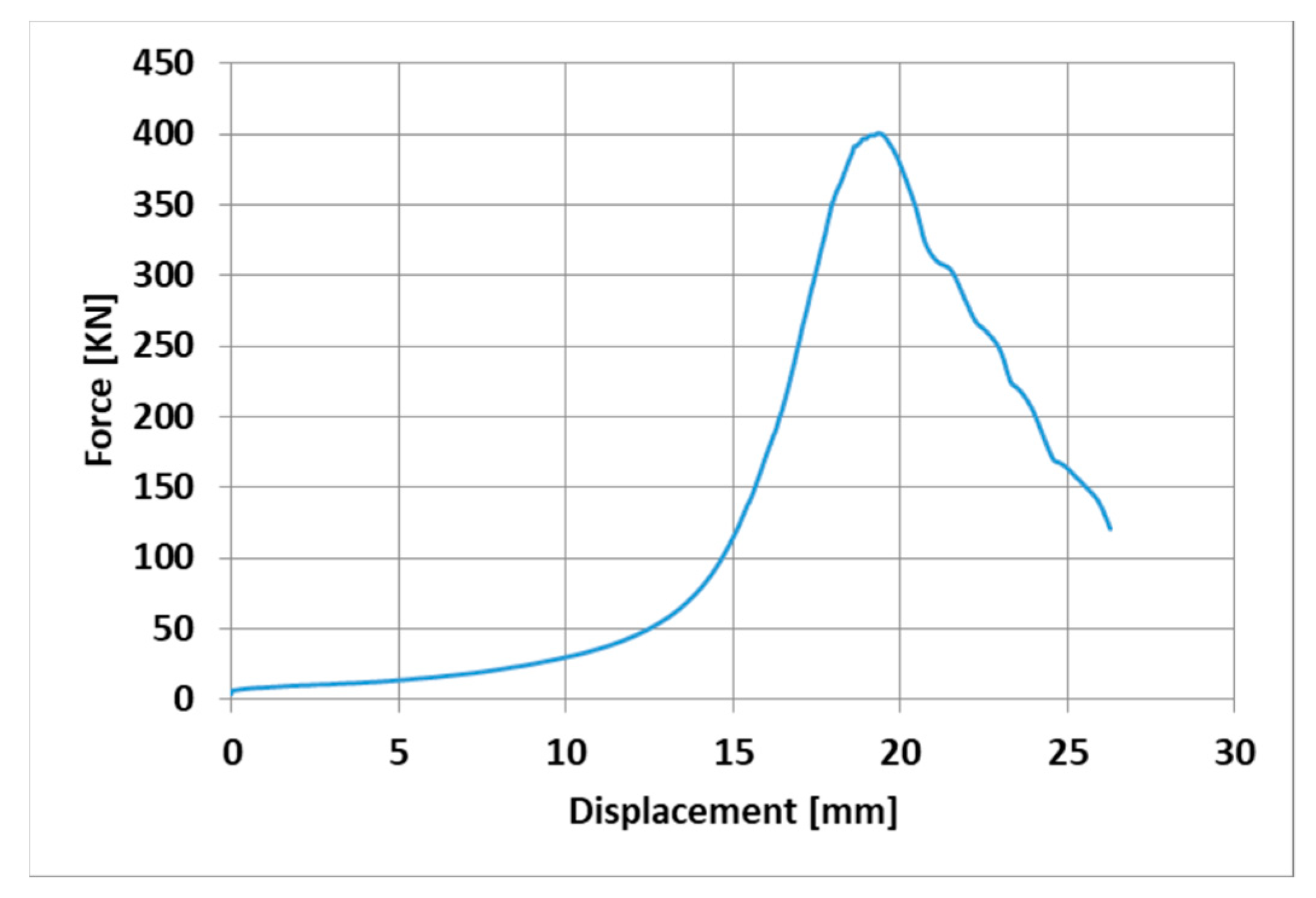
Figure 9.
Schematic and photographs of the Stone Masonry Wallets Specimens.
Figure 10.
Load vs displacement of the Stone Masonry Wallets Specimens.
3.2. Wall Specimens
The experimental program of supporting the stone wall specimens consisted of strengthening 2000 mm high, 1000 mm wide, and 350 mm thick stone walls with basalt TRM. This type of masonry is common in the masonry buildings of a large part of Oman and other countries. Four different walls were constructed to be tested for bending. One specimen was unreinforced (URM) and the other three specimens were reinforced with basalt textile mesh. The details of each wall are illustrated below, and the schematic illustration of the geometry of the walls is shown in Fig. 11.
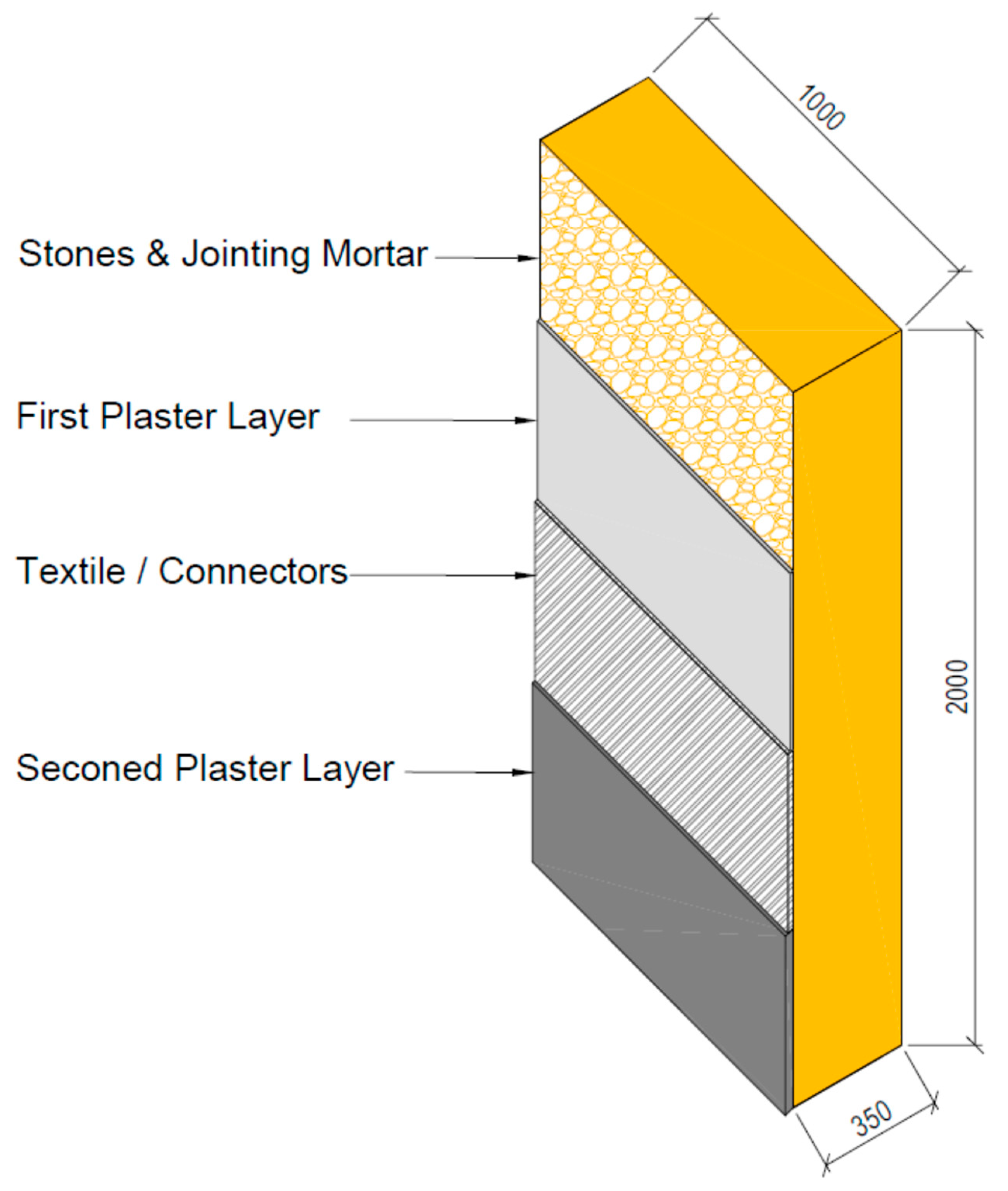
Figure 11.
Schematic illustration (units in mm) of strengthened wall specimens.
The samples were defined using identifier composed of three parts. The first part defined unreinforced masonry (U) or strengthened wall with the basalt mesh (R), and the latter identified the type of reinforcement (C= control wall without textile, T= wall with textile, TS= wall with textile and screws and TR= wall with textile and basalt ropes). The description of the wall specimens is listed in Table 2.
3.2.1. CASE I: Unreinforced Masonry Wall (UC)
This wall is considered the reference wall. It was constructed from stones and jointing mortar only. All walls were constructed by layering alternative layers of stone and mortar. Each wall was constructed until reaching a height of approximately 60 cm and was then left for the mortar to set (24 hours). The construction of the next layers was then resumed until reaching the full height of 2.0 meters. Fig. 12 shows photos of the construction of the unreinforced masonry wall specimens.
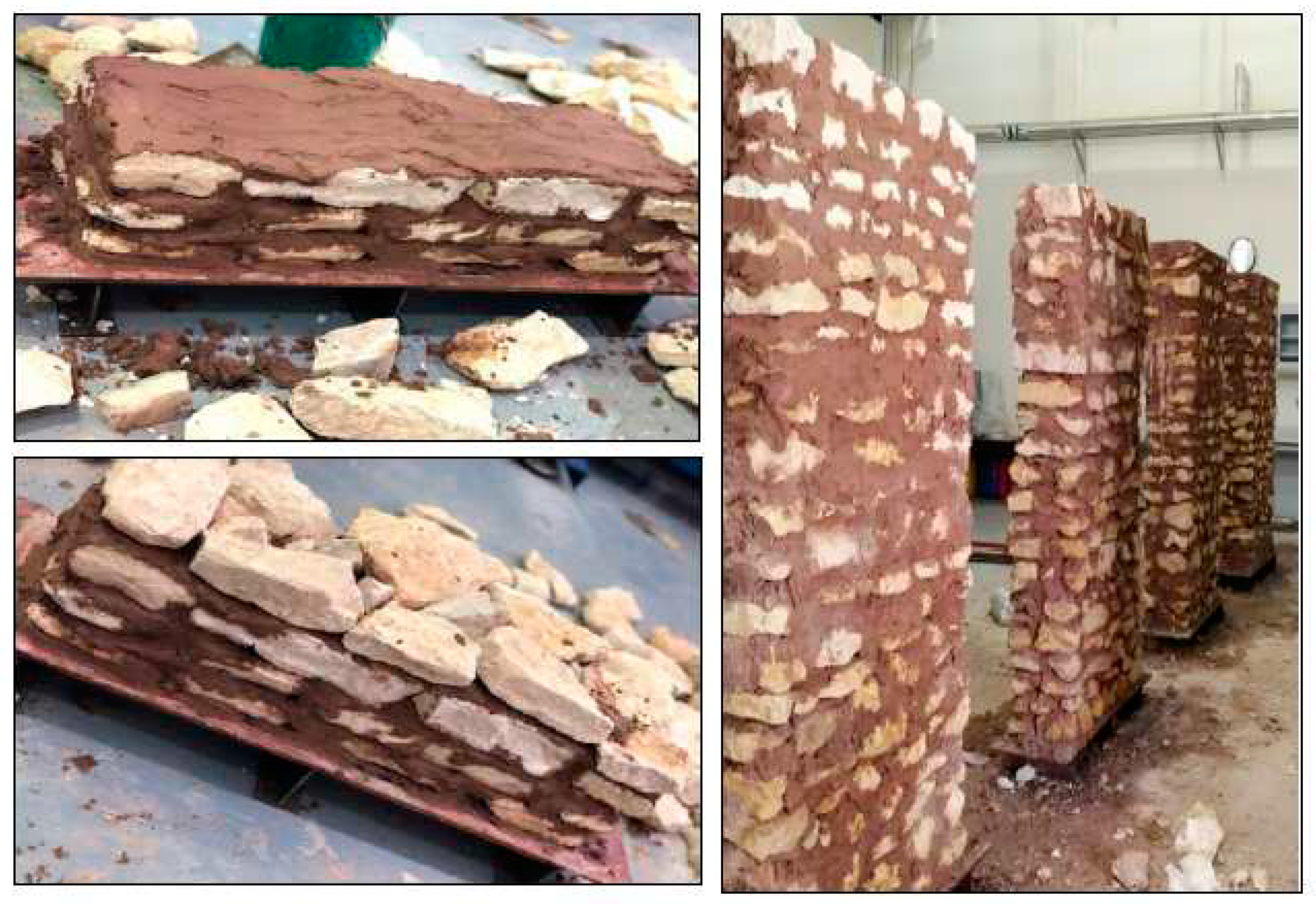
Figure 12.
Construction of stone masonry wall specimens.
3.2.2. CASE II: Wall Reinforced by Basalt Textile (RT)
The second wall was strengthened using basalt fiber textile. The first layer of sarooj mortar was applied on one face of the wall (tension face) to receive the textile mesh. The first layer of plaster varied between 2-3 cm to have a levelled face to stick the basalt mesh. The textile layer then was applied and pressed by hand to stick to the first layer of mortar. A second plaster layer of 0.5 cm thick was applied to cover the mesh. Photos of the wall construction are presented in Fig. 13.
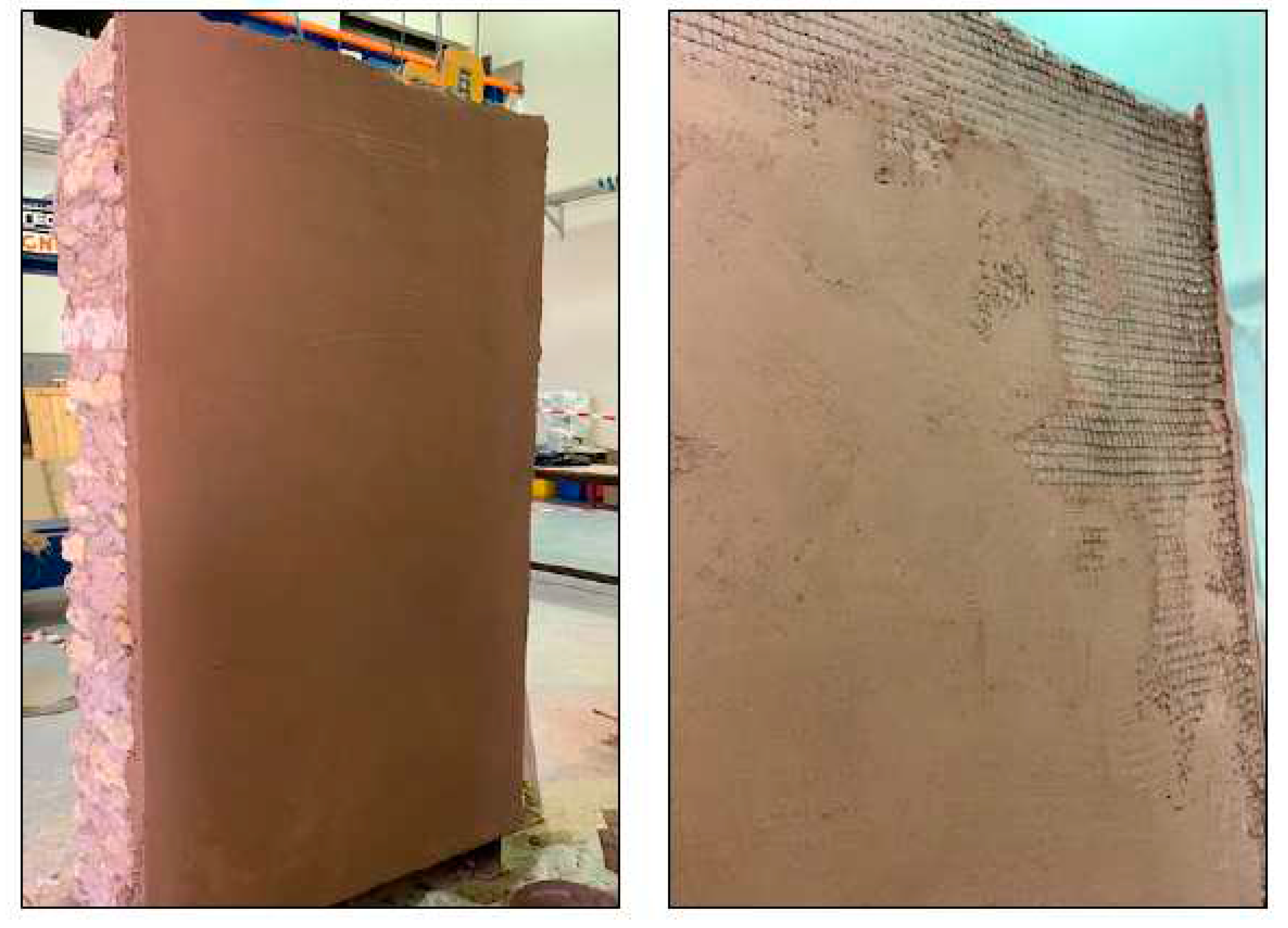
Figure 13.
Strengthening of first wall with one textile layer (RT).
3.2.3. CASE III: Wall Reinforced by Basalt Textile and Stainless Steel Screws and Washers (RTS)
The third wall was strengthened using a basalt mesh and stainless-steel screws and washers. Holes for the screws were first drilled into the walls. The distance between the holes was 20 cm in both directions, as shown in Fig. 14. Brass screws with plastic plugs were inserted inside the holes. The layer of sarooj mortar was then applied to receive the textile mesh. The textile layer was then applied and pressed by hand to stick to the first layer of mortar. After applying the basalt mesh, the brass screws were removed and reinserted again with steel washers to connect the mesh to the wall, as illustrated in Fig. 14. A second plaster layer of 0.5 cm thick was applied to cover the mesh.
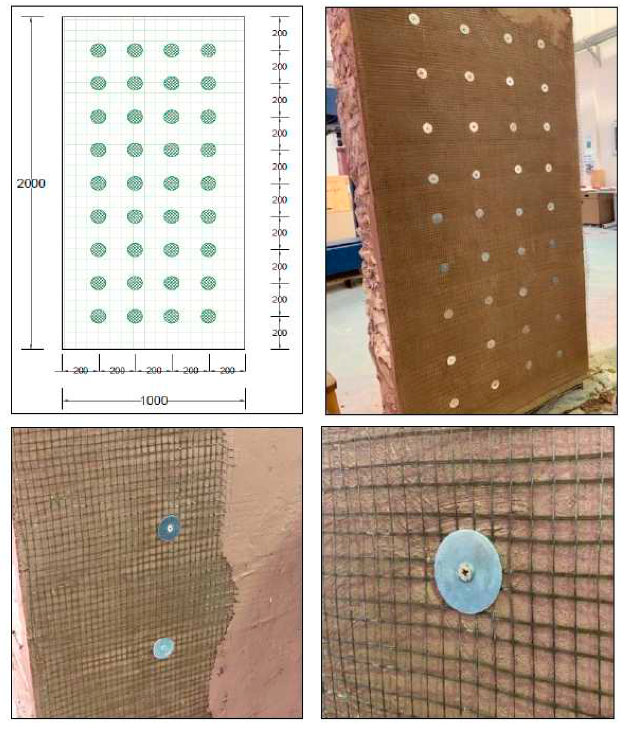
Figure 14.
Strengthening of the second wall with one textile layer + screws ((RTS).
3.2.4. CASE IV: Wall Reinforced by Basalt Mesh and Basalt Ropes (RTR)
The fourth wall was strengthened using a basalt mesh tied with basalt ropes. Holes for the ropes were first drilled into the walls. The distance between the holes was 20 cm in both directions. The ropes were inserted inside the wall and grouted with a high strength epoxy to fill the holes. The layer of sarooj mortar was then applied on the tension face of the wall to receive the textile. After applying the basalt mesh, basalt ropes were tied and overlapped horizontally using steel cable ties (see Fig. 15). Finally, A second plaster layer of 0.5 cm thick was applied to cover the mesh and left for curing.
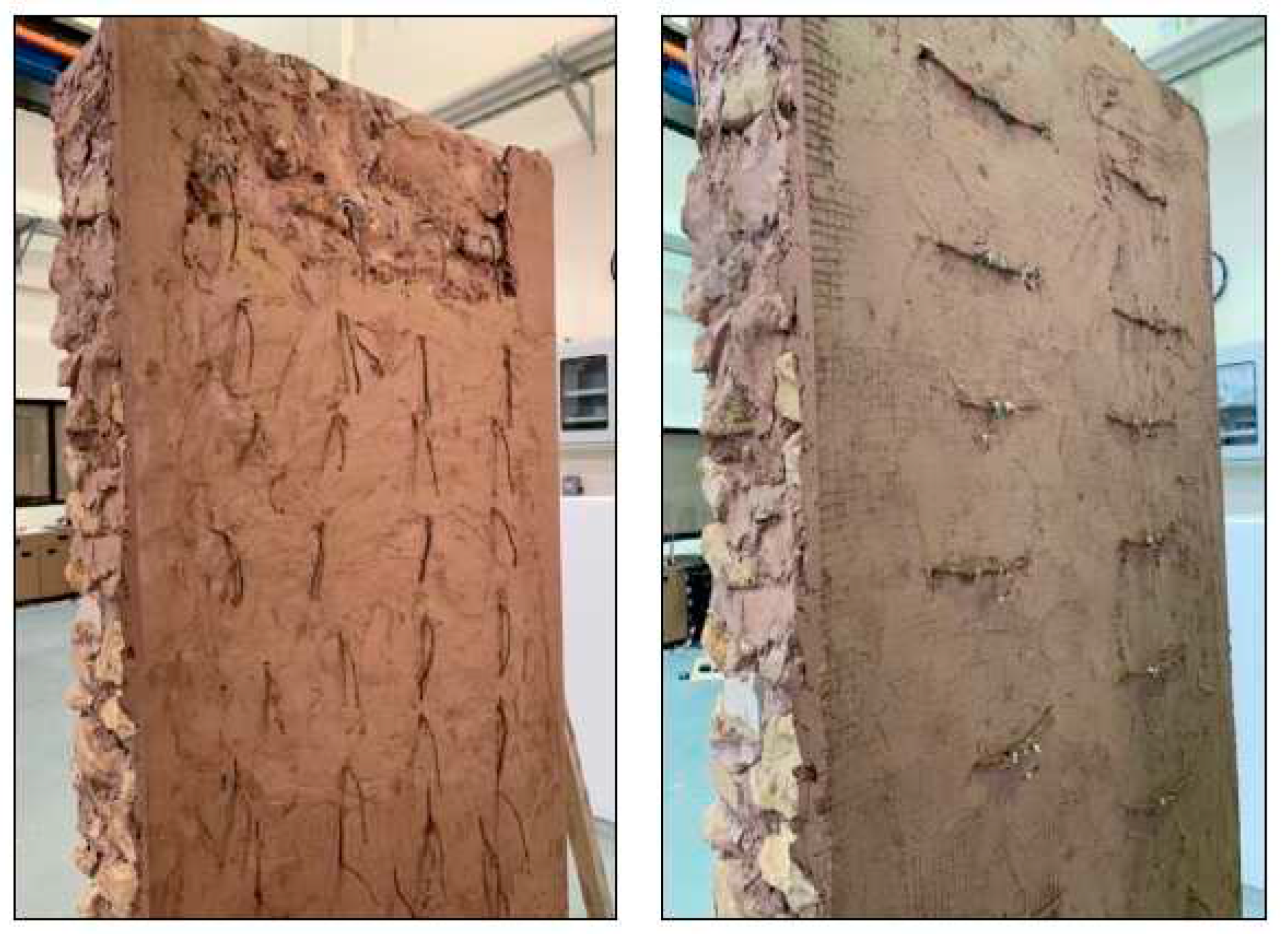
Figure 15.
Strengthening of the third wall with one textile layer + ropes (RTR).
4. TEST SET UP FOR WALLS BENDING TEST
All walls were tested for bending using four-point bending tests. The bending tests were performed by applying two forces laterally against the wall at the top and bottom third of the wall height. The reaction frame was designed and built for this research program, as illustrated in Fig. 16. To measure the deflections, displacement transducers were placed on the tension side of the wall face at the top, bottom third, and mid-point (see Fig. 16). Application of the force was load controlled until the first cracking; it was then switched to displacement control to prevent overturning and wall collapse.
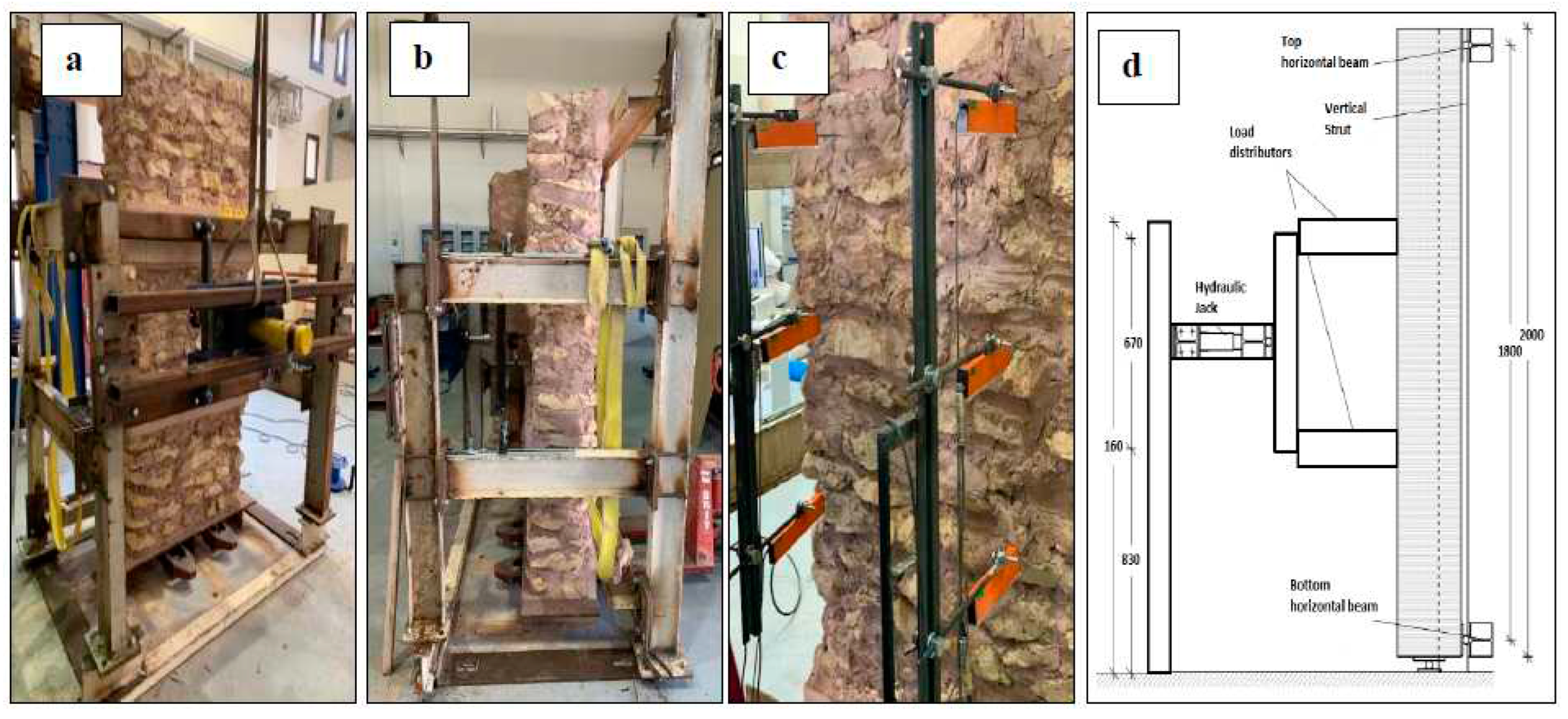
Figure 16.
Experimental Apparatus for Bending Tests: (a)&(b) Global View (c) LVDTs and (d) Vertical Section.
Figure 16.
Experimental Apparatus for Bending Tests: (a)&(b) Global View (c) LVDTs and (d) Vertical Section.
5. BENDING TEST RESULTS OF THE STONE MASONRY WALLS
The load versus out-of-plane mid-span deflections for all wall specimens are shown in Fig. 17. For the control wall (UC), the behavior shows a linear behavior, and no cracks were observed on the wall up to 6 kN load, as the specimen remained undamaged. At this stage, the wall started to crack on the tension side, at about the center of the top third of the wall, and this was followed by other cracks in the bottom of the wall (see Fig. 18a). The first crack opened at the top of the wall, since the compressive weight force of the wall is the smallest at the top and highest at the bottom, where it might counteract (due to the normal compression force of the weight) the tensile stress from bending. The crack affected, for the most, the masonry mortar interface and involved the whole masonry thickness. The slope of the load versus the mid-span deflection shows the decreased stiffness beyond the cracking load. At a maximum failure load of 9.15 kN, the top one-third point exhibited the largest displacement of 1.93 mm. Fig. 19 shows the displacement profile along the wall height. The wall displacements are maximum at the top third height of the wall where the cracks were first observed.
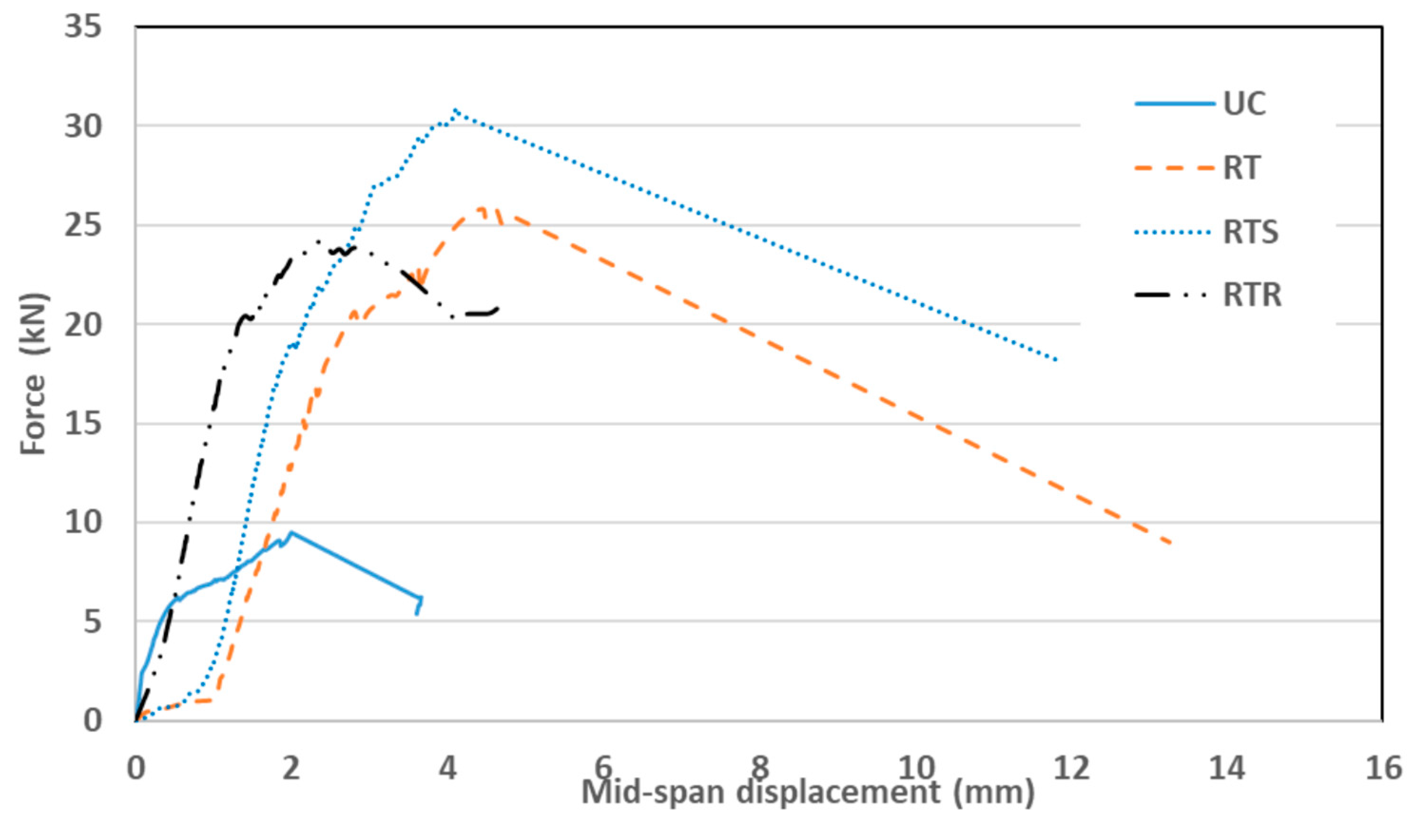
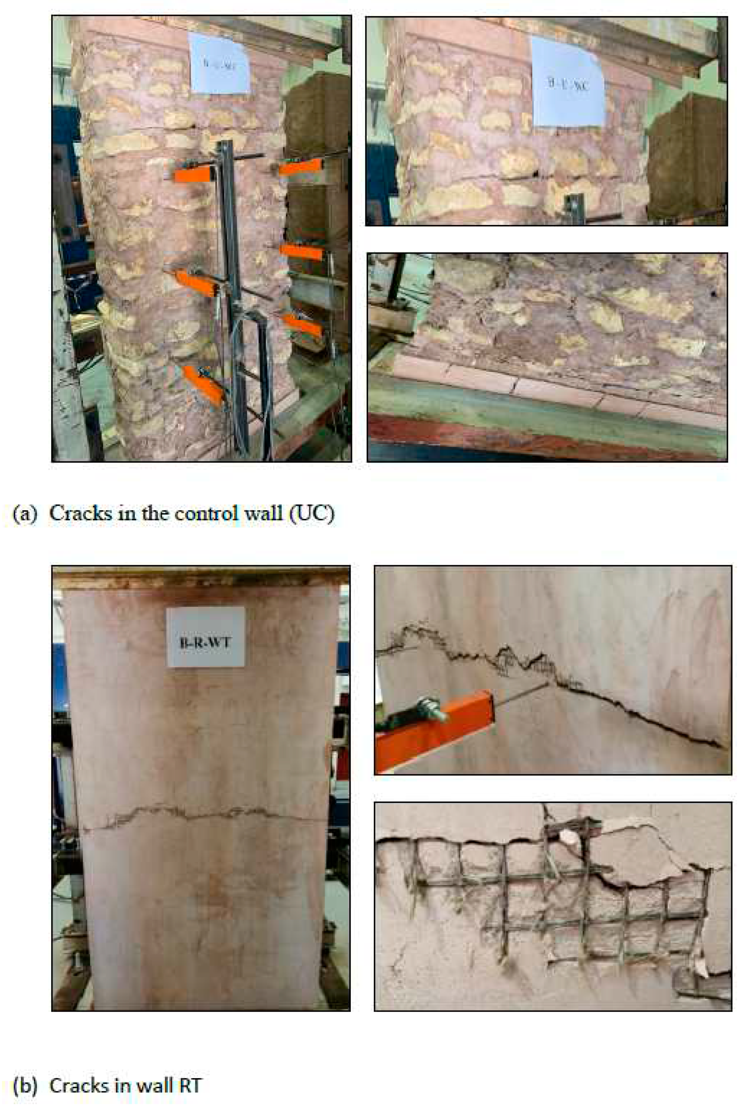
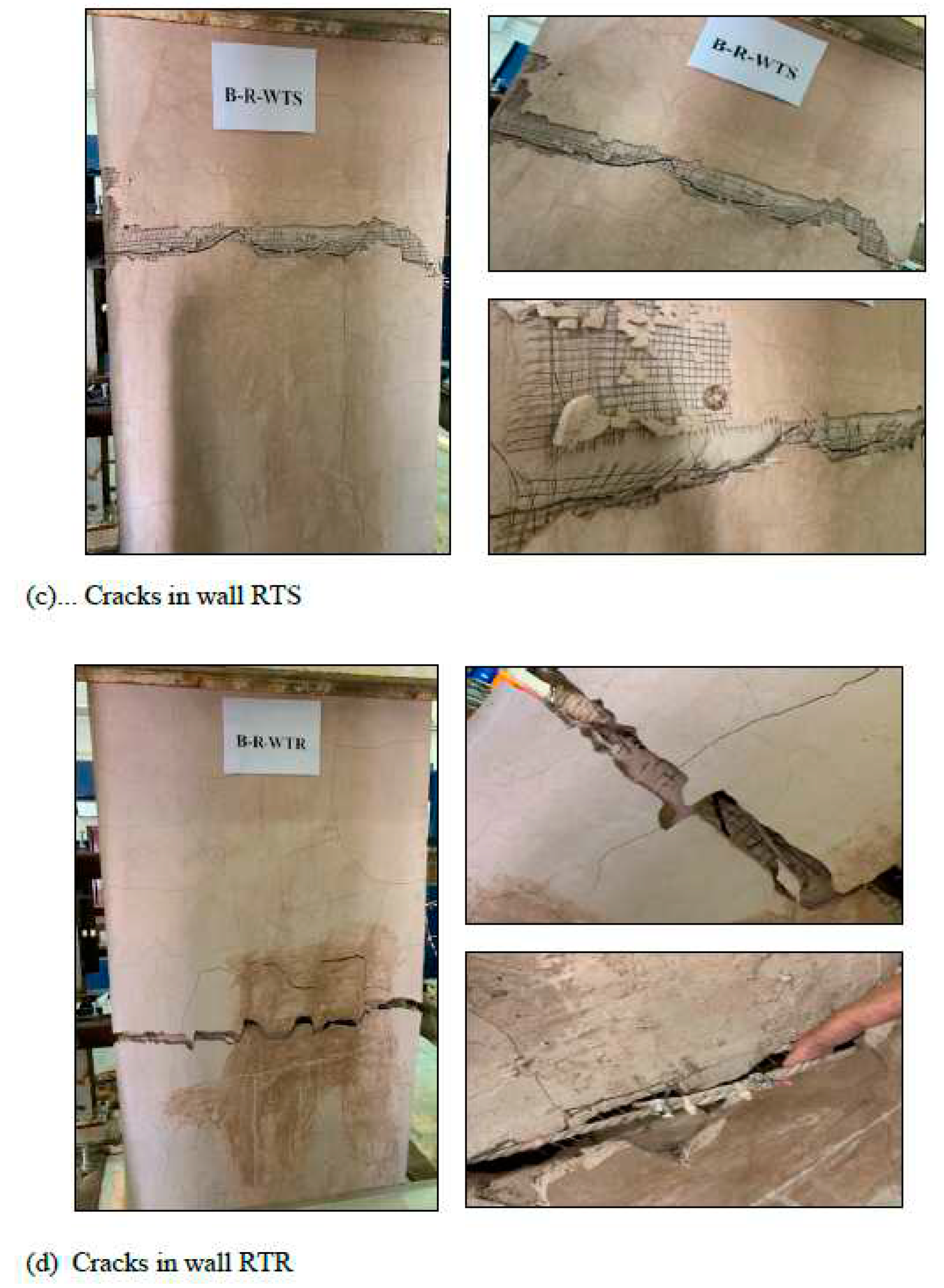
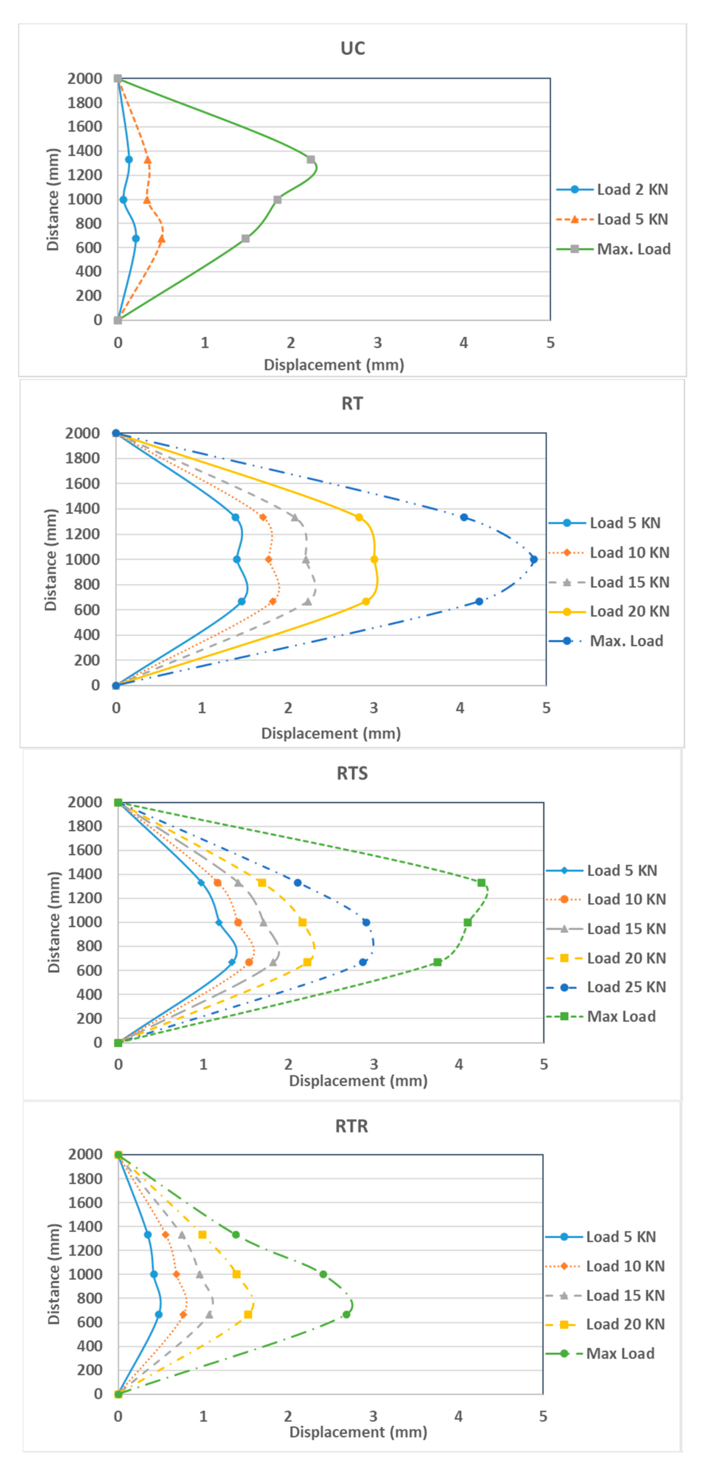
Figure 17.
Load vs midspan displacement all walls.
Figure 18.
Failure modes and crack pattern.
Figure 19.
Displacement profile along the wall height.
30
The wall strengthening with one layer of textile (RT) shows, at the initial stage, a relatively linear behavior and no cracks were observed on the wall up to 20 kN load. Beyond this load, a horizontal crack started to develop in the mortar at about the mid-height point of the tension side of the wall (see Fig. 18b). Consequently, basalt textiles started to bear tension loads leading to a continuous widening in the crack width until failure. The walls failed after the rupture of the textile layer. The crack affected the masonry mortar interface and involved the whole masonry thickness. At the maximum failure load of 25.8 kN, the mid-point exhibited a displacement of 4.61 mm. Fig. 19 shows the displacement profile along the wall height. The wall displacement was maximum at mid-height of the wall. The test was stopped after reaching the maximum load to prevent wall overturning collapse. The main crack (where the textile fibers ruptured) involved the whole masonry thickness, and no debonding was observed between the mesh and substrate.
The second strengthened wall (RTS) was strengthened with one layer of textile augmented with mechanical connecters consisting of brass screws and washers. Similar response is observed of linear behavior before cracking at 18 kN at which cracks developed at about the center of the top third of the wall. A small shift in the load versus the mid-span deflection curve was observed due to the initiation of the crack with a minor change in the slope of the curve, indicating a minor stiffness decrease (Fig. 17). This wall performed the best in terms of the maximum load attained compared to the reference wall. At the maximum failure load of 30.9 kN, the mid-point exhibited a displacement of 4.1 mm. Fig. 19 shows the displacement profile along the wall height. The wall displacement was maximum at the top third of the wall. The effect of the screws’ mechanical anchoring and the stabilizing of the textile mesh obviously augmented the bond strength provided by the mortar. The disadvantage was the extra work required to install the screws. The main crack (where the textile fibers ruptured) involved the whole masonry thickness, and there was no debonding observed between the mesh, substrate, and screws, as shown in Fig. 18c
The last strengthened wall (RTR) was strengthened with one layer of textile augmented with 5-mm basalt rope tied around the textile layer in a horizontal direction at 200-mm intervals. The load versus mid-span deflection is shown in Fig. 17. Similar behavior was observed as in the other strengthened walls of relatively linear behavior until the first crack appeared at a load of 20 kN corresponding to the mid-span deflection of 1.48 mm. At the maximum failure load of 24.2 kN, the bottom one-third point exhibited the largest displacement of 2.415 mm. Fig. 19 shows the displacement profile for the wall height. Using ropes was a laborious job and turned out to be the least effective among the strengthened walls in with respect to the maximum resisting load as well as deformation. At the end of the test, it was observed that the tying ropes were loose and relaxed (see Fig. 18d), which seems ineffective. It might have disturbed the plaster layer while tying the ropes and might have caused local pockets of loose mortar layers around the rope area, which in turn affected the overall textile layer. As evidence, this wall even performed less well than the wall strengthened with textile only (see Fig. 20).
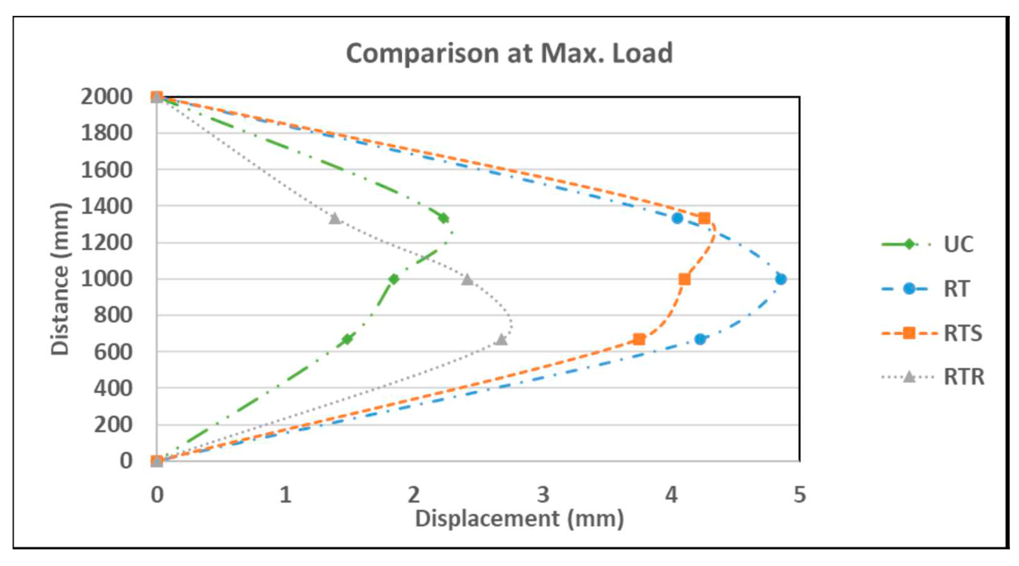
Figure 20.
Displacement profile along the wall height at max. load for all walls.
The test results are summarized in Table 3. They show that the gain in moment capacity increased (compared to the control wall UC) 2.78, 3.33, and 2.6 times (or 178%, 233%, and 160%) for walls RT, RTS, and RTR, respectively.
6. ESTIMATNG THE MOMENT CAPACITY OF THE STRENGTHENEND WALLS
The theoretical moment capacity of masonry walls retrofitted by TRM can beestimated using analytical models from the available literature [26-28]. For the unreinforced control specimen, equation (1) can be used to calcculate the failure moment capacity:
where, ft is the tensile strength of mortar, and b and h are the width and thickness of the wall, respectively.
For strengthened wall specimens with a failure due to textile rupture, which is the case in this study, the flexural model proposed in the literature based on the assumptions that plane-section remains plane after bending, tensile strength of masonry is neglected, and the equilibrium condition of section forces is satisfied [27]. As shown in Fig. 21, the moment capacity can be estimated as follows:
where, t, b, and x are the thickness of the TRM composite layer, the width of cross section, and the compressive depth of masonry, respectively. fm is the compressive strength of masonry, α and β are the equivalent rectangular stress coefficient and stress block depth coefficient, respectively. The values of α and β are taken to be as 0.67 and 0.75 as recommended by Deng et al. [28]. The value of T was determined from the composite coupons presented earlier. The theoretical values of moment capacity for the strengthened wall are listed in Table 3. Equation 3 reasonably estimates the moment capacity for the wall with screws (RTS) and slightly overestimates the other two walls. This is due to the heterogeneous nature of the stone masonry, which has more variations compared to brick masonry. However, this model may be used to provide a rough estimate of the moment capacity due to its simplicity.
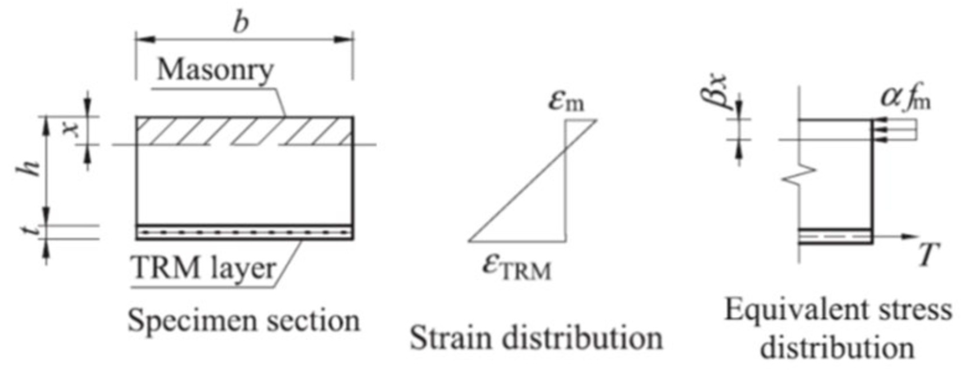
Figure 21.
Theoretical ultimate state stresses at flexural failure of strengthened specimens [27].
Figure 21.
Theoretical ultimate state stresses at flexural failure of strengthened specimens [27].
7. CONCLUSIONS
This research investigated the use of TRM technique to strengthen historical stone masonry structures. Chemical and physical tests were performed to characterize the materials used in the study: limestone, sarooj, and basalt textile. Then a TRM was used to strengthen masonry walls for out-of-plane bending. One masonry wall was unreinforced, and the rest were reinforced with textile fibers. On the basis of the presented experimental work, the following conclusions are made:
- Sarooj mortar is compatible with stone masonry structures based on the investigated physical and chemical properties of the stones and sarooj. The compatibility of the strengthening system is vital in persevering historical structures.
- Unreinforced masonry specimen (UC) showed sudden brittle failure due to the opening of a single horizontal crack.
- All reinforced specimens exhibited a relatively ductile behavior before failure compared to the URM wall with increase in the maximum deflection before failure by 130%,106%, and 21% for walls RT, RTS, and RTR, respectively.
- All strengthened specimens failed due to textile rupture when the basalt textile reached its ultimate strain.
- The strengthened specimens resisted an out-of-plane bending moments of about 2.5 to 3 times that of the unreinforced specimen (a 160-233% increase). The strengthening method using textile mesh in addition to screws and washers (RTS) was the most efficient method.
Author Contributions
Conceptualization, Abdullah Al-Saidy; Validation, Sherif El-Gamal and Kazi Abu Sohail; Investigation, Manal Al-Busaidi.; Writing—original draft, Abdullah Al-Saidy; Writing—review & editing, Sherif El-Gamal and Kazi Abu Sohail. All authors have read and agreed to the published version of the manuscript.
Funding
This research was funded by Sultan Qaboos University through an internal grant # IG/ENG/CAED/17/01.
Data Availability Statement
Not applicable.
Acknowledgments
This research was funded by Sultan Qaboos University through an internal grant # IG/ENG/CAED/17/01 which is highly acknowledged.
Conflicts of Interest
The authors declare no conflict of interest.
References
- Maccarini, H., Vasconcelos, G., Rodrigues, H., Ortega, J., & Lourenço, P. B. (2018). Out-of-plane behavior of stone masonry walls: Experimental and numerical analysis. Construction and Building Materials, 179, 430–452. [CrossRef]
- Hegazy, S. M. (2015). Conservation of historical buildings–The Omani-French museum as a case study. HBRC Journal, 11(2), 264–274. [CrossRef]
- Bernat-Maso E., Escrig C., Aranha C., & Gil L. (2014). Experimental assessment of textile reinforced sprayed mortar. Construction and Building Materials 50, 226-236. [CrossRef]
- Al-Rawas A., and Hago A. (2006). Evaluation of field and laboratory produced burnt clay pozzolans. Applied Clay Science, 31, p. 29–35. [CrossRef]
- Ehsani, M. R., Saadatmanesh, H., and Al-Saidy, A. (1997). Shear behavior of URM retrofitted with FRP overlays. Journal of Composites. for Construction, 2(1), 17–25. [CrossRef]
- Triantafillou T. (1998). Strengthening of masonry structures using epoxy-bonded FRP laminates. Journal of Composites for Construction, 2, 96–104.
- Kouris, L. A. S., & Triantafillou, T. C. (2018). State-of-the-art on strengthening of masonry structures with textile reinforced mortar (TRM). Construction and Building Materials, 188, 1221–1233. [CrossRef]
- Triantafillou, T. C., Papanicolaou, C. G., Zissimopoulos, P., & Laourdekis, T. (2006). Concrete confinement with textile-reinforced mortar jackets. ACI Materials Journal, 103(1), 28. [CrossRef]
- Babatunde, S. A. (2017). Review of strengthening techniques for masonry using fiber reinforced polymers. Composite Structures, 161, 246–255. [CrossRef]
- Kolsch, H. (1998). Carbon fiber cement matrix (CFCM) overlay system for masonry strengthening. Journal of Composites for Construction, 2, 105–109.
- Papanicolaou C., Triantafillou T., & Lekka, M. (2011). Externally bonded grids as strengthening and seismic retrofitting materials for masonry panels. Construction and Building Materials,25, 504–514. [CrossRef]
- Pinho F., Luco V., & Baiao, M. (2014). Rubble stone masonry walls strengthened by three-dimensional steel ties and textile reinforced mortar render under compression. International Journal of Architectural Heritage, 8(5), 670–689. [CrossRef]
- Harajli, M., ElKhatib, H., & San-Jose, J. T. (2010). Static and cyclic out-of-plane response of masonry walls strengthened using textile-mortar system. Journal of Materials in Civil Engineering, 22(11), 1171-1180. [CrossRef]
- Papanicolaou, C. G., Triantafillou, T. C., Papathanasiou, M., & Karlos, K. (2008). Textile reinforced mortar (TRM) versus FRP as strengthening material of URM walls: Out-of-plane cyclic loading. Materials and Structures, 41(1), 143-157. [CrossRef]
- Padalu, P. K. V. R., Singh, Y., & Das, S. (2018). Efficacy of basalt fibre reinforced cement mortar composite for out-of-plane strengthening of unreinforced masonry. Construction and Building Materials, 191, 1172-1190. [CrossRef]
- Hago A., & Al-Rawas A. (1997). Properties of the Omani sarooj. Engineering Journal of University of Qatar, 10, p. 81-91. [CrossRef]
- Hago A., Al-Rawas A., & Al-Sidairi A. (2002). Effect of the fineness of artificial pozzolana (Sarooj) on the properties of lime-pozzolana mixes. Science and Technology, 7, 251-258. [CrossRef]
- Hago A., Al-Rawas A., & Al-Riyami A. (2002). Effect of varying cement content and curing conditions on the properties of sarooj. Building and Environment, 37, p. 45-53. [CrossRef]
- American Society for Testing and Materials, ASTM C51, 2011. Standard terminology relating to lime and limestone. [CrossRef]
- American Society for Testing and Materials, ASTM C 25 -11. Standard Test Methods for chemical analysis of limestone, quicklime, and hydrated lime.
- American Society for Testing and Materials, ASTM D7012, 2004. Standard test methods for compressive strength and elastic moduli of intact rock core specimens under varying states of stress and temperatures. [CrossRef]
- American Society for Testing and Materials, ASTM D6473, 2010. Standard test method for specific gravity and absorption of rock for erosion control. [CrossRef]
- American Society for Testing and Materials, ASTM C 114-13. Standard test methods for chemical analysis of hydraulic cement. [CrossRef]
- American Society for Testing and Materials, ASTM C618, 1980. Specifications for fly ash and raw or calcined natural pozzolana for use as a mineral admixture in portland cement.
- American Society for Testing and Materials, ASTM D5034 - 09(2013). Standard Test Method for Breaking Strength and Elongation of Textile Fabrics (Grab Test). [CrossRef]
- Dong, Z., Deng, M., Zhang, Y., & Ma, P. (2021). Strengthening of unreinforced masonry walls against out-of-plane loads using carbon textile reinforced mortar optimized by short PVA fibers. Engineering Structures, 227, 2021, p. 111433. [CrossRef]
- Ibrahim, M., Galal, M., Kohail, M., Rashad A., and ElShafie, H. (2022). Behaviour of unreinforced masonry walls retrofitted by using basalt textile reinforced mortar. Engineering Structures, 260, 114201. [CrossRef]
- Deng, M., Dong, Z., Dai, J., & Zhao, X. (2023). Out-of-plane strengthening of URM walls using different fiber-reinforced materials. Construction and Building Materials 362, 129597. [CrossRef]

Table 1.
Main Chemical Compounds of Limestone and Sarooj.
| Compound | Limestone (%) | Sarooj (%) |
|---|---|---|
| SiO2 TiO2 Al2O3 Fe2O3 MnO MgO CaO Na2O K2O P2O5 |
10.33 0.73 1.27 1.47 0.03 1.64 68.55 0.74 0.1 0.02 |
29.08 0.41 10.91 11.99 0.143 11.55 24.47 4.44 0.94 0.15 |
Table 2.
Walls Identification.
| Specimens | 1 | 2 | 3 | 4 |
|---|---|---|---|---|
| Tag. | UC | RT | RTS | RTR |
| Textile | _ | Basalt | Basalt | Basalt |
| Specimens | Control | Strengthened with Textile | Textile + Screws |
Textile+ Basalt Rope |
Table 3.
Summary of Walls Bending Test Results.
| Specimen | Pcr [kN] |
Pu [kN] |
δcr [mm] |
δu [mm] |
Mcr [kN.m] |
Mu [kN.m] |
Mu/MUC | Mtheor [kN.m] |
|---|---|---|---|---|---|---|---|---|
| UC | 9.51 | 9.51 | 0.5 | 1.99 | 2.60 | 2.60 | 1.0 | - |
| RT | 20.21 | 25.81 | 2.85 | 4.61 | 5.63 | 7.22 | 2.78 | 8.4 |
| RTS | 19.11 | 30.92 | 1.99 | 4.11 | 5.32 | 8.66 | 3.33 | 8.4 |
| RTR | 20.25 | 24.17 | 1.48 | 2.42 | 5.64 | 6.75 | 2.60 | 8.4 |
| Cr=Cracking U=Ultimate | ||||||||
Disclaimer/Publisher’s Note: The statements, opinions and data contained in all publications are solely those of the individual author(s) and contributor(s) and not of MDPI and/or the editor(s). MDPI and/or the editor(s) disclaim responsibility for any injury to people or property resulting from any ideas, methods, instructions or products referred to in the content. |
© 2023 by the authors. Licensee MDPI, Basel, Switzerland. This article is an open access article distributed under the terms and conditions of the Creative Commons Attribution (CC BY) license (http://creativecommons.org/licenses/by/4.0/).
Copyright: This open access article is published under a Creative Commons CC BY 4.0 license, which permit the free download, distribution, and reuse, provided that the author and preprint are cited in any reuse.


