1. Introduction
Positioning is one of the very most important parts of aircraft to perform a task. Currently, the navigation system for aircraft mainly includes satellite navigation, satellite, inertia combined navigation, and visual navigation. However, even if a satellite navigation system can provide successive position information thereby realizing high precision and stable navigation, it is easy to be disturbed and deceived by anti-satellite equipment thus deciding the wrong position information. Additionally, when the satellite navigation system was affected by some disturbing signals, the navigation precision will deteriorate dramatically just in a very short period thus giving rise to error. As for the inertia and satellite combined navigation system, its navigation precision is mainly decided by the precision of inertial navigation. When there are high precision inertial navigation equipment and stable satellite signals, it can help the aircraft realize stable positioning. On top of that is visual navigation, which has the nature of low accumulative errors and a strong ability of anti-interference. Now visual navigation is widely used in the sphere of terminal guidance. To improve the stability of the navigation system and safety, simultaneously lowering the cost of navigation equipment, visual navigation will be predominant.
Visual navigation mainly can be classified into two categories, including SLAM (Simultaneous Localization and Mapping) based on images of sequence and scene matching based on a single image. For the visual SLAM, it can establish a visual speedometer by acquiring the positioning posture transformation matrix of successive images and calculating successive positioning posture information. However, accumulative errors can always exist and simultaneously, the visual SLAM always needs abundant characteristic points to match, which can be hard to achieve for high-altitude flight. Scene matching with the nature of no accumulative errors and high stability, which is usually applied in the navigation of high-altitude flights, is an important approach for aircraft navigation. The process of scene matching is as follows. Image matching figures out the absolute positioning information of the datum mark on the surface and inversely solves the positioning posture through the algorithm of positioning posture solving. The precision of scene matching is not only determined by image matching but the algorithm also plays a very important part.
PnP (Perspective-n-Point) algorithm is currently one of the most widely used positioning posture solving algorithms with the feature of wonderful solving stability and calculating efficiency. Common PnP algorithms mainly include P3P (Perspective-3-Point), EPnP, DLT (Direct Linear Transform), UPnP, and so on, which can be used in different situations. Among all the PnP algorithms, P3P is hard to be applied in the SLAM algorithm because of the difficulty of acquiring the exclusive solution for it and the requirement of many pairs of characteristic points to calculate accurate results after optimization. For the DLT and UPnP algorithm, at least six pairs of matching pairs are required to match and are very strict in their quality so it is hard to be used in multi-modal image matching algorithm with noisy pictures. However, EPnP not only just needs 4 pairs of right image matching pairs to realize positioning posture solving but it can also acquire the exclusive solution, thereby it is suitable for positioning posture solving based on aircraft positioning.
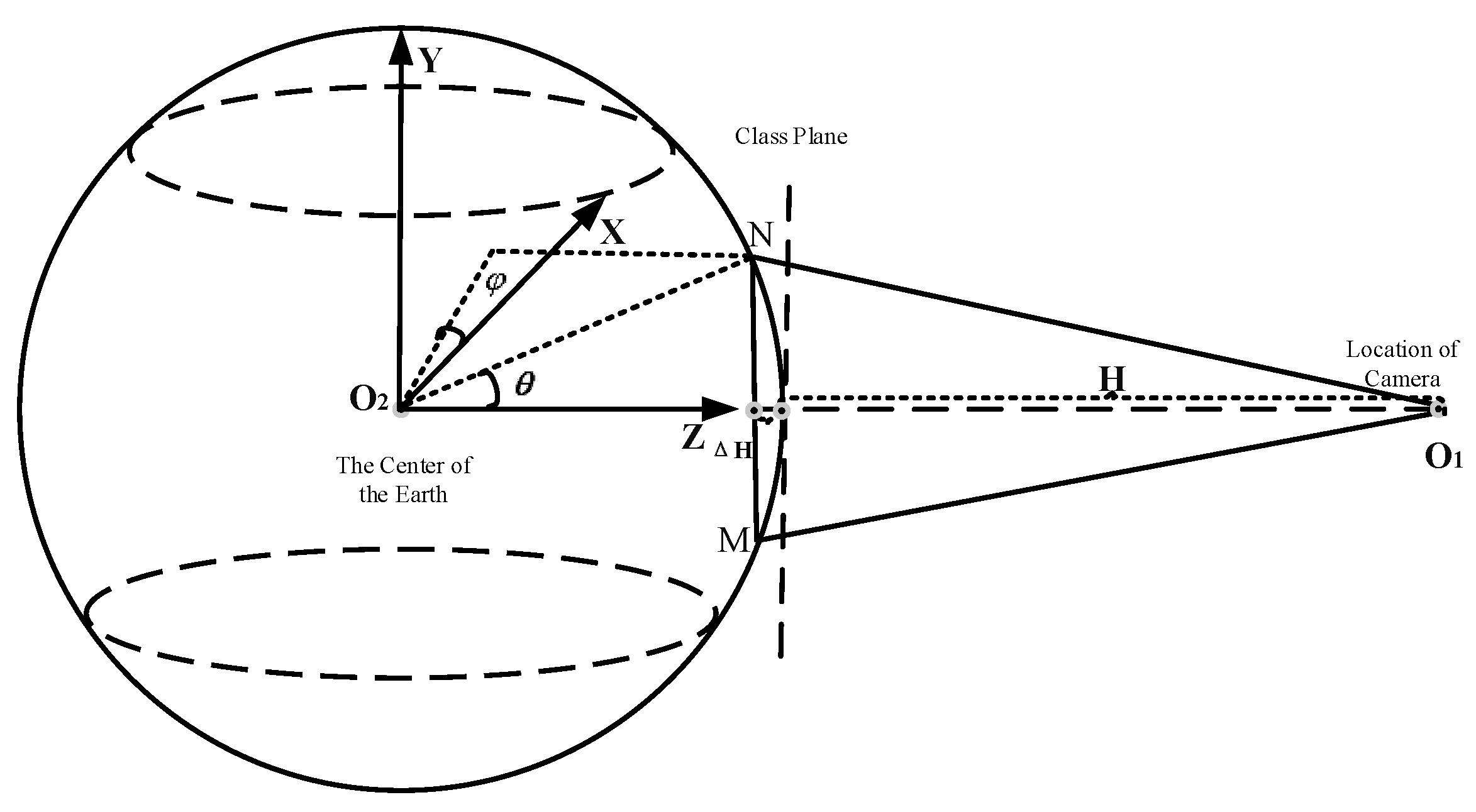
Image matching of aircraft always uses monocular vision, which can be hard to acquire profound information, consequently, during the normal processing, pictures collected always are recognized as planes and the absolute coordinates acquired always are the points within the plane. Additionally, errors may occur if this paper take the real-time pictures as a plane to solve the positioning posture. ∆H is the error, shown in the following
Figure 1.
As is shown in
Figure 1, during image matching, errors will occur because approximating the sphere as surface, which can lower the precision of positioning posture solving. Therefore, it is necessary to figure out the threshold value of the central angle to estimate the ideal errors of a plane to replace the sphere surface and the transmission law. To conquer this problem, this paper have put forward an approach for spherical EPnP positioning posture solving by measuring the central angle threshold value for scene matching of aircraft. Based on the above approach, this paper can construct theoretical models for the flying height and camera field angles. In this essay, it is named EarM_EPnP method, and the innovations for the EarM_EPnP method mainly are as follows:
This paper have put forward aircraft’s positioning posture solving with analogous three-dimensional data as input, which can effectively improve the positioning precision of flat coordinates solving with the EPnP algorithm.
It makes sure the critical value of central angle for plane replaced three-dimensional solving of scene matching on earth and it provides theoretical support for further study of positioning posture solving of scene matching.
This paper can acquire the parameters of the camera, critical angle, and the inherent relationship among field angles thus getting the corresponding function and providing measuring principles for following relevant research.
This essay mainly includes four parts. The first part is the introduction, which has introduced the research status quo of positioning posture solving for scene matching. The second part is the special approaches this essay has put forward. Additionally, the third part is for experiment and discussion and the last part is about the conclusion.
2. EarM_EPnP
The flow chart of EarM_EPnP is as follows.
Figure 2.
Flow chart of EarM_EPnP.
Figure 2.
Flow chart of EarM_EPnP.
The detailed steps of the above picture are described below.
Setting up the spherical coordinates system and getting the spherical coordinates.
Solving spherical coordinates based on EPnP and acquiring the results of solving positioning posture.
Integrating with the results of EPnP solving and taking GPS precision as a datum to decide the central angle of the earth.
Construction of theoretical models for the height of the Aerial photography, the central angle, and the field angle.
2.1. Construction of spherical coordinates
In this essay, this paper take the east, west, and celestial coordinates system. As it is shown in
Figure 1, data acquisition is always carried out using direct and downward vision for the monocular vision of aircraft. However, because monocular vision is incapable of acquiring profound information, the collected datum mark coordinates can approximate
. Nevertheless, the coordinates on the earth's surface should be
. The function of X, Y, and Z is like,
R is the radius of the earth. According to the expression of the spherical coordinates system, the datum mark coordinates of the earth's surface can be like
. For the convenience of calculating and expressing the relationship of erroneous angles, this paper take polar coordinates, so spherical coordinates are:
is the angle with the X axis. is the angle with the Z axis. Considering the independence between and , so this paper set them at the same angle.
2.2. EPnP positioning posture solving for spherical coordinates
In this essay, this paper take the approaches mentioned in document [
10] to solve positioning posture.
approximate positioning posture solution of plane coordinates system.
is the positioning posture solution of spherical coordinates system. EPnP positioning posture solution of the stated two coordinates is like:
respectively represents abscissa and ordinate. The n is about the natural number and is a noncoplanar coordinate point.
2.3. Threshold value of central angle
This method can acquire stimulative input through spherical models. Additionally, combining with the equation (3), this paper can have
which represents spherical input coordinates. The construction of plane coordinates only needs to change Z into R, thereby acquiring plane input coordinates
, which have something to do with the input variable angle-Angle. This paper did the stimulative experiments under ideal circumstances.
Equation (6) has described the generation of analog input point pair data by combining angle, internal reference matrix, rotation, and translation with the sphere model.
, setting the initial angle start and the variable
to realize even point selection on the spherical surface.
Equation (7) describes the internal reference matrix. In the process of calculating the point set, all the calculating steps are the same except and . What’s more, this paper just need to take spherical input as an example to explain plane replaced sphere input. The coordinates of the earth's surface points are expressed with analog input.
Equation (9) describes the preparation for generating two-dimensional image coordinates by multiplying the coordinates of the earth’s surface points and the internal reference matrix.
This paper can get two-dimensional coordinates (u, v) by formula (9)’s X-direction coordinates divide its Z-direction coordinates and Y-direction coordinates divide the Z-direction coordinates.
Equation(11) adds one dimension to the 2D point coordinates of the image, which can facilitate the subsequent EPnP solution. Additionally, this paper need to obtain the 3D coordinates of the global coordinates system. The dates observed are not within the camera the coordinates system. What’s more, this paper have to focus on the world’s system centroid, while assuming that the data is rotated to the camera coordinate system.
Equation (12) describes the stimulative input data rotated severally to the three directions of X, Y, and Z to prevent the fluctuation of results after introducing random variables. Therefore in this essay,
are set as 45 degrees.
Formula (13) describes the translation vector t.
Formula(14) describes the rotating matrix of combining formula (12) and formula (13) translation vector integrated to produce a rotating translation matrix, which is used to solve the global coordinates functioning as input.
Equation (15) describes the acquisition of barycenter. By barycenter and rotating translation matrix Rt, this paper can solve the global coordinates function as input.
Equation (17) adds one dimension to the 3D point coordinates, thereby facilitating further solving of EPnP. Taking equation (11), (17), and the internal reference matrix as input to substitute into EPnP to solve the posture information.
By solving, equation (18) gains the rotating matrix
and translation vector
and the positioning coordinates
of the camera.
After transforming the format of equation (19), a secondary projection error will occur and the equations are as follows.
Positioning errors rotate and translate based on the datum mark [0, 0, 0]. This paper can acquire different positions
,
after different rotation and translation are solved by spherical and plane analogous input.
Here, this essay makes the difference between the positions acquired by the two formulas above and then takes the absolute value to get the positioning error.
represents the positioning solving errors of plane coordinates system,
and
respectively describes the positioning solving results from the spherical and plane coordinates system. When
is 1m, 10m, or 100m, the central angle is the threshold value.
2.4. Model of aerial and field of view angle under fixed central angle
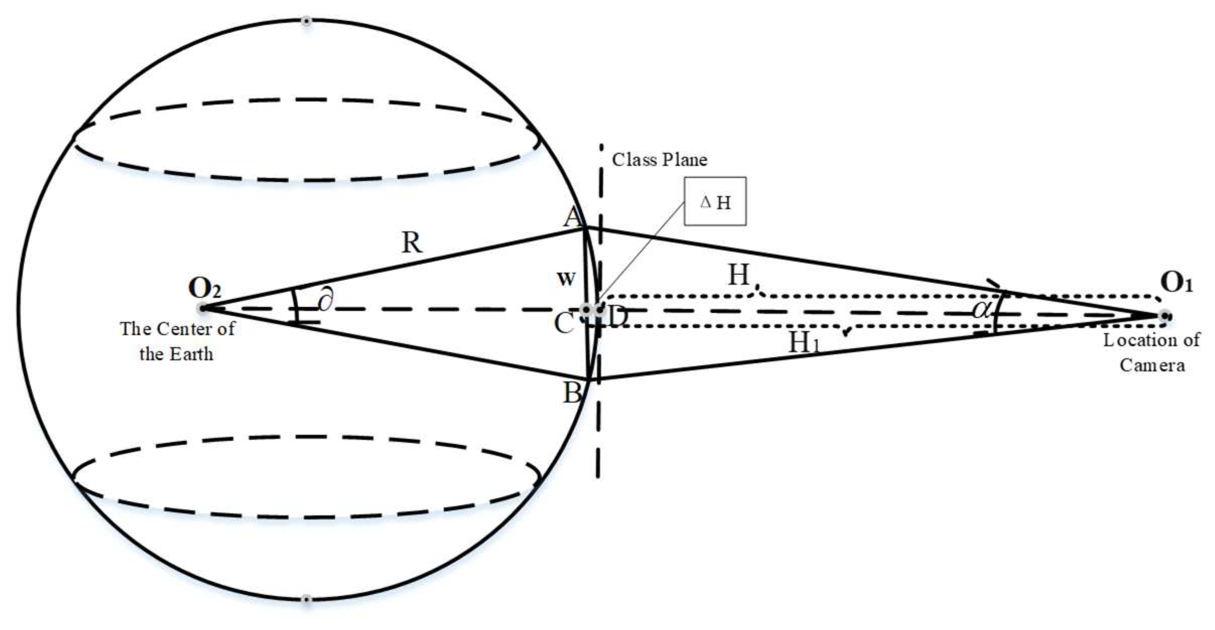
In chapter 2.3, by EPnP, this paper can solve the threshold value of central angle, thereby calculating the theoretical model for the height of aerial photography and field angle, which is shown in the following picture.
It can be seen from
Figure 3 that the relationship between the flying height and the central angle of the earth’s center is described by W, where the expression of W is as follows:
W represents the length of the line segment
, R represents the radius of the earth and
is the central angle of the earth. Additionally, the flying height of aircraft is H.
H is the flying height and
is the length of
, in other words, the height errors plus flying height.
is the length of segment
, so the height error is:
W is the length of segment
and α is the field angle of the carrying camera on aircraft.
is the length of the segment
, in other words, the flying height plus the height errors. So the function for flying height H and field angle α is as follows. Formula 10 is to describe the relationship between
and
. Equation 29 is to represent the relationship between
and
.
, , and respectively represents the flying height, field angle, and radius of the earth and is the central angle of the earth.
3. Simulative experiment and Discussion
3.1. Model of aerial and field of view angle under fixed central angle
-
1.
Experimental conditions
The experiment platform was a 64-bit Windows10 operating system based on an X64 embedded device and processor of Intel Core i7-7500U CPU, whose main frequency is 2.70GHz~2.9GHz. Based on the code in reference [
11], combined with spherical coordinates in section 2.1, this paper can construct three-dimensional spherical coordinates. The plane-like-EPnP adopts setting Z coordinates
.
-
2.
Comparison between plane coordinate results and stereo coordinate results
When the central angle is 0.6 degree, the according district on the earth's surface is
, approximately 66.723km. For aircraft flying height of 30~50km is enough. Therefore, the angle degree range is 0~0.6 degrees. To show the excellence of our approach, this paper divide the experiment into two cases. By the way, the precision formula is
is the improved positioning errors and respectively represents case2 and case1. Detailed definitions for them are as follows.
Case1 takes the coordinates of the plane coordinates system as the calculation result of EPnP algorithm data input.
Case2 takes the coordinates of the spherical coordinate system (close to an ideal state, which can be used as a reference datum)as the solution result of EPnP algorithm data input.
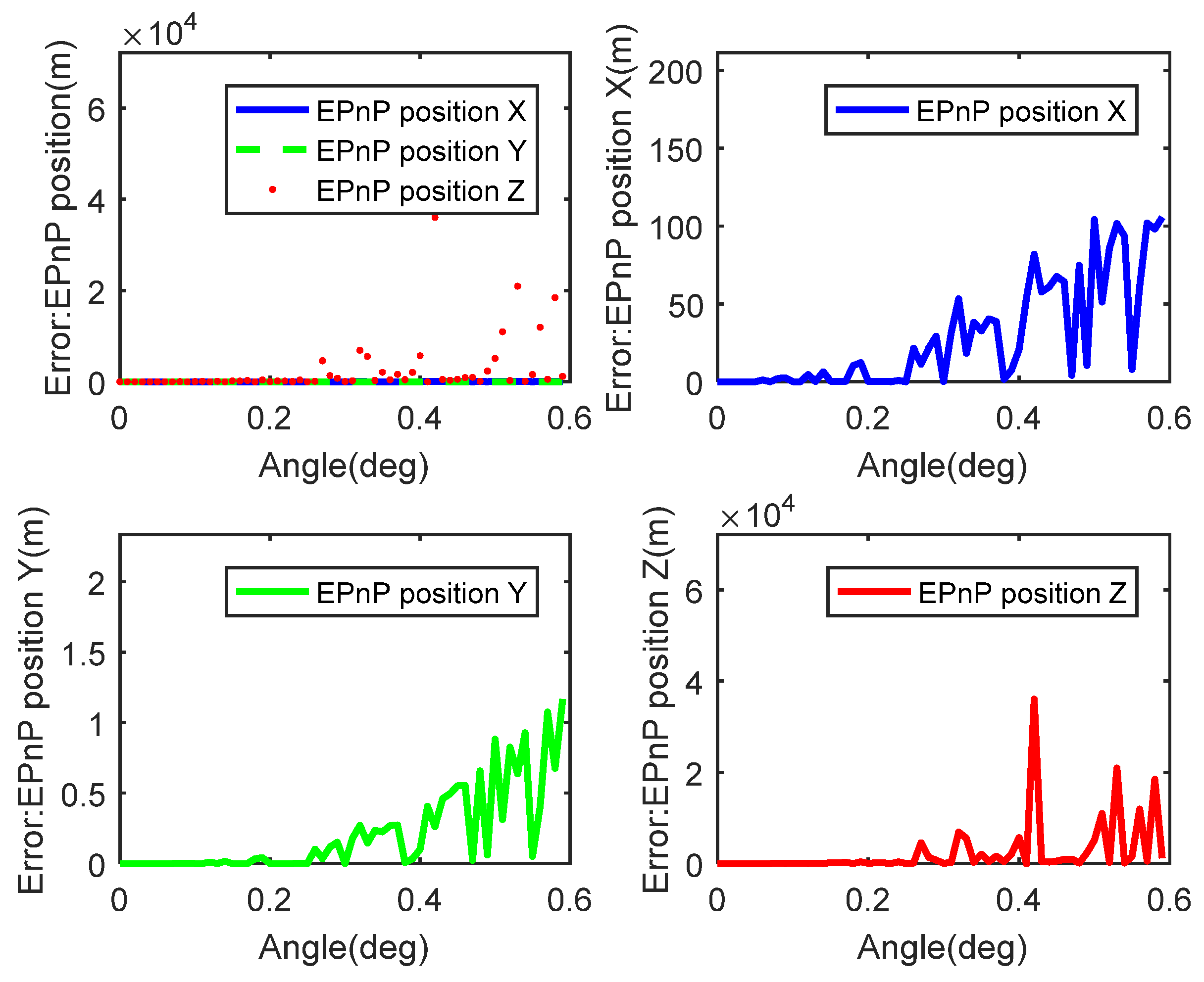
Figure 4 depicts the relationship between positioning errors and central angle solved by the EPnP algorithm with plane coordinates and spherical coordinates as inputs. By the way, the central angle also ranges from 0 to 0.6 degrees. The up-left figure is about the results of X, Y, and Z orientation. From the figure, this paper can know when the central angle is relatively small (about 0.05 degrees), plane solved results are pretty much equal to the sphere solved, and errors are about 0. However, as the central gets bigger, errors become bigger, too. If this paper analyze the X, Y, Z orientation separately, this paper will know that the errors of direction X and Y get bigger with the central angle becoming greater and fluctuation in direction Z is relatively dramatic.
Considering the number difference of central points selected during solving with EPnP algorithm, which is concluded in the below table.
Table 1 is about the relationship between positioning posture solving points and the time of the EPnP algorithm, which takes spherical coordinates as datum marks and it includes the average errors solved by different point pairs. From the table, we can know that the period for solving doesn’t strongly related and the solving time doesn’t lengthen with the increase of calculating points. What’s more, the average errors for different number of solving points aren't connected with others. Therefore, based on real stimulation, this paper take 30 as the number of solving points.
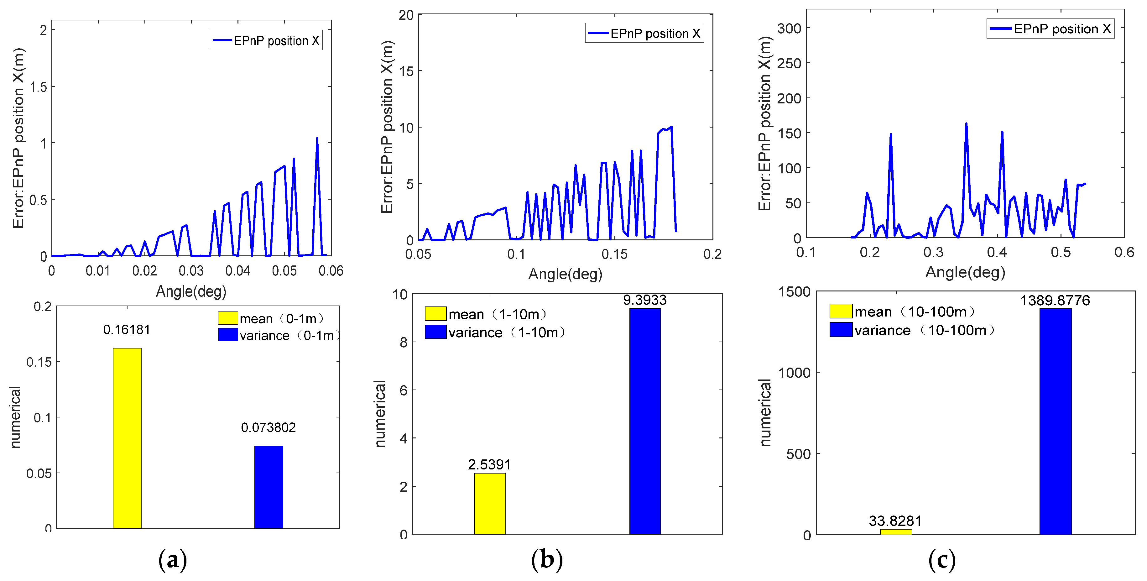
Then this paper took the precision of 1m, 10m, and 100m as an example, and this paper recorded the corresponding angles, errors, average errors, and the variance. The results are as follows.
Figure 5 is the diagram of angles, errors, average errors, and variance for the precision of 1m, 10m, and 100m. Based on
Figure 6, the positioning errors, this paper solve the positioning errors of different precision orders in a much smaller range. The up-left figure depicts the positioning accuracy of 0~1m corresponding to 0~0.6 degrees, and the width of the central angle corresponding to 1m is 0.057 degrees. The variance and the average value in the range of 0~0.059 are described in the upper right and at this time, the variance of the average value is large, which shows the system is stable and the error fluctuation is small. Additionally, the middle left figure depicts the range of 0.050~0.181 degrees corresponding to a positioning precision of 1~10m, by the way, the corresponding central angle threshold value for 10m is 0.179 degrees. The middle right figure is for the variance and average value of the range 0.050~0.05 and the variance is pretty much 3.76 times the average value. Therefore, in comparison with 0~0.06, the system becomes unstable and more fluctuant. The lower left figure is about the positioning precision of 1~10m corresponding to the angle range of 0.170~0.539. However, the fluctuation here is dramatic. According to the relationship between central and the positioning error, the corresponding central angle threshold value for the precision of 1m is 0.500 degrees. The lower right figure describes the variance and the average value of 0~0.539 degrees. At this time, the variance is about 41.12 times the average value.
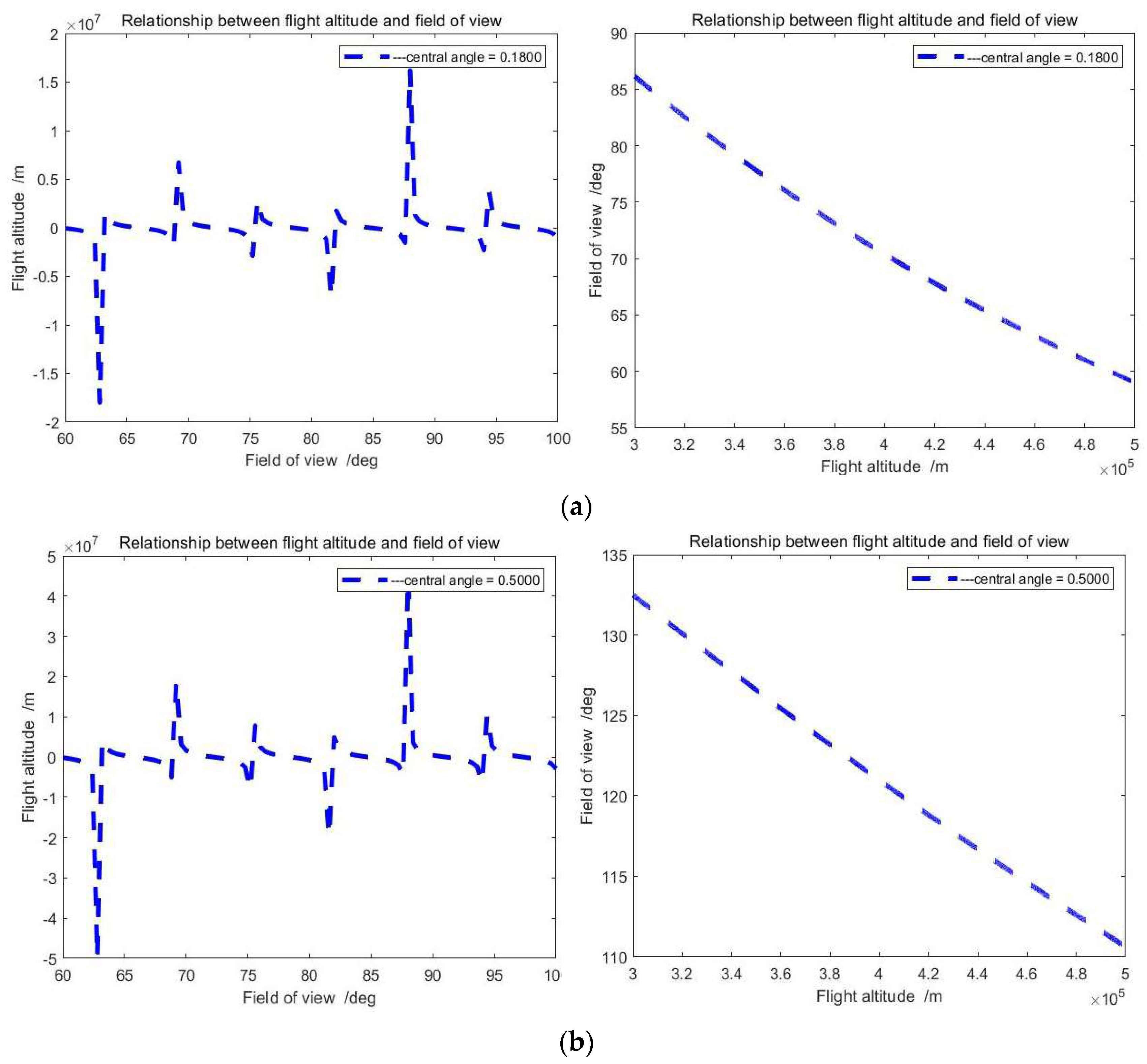
Simulative experiment results from theoretical models for field angle and flying height.
The above figures depict the relationship between flying height and field angle when the central angle is 0.1800 or 0.5000 degrees. According to the field angle, we can obtain the flying height, simultaneously, we can adjust the camera with a different field angle based on its flying height.
3.2. Discussion
In this paper, coordinate from the plane coordinate simulation to the spherical, the accuracy in the x and y directions has been improved, and there are some fluctuations in the z direction. Altitude can usually be measured with an altimeter, which can be a great addition to the entire navigation system. The experimental results also give the relationship between the flight height and the field of view of the visual sensor under a certain central angle of the earth, providing theoretical support for the autonomous flight of the subsequent aircraft.
4. Conclusion
To handle the existing problems of positioning posture solving of scene matching of aircraft, this paper introduce the three-dimensional coordinates to solve the positioning posture. The experimental results show that the three-dimensional calculation with high precision makes the whole precision increase by 16 percent, providing effective approaches for the positioning posture solving of the visual navigation. According to the relationship between flying height and field angle, this paper have accurately inferred the theoretical models in our essay and conducted analytical research. The results this paper have reached can not only provide theoretical guidance for further study of flying height and orbital improvement of the aircraft's scene matching but is also of great significance for theoretical research and application. However, of course, the theoretical analysis for the partial tendency of errors corresponding to different angle ranges will be the research focus of the next stage.
References
- XiYan, David Acuna, and SanjaFidler, “A Large-Scale Search Engine for Transfer Learning Data” 2020 IEEE/CVF Conference on Computer Vision and Pattern Recognition (CVPR), 25. pp. 2575-7075,2020.
- Simon Hadfield, Karel Lebeda, and Richard Bowden, “HARD-PnP: PnP Optimization Using a Hybrid Approximate Representation,” IEEE Transactions on Pattern Analysis and Machine Intelligence, vol. 41, no. 3, pp. 768-774, 2019. [CrossRef]
- Chi Xu, Lilian Zhang, Li Cheng, et al., “Pose Estimation from Line Correspondences: A Complete Analysis and a Series of Solutions,” IEEE Transactions on Pattern Analysis and Machine Intelligence,vol. 39, no. 6, pp. 1209-1222, 2017. [CrossRef]
- Haoyin Zhou, Tao Zhang, and Jayender Jagadeesan, “Re-weighting and 1-Point RANSAC-Based PnnP Solution to Handle Outliers,” IEEE Transactions on Pattern Analysis and Machine Intelligence,vol. 41, no. 12, pp. 1209-1222, 2019. [CrossRef]
- Bo Chen, Álvaro Parra, Jiewei Cao, Nan Li, et al., “End-to-End Learnable Geometric Vision by Backpropagating PnP Optimization,” 2020 IEEE/CVF Conference on Computer Vision and Pattern Recognition (CVPR), Seattle, WA, USA, pp. 124-127, August 2020. [CrossRef]
- Jiayan Qiu, Xinchao Wang, Pascal Fua, et al., “Matching Seqlets: An Unsupervised Approach for Locality Preserving Sequence Matching,” IEEE Transactions on Pattern Analysis and Machine Intelligence,vol. 43, no. 2, pp. 745-752, 2021. [CrossRef]
- Erik Johannes Bekkers, Marco Loog, Bart M. ter Haar Romeny, et al., “Template Matching via Densities on the Roto-Translation Group,” IEEE Transactions on Pattern Analysis and Machine Intelligence,vol. 40, no. 2, pp. 452-466, 2018. [CrossRef]
- Wengang Zhou, Ming Yang, Xiaoyu Wang, et al., “Scalable Feature Matching by Dual Cascaded Scalar Quantization for Image Retrieval,” IEEE Transactions on Pattern Analysis and Machine Intelligence,vol. 38, no. 1, pp. 159-171, 2016. [CrossRef]
- Dylan Campbell, Lars Petersson, Laurent Kneip, et al., “Globally-Optimal Inlier Set Maximisation for Simultaneous Camera Pose and Feature Correspondence,” 2017 IEEE International Conference on Computer Vision (ICCV), Venice, Italy, December 2017. [CrossRef]
- Kiru Park, Timothy Patten, and Markus Vincze, “Pix2Pose: Pixel-Wise Coordinate Regression of Objects for 6D Pose Estimation,” 2019 IEEE/CVF International Conference on Computer Vision (ICCV),Seoul, Korea (South), February 2019. [CrossRef]
- Andrea Pilzer, Stéphane Lathuilière, Dan Xu, et al., “Progressive Fusion for Unsupervised Binocular Depth Estimation Using Cycled Networks,” IEEE Transactions on Pattern Analysis and Machine Intelligence, vol. 42, no. 10, pp. 2380-2395, 2020. [CrossRef]
- Zhengxia Zou, Wenyuan Li, Tianyang Shi, et al., “Generative Adversarial Training for Weakly Supervised Cloud Matting,”2019 IEEE/CVF International Conference on Computer Vision (ICCV),Seoul, Korea (South), February 2019. 20 February 2019. [CrossRef]
- Ming Cai, Ian Reid, “Reconstruct Locally, Localize Globally: A Model Free Method for Object Pose Estimation,” 2020 IEEE/CVF Conference on Computer Vision and Pattern Recognition (CVPR), Seattle, WA, USA, August 2020.
- Hansheng Chen, Yuyao Huang, Wei Tian, et al., “Monorun: Monocular 3D Object Detection by Reconstruction and Uncertainty Propagation,” 2021 IEEE/CVF Conference on Computer Vision and Pattern Recognition (CVPR),Nashville, TN, USA, November 2021. [CrossRef]
- Kunpeng Li, Yulun Zhang, Kai Li,c “Visual Semantic Reasoning for Image-Text Matching,” 2019 IEEE/CVF International Conference on Computer Vision (ICCV), Seoul, Korea (South), February 2019.
- Haoyin Zhou, Tao Zhang, and Jayender Jagadeesan, “Re-weighting and 1-Point RANSAC-Based PnnP Solution to Handle Outliers,”IEEE Transactions on Pattern Analysis and Machine Intelligence,vol. 41, no. 12, pp. 3022-3033, 2019.
- Chunyu Wang, Yizhou Wang, Zhouchen Lin, et al., “Robust 3D Human Pose Estimation from Single Images or Video Sequences,”IEEE Transactions on Pattern Analysis and Machine Intelligence,vol. 41, no. 5, pp. 1227-1241, 2019. [CrossRef]
- Yeongmin Lee, Chong-Min Kyung, “A Memory- and Accuracy-Aware Gaussian Parameter-Based Stereo Matching Using Confidence Measure,” IEEE Transactions on Pattern Analysis and Machine Intelligence,vol. 43, no. 6, pp. 1845-1858, 2021. [CrossRef]
- Chi Xu, Lilian Zhang, Li Cheng, et al., “Pose Estimation from Line Correspondences: A Complete Analysis and a Series of Solutions,”IEEE Transactions on Pattern Analysis and Machine Intelligence,vol. 39, no. 6, pp. 1209-1222, 2017. [CrossRef]
- Huang-Chia Shih,Kuan-Chun Yu, “A New Model-Based Rotation and Scaling-Invariant Projection Algorithm for Industrial Automation Application,” IEEE Transactions on Industrial Electronics,vol. 63, no. 7, pp. 4452-4460, 2016. [CrossRef]
- Xiangzeng Liu, Yunfeng Ai, Bin Tian, et al., “Robust and Fast Registration of Infrared and Visible Images for Electro-Optical Pod,”IEEE Transactions on Industrial Electronics,vol. 66, no. 2, pp. 1335-1344, 2019. [CrossRef]
- Bo Wang, Jingwei Zhu, Zhihong Deng, and Mengyin Fu,“A Characteristic Parameter Matching Algorithm for Gravity-Aided Navigation of Underwater Vehicles,” IEEE Transactions on Industrial Electronics,vol. 66, no. 2, pp. 1203-1212, 2019.
- Shengkai Zhang, Wei Wang, and Tao Jiang,“Wi-Fi-Inertial Indoor Pose Estimation for Microaerial Vehicles,” IEEE Transactions on Industrial Electronics,vol. 68, no. 5, pp. 4331-4340, 2021.
- Zaixing He, Zhiwei Jiang, Xinyue Zhao, et al., “Sparse Template-Based 6-D Pose Estimation of Metal Parts Using a Monocular Camera,”IEEE Transactions on Industrial Electronics,vol. 67, no. 1, pp. 390-401, 2020. [CrossRef]
- Yi An, Lei Wang, Rui Ma, et al., “Geometric Properties Estimation from Line Point Clouds Using Gaussian-Weighted Discrete Derivatives,” IEEE Transactions on Industrial Electronics,vol. 68, no. 1, pp. 703-714, 2021. [CrossRef]
- Jun Yu, Chaoqun Hong, Yong Rui, et al., “Multitask Autoencoder Model for Recovering Human Poses,” IEEE Transactions on Industrial Electronics,vol. 65, no. 6, pp. 5060-5068, 2018. [CrossRef]
- Jingyu Zhang, Zhen Liu, Yang Gao, et al., “Robust Method for Measuring the Position and Orientation of Drogue Based on Stereo Vision.” IEEE Transactions on Industrial Electronics, vol. 68, no. 5, pp. 4298-4308, 2021. [CrossRef]
- Tae-jae Lee, Chul-hong Kim, and Dong-il Dan Cho, “A Monocular Vision Sensor-Based Efficient SLAM Method for Indoor Service Robots,” IEEE Transactions on Industrial Electronics,vol. 66, no. 1, pp. 318-328, 2019. [CrossRef]
- Yingxiang Sun, Jiajia Chen, Chau Yuen, et al., “Indoor Sound Source Localization With Probabilistic Neural Network,” IEEE Transactions on Industrial Electronics,vol. 65, no. 1, pp. 6403-6413, 2018. [CrossRef]
- Jundong Wu, Jinhua She, Yawu Wang, et al., “Position and Posture Control of Planar Four-Link Underactuated Manipulator Based on Neural Network Model,”IEEE Transactions on Industrial Electronics,vol. 67, no. 6, pp. 4721-4728, 2020. [CrossRef]
|
Disclaimer/Publisher’s Note: The statements, opinions and data contained in all publications are solely those of the individual author(s) and contributor(s) and not of MDPI and/or the editor(s). MDPI and/or the editor(s) disclaim responsibility for any injury to people or property resulting from any ideas, methods, instructions or products referred to in the content. |
© 2023 by the authors. Licensee MDPI, Basel, Switzerland. This article is an open access article distributed under the terms and conditions of the Creative Commons Attribution (CC BY) license (https://creativecommons.org/licenses/by/4.0/).

