
Submitted:
28 June 2023
Posted:
29 June 2023
You are already at the latest version
Abstract
Off-road vehicles and transportation are vital for agricultural economics, yet the transition to green energies is challenging. To make this application easier, a tool that enables the testing of heavy-duty off-road vehicles in various scenarios was created. Based on the methods of the World Harmonized Transient Cycle, a new Hybrid Operational Cycle that reflects the features of agricultural work was created and applied in a graphical model simulation. This was a newly developed methodology. The cycle and the model were based on gathered research data. A numerical model of a medium-power tractor with an internal combustion engine and a series-hybrid setup was created, and simulations were performed in Matlab and AVL Cruise. The research compared both diesel and hybrid vehicles in terms of their power production, fuel consumption, and efficiency in fieldwork and transportation scenarios. The research showed that a series-hybrid transmission can achieve an efficiency similar to that of tractors with a continuously variable transmission (CVT), but with the use of an electric powertrain, there is still an opportunity to exploit energy regeneration in transportation and under low-load conditions. The designed model also may be used for the development of control algorithms for hybrid drives and the improvement of the efficiency thereof.
Keywords:
series hybrid
; off-road
; heavy duty
; WHTC
; hybrid
; tractor
; hybrid drive cycle.
1. Introduction
The Green Course and emission requirements for vehicles are becoming tighter and tighter, and this is not only limited to road vehicles. In recent years, this direction of more sustainable living has caused a greater interest in agricultural vehicles as a research field for transport development [1,2,3]. To make tractors work more efficiently, electrification is recognized as the most promising means, as electric motors—especially those for propulsion systems—have grown in power and become smaller in size since they were first developed [4,5,6,7,8].
Few types of applications of electrification are being tested. In the early development of heavy-duty vehicles, series-hybrid systems were used to match the high power demand. Kim et al. [9,10] proposed a series-hybrid electric vehicle with an engine and alternator couple, four inverters, and a battery, as well as an energy management strategy that allowed the use of the vehicle in three modes: with an internal combustion engine (ICE) as a primary energy source, as an electric vehicle that was powered by the battery, and as a hybrid that could be powered both by the ICE and additionally stored energy. This application showed a promising amount of fuel savings, but despite its high power, the vehicle was of a medium weight, and it was tested under road conditions, not on rough terrain. A quite different approach was taken by Feng [11,12], who developed a hybrid electric mining truck. Special work conditions—even when comparing agricultural vehicles—require special energy management strategies. However, this research, as well as others that have considered heavy-duty transport, is a good indication that a series-hybrid system is suitable for off-road vehicles [13,14,15,16,17].
There are two main criteria for efficient hybrid vehicles. The energy management strategy (EMS) is a focal point for this, especially when moving from general road cars to special forms of transport [18,19,20,21]. The more complex the vehicle setup is, the more complex the control of efficient energy usage will be [22,23,24,25]. Xu et al. named the large load fluctuations that occur in fieldwork with an agricultural vehicle as an important source for the selection of an effective EMS [26]. Another focal point is an efficient transmission. To achieve this, several methods have been established. Dou et al. suggested an application in which an EMS was used to partly replace a complicated generally used transmission [27]. Dual-powered hybrid vehicles have also been widely proposed, but the approaches differ. Zhu et al. [28] applied a dual power source by using a parallel-hybrid system and an EMS with five modes. The performance of the vehicle was assured by the same hydromechanical continuously variable transmission (CVT). Goswami et al. [29] compared a series-hybrid system and a series–parallel-hybrid system and kept the initial transmissions of the vehicles. However, neither of these studies provided comparable data for evaluating the overall efficiency of hybrid tractors in comparison with conventional ones.
Another method of dual power is provided by Mocera [30,31,32,33]. In this research, an ICE and a motor couple were used, as well as an additional motor, which enabled the use of a hybrid e-CVT. This hybrid performed well with a high power demand and featured an overall decrease in fuel consumption in comparison with conventional vehicles. Dual-power applications are also seen in fully electrical heavy-duty vehicles, but these models can be used more successfully in on-road transportation [34,35,36,37].
As different studies have described, the use of a power split allows one to downsize an ICE unit and increase the fuel efficiency for that reason alone. Additionally, by altering the transmission of an off-road heavy-duty vehicle, the efficiency can be increased. It is hypothesized that a CVT can be replaced by highly effective electric motors [17,38,39,40,41,42,43], thus achieving similar transmission effectiveness yet reducing the number of parts that cause mechanical losses. In this study, a method of power splitting for a series-hybrid system is studied.
There is still not a single methodology for assessing the efficiency of hybrid heavy-duty vehicles. In this study, based on research and scientific sources, a heavy-duty vehicle performance evaluation cycle consisting of speed–time and variable-load functions was developed. By using this cycle, the efficiency of conventional and hybrid tractors was investigated and compared.
2. Methods
2.1. Vehicle models
An off-road heavy-duty vehicle is a machine that weights more than 10 tons and is used for high-tow-demand and high-torque tasks, such as agricultural work, forestry, and transportation of harvested raw materials. To compare the execution of these tasks between a vehicle that has a series-hybrid drive installed (Figure 1a) and a common CVT version of that vehicle (Figure 1b), a simplified graphical model was created for both vehicle options. Both vehicles featured the same 254 kW diesel engine to generally power the 14-ton vehicle. The final drive ratio for both vehicles was 28. The hybrid vehicle was equipped with an ICE-matching alternator, two 100 kW electric motors (one for each driving axle), and a 46 Ah battery to store excess energy. The CVT used for the non-hybrid vehicle was the ZF ECCOM 3.5.
The start and the end of these schemes were similar, but the hybrid had more components that could cause higher transmission losses. On the other hand, the CVT vehicle might appear simple, but the main transmission (CVT) part was quite complex and could also cause considerable losses, as well as high efficiency.
There was also a difference in how the power demand was distributed in these two models. Despite the length of the drivetrain of the hybrid vehicle, the required power for overcoming the resistance force was supplied at the end of the chain. The path of in the CVT vehicle was slightly longer, which could cause higher energy losses and, thus, consume more power for overcoming the resistance than in the hybrid vehicle.
Another difference between the hybrid and CVT vehicles was point in the drivetrain chain at which the optimal torque could be applied. The optimal torque is a load point at which the highest efficiency available is reached. In the hybrid vehicle, was reached by using an ICE, allowing its fuel consumption to be cut The CVT vehicle was more concentrated on having different speed-to-torque ratios than on achieving lower fuel consumption related to power output, whereas could be a sign of a higher transmission efficiency, but not in direct relation to the ICE. To determine which drivetrain was more efficient overall, this method of evaluation was established.
To apply the use of the optimal torque in the ICE of the hybrid vehicle, a control algorithm (Figure 2) was used. It can be divided into the main parts: a loop for the ICE mode, another one for charging/discharging, and a third one for regeneration.
An ICE has two main operational modes: the Power mode, which is used when the required power for electric motors exceeds the power generated by the supply couple of an ICE and an alternator, and the Torque mode, which is used when the power generated is greater than the power demand, and the excess energy can be stored. In this mode, is reached.
The hybrid powertrain was managed according to the efficiency of the internal combustion engine to keep it at its optimal point.
The supply couple was controlled by a state of charge (SOC) of a battery. After reaching 100% charge, the switch of the ICE was turned off and was turned back on then the SOC dropped below 30%.
Electric motors, as well as ICEs, have two modes: the Motor mode and the Alternator mode. Normally, the motor works as a drive until the braking phase, when it starts collecting brake energy. The charging mode can be used both with a working main alternator or separately as a means of extending the vehicle’s working on fully electric energy.
A numerical model of a hybrid and a conventional tractor was built by using the AVL Cruise 2016 software package, and MATLAB 2021b was used for the management algorithms (Figure 3).
The tractor dynamic was described using a longitudinal dynamic model shown in Figure 3a and given by the following equations:
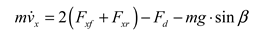
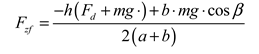
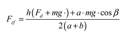
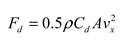 where and —the relative position of the center of gravity of the vehicle with respect to the front and rear axles; —the tractor mass; —the acceleration of gravity; —the road slope angle; —the vehicle longitudinal speed; —the aerodynamic drag force; —the air density; —the drag coefficient; —the frontal cross sectional area of the vehicle; and — the contact forces between the wheels and the ground on the longitudinal direction (front and rear axle); and —the normal contact forces between the wheels and the ground (front and rear axle).
A representative numerical model of an agricultural tractor must be able to describe subsystems from several physical domains. As shown in Figure 3b, Physical Network (PN) modeling approach was chosen to model the architecture of both the traditional and hybrid electric power unit of the tractor considered for this study. Mechanic and electric parts of the vehicle model are connected using a CAN Bus, that includes signal control using component map as well as component behaviour programming. The PN is a modular modeling approach where each element is considered as a physical entity capable of exchanging energy with all the other subsystems to which it is connected. The solution of the systems must satisfy the power balance equations for each component at each time step.
2.2. Hybrid Operational Cycle
The WHTC was created to evaluate the emissions of heavy-duty engines, regardless of their application, but to use it correctly, this cycle requires a transmission model [44]. This makes the WHTC less likely to be used in the early stages of vehicle development, especially in small batches or unit production. The WHTC is based on engine load, and it differs for trucks that are used as a means of road transportation and for agricultural vehicles, as these have relatively defined fields of application. A cycle based on time-dependent velocity would make comparisons of agricultural vehicles easier.
A lack of standardized testing for such hybrid vehicles has been perceived [45]. Based on the WHTC, WTVC, and research on the work tendencies of heavy-duty off-road machinery, a new cycle was formed. This cycle describes the typical operations of an agricultural vehicle by using time-dependent velocity and keeping the proportions of different work types, such as fieldwork and steady-state work, as well as local and transitional transportation. By using this cycle, the efficiency of any type of drivetrain can be described and compared. Due to this property, this cycle is called the Hybrid Operational Cycle (HOC) (Figure 4), and for better accuracy in simulations, it can be proportionally extended, in which case it gains the name of the Extended Hybrid Operational Cycle.
The Hybrid Operational Cycle is composed of three parts. The first part (0–1250 s) (part 1) is the longest and shows different work cycles. It was formed by using data collected from various types of field- and forestry work with various durations and speeds at each time interval. Overall, work accounted for nearly 70% of all agricultural vehicle operations, with some machines almost never leaving the field, while others mainly performed transportation work.
This cycle has another advantage, which is its use in agricultural vehicle evaluation—based on the focus of one vehicle performing a specific task, a specific part of the cycle can be used for evaluation. Another 30% of the cycle time represents transportation. Part 2 (1250–1700 s) and part 3 (1700–2000 s) are separate to describe different types of transportation. Part 2 features a slower speed because it marks local transportation—moving from field to field, collecting raw materials, and towing loaded trailers to storage. Part 3 of the HOC represents high-speed transportation, which is used when delivering goods and participating in traffic.
Part 1 represents off-road work conditions, so it had to be designed from scratch. Parts 2 and 3 represent movement on a road, so the WHTC was adopted. The transportation parts of the cycle were generated by taking the engine load value from the WHTC and converting it into a load that matched the maximum speed of an agricultural vehicle. It was assumed that the vehicle could typically reach a maximum speed of 40 km/h, with some reaching lower and some reaching higher than that.
Another property that could be involved in this cycle was the road condition. Without evaluating changing road conditions, the results can be used to compare fewer vehicles, although overall better results might be shown. To obtain results that are as accurate as possible, road properties must be taken into account. The road properties applied in this research are presented in Table 1.
In Table 1, the rolling resistance is expressed as a coefficient. The tire friction is also expressed as a coefficient, and it has a specific value for each tire/road match. In Part 1, the working ground can differ widely; in this case, a medium resistance was chosen. This can be described as a slightly moist soil that is relatively smooth and can be easily moved on. The rolling resistance for transportation is similar, but part 2 of the cycle represents moving on a gravel road, and Part 3 involves an asphalt road. This difference can be noted due to the different friction coefficients.
3. Discussion of the Results
Both hybrid and non-hybrid vehicle work cycles are shown in this section. The use of the Extended Hybrid Operational Cycle was used to provide a vehicle performance evaluation in real-life-like conditions. It was used to determine the advantages and disadvantages of hybrid drive usage in vehicles for off-road work and in road transportation.
A hybrid drive in heavy-duty off-road vehicles enables one to adjust the required engine power according to its efficiency, as does the CVT. However, the means of doing so are quite different. The hybrid vehicle had an ICE accompanied by an alternator and a battery, which allowed the ICE to work in bursts during the cycle, and this was not necessarily based on the current power demand. The CVT could adjust to the power demand and keep the relatively optimal ICE efficiency, although it had to work continuously throughout the whole cycle. The power bursts of the hybrid drive and continuous power of the CVT vehicle are shown in Figure 5.
The ICE of the hybrid vehicle kept working at the optimal point of engine efficiency during the whole operational time, unlike that of the CVT vehicle, which produced a roughly even amount of power during the cycle, with few power outbursts at acceleration points in part 1 of the cycle. At the beginning of part 1 of the EHOC, the hybrid vehicle produced around 2.5 times the power that the CVT did. However, the greater power produced in the short term led to a production time that was 3.5 times shorter. Moreover, this highly intensive energy production had a better fuel-to-power ratio, as depicted in Figure 6.
During the investigated cycle, both vehicles indicate overall narrow specific fuel consumption distributions (Figure 6), which corresponded to their power production with bursts of higher consumption for the CVT vehicle and power breaks for the hybrid vehicle (Figure 7).
Due to the high power production of the hybrid vehicle, its fuel consumption according to mass was also significantly higher (approximately 2.2 times) than that of the vehicle using the CVT. The ICE and CVT coupling had a good adaptability for major speed changes, as it did when starting from the steady state and reaching the determined vehicle velocity. However, it did not adapt as well to lower speeds in relation to time changes. This property determined the overall higher fuel consumption for the CVT vehicle (Figure 8).
Despite the fact that the hybrid vehicle used significantly more fuel in its generation mode, the efficiency of the working point of its ICE resulted in overall better fuel consumption than that obtained when using the CVT vehicle in the same operational cycle. In part 1 of the EHOC, there was also less power generated by the hybrid vehicle for the same work conditions, and there was an outcome of a higher overall vehicle efficiency compared to that of the CVT. The hybrid vehicle produced around 30% less power for the same task while using around 40% less fuel, which is a relevant indication in part 1 describing fieldwork, as no hybrid regeneration was available (Figure 9).
In part 2 of the EHOC, which represented local transportation, there were no such differences in power generation between the hybrid vehicle and the CVT vehicle (Figure 8). Nevertheless, the hybrid vehicle used less fuel; in this case, there were some contributions of its regeneration ability. Another point that is essential to note is that in part 3, which described transportation in traffic, the hybrid vehicle used the same energy as that generated in part 2, thus significantly reducing the overall demand for power production.
Not all of the power generated by the ICE in the hybrid vehicle was used to complete the cycle; even the amount of generated power was slightly smaller than that for the CVT vehicle (Figure 8). A part of that generated power was stored in a battery and used after it was fully charged. The use of the battery formed two generation phases—one in the beginning of the cycle, which was prolonged due to the high power consumption for performing the task, and another one that took place at the end of part 1 and extended to part 2 of the EHOC. The second charging phase was shorter than the first one, since the vehicle had lower demand conditions in part 2 of the cycle. As a result, the use of the hybrid drive enabled the vehicle to finish the cycle while still having energy reserves.
Figure 9 shows the power regeneration of the hybrid vehicle. In part 1 of the cycle, the regeneration was minor. In part 2 and part 3, regeneration came into the picture. The transportation velocities differed by about 10 km/h between local transportation and transportation while participating in traffic, yet in the latter, the amount of regenerated power was significantly noticeable (Figure 10).
In part 2 of the cycle, only around 9% of the charged kilowatt-hours were gained from regeneration; the vast majority of power was still stored from surplus of the power produced by the ICE and alternator. However, since the battery was fully charged in the beginning of part 2 of the cycle, there was no further usage of the ICE in part 3. Therefore, all energy that was charged was acquired from the regeneration of the electric motors. The difference between the energy recovered in part 2 and part 3 was determined not only by the velocity differences during transportation, but also by the road characteristics, which allowed for the vehicle to move more easily in part 3, giving much more inertia to this heavy machinery.
The most efficient charging occurred in part 2 of the EHOC. This happened according to the amount of charge being gained in a relatively short time. In comparison, long charging periods took place in part 1 (Figure 9), but these periods were prolonged because the majority of the power generated in this part was consumed to perform the cycle task (Figure 11). It is necessary to point out that the amount of discharged energy shown in Figure 6 is not the same as that in Figure 11. In Figure 10, the discharge refers to energy that was initially stored in the battery and later used when the ICE of the hybrid vehicle was not operating. In Figure 11, the overall energy consumed by the electric motors is noted, regardless of its origin.
The power consumed by the vehicles was not proportional to the generated power. As shown in Figure 8, in all parts of the cycle, the CVT vehicle had higher power production than that of the hybrid vehicle, regardless of the different amounts. The hybrid vehicle generated less power but consumes more. However, it did that while maintaining lower fuel consumption (Figure 11). It can be stated that the hybrid vehicle had more losses when using only electric motors as a transmission compared to the vehicle using the CVT, which had a better transmission efficiency, but its ICE worked less efficiently. In general, using less initial power led to an overall higher vehicle efficiency, and, at the end of the cycle, the hybrid vehicle had the advantage of stored excess power (Figure 9, Figure 10). At the end of the EHOC, the hybrid had a battery charge of around 80%, which could be used to start another full EHOC.
Figure 12 shows the power consumed during each part of the extended cycle and the amount of battery charge required to cover that power demand. As in Figure 9, Figure 12 illustrates that in part 1 of the EHOC, the battery was incapable of supplying enough energy for the entire work duration. It surpassed 100% of its capacity, even when taking the 30% reserve power into account. However, in parts 2 and 3, it took only a fraction of the battery capacity to run for the entire durations if it started with a full charge.
4. Conclusions
Authors should discuss the results and how they can be interpreted from the perspective of previous studies and of the working hypotheses. The findings and their implications should be discussed in the broadest context possible. Future research directions may also be highlighted.
Introducing the Hybrid Operational Cycle enabled a comparison of the benefits of a hybrid vehicle with those of a conventional one. The results showed that having a steady work point for an ICE in a hybrid vehicle requires overall up to 45% less power to complete the same task as with a conventional CVT vehicle, which can also work in relatively steady cycles, but does not have the ability to store and use surplus energy. Using the stored energy and enabling the ICE of a hybrid to work in intervals saves up to 55% of the fuel for the tested cycle conditions.
The direct power-to-fuel efficiency ratio of the hybrid drive was 18% higher than that for the CVT vehicle. Despite that, at the end of the cycle, the battery charge of the hybrid was 80%, which could provide an additional power of 23 kWh, thus raising the fuel efficiency to near 32% for these cycle conditions. However, changing the workload and facing more demanding soil conditions might adjust the overall efficiency of hybrid heavy-duty off-road vehicles by forcing the ICE to provide more power and feature inferior fuel consumption rates if the battery charge is sufficient to meet the power demand. However, as previous research by the authors showed, a hybrid drive can be both less and more efficient on rough terrain, and with an initial plug-in charge of 100% and a power split in use, possible drops in the efficiency of the ICE can be avoided. Additionally, the use of a hybrid drive would still be the best option for transportation.
The results of this research are yet to be confirmed by experimental data; additional tests of the series-hybrid efficiency under rougher work conditions and with a significant workload are planned. To date, there have been several confirmations of the beneficial use of power-split hybrid drives in agricultural and forestry vehicles. The hybrid drive concept proposed in this study can be easily applied to modify vehicles that are currently in use. With this approach to creating a reasonable evaluation method for high-demand hybrid vehicles, this work confirms the possibility of achieving greener agriculture by using electrification.
Author Contributions
Conceptualization, U.K.M, R.M., VL. and S.K.; methodology, U.K.M, R.M., VL. and S.K.; software, U.K.M, R.M., VL. and S.K.; validation, U.K.M, R.M., VL. and S.K.; formal analysis, U.K.M, R.M., VL. and S.K.; investigation, U.K.M, R.M., VL. and S.K.; resources, U.K.M, R.M., VL. and S.K.; writing—original draft preparation, U.K.M, R.M., VL. and S.K.; writing—review and editing, U.K.M, R.M., VL. and S.K.; visualization, U.K.M, R.M., VL. and S.K. All authors have read and agreed to the published version of the manuscript.
Funding
This research received no external funding.
Institutional Review Board Statement
Not applicable.
Informed Consent Statement
Not applicable.
Data Availability Statement
Not applicable.
Conflicts of Interest
The authors declare no conflict of interest.
References
- Sato, S.; Jiang, Y.J.; Russell, R.L.; Miller, J.W.; Karavalakis, G.; Durbin, T.D.; Johnson, K.C. Experimental driving performance evaluation of battery-powered medium and heavy duty all-electric vehicles. International Journal of Electrical Power & Energy Systems 2022, 141, 108100. [Google Scholar] [CrossRef]
- Troncon, D.; Alberti, L. Case of Study of the Electrification of a Tractor: Electric Motor Performance Requirements and Design. Energies 2020, 13. [Google Scholar] [CrossRef]
- Ghobadpour, A.; Monsalve, G.; Cardenas, A.; Mousazadeh, H. Off-Road Electric Vehicles and Autonomous Robots in Agricultural Sector: Trends, Challenges, and Opportunities. Vehicles 2022, 4, 843–864. [Google Scholar] [CrossRef]
- Li, T.; Xie, B.; Li, Z.; Li, J. Design and optimization of a dual-input coupling powertrain system: A case study for electric tractors. Applied Sciences 2020, 10, 1608. [Google Scholar] [CrossRef]
- Lee, D.; Kim, Y.; Choi, C.; Chung, S.; Inoue, E.; Okayasu, T. Development of a Parallel Hybrid System for Agricultural Tractors. Bulletin of Faculty of Agriculture, Kyushu University 2017, 62, 137–144. [Google Scholar] [CrossRef]
- Moreda, G.P.; Munoz-Garcia, M.A.; Barreiro, P. High voltage electrification and agricultural machinery—A review. Energy Conversion and Management 2016, 115, 117–131. [Google Scholar] [CrossRef]
- Un-Noor, F.; Wu, G.; Perugu, H.; Collier, S.; Yoon, S.; Barth, M.; Boriboonsomsin, K. Off-Road Construction and Agricultural Equipment Electrification: Review, Challenges, and Opportunities. Vehicles 2022, 4, 780–807. [Google Scholar] [CrossRef]
- Mocera, F.; Martelli, S.; Somà, A. . State of the Art and Future Trends of Electrification in Agricultural Tractors. SAE Technical Paper 2022. [Google Scholar] [CrossRef]
- Kim, D.-M.; Benoliel, P.; Kim, D.-K.; Lee, T.H.; Park, J.W.; Hong, J.–P. Framework development of series hybrid powertrain design for heavy-duty vehicle considering driving conditions. In IEEE Transactions on Vehicular Technology, vol. 68, no. 7, pp. 6468–6480, July 2019. 20 July. [CrossRef]
- Kim, D. –M.; Lee, S. –G.; Kim, D.-K.; Park, M.-R.; Lim, M.-S. Sizing and optimization process of hybrid electric propulsion system for heavy-duty vehicle based on Gaussian process modeling considering traction motor characteristics. Renewable and Sustainable Energy Reviews 2022, 161, 11228. [Google Scholar] [CrossRef]
- Feng, Y. , Dong, Z. Optimal energy management with balanced fuel economy and battery life for large hybrid electric mining truck. Journal of Power Sources 2020, 454, 227948. [Google Scholar] [CrossRef]
- Feng, Y.; Dong, Z. Comparative lifecycle costs and emissions of electrified powertrains for light-duty logistics trucks. Transportation Research Part D: Transport and Environment 2023, 117, 103672. [Google Scholar] [CrossRef]
- Lajunen, A. , & Suomela, J. Evaluation of energy storage system requirements for hybrid mining loaders. IEEE transactions on vehicular technology 2012, 61.8: 3387-3393. [CrossRef]
- Yang, W. , Liang, J., Yang, J., Zhang, N. Investigation of a novel coaxial power-split hybrid powertrain for mining trucks. Energies 2018, 11, 172. [Google Scholar] [CrossRef]
- Ceraolo, M.; Lutzemberger, G. Heavy-duty hybrid transportation systems: Design, modeling, and energy management. In Hybrid Energy Systems, Hybrid Technologies for Power Generation, Lo Faro, M., L., Barbera, O., Giacoppo, G. Eds: Academic Press, 2022, 313-336. [CrossRef]
- Medževeprytė, U.K.; Makaras, R.; Lukoševičius, V.; Keršys, A. Evaluation of the Working Parameters of a Series-Hybrid Tractor under the Soil Work Conditions. Tehnički vjesnik 2022, 29, 45–50. [Google Scholar] [CrossRef]
- Medževeprytė, U.K.; Makaras, R.; Rimkus, A. Efficiency of an off-road heavy-duty series hybrid drive based on a modified world harmonized transient cycle. Transport problems 2022, 17, 187–195. [Google Scholar] [CrossRef]
- Xie, S.; Peng, J.; He, H. Plug-in hybrid electric bus energy management based on stochastic model predictive control. Energy Procedia 2017, 105, 2672–2677. [Google Scholar] [CrossRef]
- Wu, Z.; Xie, B.; Li, Z.; Chi, R.; Ren, Z.; Du, Y.; Hirai, Y. Modelling and verification of driving torque management for electric tractor: Dual-mode driving intention interpretation with torque demand restriction. Biosystems Engineering 2019, 182, 65–83. [Google Scholar] [CrossRef]
- Yang, H.; Sun, Y.; Xia, C.; Zhang, H. Research on Energy Management Strategy of Fuel Cell Electric Tractor Based on Multi-Algorithm Fusion and Optimization. Energies 2022, 15, 6389. [Google Scholar] [CrossRef]
- Wang, S.; Wu, X.; Zhao, X.; Wang, S.; Xie, B.; Song, Z.; Wang, D. Co-optimization energy management strategy for a novel dual-motor drive system of electric tractor considering efficiency and stability, Energy 2023, 128074. [CrossRef]
- Rossi, C. , Pontara, D., Falcomer, C., Bertoldi, M., Mandrioli, R. A hybrid–electric driveline for agricultural tractors based on an e-CVT power-split transmission. Energies 2021, 14, 6912. [Google Scholar] [CrossRef]
- Gupta, S.; Maity Sr, R.; Kulkarni Ceng, S. Modeling, Analysis and Experimental Validation of Tractor Architectures for Rural Electrification. In Proceedings of the 8th SAEINDIA International Mobility Conference & Exposition and Commercial Vehicle Engineering Congress 2013 (SIMCOMVEC), Chennai, India, 4–7 December 2013. [Google Scholar]
- Scolaro, E.; Alberti, L.; Barater, D. Electric Drives for Hybrid Electric Agricultural Tractors. In Proceedings of the 2021 IEEE Workshop on Electrical Machines Design, Control and Diagnosis (WEMDCD), Modena, Italy, 8–9 April 2021; pp. 331–336. [Google Scholar] [CrossRef]
- Bouquain, D.; Blunier, B.; Miraoui, A. HEV series architectures evaluation: Modeling, simulation and experimentation. In Proceedings of the 2009 IEEE Vehicle Power and Propulsion Conference, Dearborn, MI, USA, 7–10 September 2009; pp. 584–591. [Google Scholar] [CrossRef]
- Xu, W.; Liu, M.; Xu, L.; Zhang, S. Energy Management Strategy of Hydrogen Fuel Cell/Battery/Ultracapacitor Hybrid Tractor Based on Efficiency Optimization. Applied Sciences 2023, 13, 151. [Google Scholar] [CrossRef]
- Dou, H.; Wei, H.; Zhang, Y.; Ai, Q. Configuration Design and Optimal Energy Management for Coupled-Split Powertrain Tractor. Machines 2022, 10, 1175. [Google Scholar] [CrossRef]
- Zhu, Z. , Zeng, L., Chen, L., Zou, R., Cai, Y. Fuzzy Adaptive Energy Management Strategy for a Hybrid Agricultural Tractor Equipped with HMCVT. Agriculture 2022, 12, 1986. [Google Scholar] [CrossRef]
- Goswami, G.; Tupitsina, A.; Jaiswal, S.; Nutakor, C.; Lindh, T.; Sopanen, J. Comparison of various hybrid electric powertrains for non-road mobile machinery using real-time multibody simulation. In IEEE Access 2022, 10, 107631–107648. [Google Scholar] [CrossRef]
- Mocera, F. , Martini, V., Somà, A. Comparative Analysis of Hybrid Electric Architectures for Specialized Agricultural Tractors. Energies 2022, 15, 1944. [Google Scholar] [CrossRef]
- Mocera, F. , & Martini, V. Numerical performance investigation of a hybrid eCVT specialized agricultural tractor. Applied Sciences 2022, 12, 2438. [Google Scholar] [CrossRef]
- Mocera, F.; Somà, A. A. A Review of Hybrid Electric Architectures in Construction, Handling and Agriculture Machines. In New Perspectives on Electric Vehicles; IntechOpen: London, UK, 2021; Available online: https://books.google.lt/books?hl=lt&lr=&id=jtFuEAAAQBAJ&oi=fnd&pg=PA49&dq=A+Review+of+Hybrid+Electric+Architectures+in+Construction,+Handling+and+Agriculture+Machines&ots=SAjwcZEdoG&sig=-CM7MxMM5GWUCljNwY6ckThX3EY&redir_esc=y#v=onepage&q=A%20Review%20of%20Hybrid%20Electric%20Architectures%20in%20Construction%2C%20Handling%20and%20Agriculture%20Machines&f=false (accessed on 15 April 2023).
- Mocera, F. A Model-Based Design Approach for a Parallel Hybrid Electric Tractor Energy Management Strategy Using Hardware in the Loop Technique. Vehicles 2020, 3, 1–19. [Google Scholar] [CrossRef]
- Li, T. , Xie, B., Li, Z., & Li, J. Design and optimization of a dual-input coupling powertrain system: A case study for electric tractors. Applied Sciences 2020, 10, 1608. [Google Scholar] [CrossRef]
- Wang, X.; Huang, Y.; Wang, J. Study on Driver-Oriented Energy Management Strategy for Hybrid Heavy-Duty Off-Road Vehicles under Aggressive Transient Operating Condition. Sustainability 2023, 15, 7539. [Google Scholar] [CrossRef]
- Wen, C. –k. ; Zhang, S. –l.; Xie, B.; Song, Z.–h; Li, T.–h.; Jia, F.; Han, J.–g. Design and verification innovative approach of dual-motor power coupling drive systems for electric tractors. Energy 2022, 247, 123538. [Google Scholar] [CrossRef]
- Ueka, Y.; Yamashita, J.; Sato, K.; Doi, Y. Study on the Development of the Electric Tractor: Specifications and Traveling and Tilling Performance of a Prototype Electric Tractor. Engineering in Agriculture, Environment and Food 2013, 6, 160–164. [Google Scholar] [CrossRef]
- Zhang, J.; Feng, G.; Liu, M.; Yan, X.; Xu, L.; Shang, C. Research on Global Optimal Energy Management Strategy of Agricultural Hybrid Tractor Equipped with CVT. World Electr. Veh. J. 2023, 14, 127. [Google Scholar] [CrossRef]
- Cheng, Z.; Chen, Y.; Li, W.; Zhou, P.; Liu, J.; Li, L.; Chang, W.; Qian, Y. Optimization Design Based on I-GA and Simulation Test Verification of 5-Stage Hydraulic Mechanical Continuously Variable Transmission Used for Tractor. Agriculture 2022, 12, 807. [Google Scholar] [CrossRef]
- Fu, B.; Zhu, T.; Liu, J.; Zhao, Y.; Chen, J. Influencing Factors of Electric Vehicle Economy Based on Continuously Variable Transmission. Int.J Automot. Technol. 2022, 23, 717–728. [Google Scholar] [CrossRef]
- Fu, B.; Zhu, T.; Liu, J.; Hu, X. Research on Clamping Force Control of CVT for Electric Vehicles Based on Slip Characteristics. Sensors 2022, 22, 2131. [Google Scholar] [CrossRef] [PubMed]
- Hu, J.; Xiao, F.; Peng, H.; Zhao, W. CVT discrete speed ratio optimizations based on energy efficiency for PHEV. Alexandria Engineering Journal 2022, 61, 4095–4105. [Google Scholar] [CrossRef]
- Wang, Q.; Frank, A.A. Plug-in HEV with CVT: configuration, control, and its concurrent multi-objective optimization by evolutionary algorithm. Int.J Automot. Technol. 2014, 15, 103–115. [Google Scholar] [CrossRef]
- Steven, H.; Development of a worldwide harmonised heavy-duty engine emissions test cycle. Final Report, April 2001. Available online: https://unece.org/DAM/trans/doc/2001/wp29grpe/TRANS-WP29-GRPE-42-inf02.pdf (accessed on 10 May 2023).
- Mocera, F. , Somà, A. Analysis of a parallel hybrid electric tractor for agricultural applications. Energies 2020, 13, 3055. [Google Scholar] [CrossRef]
Figure 1.
Schematic representation of vehicle models: (a)—the series-hybrid model; (b)—the CVT model.
Figure 1.
Schematic representation of vehicle models: (a)—the series-hybrid model; (b)—the CVT model.
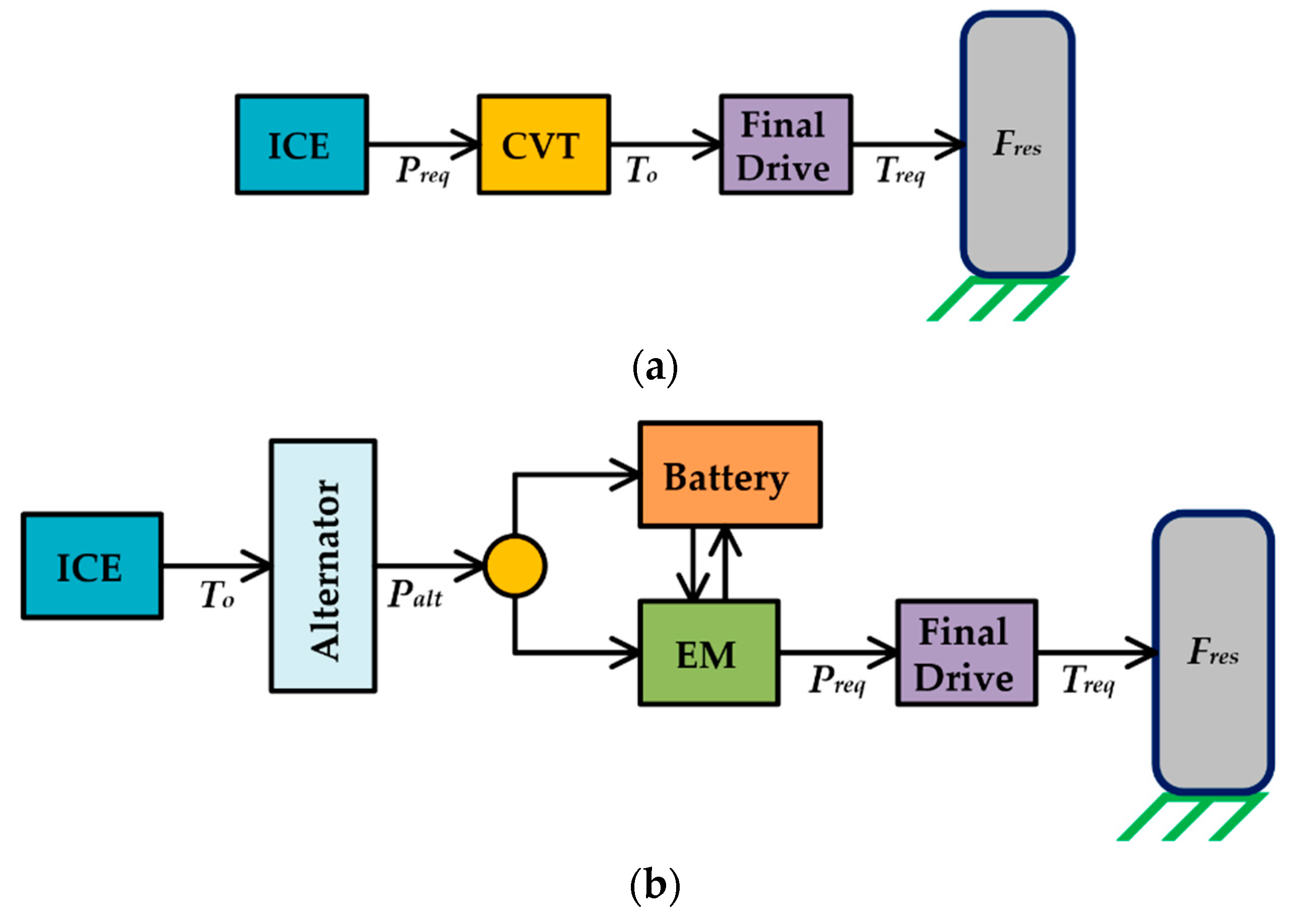
Figure 2.
Control algorithm for the series-hybrid vehicle.
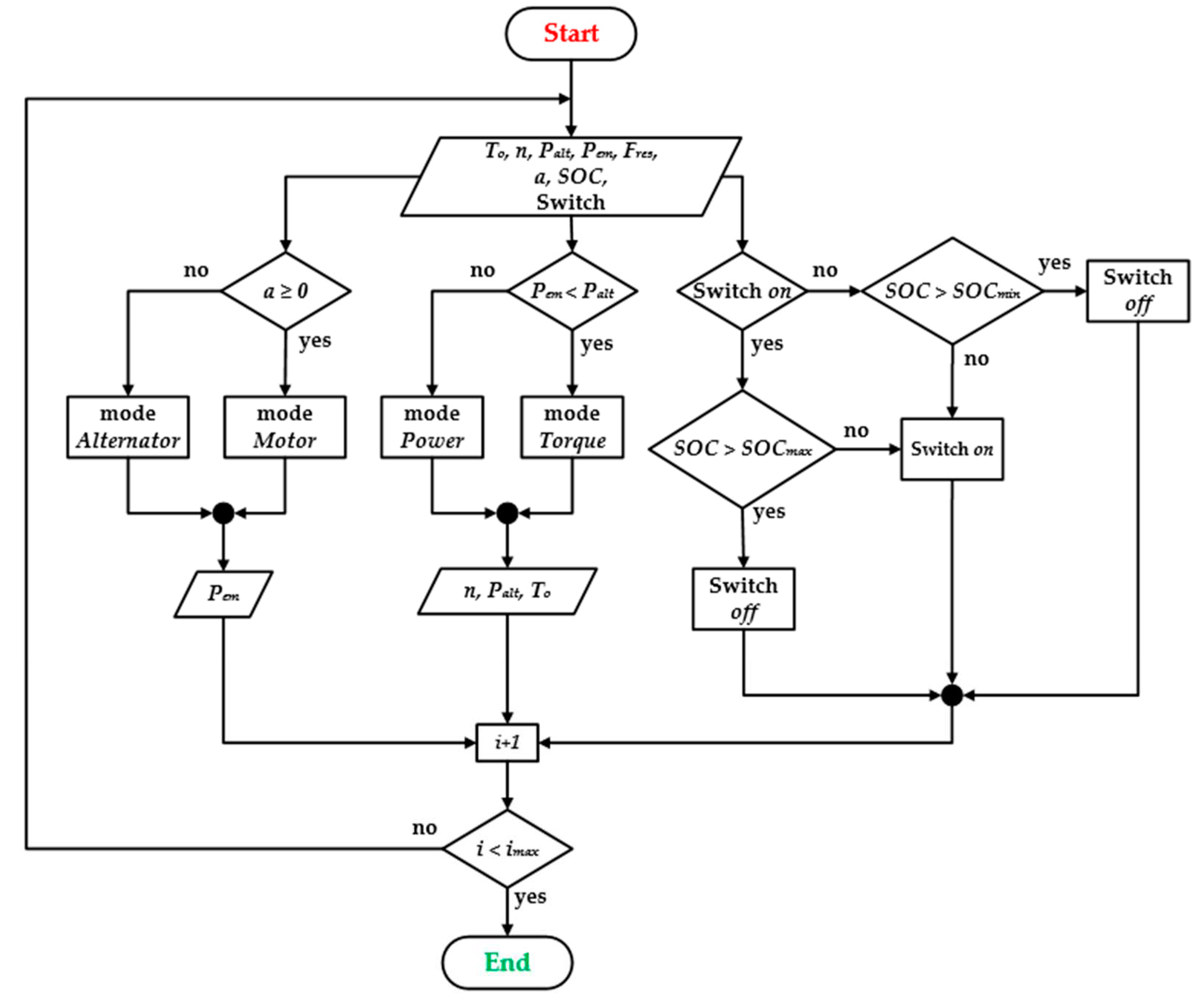
Figure 3.
Control algorithm for the series-hybrid vehicle: longitudinal model of the tractor (a); tractor architecture model (AVL Cruise) (b).
Figure 3.
Control algorithm for the series-hybrid vehicle: longitudinal model of the tractor (a); tractor architecture model (AVL Cruise) (b).
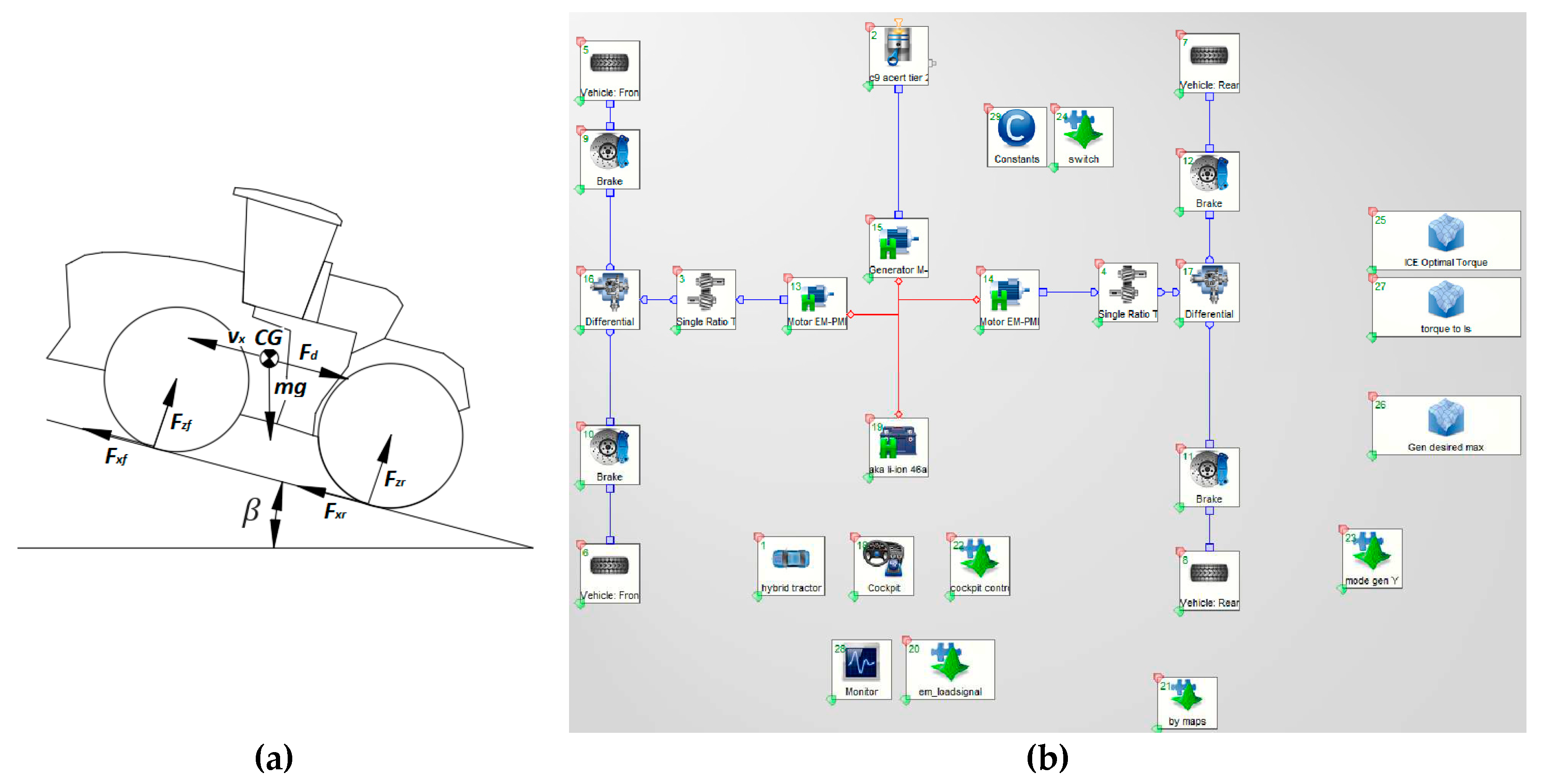
Figure 4.
Hybrid Operational Cycle.
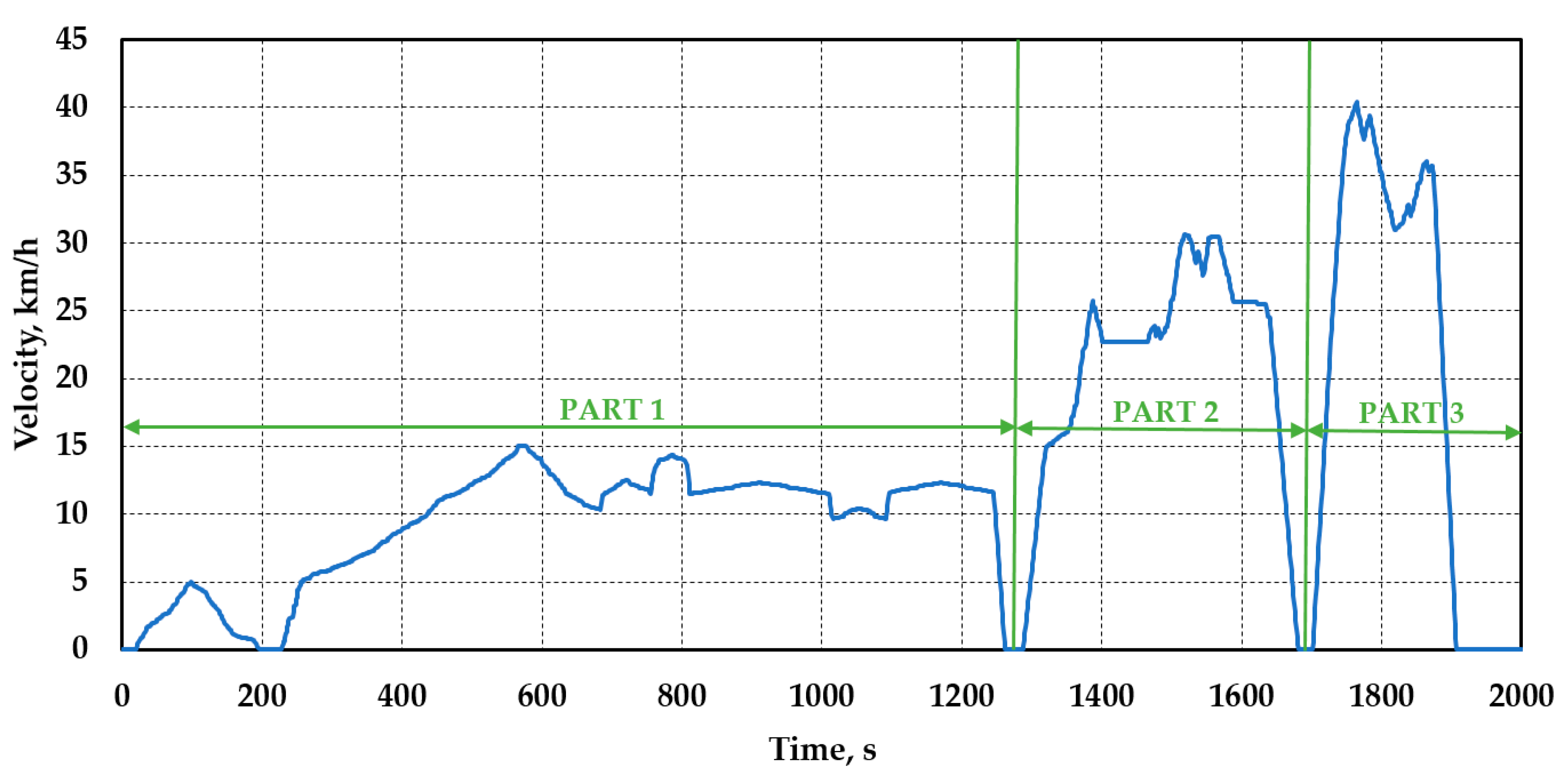
Figure 5.
Power generated by the ICE during the Extended Hybrid Operational Cycle.
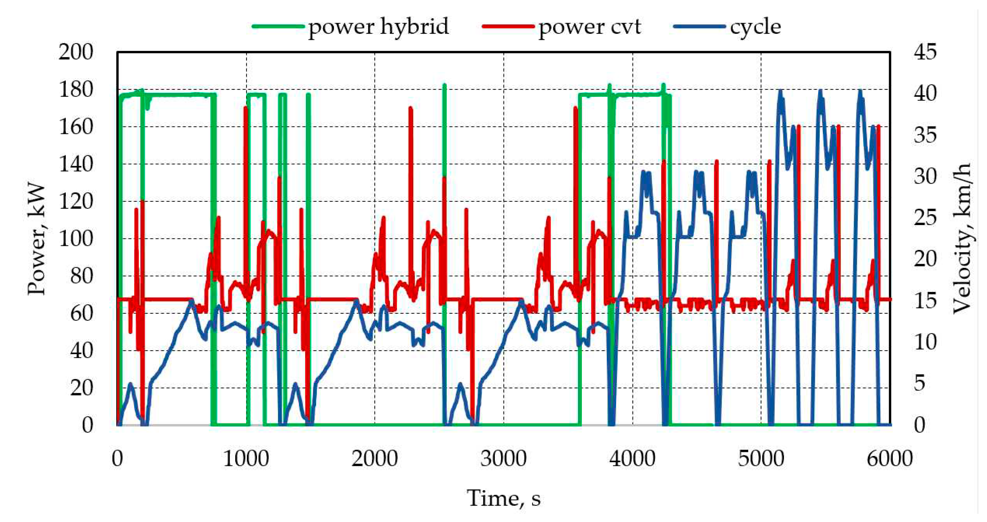
Figure 6.
Specific fuel consumption during the EHOC.
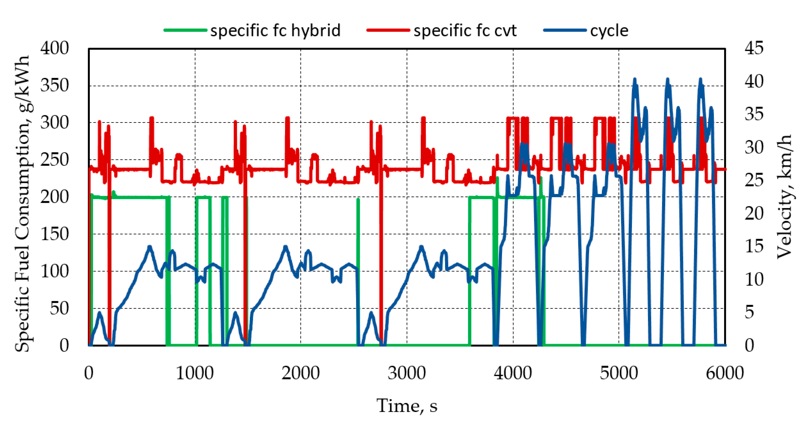
Figure 7.
Fuel consumption by mass during the EHOC.
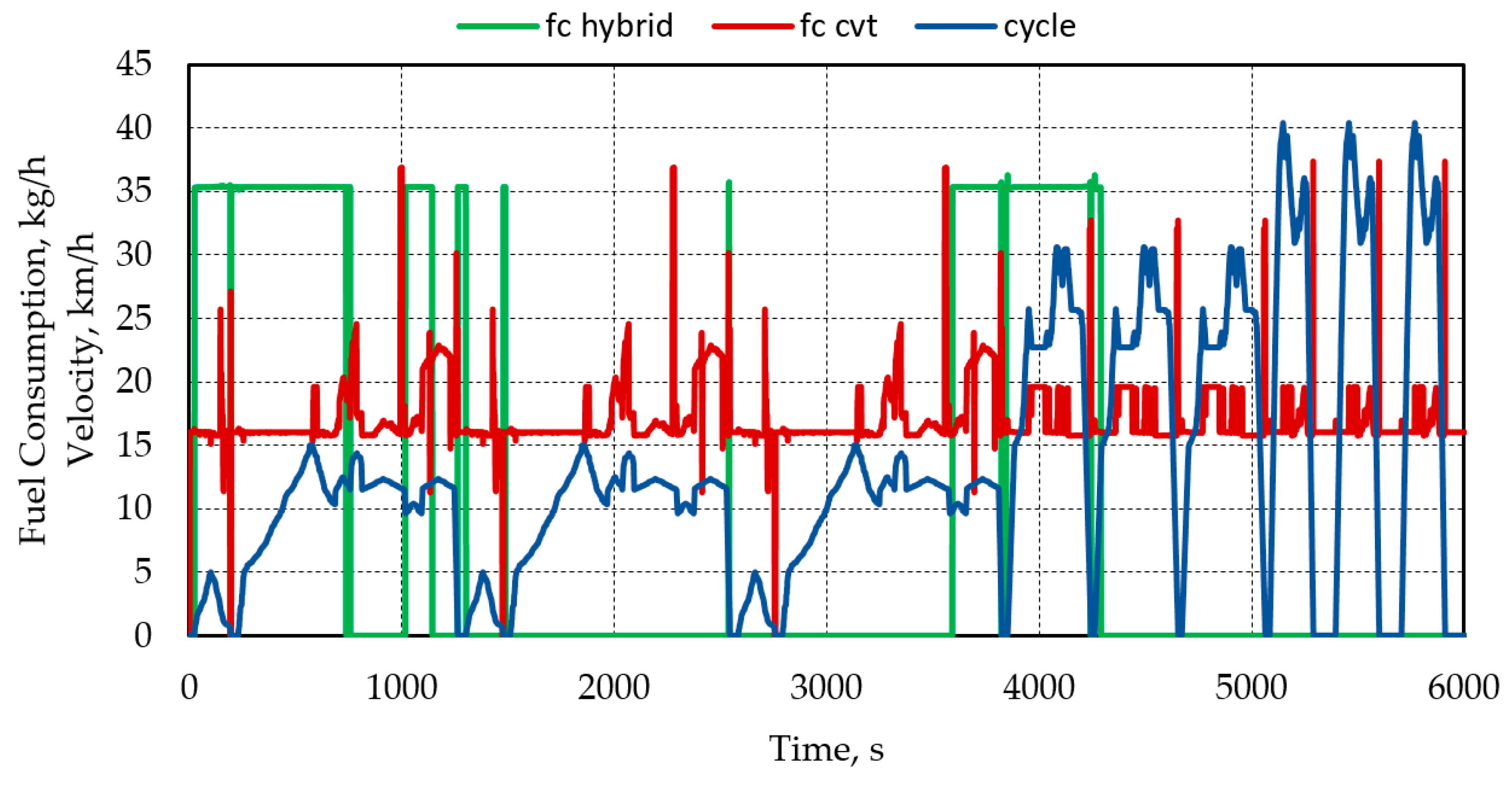
Figure 8.
Power generation and fuel consumption throughout the EHOC.
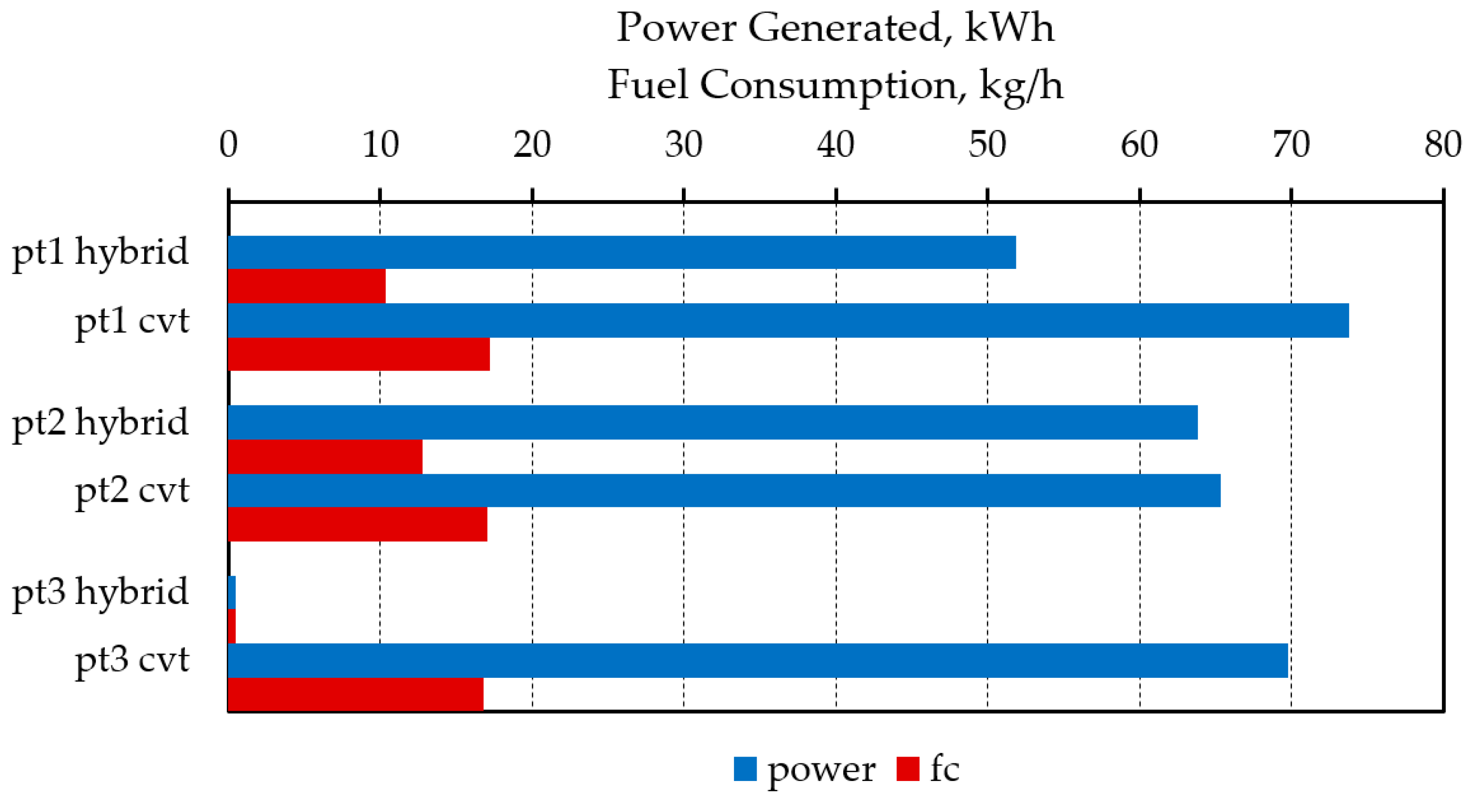
Figure 9.
Hybrid vehicle’s state of charge and regeneration.
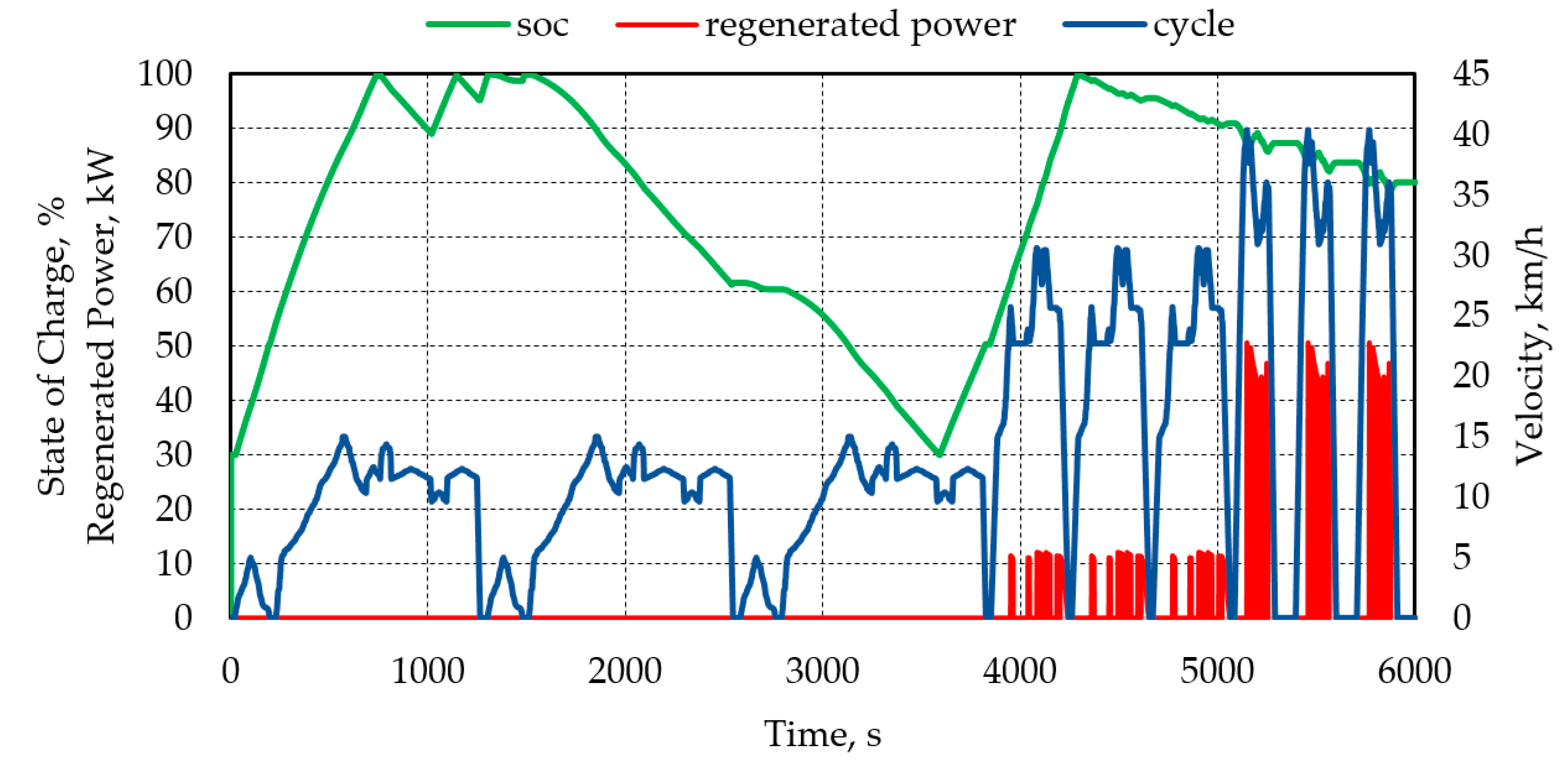
Figure 10.
Battery power distribution over the EHOC.
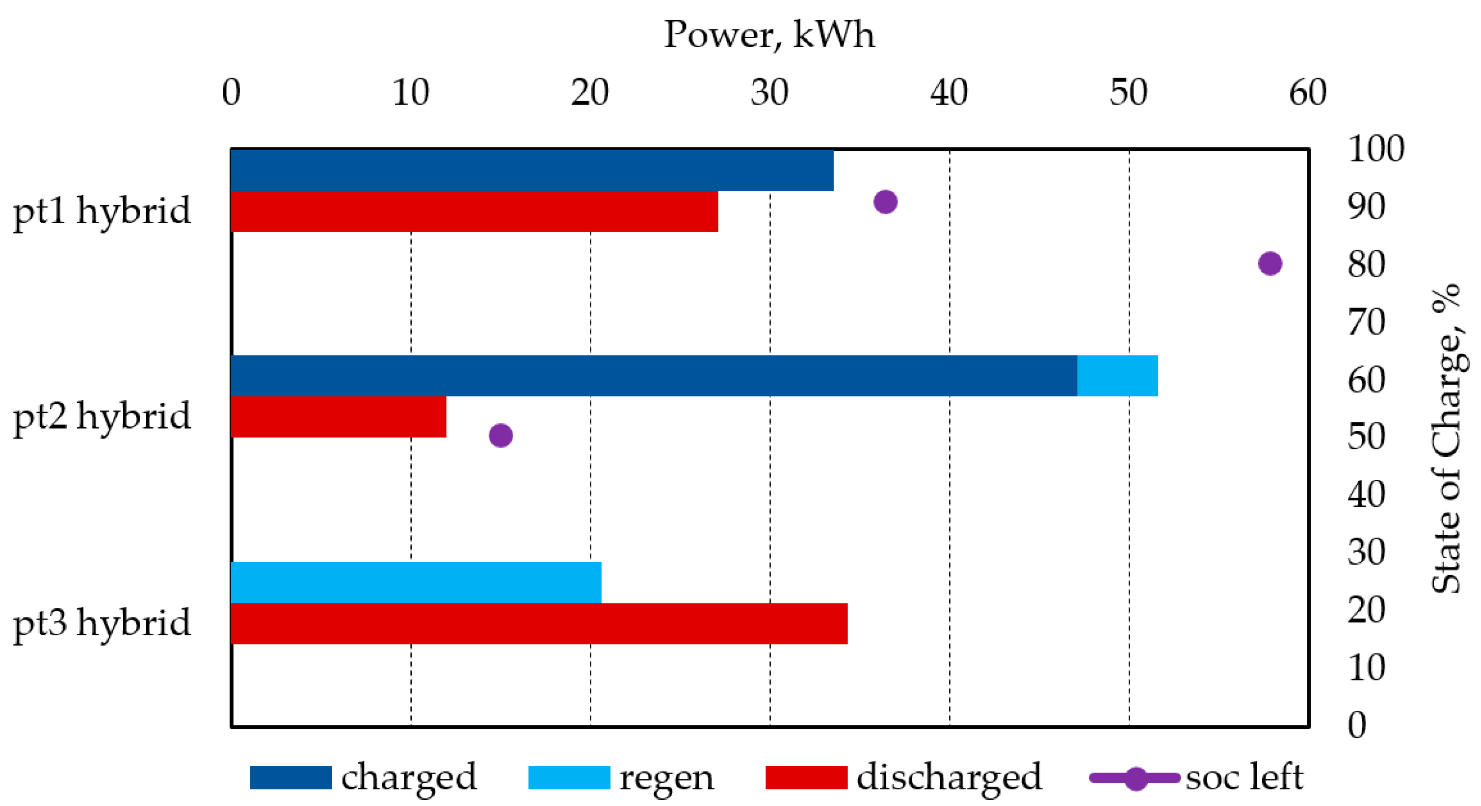
Figure 11.
Power consumption and fuel consumption throughout the EHOC.
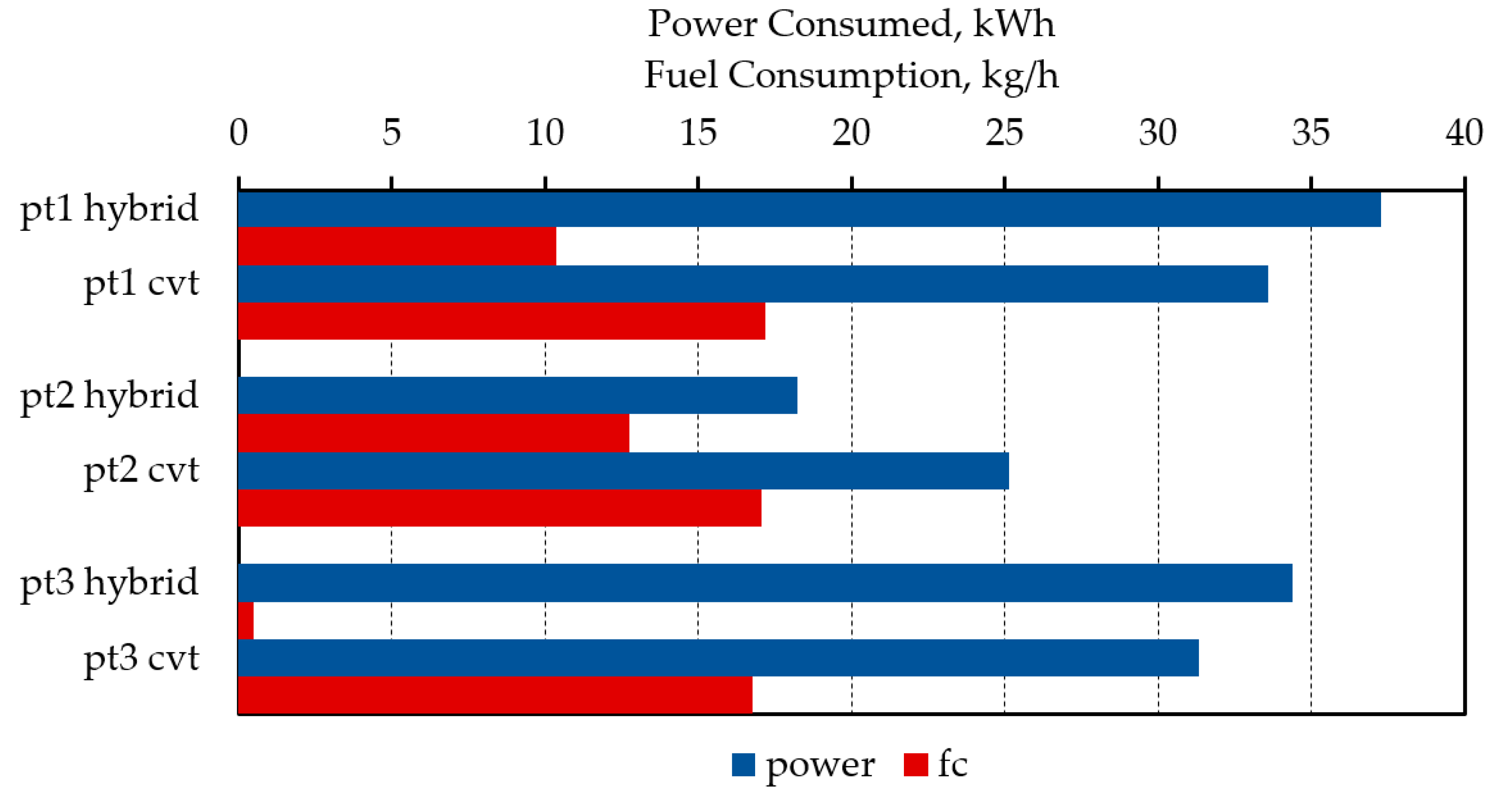
Figure 12.
Battery power distribution over the EHOC.

Table 1.
Road properties that were defined.
| Cycle pt. | Rolling resistance | Tire friction |
|---|---|---|
| Part 1 | 0.09 | 0.6 |
| Part 2 | 0.02 | 0.6 |
| Part 3 | 0.02 | 0.75 |
Disclaimer/Publisher’s Note: The statements, opinions and data contained in all publications are solely those of the individual author(s) and contributor(s) and not of MDPI and/or the editor(s). MDPI and/or the editor(s) disclaim responsibility for any injury to people or property resulting from any ideas, methods, instructions or products referred to in the content. |
© 2023 by the authors. Licensee MDPI, Basel, Switzerland. This article is an open access article distributed under the terms and conditions of the Creative Commons Attribution (CC BY) license (http://creativecommons.org/licenses/by/4.0/).
Copyright: This open access article is published under a Creative Commons CC BY 4.0 license, which permit the free download, distribution, and reuse, provided that the author and preprint are cited in any reuse.


