Submitted:
27 June 2023
Posted:
28 June 2023
You are already at the latest version
Abstract
The present work presents and discusses an analysis of the floor types of Villa of Diomedes (Pompeii archaeological park in the Campania region, Italy) both from architectural, archaeological, and structural point of view. In particular, the geometrical structural parameters of different floor types and the rules used by ancient builders to design them are investigated by means of interdisciplinary research. Link between structural-based assumptions, archival sources, geometric survey, in situ visual inspections and the archaeological information make it possible to define the geometrical structural parameters of eleven-barrel vaults, three wooden floors and three sloped wooden roofs (buried and collapsed during the Vesuvius eruption). A specific study of the barrel vaults is presented to investigate the relationships between the main vaults’ structural parameter. Furthermore, a comparison between the vaults’ dimensions obtained from surveys and those produced by the literature formulations from the 15th to the 20th centuries concerning masonry-vault designs is presented and discussed.
These analyses carried out in the framework of Villa of Diomedes interdisciplinary project was very useful to interpret the fabrication of the Villa and to make a reconstruction of 3D model as it probably resulted to be the fateful year of 79 A.D.
Keywords:
Floor types
; interdisciplinary approach
; Pompeii archaeological park
; Villa of Diomedes
; design formulations
; barrel vaults
; wooden floors
1. Introduction
If historical and architectural heritage constructions are to be protected and safeguarded for the today’s communities and the future generations, their conservation, maintenance, and restoration should comply with the principles of authenticity and material compatibility [1]. The conservation project therefore clearly needs an interdisciplinary knowledge approach to acquire historical data; perform a detailed analysis of the construction techniques adopted; and define any modifications that occurred over a building’s lifetime [2,3]. The study of floor types (arches, vaults, and wood beams) in the field of historical and cultural heritage constructions is often missing due to the lack of detailed information on such structures, especially in the case of ruins. Thus, the study of such components that play a crucial role in the analysis of structural behaviour of constructions, is particularly fascinating, but also very complex. It involves the investigation of the ancient design criteria and raw materials used in the past as well the cross link of different sources of data, combining different fields like archaeology, architecture, geology, topography, the conservation sciences, and structural engineering.
Cultural heritage documentation research, based on the investigation of archival sources when available, is one of the key tasks within the knowledge-process framework. Archival sources provide information on excavated remains and the interventions carried out on them up to the present day. The analysis of standing buildings at archaeological sites requires refined methods that use accurate investigations of archival sources and in-situ surveys. This would enable researchers to acquire fundamental information on the construction methods and practices used by ancient builders. This step is crucial for defining the type of intervention and relevant materials to be used in a conservation, maintenance, restoration, or partial reconstruction process.
Roman architecture used arches extensively, with large ashlars of stones or bricks arranged radially with thin mortar joints. Concrete is also used for the vaults; as concern the Pompeii archaeological park concrete vaults were firstly detected in Stabian Baths, built around the second half of the second century b.C. [4,5,6,7,8,9]. This technique was used to create simple geometric shape with a structural behavior like a monolith [10,11]. Several approaches were adopted over time to improve their structural performance. Starting from the first century AD, Roman builders added brick ribs to vaults composed of rubble and mortar masonry to avoid the cracking that would have otherwise occurred [10]. Furthermore, they arranged materials according to their unit weight: stone blocks and tiles for the lower parts and light inert conglomerate for the upper sections. They then also produced lightweight vaults using empty amphorae [12,13]. The first examples of amphorae in the vaults occur in the second century (i.e. Magazzini Traianei and Villa alla Vignaccia). They were initially used to save construction materials. A strong use of amphorae for lightening vaults can be found in the Minerva Medica temple (first half of the 4th century AD) [11,13,14].
Ancient builders improved their competence over time by way of trial and error [16,17]. This enabled them to define some rules of thumb based on the geometrical relationships between vault components, e.g., span, rise and crown thickness and the width and height of piers. Nowadays, such rules have almost been forgotten, in relation to the design of floor types [10].
The first tenet only appeared in Renaissance treatises [18] and only concerned the abutment widths of Gothic structures [19]. Rules were used extensively in the 18th century to validate new theories related to arch stability [16,17]. In this period, static analyses based on wedge theory were applied to the field thanks to the work of de la Hire and others [20]. After the studies described in [19,20,21,22,23], the methods used to investigate the structural behaviour of vaulted buildings were essentially based on geometric proportions. However, their structural forms continued to be established using various rules of thumb, because builders lacked knowledge of the mathematics and mechanics required to understand and perform static analyses [23].
Roman builders made extensive use of masonry vaults, but often preferred wooden structures for floors and roofs due to their high strength-to-weight ratio [24]. Two main typologies of wooden floors were used in Roman times and described by Vitruvius in De architectura in the I century B.C. : i) contignatio and contabulatio (or coaxatio), made of a single or double layer of beams and wooden planks and ii) lacunar (or laquear), made of two perpendicular rows of beams. The name contignatio came from the Roman word tignum (beam) and referred to the wooden structure, while contabulatio (or coaxatio) refers to wooden floorboard, sometimes made of two layers (coaxatio transversa) to obtain a stiffer structure. Lacunar was used to cover largest areas (span longer than 5 m) or for decorative purpose, to create a coffered ceiling [4,5,24].
Different evidence of wooden floors was found in ancient Roman cities in Campania and in several cases, they were made according to Vitruvius’ instructions [7,17,18,19]. The cross-section of the beams resulted circular, sometimes rough lengthwise cut logs, or rectangular [17]. Beams were generally positioned orthogonally to the walls, in the direction of the smallest side of the area to be covered. Spans were generally quite short, i.e. not exceeding 4.50 m length, probably because shorter beams were more easily procured, less expensive and easier to handle [17]. The beams were generally positioned at a constant distance with a spacing computed as a function of the cross-section dimensions, the span, and the bearing load. Evidence in Pompeii and Herculaneum archaeological parks shows the ancient floor were very rigid due to short spans and large cross-section. According to different surveys performed at the Pompeii archaeological park and Herculaneum, the beam spacing generally varied from about 30cm to about 45 cm while beams socket varied from about a minimum of 12 cm to a maximum of 34 cm [4,5,24,25].
Vitruvius also discussed the type of timbers available for construction [26]. A first classification of the wood of different trees according to density, heaviness and hardness was provided by Theophrastus (book 5 of Historia Plantarum). Pliny provided additional evidence of the use of wood, focusing on woodworking.
This paper focuses on the floor types surveyed in the Villa of Diomedes (Pompeii archaeological parkin the Campania region, Italy). The study aims to clarify and understand technical choices made by ancient builders when designing such structural members. The study has been carried out within the framework of the Villa of Diomedes multidisciplinary project. This is coordinated by the Ecole Normale Supérieure – PSL University (UMR 8546), with the support of: the Centre Jean Bérard (Naples, Ecole Française de Rome - CNRS); the INRIA (Institut National de Recherche en Informatique et Automatique, Center de Paris-Rocquencourt); and the Pompeii archaeological park [27]. The project was launched in 2012 and it became part of the ANR RECAP programme, completed in 2019 (RECAP: Rebuilding after an earthquake: ancient experiences and innovations in Pompeii).
The paper first describes the Villa of Diomedes (section 2). Section 3 presents the methodology adopted to identify and investigate the horizontal structural most significant parameters. Section 4 analyses and discusses the data collected data on 19 horizontal structures and presents a comparison between their characteristics and those retrieved using literature design (i.e. from the 15th to the 20th centuries) formulations. It also discusses the wooden floor characteristics to investigate on beam dimensions and to determine the criteria adopted by Roman builders when designing such structural member. That has allowed to frame the analysis of floor types in an overall view of the villa from the archaeological, architectural, engineering point of view. In fact, different tasks were undertaken to analyse the history of life cycle of the villa as described in section 3. Furthermore, the study may significantly improve the knowledge of the floor types and provides a useful tool for technicians involved in the analyzing and understanding the structural behavior of ruins.
2. Historical notes and description of the Villa of Diomedes (Pompeii archaeological park)
The Villa of Diomedes is located in the north-west area (the so-called suburban area, 200 m north of the Herculaneum Gate) of the Pompeii archaeological parkin the Campania region (Figure 1). Other three Villas are located in the area: Villa of Cicero, Villa of the Mosaic Columns and Villa of the Mysteries. The four Villas are connected by the Sepulchres Street, which starts from Porta Ercolano and ends at the Villa of the Mysteries. The studies on the urban context highlighted that the three Villas, Villa of Diomedes, Villa of Cicero and Villa of the Mysteries are arranged along parallel axis in North-South and East-West directions [28,29]. On the other hand, the orientation of Sepulchres Street does not correspond to such axis. Therefore, it seems that the construction of the street is posterior to the construction of the three Villas. This hypothesis is also supported by several archaeological studies. Those studies allowed to highlight the closure of a door in Mercurius street and a simultaneous opening of Porta Ercolano once Sepulchres Street was built. The urban evolution of the city is discussed in [30]. According to [30], the urban reorganization could be justified in the logic of a deep political and institutional mutation, as the period of deduction of syllanienne colony. Even if this hypothesis seems very truthful, it remains very difficult to know the transformations suffered by Villa of Diomedes after the construction of Sepulchres Street.
The Villa was one of the first buildings discovered in Pompeii during the excavation campaigns between 1771 and 1775, and it was one of the largest private constructions found there. Initially known as “suburban Villa”, it owes its current name to the tomb of Marcus Arrius Diomedes, which was discovered in 1774 close to the Villa’s entrance. The current configuration of the Villa is a consequence not only of its complex alterations over time [27], but also the damage that occurred after the 79 A.D. Vesuvius eruption that completely covered the ancient city of Pompeii.
Nowadays, the Villa consists of three levels: i) ground; ii) garden; and iii) cryptoporticus. It was possible to gain access through the monumental entrance on Sepulchres Street. As is typical of Roman Villas, the peristyle could be reached via the monumental entrance. There is a triangular portico with a frigidarium and kitchen on the east side of the peristyle, while there are residential rooms and the apsed room on the south side, and the tablinum on the west side.
The Vesuvius eruption led to the collapse of the terrace that was built as the roof for the four-side portico surrounding the garden. There are servile rooms on the north side of the peristyle, while two staircases located on the north and south sides of the ground level, respectively, allow access to the garden level. The garden level is comprised of vaulted rooms on the east side and a four-sided portico that enclosed the garden. The triclinium is in the center of the garden.
3. Floor identification’s methodology
3.1. Vaults
In-situ surveys were required to identify the geometrical structural parameters of the Villa’s vaults. To this end, data from geometrical surveys and topographical measurements were integrated with historical sources [31,32,33,34,35] and evidence from archaeological studies. It is not always easy to identify floor types using only visual inspections. Indeed, in relation to vaults, different cases can be found in the ruins of archaeological sites in general (Figure 2): (a) undamaged vault; (b) undamaged vault in a room that has not been fully excavated; (c) partially collapsed vault; (d) collapsed vault). If possible, geometrical structural data in relation to vaults can be entirely derived from in-situ surveys, with or without the support of ortho-images and topographical data.
A typical example of case (a) in the Villa of Diomedes is set out in Figure 3 . The data produced by a geometrical survey of the vaults in their current condition were validated using ortho-images (Figure 3 - a1) and archival sources (Figure 3 - a2). This made it possible to achieve the complete restitution of the Villa’s geometrical structural parameters (Figure 3 - a3).
An example of case (b) was found in the Villa at the cryptoporticus level. As a result of an incomplete excavation, it was not possible to determine the distance between the vault intrados and the floor level directly. According to data retrieved from the topographical features, it was possible to conclude that the excavation work ended at different levels of the Villa’s cryptoporticus level (Figure 3 - b1, b2). It was possible to establish the actual floor level based on the number of stairs in the two staircases that enabled access to the cryptoporticus and the topographical survey data on the floor levels above sea level (a.s.l.). As a result, by cross-linking information sources using geometrical survey and topographical data, and by adding information provided by ortho-images, it was possible to determine the geometrical structural parameters of the vault (Figure 3 - b3).
A partially collapsed vault (i.e., case c) was found at the garden level. In this case, it was not possible to measure the distance between the floor and intrados of the vault keystone, either in situ or from the archival sources [35,36,37,38]. However, it was possible to determine the vault’s geometrical structural parameters (Figure 3 - c2) using a graphical construction based on the information provided by the ortho-image (Figure 3 - c1) of the remaining part of the vault (i.e., the ruins of the collapsed vault).
Finally, a collapsed vault (case d) at ground level was also detected in the Villa. In this case, a trace of curved plaster and the presence of holes on an orthogonal wall (Figure 3 - d1) enabled to assume the existence of a false vault and an original horizontal structure comprised of wooden beams. This assumption was validated by the analysis of available archival sources, as set out in (Figure 3- d2). These information sources made it possible to define the geometrical parameters of the false vault (Figure 3- d3) which had no structural function.
3.2. Wooden floors
In-situ surveys are the first stage when seeking to identify the geometrical structural parameters of wooden. For the former, data provided by visual inspections, archival sources and evidence from archaeological studies are crucial. Ancient wooden structures in Pompeii collapsed and were buried due to the Vesuvius eruption. Nevertheless, traces of wooden floors and sloped wooden roofs are still notable in in-situ surveys [33]. Indeed, rows of rectangular holes in walls to support floor beams can be detected by visual inspection in several buildings. The definition of beams’ cross-section dimensions is, however, a challenging task. Although Roman builders commonly used rectangular cross-sections, carbonized wooden-beam ruins and imprint evidence at the archaeological park of Herculaneum have demonstrated that circular beams were often used and placed in rectangular holes [11]. Furthermore, the holes were larger than the minimum to ensure support for the beams for the following reasons [10]: (a) because a gap between the beam and the masonry was required to ensure beneficial ventilation and avoid the generation of condensation at the wood-masonry interface; (b) the holes were also used to host temporary structures used in the construction phases; and (c) due to installation-procedure requirements. It was only possible to establish the actual beam dimensions in traces of conglomerate.
As concern the top layer of the structure it could be either a simple wooden floor or a thick pack consisting of conglomerate screed and a stone or brick pavement. The screed was made of several layers depending on the function of the structure: intermediate level or planar roof. As reported in De Architectura, Liber Septimus 1, 2, 3, it was necessary to apply a layer of ferns (filex) or straw (palea) over the timber planks before laying the conglomerate to protect them from lime and humidity. After that, the first layer of the screed consisted of a mortar, traditionally made of lime, sand and pozzolana, mixed with lightweight, loose and medium-sized stone material such as lapillus, the statuminatio. It had a thickness of about 10 cm and it was used both for intermediate levels and for the first floor over the ground.
The second layer was the main part of the screed, the so-called rudus, and it consisted of a conglomerate based on finer loose material, generally lapillus, in a lime mortar. According to Vitruvius, the rudus should have a thickness of about 22 cm (dodrantis: three-quarters of a Roman foot) and it consists of three parts of stone material and a part of binder. The final layer was the nucleus used to support the pavement with a thickness of about 11 cm (digitorum senum: six Roman inches). Thus, the screed had a significant thickness, rigidity and weight, reaching about 45-50 cm. This thickness was higher in roofs due to the insertion of additional layers with the function of insulating and stiffening the floor. Indeed, ancient builders sometimes realized a waterproofing layer between the rudus and nucleus of planar roofs, consisting of bipedal bricks laid on a layer of mortar with the edges protected by infiltration by an olive oil coating. At the end, they created the flooring with a slope of more than 1% that further increased the thickness of the element [4].
Furthermore, both material traces and archival sources must be investigated to determine any sloped wooden roof structures. For example, in the Villa of Diomedes, the rectangular peristyle at the ground level was composed of sloped wooden roof structures, as determined by surveys and studies conducted by Mazois [34] (Figure 4a) and La Vega [35] (Figure 4b). The traces of two holes (Figure 4c) on the south wall at the 4.65 m level, and of holes on the colonnade at the 3.40 m level (Figure 4d), clearly confirm the original sloped configuration of the roof (see Figure 4e).
4. ANALYSIS OF THE FLOOR TYPES
During this study eleven masonry vaults, one false vault, three wooden floors and two sloped wooden roofs were identified. Their locations are portrayed in Figure 5a, b and c at the ground, garden and cryptoporticus levels, respectively.
4.1. Vaults
The masonry vaults detected at the Villa are of the barrel type and, according to the visual inspection of the partially collapsed vault still visible in room No. 53 at the garden level, are composed of pozzonalic mortar, with lava, travertine cruma and tuff stones. As concern the construction characteristics of the piers, they are made with yellow and grey tuff as the other walls of the garden level.
The ortho-image, along with the geometrical survey, enabled to determine the vaults’ main geometrical structural parameters: span (s); rise (r); radius (R); crown thickness (St); pier width (W); and impost (H) (Figure 6).
The dimensions of the barrel vaults and relevant ortho-images are depicted in Figure 7: two barrel vaults at the ground level (Figure 7a); eight barrel vaults at the garden level (Figure 7 b, d, e); and one vault at the cryptoporticus level (Figure 7c).
The data collected on the barrel vaults at the Villa are reported in Table 1. The pier width, W, is provided for each of the two piers supporting the vaults, W1 and W2. Table 1 shows that the barrel-vault spans, s, range between 1.98 m and 4.02 m and r/s ratios between 0.21 and 0.43. According to the ratio, r/s, the barrel vaults are defined as semi-circular (r/s = 0.5) or segmental (r/s < 0.5) [15]. Furthermore, the segmental vaults are characterized as either shallow (r/s ≤0.25), semi-shallow (0.25< r/s ≤0.40), or deep (r/s>0.40). The sample of data collected concerns the segmental vaults: five shallow-arch, five semi-shallow arch, and one deep-arch.
In the case of the ruins at the park, it is very difficult or impossible to determine the geometrical structural parameters of the vaults, especially St and W (see Figure 2). Indeed, St could not be easily identified, because of the total or partial collapse of the vault or the difficulty of measuring both the intrados and extrados levels. The pier width, W, meanwhile, was difficult to determine for the basement room. Accordingly, to help technicians involved in analysing the behaviour of ruins at archaeological parks, the relationship between structural parameters retrieved from the Villa of Diomedes are discussed in the following. In particular, the analysis aims to evaluate the relationship between the r/s (the easiest parameters to determine by an in-situ survey) and St/s, St/r and H/Wmin ratios. Figure 8 reports the relationships between these parameters, as well as the scheme of a barrel vault and the geometrical structural-parameter ratios used to classify it (Figure 8a). The data found from surveys of Pompeii are plotted with reference to shallow, semi-shallow and deep-arch vaults (Figure 8b–d). The use of interpolation functions enabled to determine the best fitting trend and the relevant equations and R-squared coefficients. These are reported in Figure 8b, c, d. The graphs in Figure 8b and c reveal quite good agreement between the actual survey data and the predictions made using the proposed formulations (R2=0.83 and R2=0.66 for St/s – r/s and St/r – r/s relationships, respectively); in contrast, there was less accuracy for the H/Wmin – r/s relationship (R2=0.12). The percentage error of the predicted St/r, St/s and H/Wmin, according to the equation reported in Figure 8 (Vpred) with respect to the data observed in the surveys (Vexp), was also calculated using the Mean Absolut Percentage Error (MAPE):
Using interpolation functions, the MAPE was equal to 14%, 11%, and 34% for the predicted St/s, St/r, and H/Wmin, respectively. Note that the observational point related to the deep-arch vault has been excluded from the interpolation.
Discussed below is a comparison between actual data from the Villa and the geometrical structural parameters provided by the literature for available design formulations. The existing -literature design formulations from between the 15th and 20th centuries have been collected in [30,31,32,33,34] and are summarized in Table 2 for shallow and deep-arch vaults, respectively.
Such formulations mainly provided correlations between St as a function of s or R, and the pier width, W, as a function of s. The latter formulation indicates that the pier width can be designed as 1/4 - 1/10 of the span, s.
Figure 9a and b report the St-s relationships obtained using the literature design formulations summarized in Table 2 for shallow and deep-arch vaults, respectively. The actual data provided by surveys at the Villa of Diomedes for shallow (blue points), semi-shallow (red points) and deep-arch vaults (yellow points) are also reported in Figure 9a and b. Figure 9a shows that the St dimensions found for the semi-shallow arch vaults are, in some cases, greater than those obtained using the literature design formulations reported in Table 2. In contrast, the shallow-arch vaults mostly show the St between the upper and lower bounds of these formulations.
Such results are clearly shown in Figure 9c, which reports the envelope of literature design formulations and the comparison with actual data. It also shows that the best fit between the survey data and literature design formulations is that proposed by Breymann in 1853 [32] (red dotted line) for semi-shallow arch vaults.
Note that literature design formulations are mainly related to arches/vaults made up of ashlars while those found in Pompeii are made of concrete with a strong mortar leading to an exceptional degree of toughness which could generate membrane forces in the structural elements and relevant limited thrust on the piers. But the way, it is interesting to note that, according to the data shown in Figure 9, Roman builders used criteria to design barrel vaults that were very similar to those formulated several centuries later. This clearly confirms and evidences the advanced technical levels attained by Roman builders.
4.2. Wooden floors
The original presence of wooden floors at the Villa was assumed based on the analysis of holes in the masonry bearing walls. In particular, it was possible to assess the presence of wooden floors in rooms 63, 66 and 73 at the garden level (see Figure 5b). An aligned row of holes is clearly visible in Figure 10a1, which shows room 63. According to survey outcomes, it was possible to assume the presence of an original one-way ((i.e., with beams in one direction only) wooden floor made of rectangular beams of 0.30 m x 0.35 m (wide, height). The spacing between them was, on average, 0.65 m (center to center), with a 0.57 m-thick conglomerate slab. The beams were 3.30 m long and the anchoring length into the walls was 0.3 m at both ends (see Figure 10a2, a3).
Another one-way wooden floor was detected in room 66 (Figure 10b1). This floor had a rectangular plan and, according to the traces of the beam holes (Figure 10b1), we made the assumption that the beams were 3.25 m long, with square cross-sections of 0.20 m x 0.20 m (wide, height) spaced, on average, 0.45 m apart (Figure 10b2).
Finally, a third wooden floor was examined in room 73, because traces of beam holes were observed in the two orthogonal south and east walls (Figure 10c1, c2). Accordingly, it was assumed that the room was originally covered by a wooden floor formed of two orthogonal and overlapping sets of beams (i.e., a two-way slab). Survey data led to the following assumptions in terms of the dimensions of the structural members: for the north-south oriented beams - 0.15 m x 0.20 mm (width, height) spaced 0.45 m apart, with a total length of 3.63 m; for the upper east-west oriented beams - 0.15 m x 0.15 m (width, height) spaced an average of 0.45 m apart, with a total length of 5.25 m (Figure 10c3).
To investigate the criteria adopted by Roman builders when designing the beams’ dimensions, we considered the actions of the following dead-load layers on the floor beams according to the specifications reported in [44]:
(a) a first layer of timber planks; (b) a second layer of conglomerate slab (composed of a first layer of lime mortar, with lightweight medium-sized stone gravel, a second layer of lime mortar and finer loose material, and a final layer supporting the floor); and (c) a floor layer. The thickness of the roofs was greater than that of the intermediate floors, because: a second layer of transversal timber planking was commonly inserted in the roofs; and the conglomerate slab was composed of additional layers for the purposes of insulation (i.e., a waterproofing tile layer and flooring with a slope of more than 1%) and to increase the slab stiffness. According to the literature information [32,44] and in-situ records, the thickness of the dead-load layers (i.e., timber planks, conglomerate and flooring) were assumed to be: 0.06 m, 0.57 m and 0.05 m for the roofs (room 63, total thickness of 0.68 m), and 0.03 m, 0.43 m and 0.05 m for the floors (rooms 66 and 73, total thickness of 0.51 m).
Two assumptions have been made to account for the conglomerate density, : 7 kN/m3 in the case of light pumice aggregate; and 14 kN/m3 for heavy pumice. Several wood species were commonly used in Pompeii’ constructions such as silver fir, poplar, cypress, chestnut and oak. According to studies carried out in [24,45] it was decided to consider chestnut for the following analysis. According to [46], chestnut timber was assumed to have a density of 6 kN/m3, while the dead load resulting from the flooring was assumed to be equal to 0.60 kN/m2. In order to assess the maximum stress in the beams due to the original dead loads, fmax,DL, and the stress ratio, defined as the ratio between fmax,DL and the bending wood strength, fm, the wood properties were assumed according to [43]: the bending wood strength, fu, =41.1 MPa and the Young’s modulus, Em, =12.85 GPa. The maximum stress in the beams due to the original dead loads, fmax,DL, was calculated according to the adopted structural schemes: (a) a simple supported-beam scheme for the one-way floors (rooms 63 and 66), fmax,DL = (qDLL2/8)/W, with a qDL total dead load and a W elastic section modulus; and (b) for the two-way floor (room 73), and according to the Winkler model, beams on elastic supports in the east-west direction and a simple supported-beam scheme in the orthogonal direction (north-south).
Table 3 summarizes the main floor structural parameters along with the stress ratio, fmax,DL/fm, which was computed assuming either light or heavy pumice aggregate as the conglomerate density.
The outcomes related to the one-way intermediate floor (room 63) show stress ratios of 2%-3% due to dead loads; these were 6%-10% for the one-way roof floor (room 66). Such an increase was due to the different function of the structure, which served as a terrace rather than an intermediate floor, and to the greater cross-section used in room 63 than in room 66, even for similar spans (3.33 m versus 3.63 m). In the case of the two-way floor in room 73, the stress ratios ranged from 5%-8% in the north-south beam and 15% to 26% in the east-west beam.
In addition to the stress ratio, the maximum beam deflection, f, is also reported in Table 5. In particular, the ratio between maximum deflection and beam length (i.e. floor span) is reported.
5. The Interdisciplinary knowledge process.
That has allowed to frame the analysis of floor types in an overall view of the villa from the archaeological, architectural, engineering point of view. In fact, different tasks were undertaken to analyse the history of life cycle of the villa. The first investigation involved the existing architectural structures using both archaeology of construction and structural engineering methods. Several in situ inspections together with non-destructive tests were carried out to establish a shared technical-scientific and historical-critical path. The achievement of a detailed knowledge level and an accurate information useful for structural analyses performed according to current standards requirement reported in [2,3] have been obtained. The knowledge acquired has been enriched by research on the historical archives of Museo Archeologico Nazionale di Napoli, MANN and Palazzo Caramanico in the Reggia di Portici.
The acquired data allowed to carry out both 3D model of the state of building to the present day, (i.e. ruins) and 3D model of the Villa as it probably resulted to be the fateful year of 79 A.D when the Vesuvius eruption buried the ancient Roman city of Pompeii under a thick carpet of volcanic ash. The last one was very useful to understand the organization of floor types of the Villa of Diomede.
An interdisciplinary knowledge process has been carried out for the Villa of Diomedes to evaluate the building from both technical-scientific and historical-critical point of view. The main problem for the knowledge of historic building deals with the impossibility to retrace the evolution of the building during its life cycle. Therefore, accurate historical research, geometrical-architectural and structural surveys, and damage detection and structural criticalities are crucial steps necessary to perform refined analyses and interpretation of historical building techniques. The structural engineering has proved to be a good technical support to the notions acquired on the field by archaeologists, as it allows to re-read with scientific methods the ancient design criteria of the ancient Roman art and to evaluate the technical value of "traditional" materials.
The first step of the interdisciplinary study involved a comprehensive approach to the knowledge of the building by means of in-situ visual inspections supported by documentary sources. The whole building has been inspected to discover the architectural and historical asset. Particular attention has been paid to the relationship between the building and the urban context, to the building materials and techniques.
Furthermore, in a second stage, the building itself has been assumed as an historical document. Therefore, the Villa of Diomedes has been analysed as a “material culture” by means of method of archaeological reading used in conjunction with the graphic and photographic survey of the building. The analysis of the Villa as material culture along with the study of building techniques, paintings styles, and structural cracking allowed to identify six construction phases [27].
Other repair, restoration and maintenance interventions were carried out during and after the excavations up to present days. During the excavation the building was maintained to the state of discovery carrying out only repair and consolidation interventions, as reported in the journal of excavation [36]. After excavation several interventions were carried out due to simple maintenance or to reconstruct collapsed portion of the building [47]. An important restoration occurred in 1946 [48], after the US bombardment which affected the southern perimeter wall of the buildings. Finally starting from 2020 the PAP launched a project to restore the monument as part of Grande Progetto Pompei [49].
Known the construction phases from the original configuration until the last one, the axonometric projection of the Villa at state of ruins (Figure 11) has been performed. The model of the Villa of Diomedes has been defined by means of the drawings of the three floors. Their geometrical dimensions have been retrieved in some cases by direct in situ inspections, or when impossible by direct measurements, since the Villa is in state of ruin, by using information provided by ortho-images or by means of the historical sources. The photographic survey was carried out to obtain a support for the archaeological, iconographic, architectural, and engineering studies. Different surveys have been carried out to create a 3D photogrammetric model of the Villa of Diomedes. According to such a model it was possible to obtain: i) the photographic acquisition by a drone of the entire Villa; ii) the image processing using the PMVS software developed by Jean Ponce (Willow team, ENS) and Yasutaka Furukawa (University of Illinois). It was used in conjunction with software to calibrate photographic devices (to calculate their intrinsic parameters and positions), such as the Bundler free software from the University of Washington, and Apero of National Geographic Institute, IGN. The software took as input the photographic acquisition and gives as outputs a cloud of three-dimensional points.
Moreover, an overall model of the Villa has been realized in its topographical context. It makes possible to visualize the Villa in its environment and to georeference it in a Geographic Information System (GIS) context.
The studies carried out showed evidence of architectural elements that no longer exist. For example, in Figure 12a are shown the evidence of wooden floor (beams holes highlighted with red box) and stairs (highlighted with red line).
Based on this evidence, it has been hypothesized the configuration before 79 A.D. eruption of the wooden floor, the staircase. and the upper part of the wall. The configuration is highlighted in red in Figure 12b.
Similar studies were carried out on the whole villa. In case of room without floor, it was possible to hypotheses that the original vaults probably collapsed due to the weight of pyroclastic material deposited following the 79 A.D. eruption. Unfortunately, there are no traces or information about their failure mode.
The use of 3D model was necessary to analyse and validate the hypotheses related to the Villa structural characteristics. Indeed, the ruins only partially allow to define the whole structural characteristics of the Villa. The interdisciplinary study consisted in the combination of different source of data and hypotheses on the Villa development over its life; the 3D model was used as a tool to assess the effectiveness and soundness of such hypotheses on the basis of the structural consistency of the model.
An initial crucial step to begin the 3D modelling has been the evaluation of the quote of the horizontal structure. To this aim topographical measurements carried out in 2015 by the architect G. Chapelin within the “Grande Progetto Pompei” [50] were used. The procedure led to some difficulties since the topographical points are related to the sea level, but in some areas, the measurements are related to the quote to which the excavation has been stopped instead of the real quote. Therefore, to reach a reliable outcome it has been necessary to integrate the information of the topographical measurement with the historical sources and to do a continuous comparison with the archaeological studies. Different levels of precision and reliability were used. Generally, the reconstruction offers a high degree of uncertainty because data related to the modern renovation phase of the Villa should be carefully detected and excluded while parts that are no longer visible (i.e., as the first floor, the horizontal covering structures of the ground floor, and the towers in south and north sides of the four-sided portico in Villa of Diomedes) should be defined and correctly inserted in the actual configuration.
The 3D model of the Villa as it probably resulted to be the fateful year of 79 A.D is reported in (Figure 13. 3D model reconstruction at 79 A.D: (a)plan; (b) overall view b).
In this procedure, particular care should be paid to horizontal structures that are obviously no more found at Pompeii archaeological park. Thus, a specific study of floor types was carried out in the present paper, focusing on the identification of barrel vaults and wooden floors. Several field surveys and post field analyses were carried out to identify the geometrical structural parameters of the floor types of the Villa and understand their structural behaviour [1,2]. The following sections illustrate the methodology adopted to identify the floor types and relevant geometrical structural parameters.
6. Conclusions
Using an interdisciplinary approach combining engineering and archaeology, this paper presents and discusses an analysis of the geometrical structural parameters of different floor types in the standing remains of the Villa of Diomedes (Pompeii archaeological parkin the Campania region of Italy). The interdisciplinary approach has been carried out by means of knowledge process of buildings assessed with historical-critical analysis, geometric survey, in situ visual inspections.
The use of different sources of data made it possible to define the characteristics of eleven-barrel vaults, three wooden floors and three sloped wooden roofs.
The geometrical structural parameters of the Villa’s masonry vault and wooden floors (buried and collapsed during the Vesuvius eruption) were obtained by linking structural-based assumptions with archival sources.
The study of the barrel vaults at the Pompeii archaeological park has enabled to highlight the relationships between the main vaults’ structural parameters, which may be of assistance to technicians analyzng the behaviour of ruins at archaeological parks. An increasing trend was observed in terms of the relationships between the ratios r/s (rise to span) and St/s (crown thickness to span) and St/r (crown thickness to rise) and H/Wmin (height to minimum pier width) for both shallow (r/s ≤0.25) and semi-shallow arch vaults (0.25< r/s ≤0.40); this trend was not confirmed for deep-arch vaults (r/s>0.40), although limited data are available in this field. Interpolation functions to predict the data observed by surveys produced MAPEs of 14%, 11%, and 34% for the predicted St/s, St/r, and H/Wmin, respectively (R2 = 0.83, R2 = 0.66, and R2 = 0.32, respectively).
A detailed analysis was conducted to obtain literature formulations from the 15th to the 20th centuries concerning masonry-vault designs. The analysis also compared the vaults’ dimensions obtained from surveys with those produced by the formulations. The comparison showed that the semi-shallow arch vaults (0.25< r/s ≤0.40) detected in the Villa of Diomedes were designed using slightly more conservative rules than design formulation set out in the literature; in contrast, the dimensions of the shallow-arch vaults (r/s ≤0.25) were in line with those produced by literature design formulations. The structural dimensions of the vaults found in the study reflected those obtained in studies in the 20th century, which clearly demonstrates Roman builders’ advanced level of understanding of the vaults’ structural behaviour. The study of the wooden floors allowed to define beam dimensions and, according to the assumptions made on the dead loads, to determine the maximum stress in the beams, computed as the ratio between fmax,DL and the bending wood strength, fm. The outcomes showed that a stress ratio in the range 2% – 10% was observed for the one-way floors, but this varied between 15% and 26% for the two-way floors. In the case of the one-way floors, the fmax,DL/fm ratio was lower for the intermediate floors (range 2% – 3%) than the roofs (range 6% – 10%), because the latter had greater thicknesses than the former in order to provide a proper insulation system.
The acquired data have allowed to carry out both 3D model of the ruins and 3D model of the Villa as it probably resulted to be the fateful year of 79 A.D.
Although further data on ruins are clearly required to validate the outcomes of the present work, the findings can nevertheless be used as a comprehensive preliminary tool to assist technicians involved in the challenging tasks of analysing structural behaviour and defining conservation, maintenance, or restoration interventions on historical and architectural heritage buildings.
Acknowledgments
The authors would like to pay special thanks to the Parco Archeologico of Pompeii (PAP), in particular the General Director, Prof. Massimo Osanna. We are also grateful to Grete Stefani and Annalisa Capurso for their constant support and collaboration during our field activities. Finally, thanks go to Hélène Dessales, manager of the Villa of Diomedes Project, Guilhem Chapelin for the architectural study and plan of the Villa, Julian Cavero for the cartographic support, Thomas Crognier for the ortho-images and photos, Florence Monier for the archival sources, and Francesca Autiero for the work developed in her PhD thesis.
References
- DPCM 09/02/2011, Linee Guida per la valutazione e riduzione del rischio sismico del patrimonio culturale con riferimento alle norme tecniche per le costruzioni (D.M. 14 gennaio 2008), Supplemento ordinario alla G.U. n. 54 del 26 febbraio 2011, Rome, Italy, (in Italian).
- Rufolo, S.A. , Rovella N., Arcudi A., Crupi V., Majolino D., Osanna M., Pace R., Pantuso A., Randazzo L., Ricca M., Ruggieri N., Venuti V., La Russa M. F., 2020. New insights to assess the consolidation of stone materials used in built heritage: the case study of ancient graffiti (Tituli Picti) in the archaeological site of Pompeii. Heritage Science. Vol 8, Issue 1, 2020.
- ICOMOS/ISCARSAH Committee. 2005. Recommendations for the Analysis, Conservation and Structural Restoration of Architectural Heritage.
- Adam 2014: J. P. Adam, L’arte di costruire presso i romani. Materiali e tecniche, Longanesi, XI edition, 2014. Mettre versione inglese.
- C. F. Giuliani, L’edilizia nell’antichità, Carocci editore, Roma 2006, p. 79-83, 98-101, 117-139, 181-184.
- Blake, M.E. Ancient Roman Construction in Italy from the Prehistoric Period to Augustus. Carnegie Institut: Washington, DC, USA.
- Lugli, G. 1957. La Tecnica Edilizia. Rome: G.
- MA, 1971. MacDonald, W.L., The Architecture of the Roman Empire, i, rev. ed., New Haven, 1982, 3–19.
- Lynne Lancaster, Roman Engineering and Construction The Oxford Handbook of Engineering and Technology in the Classical World Edited by John Peter Oleson Print Publication Date: Dec 2009 Subject: Classical Studies, Greek and Roman Archaeology, Material Culture Studies Online Publication Date: 2012. [CrossRef]
- Lancaster Lynne, C. Concrete Vaulted Construction in Imperial Rome: Innovations in Context, Cambridge, 2007.
- Lancaster 2015:, L. Lancaster, Innovative vaulting in the architecture of the Roman Empire. 1st to 4th centuries CE, Cambridge, 2015.
- Aveta 1987:, A. Aveta, Materiali e tecniche tradizionali nel napoletano. Note per il restauro architettonico, Napoli, pp. 105-111, 125- 129, 164-170, 1987.
- Marcello Spanu, “L’impiego di anfore nelle volte romane e tardo-antiche: distribuzione e modalità,” Daidalos: Studi e ricerche del Dipartimento di Scienze del Mondo Antico 8 (2007): 185–223.
- Auguste Choisy, L’art de bâtir chez les Romains (Ducher, 1873).
- Huerta, S. Arcos, bóvedas y cúpulas; Instituto Juan de Herrera. Escuela.
- Benvenuto, E. An introduction to the history of structural mechanics; Springer: New York, 1991. [Google Scholar]
- Kurrer, K.E. The History of the Theory of Structures: From Arch Analysis to Computational Mechanics; Ernst & Sohn: Berlin, 2008. [Google Scholar]
- Derand F., L’architecture des voûtes, ou l’art des traits et coupe des voûtes, [...] par François Derand, S. Cramoisy, Paris 1643.
- Viollet-le-Duc, E., 1844-1847: De la construction des édifices religieux en France, depuis le commencement du christianisme jusqu'au XVIe siècle. Annales archéologiques 1-6.
- De La Hire, P. 1712. Sur La Construction Des Voûtes Dans Les édifices. In Mémoires l’Académie R. Des Sci. Paris. 70-78.
- Couplet, P. , De la poussée des voûtes, “Mémoires de l’Académie Royale des Sciences”, année 1729, Paris 1731, pp. 79-117.
- Bélidor, B.F. de, La science des ingénieurs dans la conduite des travaux de fortification et d’architecture civile, C.-A. Jombert, Paris 1729.
- Oliveira, D.V.; Lourenço, P.B.; Lemos, C. Geometric issues and ultimate load capacity of masonry arch bridges from the northwest Iberian Peninsula. Engineering Structures 2010, 32, 3955–3965. [Google Scholar] [CrossRef]
- Ulrich, R.B. Contignatio, Vitruvius, and the Campanian Builder, in American. Journal of Archaeology 1996, 100, 137–151. [Google Scholar] [CrossRef]
- M.P. Guidobaldi, D. Camardo, D. Esposito, E. Tommasino, I solai e gli architravi lignei dell’antica Ercolano, in: P.G. Guzzo, M.P. Guidobaldi (Eds.), NUOVE RIC. ARCHEOL. NELL’AREA VESUVIANA (SCAVI 2003-2006), «L’ERMA» di BRETSCHNEIDER, Rome, 2007: p. 3–6.
- P. Gros (ed.) Vitruvius De Architectura Liber Decem, 44 Einaudi, Torino, 1997.
- Dessales, H. ed., The Villa of Diomedes in Pompeii : the making of a Roman villa, with the contributions of M. Borgongino, C. Boust, M. Carrive, J. Cavero, G. Chapelin, A. Coutelas, R. Deiana, G. Depeyrot, H. Dessales, F. Lorenzoni, G. De Martino, M. Di Ludovico, J. Dubouloz, A. d’Harcourt, É. Letellier-Taillefer, A.M. Mauro, G. Manfredi, F. Marchand-Beaulieu, A. Maigret, A. Milanese, C. Modena, F. Monier, A.-B. Pimpaud, J. Ponce, A. Prota, E. Rizzo, A. Rossi, A. Santoriello, A. Tricoche and M. R. Valluzzi, forthcoming, éd. Hermann, Paris, 2020.
- Maiuri, R. Pane, La Casa di Loreio Tiburtino e la Villa di Diomede in Pompei, Rome, 1947.
- Mingazzini, P. Un criterio di datazione della Villa di Diomede a Pompei, ArchCl, 1, 1949, p. 202-204.
- Zevi, F. , Urbanistica di Pompei, in La regione sotterrata dal Vesuvio: Studi e prospettive. Atti del convegno internazione (11-15 novembre 1979), Naples, 1982, p. 353-365.
- Morelli, Francesco (between 1791 and 1796): Painting reproduction (H. 64.7-L.40.0cm in Museo Archeologico Nazionale di Napoli, Archivio dei disegni storici, ADS 1152.Villa Diomedes Project, Images database. Available online: https://villadiomede.huma-num.fr/bdd/images/20040. Visited on 25/03/2020.
- Lo Manto Giuseppe, (between 1809 and 1811): Painting reproduction. in Museo Archeologico Nazionale di Napoli - Archivio dei disegni storici ADS 1147 Villa Diomedes Project, Images database. Available online: https://villadiomede.huma-num.fr/bdd/images/20022.
- Ruggieri, N. (2017). Carpenteria di legno dei tetti e dei solai interpiano a Pompei nel I secolo D.C. Restauro Archeologico, 25(2), 4-19. [CrossRef]
- Mazois, François (between 1809 and 1811): Section Bibliothèque Nationale de France, Département des Manuscrits, RESERVE GD-12 (E)-FT4. Villa Diomedes Project, Images database. Available online: https://villadiomede.huma-num.fr/bdd/images/20643. Visited on 25/03/2020.
- La Vega, Francesco (between 1774 and 1775): Section (H. 48.0-L. 33.0 cm) Museo Archeologico Nazionale di Napoli, Archivio dei disegni storici, ADS 1133. Villa Diomedes Project, Images database. 2020. Available online: https://villadiomede.huma-num.fr/bdd/images/20075. . Visited on 25/03/2020.
- Fiorelli, G. 1860-64 Rapporti di scavo settimanali PAH.1, Naples, 1860, pp. 249-282, 4/3/1775.
- Dessales, H. Dessales H., Tricoche A., A palimpsest monument: The corpus of graphic and photographic archives from the eighteen to twenty-first centuries in The Villa of Diomedes in Pompeii: the making of a Roman villa, Dessales, H. ed., with the contributions of M. Borgongino, C. Boust, M. Carrive, J. Cavero, G. Chapelin, A. Coutelas, R. Deiana, G. Depeyrot, H. Dessales, F. Lorenzoni, G. De Martino, M. Di Ludovico, J. Dubouloz, A. d’Harcourt, É. Letellier-Taillefer, A.M. Mauro, G. Manfredi, F. Marchand-Beaulieu, A. Maigret, A. Milanese, C. Modena, F. Monier, A.-B. Pimpaud, J. Ponce, A. Prota, E. Rizzo, A. Rossi, A. Santoriello, A. Tricoche and M. R. Valluzzi, forthcoming, éd. Hermann, Paris, 2020, pp. 27-66.
- Masci, M.E. 2016, La fortuna visiva di Pompei. Archivio di immagini e testi dal XVIII al XIX secolo: l’esperienza di un progetto in-progress, in «Bollettino di Informazioni del Centro di Ricerche Informatiche per i Beni Culturali», Pisa 2002, n. 2, pp. 83-107. ISSN 1126-6090.
- Alberti, Leon Battista. On the Art of Building in Ten Books; The MIT Press: London, Cambridge Mass, 1992. [Google Scholar]
- Albenga, G. Lessons on bridges. Vol. 1, Torino; 1930 [in Italian]. Técnica Superior de Arquitetura Madrid.
- Proske, D.; van Gelder, P. Safety of historical stone arch bridges; Springer, 2009. [Google Scholar]
- Brencich, R. Morbiducci Masonry arches: historical rules and modern mechanics. Int J Arch Her 2007, 165–189. [Google Scholar] [CrossRef]
- Serrano-Lopez, R.; Urruchi-Roj, J.R.; Martinez-Martinez, J.A. The shallow arch: a step towards bridges styling in the early 19th century. Eng Struct 2018, 167, 84–95. [Google Scholar] [CrossRef]
- P. Gros (ed.), Vitruvio. De architectura, Liber Septimus, 2–3, 5–7. Einaudi, Torino, 1997.
- Ulrich, R.B. Roman woodworking; Yale University Press: New Haven (CT) & London, 2007. [Google Scholar]
- Faggiano, B.; Grippa, M.R.; Marzo, A.; Mazzolani, F.M. Combined non-destructive and destructive tests for the mechanical characterization of old structural timber elements. Y. Itoh, T. Aoki, 3rd International Conference on Advances in Experimental Structural Engineering, San Francisco, 15-16 October; Springer-Verlag, 2009; pp. 657–666. [Google Scholar]
- Dessales H., Monier F Excavation, removals, and restorations in The Villa of Diomedes in Pompeii : the making of a Roman villa, Dessales, H. ed., with the contributions of M. Borgongino, C. Boust, M. Carrive, J. Cavero, G. Chapelin, A. Coutelas, R. Deiana, G. Depeyrot, H. Dessales, F. Lorenzoni, G. De Martino, M. Di Ludovico, J. Dubouloz, A. d’Harcourt, É. Letellier-Taillefer, A.M. Mauro, G. Manfredi, F. Marchand-Beaulieu, A. Maigret, A. Milanese, C. Modena, F. Monier, A.-B. Pimpaud, J. Ponce, A. Prota, E. Rizzo, A. Rossi, A. Santoriello, A. Tricoche and M. R. Valluzzi, forthcoming, éd. Hermann, Paris, 2020, pp. 77-90.
- Letter to the Ministero della Pubblica Istruzione, Direz. Gentile, Antichità e Belle Arti di Roma 7/2/1946, prot. n.391: “Restauro ai muri danneggiati della Villa di Diomede e chiusura dei relative varchi dall’esterno”.
- Dessales H., Monier F., Restoration project in The Villa of Diomedes in Pompeii: the making of a Roman villa, Dessales, H. ed., with the contributions of M. Borgongino, C. Boust, M. Carrive, J. Cavero, G. Chapelin, A. Coutelas, R. Deiana, G. Depeyrot, H. Dessales, F. Lorenzoni, G. De Martino, M. Di Ludovico, J. Dubouloz, A. d’Harcourt, É. Letellier-Taillefer, A.M. Mauro, G. Manfredi, F. Marchand-Beaulieu, A. Maigret, A. Milanese, C. Modena, F. Monier, A.-B. Pimpaud, J. Ponce, A. Prota, E. Rizzo, A. Rossi, A. Santoriello, A. Tricoche and M. R. Valluzzi, forthcoming, éd. Hermann, Paris, 2020, pp. 91-102.
- Available online: http://pompeiisites.org/grande-progetto-pompei/.
Figure 1.
Urban framework of the Pompeii archaeological park (blue), the location of the Villa of Diomedes (yellow).
Figure 1.
Urban framework of the Pompeii archaeological park (blue), the location of the Villa of Diomedes (yellow).
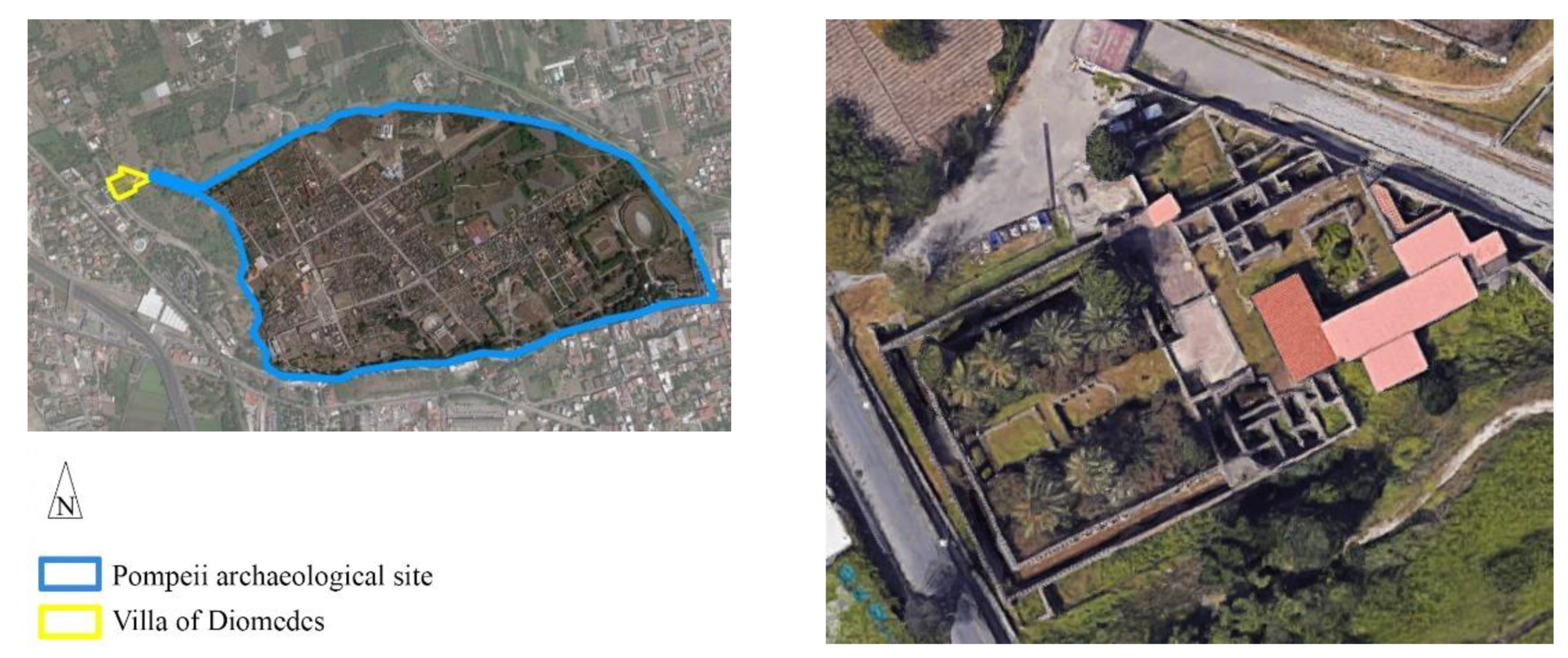
Figure 2.
Different layout of vault of Villa of Diomedes: (a) undamaged vault; (b) undamaged vault in a room that has not been fully excavated; (c)partially collapsed vault; (d)collapsed vault.
Figure 2.
Different layout of vault of Villa of Diomedes: (a) undamaged vault; (b) undamaged vault in a room that has not been fully excavated; (c)partially collapsed vault; (d)collapsed vault.
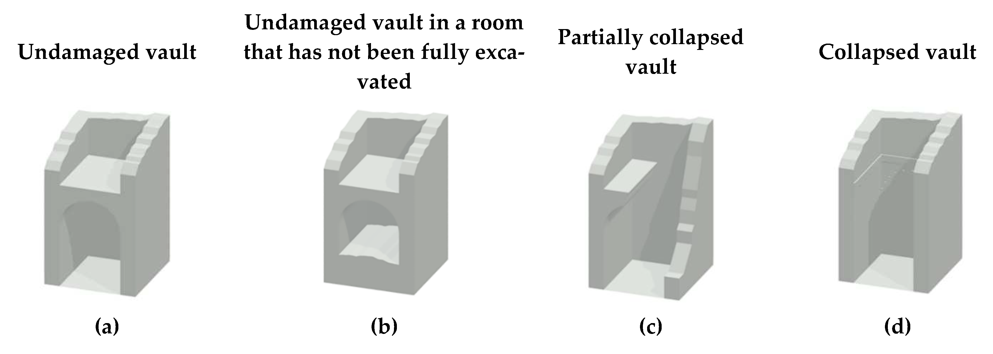
Figure 3.
Case a) undamaged vault: (a1) wall ortho-image; (a2) archival sources of Morelli, Francesco (between 1791 and 1796): painting reproduction (H. 64.7-L.40.0cm) [31] and (a3) geometrical structural parameters; case b) undamaged vault in a room that has not been fully excavated: (b1) a fully excavated zone close to the staircase located on the north-east side; (b2) a zone that has not been fully excavated on the south-east side; (b3) wall ortho-image and geometrical structural parameters; case c) partially collapsed vault: (c1) the standing vault; and (c2) the geometrical structural parameters; and case d) collapsed vault: (d1) south and east wall; (b); (d2) archival sources of Lo Manto Giuseppe: painting reproduction [32]; and (d3) geometrical parameters of the false vault [dimensions in m] (photo: Thomas Crognier).
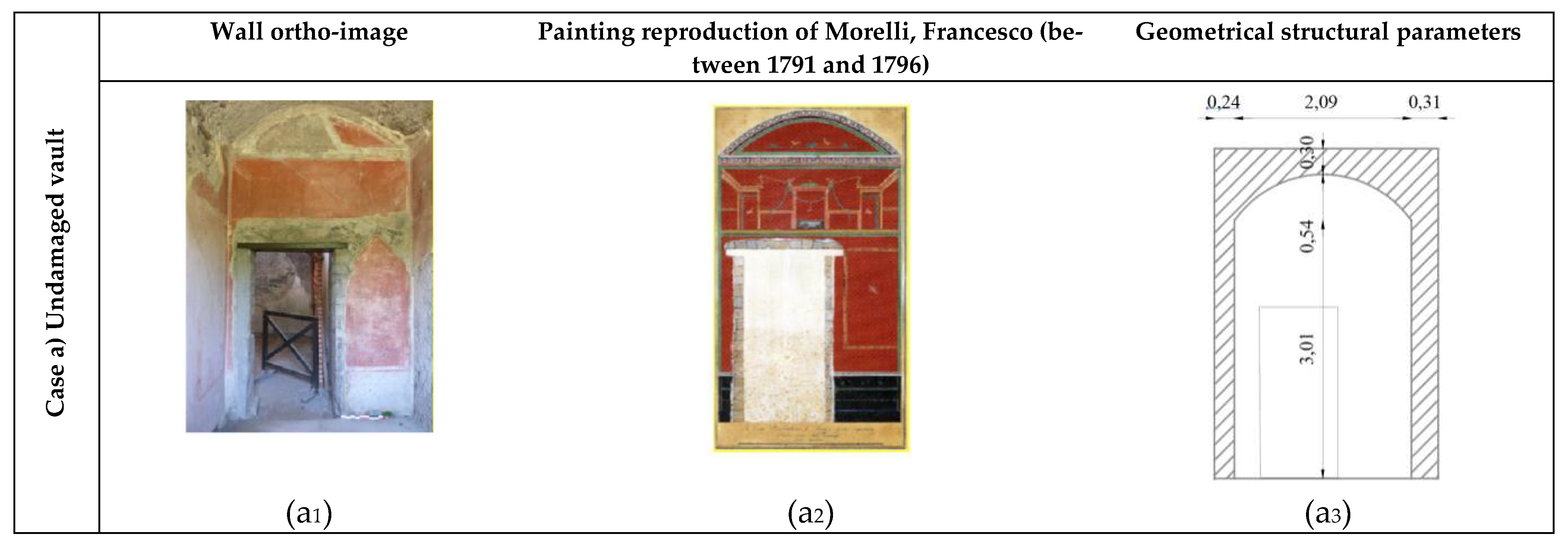
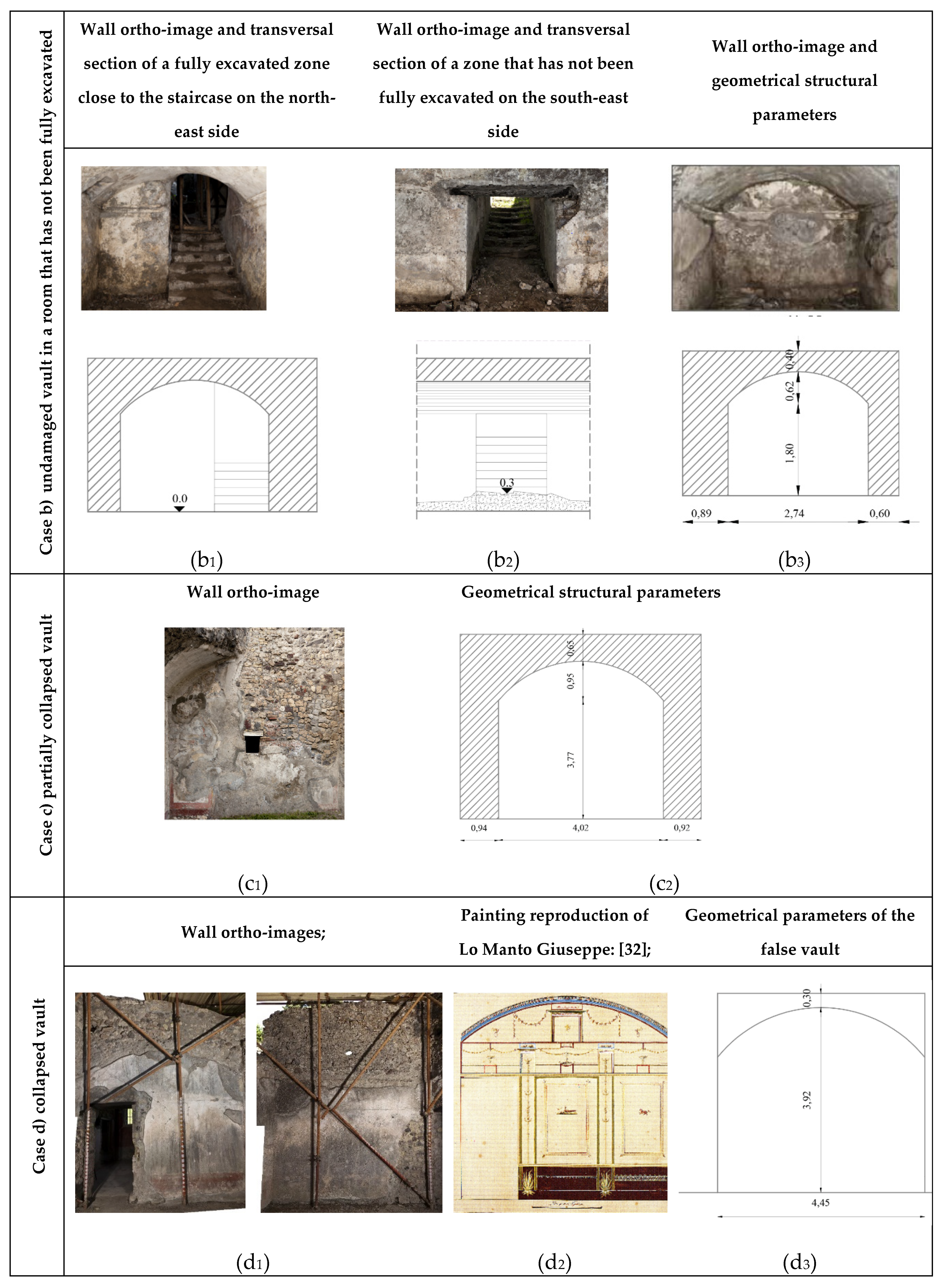
Figure 4.
(a) Archival source of Mazois, François (between 1809 and 1811): Section [34]; (b) archival source of La Vega, Francesco (between 1774 and 1775): Section (H. 48.0-L. 33.0 cm) [35]; (c) trace of holes (red box on the south wall of the peristyle) (photo: Thomas Crognier); (d) colonnade of the peristyle; and (e) reconstruction of the geometrical dimensions of the roof [dimensions in m].
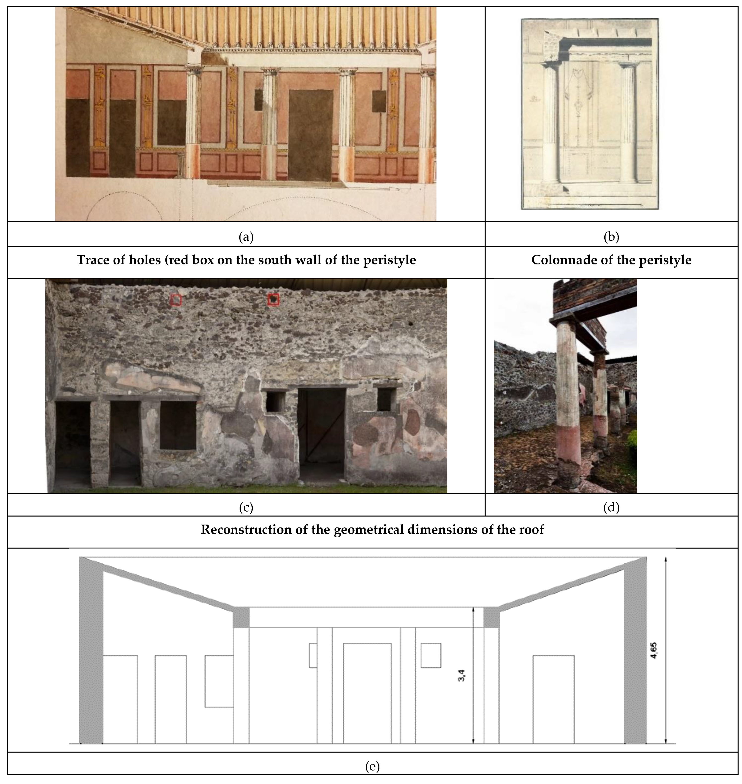
Figure 5.
Location of the masonry vaults and wooden floors at (a) ground level, (b) garden level and (c) cryptoporticus level in the Villa of Diomedes.
Figure 5.
Location of the masonry vaults and wooden floors at (a) ground level, (b) garden level and (c) cryptoporticus level in the Villa of Diomedes.
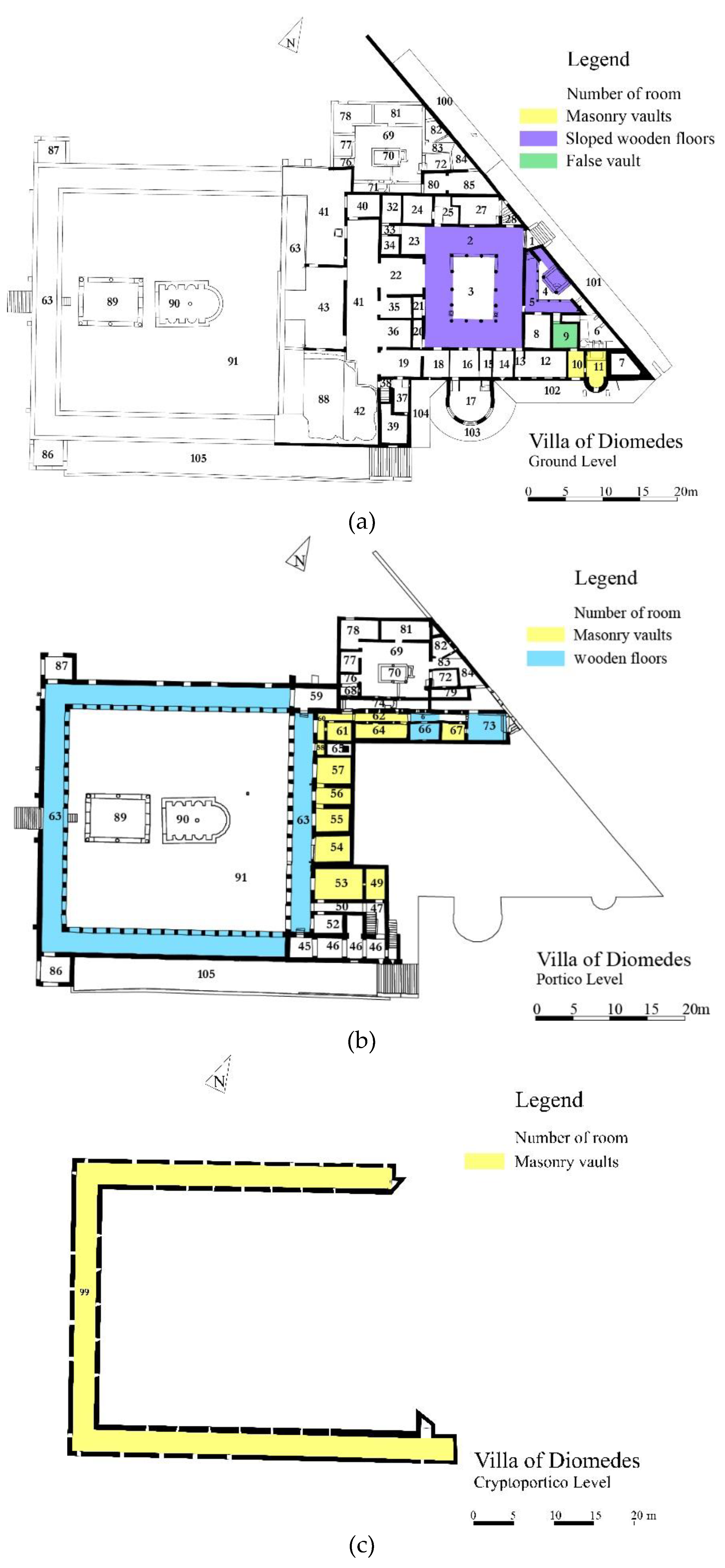
Figure 6.
Barrel vaults’ geometrical structural parameters.
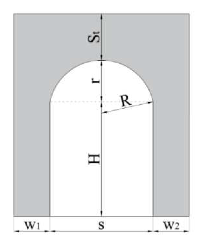
Figure 7.
Barrel vaults’ geometrical structural parameters [dimensions in m]: (a) rooms 10 and 11 at the ground level; (b) rooms 62-64; (d) room 67 and (e) rooms 53, 54, 55, 56, 57 and 60 at the garden level; (c) room 99 at the cryptoporticus level (photos: Thomas Crognier).
Figure 7.
Barrel vaults’ geometrical structural parameters [dimensions in m]: (a) rooms 10 and 11 at the ground level; (b) rooms 62-64; (d) room 67 and (e) rooms 53, 54, 55, 56, 57 and 60 at the garden level; (c) room 99 at the cryptoporticus level (photos: Thomas Crognier).
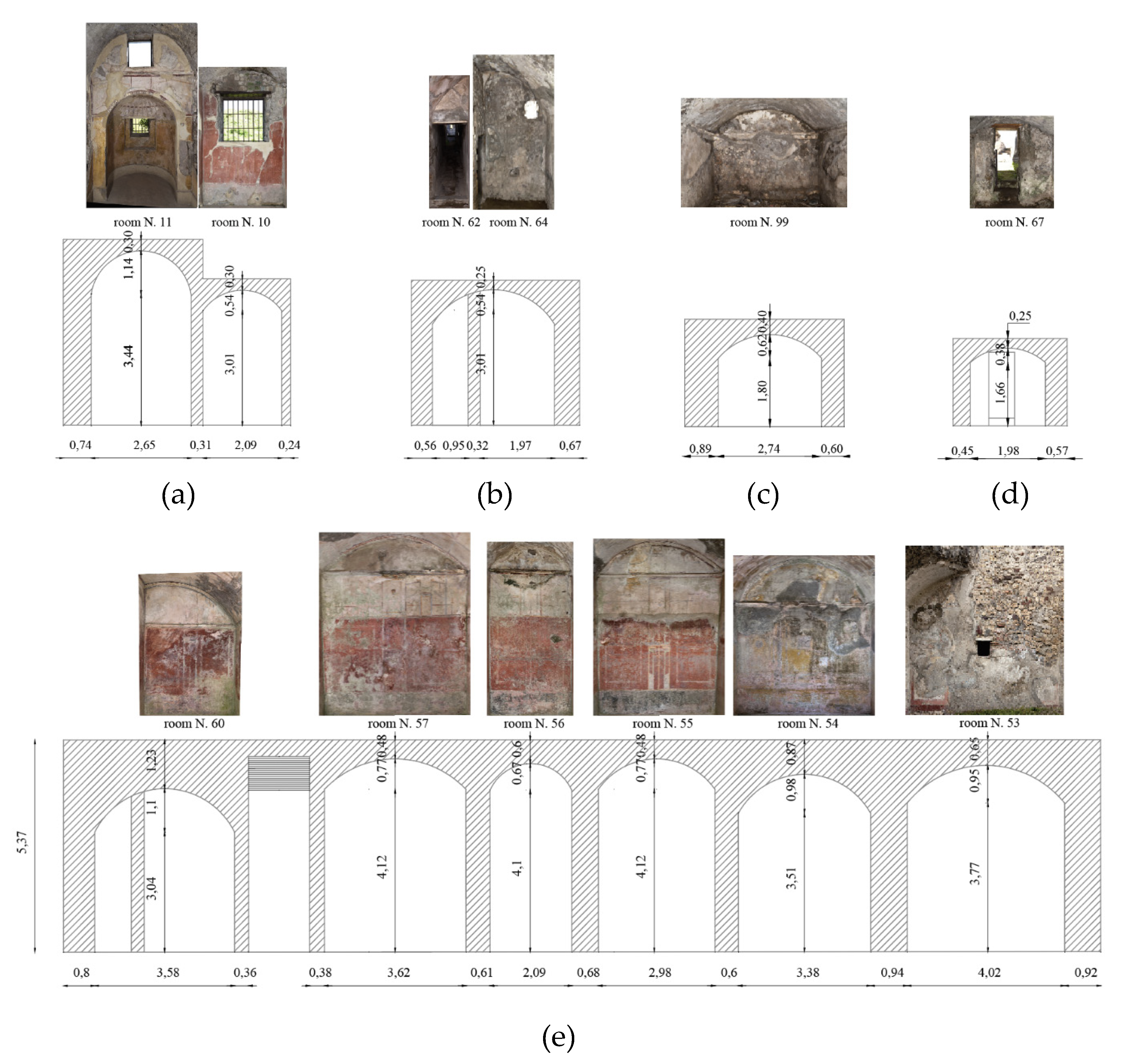
Figure 8.
(a) Barrel vaults’ geometrical parameters and relationships between the ratio r/s and (b) the thickness to span ratio, St/s; (c) thickness to rise ratio (St/r); (d) impost to pier width.
Figure 8.
(a) Barrel vaults’ geometrical parameters and relationships between the ratio r/s and (b) the thickness to span ratio, St/s; (c) thickness to rise ratio (St/r); (d) impost to pier width.
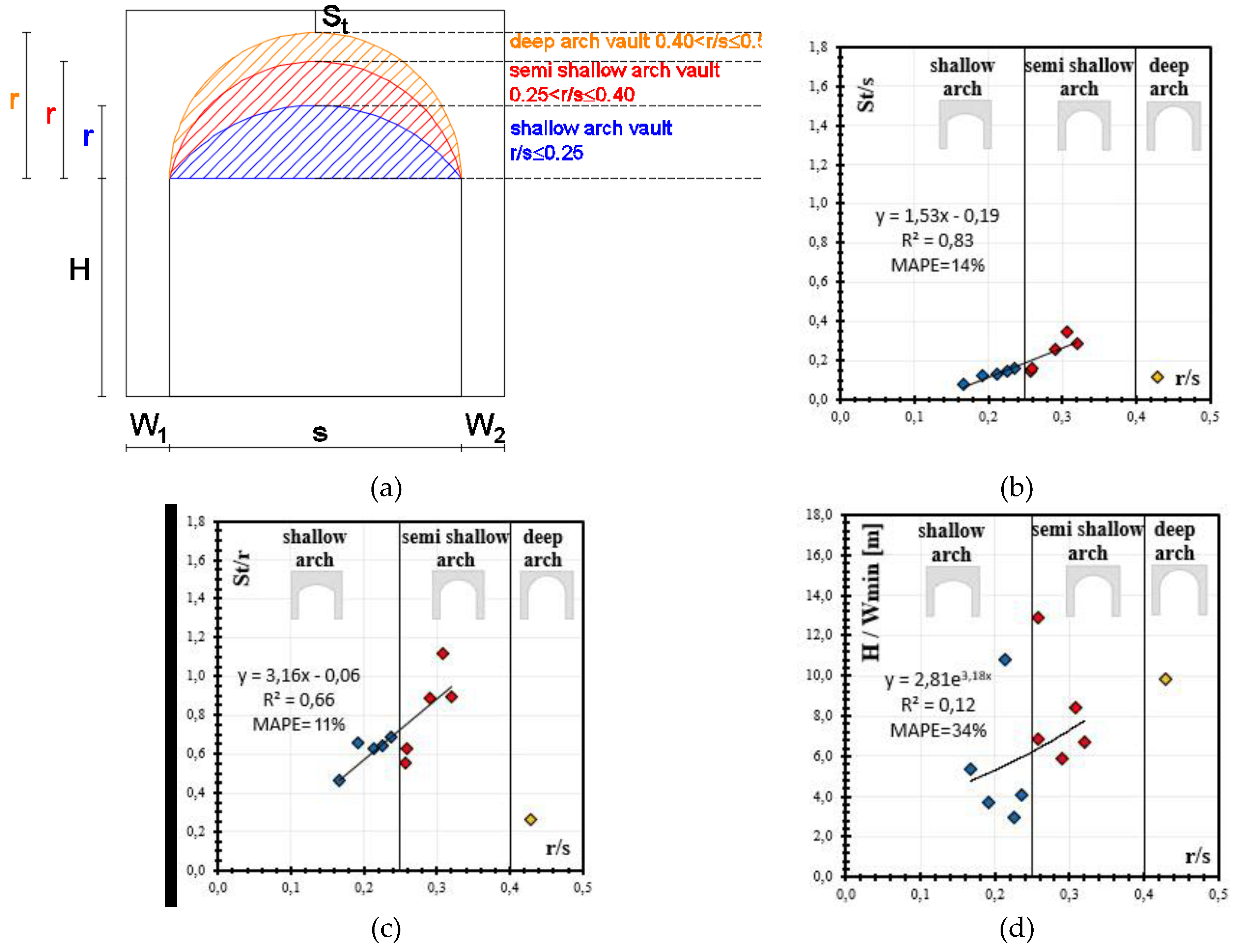
Figure 9.
Literature formulations for the design of (a) shallow arches and (b) deep arches; (c) formulations’ envelope and survey data.
Figure 9.
Literature formulations for the design of (a) shallow arches and (b) deep arches; (c) formulations’ envelope and survey data.
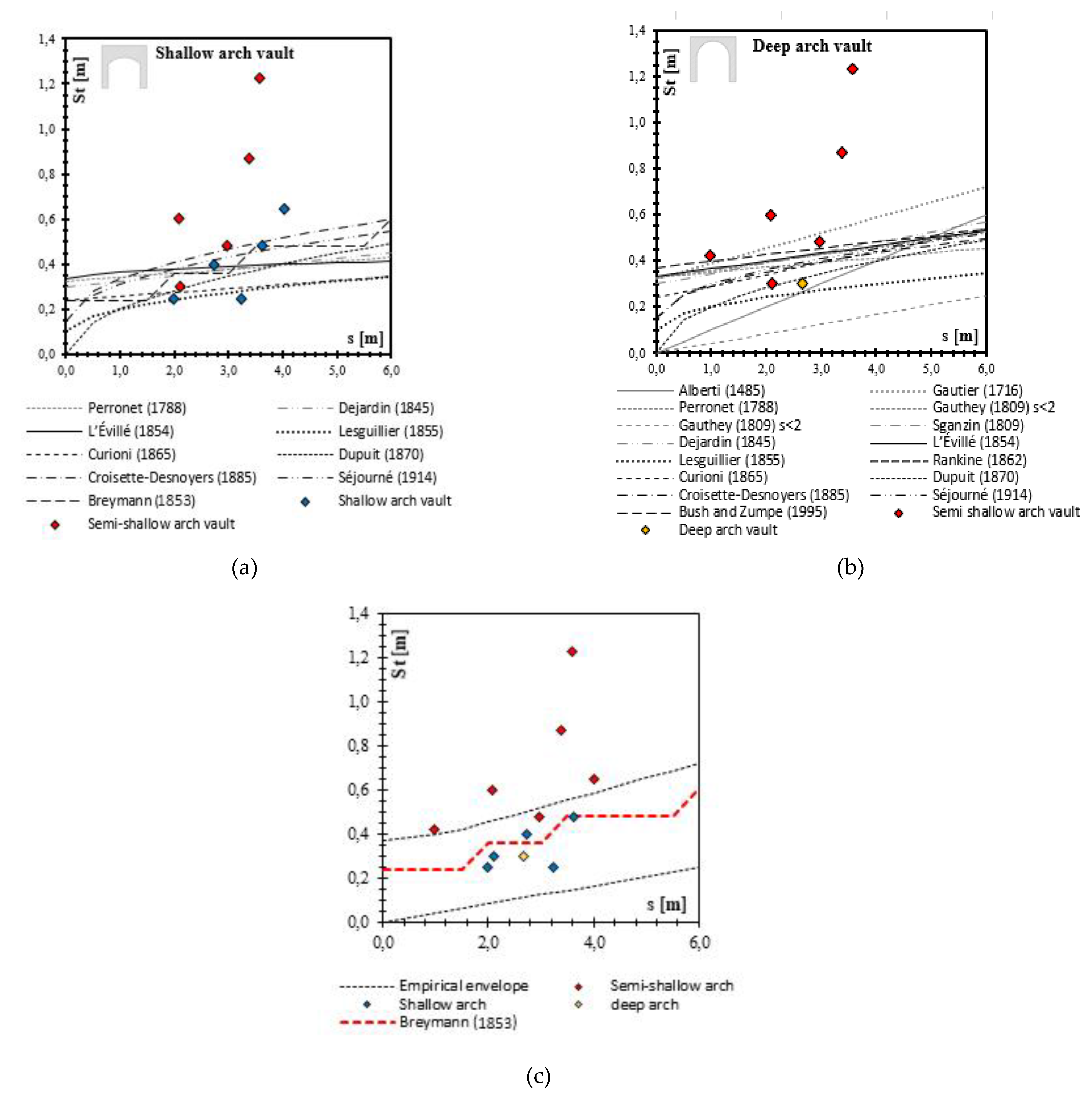
Figure 10.
Trace of wooden floor at the garden level in room 63: (a1) beam traces; (a2) conglomerate slab trace (highlighted in red); (a3) schematic floor-plan view and beam cross-section; in room 66: (b1) beam trace (photo: Thomas Crognier); (b2) schematic floor-plan view and beam cross-section; in room 73: (c1) beam traces on the south wall and (c2) east wall; (c3) schematic floor-plan view; (c4) cross-section of the north-south beams – Section A-A; (c5) cross-section of the east-west beams – Section B-B [dimensions in m] (photos: Thomas Crognier).
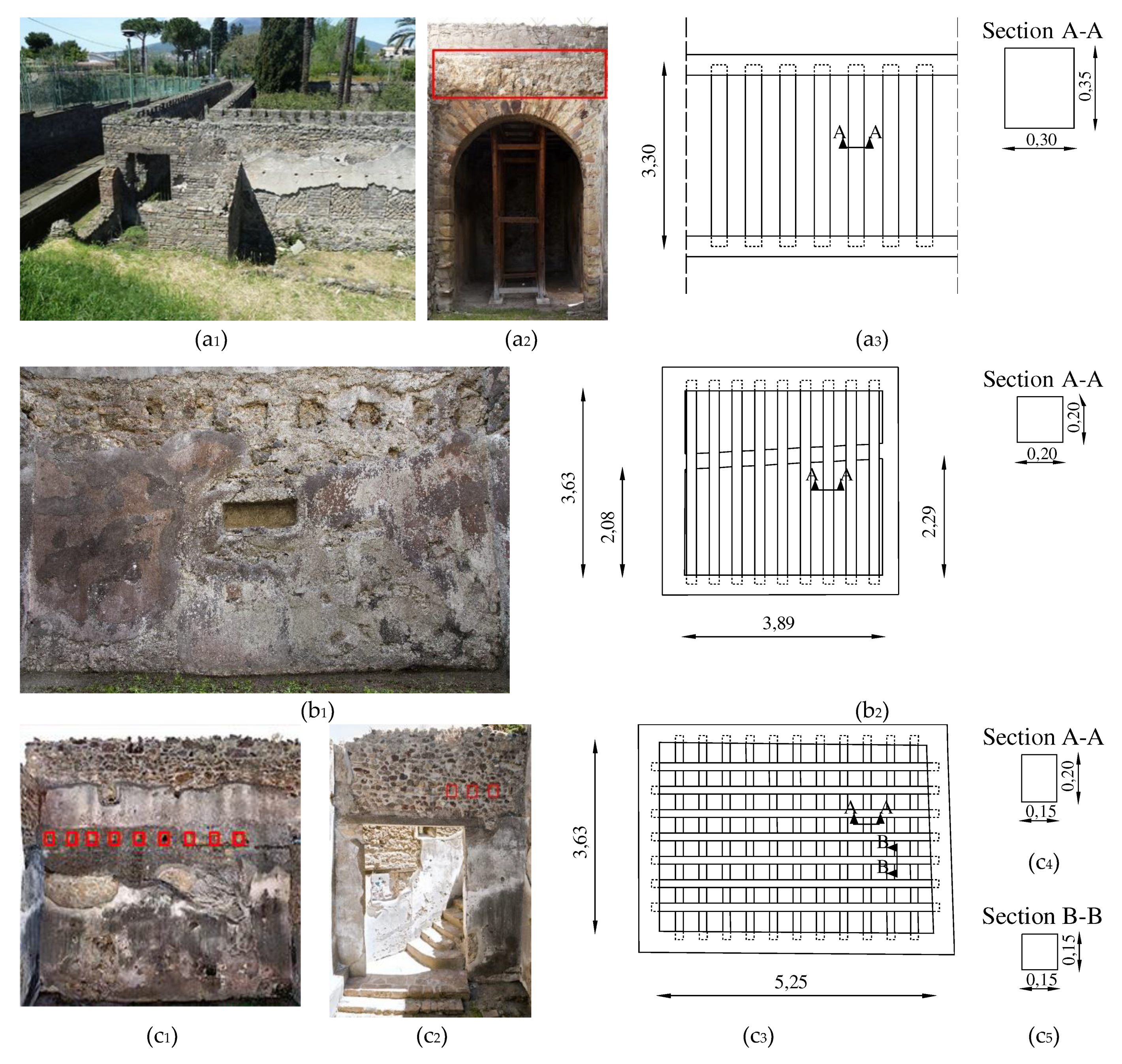
Figure 11.
Axonometric projection of the Villa of Diomedes:(a) plan; (b)overall view.
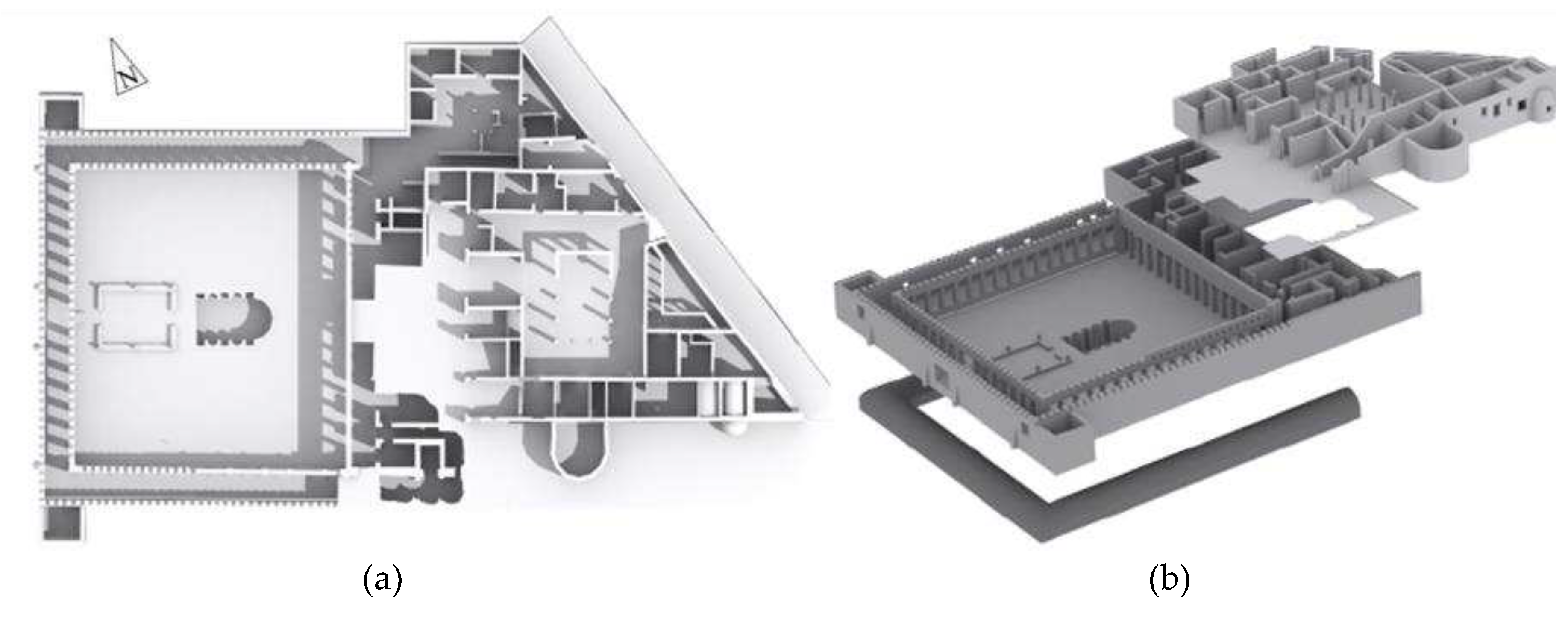
Figure 12.
Traces of beam holes (red box) and staircase (red line) (a) and relevant reconstruction (red) (b).
Figure 12.
Traces of beam holes (red box) and staircase (red line) (a) and relevant reconstruction (red) (b).
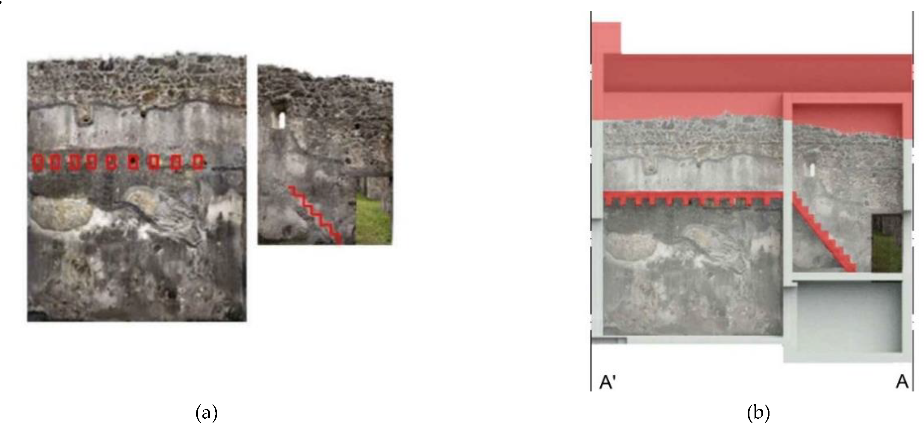
Figure 13.
3D model reconstruction at 79 A.D: (a)plan; (b) overall view.
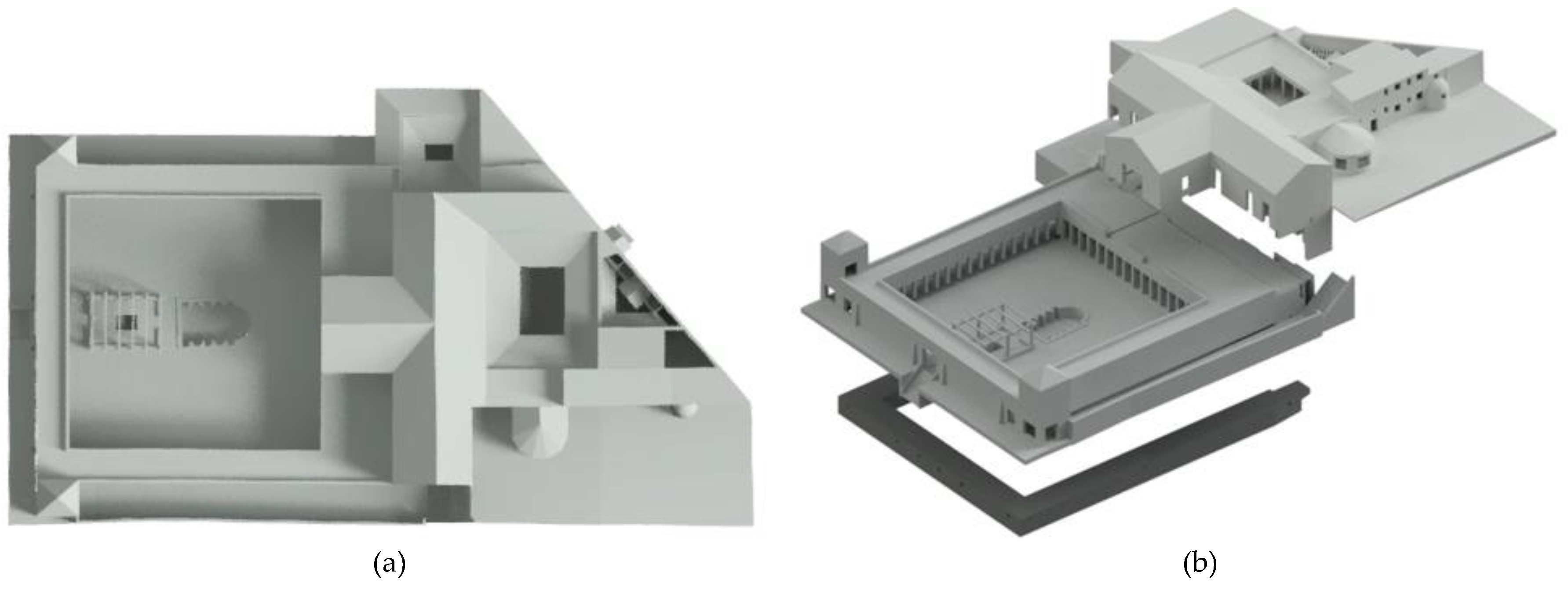

Table 1.
Barrel vaults’ geometrical structural parameters.
| Level | Room no. | Span, s[m] | Rise, r [m] |
r/s [-] |
Arch vault | Radius, R [m] |
Crown thickness, St [m] | Pier width, W1[m] | Pier width, W2[m] | Impost, H [m] |
|---|---|---|---|---|---|---|---|---|---|---|
| Ground level | 10 | 2.09 | 0.54 | 0.26 | semi-shallow | 1.20 | 0.30 | 0.23 | 0.33 | 3.01 |
| 11 | 2.65 | 1.14 | 0.43 | deep | 1.90 | 0.30 | 0.33 | 0.37 | 3.44 | |
| Garden level |
53 | 4.02 | 0.95 | 0.24 | shallow | 2.61 | 0.65 | 0.94 | 0.92 | 3.05 |
| 54 | 3.38 | 0.98 | 0.29 | semi-shallow | 1.95 | 0.87 | 0.60 | 0.94 | 2.85 | |
| 55 | 2.98 | 0.77 | 0.26 | semi-shallow | 1.83 | 0.48 | 0.68 | 0.60 | 3.33 | |
| 56 | 2.09 | 0.67 | 0.32 | semi-shallow | 1.15 | 0.60 | 0.61 | 0.68 | 3.32 | |
| 57 | 3.62 | 0.77 | 0.21 | shallow | 2.51 | 0.48 | 0.38 | 0.61 | 3.33 | |
| 60-61 | 3.58 | 1.1 | 0.32 | semi-shallow | 2.00 | 1.23 | 0.80 | 0.36 | 2.46 | |
| 62-64 | 3.24 | 0.54 | 0.17 | shallow | 1.94 | 0.25 | 0.56 | 0.67 | 3.01 | |
| 67 | 1.98 | 0.38 | 0.19 | shallow | 1.85 | 0.25 | 0.45 | 0.57 | 1.66 | |
| Cryptoporticus level | 99 | 2.74 | 0.62 | 0.23 | shallow | 1.37 | 0.40 | 0.89 | 0.6 | 1.8 |
Table 2.
Literature formulations for the design of shallow and deep-arch vaults.
| Shallow-arch vault r/s ≤0.25 | Deep-arch vault r/s>0.40 | References | ||
|---|---|---|---|---|
| Crown thickness, St | Pier width, W | Crown thickness, St | Pier width, W | |
| - | s/6≤W≤s/4 | St=s/10 | s/6≤W≤s/4 | Alberti (1485) [39] |
| - | - | St=0.32+s/15 | W= s/5 | Gautier (1717) [40,41,42,43] |
| St=0.325+0.0694R | - | St=0.325+0.0347s | W=2.25/s | Perronet (1788) [40,41,42,43] |
| - | - | St=0.33+s/48; s<2St=0.0416s; 2<s<16 | - | Gauthey (1809) [40,41,43] |
| - | - | St=0.325+0.034725 | - | Sganzin (1809) [42,43] |
| St=0.30+0.025S | - | St=0.30+0.045s | - | Dejardin (1845) [40,42,43] |
| - | - | St=0.24m; if s<1.75mSt=0.36m; if s[2m;3m]St=0.48m; if s[3.5m;5.75m]St=0.6 m; if s[6m;8.5m] | Breymann (1853) [42] | |
| St=0.333+0.033(s)0.5 | - | St=0.333+0.033s | L’Évillé (1854) [40,42,43] | |
| St=0.10+0.20(R)0.5 | - | St=0.10+0.20(R)0.5 | - | Lesguillier (1855) [40] |
| - | - | St=0.19(R)0.5 | - | Rankine (1862) [40,42,43] |
| St=0.24+0.07R (alfa<45°) | - | St=0.24+0.05s | Curioni (1865) [41] | |
| St=0.15(s)0.5 | - | St=0.20(s)0.5 | - | Dupuit (1870) [40,41,42,43] |
| St=0.15+0.183(s)0.5 | - | St=0.15+0.142(s)0.5 | - | Croisette-Desnoyers (1885) [42,43] |
| St=0.15+0.15µ(1+s)0.5 | s/10≤W≤s/8 | St=0.15+0.15(s)0.5 | s/10≤W≤s/8 | Séjourné (1913-1916) [42,43] |
| St=0.37+0.028s | Bush and Zumpe (1995) [42] | |||
Table 3.
Wooden floors’ structural parameters and stress ratios.
| Room no. | Type of wooden floor | Direction | Span, L [m] | Average beam spacing (center to center) [m] | Cross section [mxm] | N° of beams [-] | Thickness of floor [m] | Stress ratio fmax,DL/fm [-] |
Deflection ratio f/s [-] |
|---|---|---|---|---|---|---|---|---|---|
| 63 | one-way | - | 3.33 | 0.65 | 0.30x0.35 | n.a. | 0.68 | 2% - 3% | 1%-2% |
| 66 | one-way | - | 3.63 | 0.45 | 0.20x0.20 | 9 | 0.51 | 6%-10% | 5%-8% |
| 73 | two- way | north-south | 3.63 | 0.45 | 0.15x0.20 | 11 | 0.51 | 5%-8% 15%-26% |
13%-23% |
| east-west | 5.25 | 0.45 | 0.15x0.15 | 7 | 17%-30% |
Disclaimer/Publisher’s Note: The statements, opinions and data contained in all publications are solely those of the individual author(s) and contributor(s) and not of MDPI and/or the editor(s). MDPI and/or the editor(s) disclaim responsibility for any injury to people or property resulting from any ideas, methods, instructions or products referred to in the content. |
© 2023 by the authors. Licensee MDPI, Basel, Switzerland. This article is an open access article distributed under the terms and conditions of the Creative Commons Attribution (CC BY) license (http://creativecommons.org/licenses/by/4.0/).
Copyright: This open access article is published under a Creative Commons CC BY 4.0 license, which permit the free download, distribution, and reuse, provided that the author and preprint are cited in any reuse.


