

Submitted:
25 June 2023
Posted:
26 June 2023
You are already at the latest version
Abstract
Taking a certain type of test centrifuge as the research object, the finite element model of the test centrifuge is established, the vibration characteristics and aerodynamic performance of the test centrifuge are analyzed, and the structural optimization design of the test centrifuge is carried out. In this paper, the load is applied according to the actual working condition of a certain type of test centrifuge. The vibration of the mounting seat of the test centrifuge is analyzed and the structure of the mounting seat is optimized. After optimization, the vibration of the mounting seat is 77.38 % lower than that of the original mounting seat. Then, the aerodynamic analysis of the test centrifuge is carried out. The analysis results show that the test centrifuge moves more smoothly under the whole package shell and the steady flow shell, and the resistance decreases and the shaft load decreases. Finally, the steady flow shell of the test centrifuge is optimized. The analysis shows that the increase of the width of the steady flow shell can reduce the resistance coefficient, which is helpful to the stability of the test centrifuge during operation and reduces the unbalanced response of the system caused by air resistance.
Keywords:
Test centrifuge
; Numerical simulation
; Vibration analysis
; Pneumatic analysis
; Structural optimization design
1. Introduction
It is very important for equipment and people to be in a high-gravity environment in ultra-high altitude flight. At present, centrifuges are commonly used for scientific experiments to simulate high-gravity environment [1]. Centrifuges for scientific tests include geotechnical centrifuges [2], manned centrifuges [3] and precision test centrifuges. Centrifuges for scientific tests are a type of equipment that uses a high rotational speed rotating arm to generate centrifugal force more than several times that of gravity to simulate the high gravity environment to which equipment or people are subjected [4,5]. Precision test centrifuges are usually high-precision inertial navigation test equipment for inertial device verification, calibration and testing [6]. The precision test centrifuge equipment provides acceleration by rotating the central shaft. The greater the rotation radius, the greater the acceleration provided. Therefore, a pod is generally set at the end of the equipment to place various test equipment [7,8].
A lot of research has been carried out on precision test centrifuges at domestic and abroad. Ling et al.[9] established three types of acceleration measurement uncertainty evaluation models and calculated and verified the acceleration measurement uncertainty indexes that output by several precision test centrifuges. Wang et al.[10] carried out a study on the influence of structural errors of precision test centrifuges on the motion accuracy of the equipment itself and obtained the variation law between structural error parameters and equipment motion parameters. Cheng et al.[11] mainly studied the deformation of the turntable and the rotating arm during the operation of the precision test centrifuge. The results show that the increase of centrifugal load and temperature will lead to the increase of the deformation of the turntable and the rotating arm. Ren et al.[12]proposed a new method for the calibration of high-precision centrifuge accelerometers in order to further improve the calibration accuracy of the higher-order error model coefficients, and the calibration accuracy was greatly improved after applying the method. Liu et al.[13] studied the effect of temperature on the uncertainty of the static radius measurement of precision test centrifuge. Huang et al.[14] gave the calculation formula of the wind resistance power during the operation of the centrifuge, which provided a theoretical basis for the engineering design of the centrifuge.
In addition, the stability problem during the operation of the precision test centrifuge is very critical [15,16]. In this paper, the numerical simulation analysis of the vibration response and aerodynamic performance of the centrifuge structure is carried out for a certain type of test centrifuge. The external vibration response and the aerodynamic characteristics of the equipment flow field at the installation seat of the test centrifuge are analyzed emphatically. The equipment structure is optimized from two aspects of vibration and aerodynamics [17,18,19,20], which reduces the vibration response of the key components of the centrifuge rotation process and the aerodynamic resistance of the centrifuge, and improves the performance of the test centrifuge.
2. Numerical Model of Test Centrifuge
The test centrifuge studied in this paper is shown in Figure 1. The test centrifuge consists of a rotating arm, a rotating shaft, a pod and a counterweight area. The counterweight area can be trimmed by placing blocks of different weights to reduce the dynamic imbalance of the centrifuge [21]. The centrifuge is a whole rotary arm centrifuge, and the test piece in the pod is heavy. The force condition of the test centrifuge is shown in Figure 1. It can be seen that the centrifuge system is affected by two centrifugal forces in the opposite direction. When the two forces are balanced, the load of the shaft can be reduced. The three-dimensional model of the test centrifuge is established, and the vibration response of the centrifuge is analyzed by using the static simulation module. The static calculation model of the test centrifuge is shown in Figure 2.
3. Vibration Numerical Simulation and Structural Optimization Design of Test Centrifuge
3.1. Vibration of Test Centrifuge
During the operation of the test centrifuge, the vibration at the mounting seat comes from the unbalance of the whole machine, the external vibration at the pod and the vibration at the bearing. In order to ensure the safe and stable of centrifuge, it is necessary to control the vibration at the mounting seat within the safety line.
There are many reasons for the imbalance of equipment in rotating machinery. The imbalance will make the rotating shaft bear excessive bending and torsion, which will lead to instability. In order to solve the above problems, it is necessary to identify and eliminate the imbalance of equipment [22,23,24]. The first load is G40 dynamic unbalance.
In the equation, M is the rotating arm mass, G is the unbalanced precision grade, r is the correction radius, n is the working rotating speed of the centrifuge, and m is the unbalanced qualified quantity. The dynamic unbalance is simulated by applying force on the counterweight end face. According to Equation 1 [25], the dynamic unbalance G is 40, the centrifuge speed is 38r/min. It is calculated that the counterweight end should apply 200 kg weight. According to Equation 2, it is calculated that a force of 19,077 N should be applied along the Y-axis direction at the counterweight end, as shown in Figure 3a. According to the spindle speed of 38r/min, the harmonic response analysis frequency is 0~0.6333Hz. The second load is the external vibration of the test piece in the pod, and its value is 1g.
The acceleration excitation is converted into force by Equation 3. According to the mass of the test piece in the external vibration pod, and the calculated excitation size is 7840N. Therefore, the force is applied in all directions of the test piece, as shown in Figure 3b. According to the test piece speed in 2400-17000r/min, the harmonic response analysis frequency is 40~290Hz.
The last one is bearing vibration. The excessive clearance of the bearing itself and the interaction between the bearings in the rotating machinery will cause excessive vibration response of the equipment. To solve the problems, the appropriate bearing should be selected in the design [26,27,28]. In order to simulate the vibration excitation of the bearing, the excitation force generated by the residual unbalanced mass is applied at the upper and lower spindle bearings, that is, the force of 19,077 N along the angular bisector of the X and Y axes, as shown in Figure 3c. The bearing characteristic frequencies of radial bearing and thrust bearing are calculated respectively, including the frequency fbpfi of the rolling element passing through the inner ring, the rotation frequency fbsf of the rolling element, and selecting the maximum value as the harmonic response analysis frequency to simulate the bearing excitation. According to equation 4, equation 5 and equation 6, the frequency of the rolling part passing through the inner ring and the rotation frequency of the rolling part are calculated respectively.
In this equation, D is the bearing pitch diameter, Di is the bearing inner ring raceway diameter, Do is the bearing outer ring raceway diameter, d is the rolling element diameter, α is the rolling element contact angle, Z is the number of rollers, fi is the rotation frequency of the inner ring around the center of the circle. Radial bearing parameters and thrust bearing parameters are shown in Table 2. The frequency of the rolling element of the radial bearing through the inner ring is calculated to be 11.57Hz by Equation 5, and the frequency of the rolling element of the radial bearing through the inner ring is calculated to be 12.74Hz. The rolling element rotation frequency of the radial bearing is calculated to be 4.16Hz by Equation 6, and the rolling element rotation frequency of the radial bearing is calculated to be 5.33Hz.

Table 1.
Bearing parameter.
| Parameter | Radial bearing | Thrust bearing |
|---|---|---|
| D/mm | 685 | 800 |
| Di/mm | 770 | 1060 |
| Do/mm | 727.5 | 930 |
| d/mm | 55 | 55 |
| α/° | 0 | 40 |
| Z | 34 | 38 |
| fi/Hz | 0.633 | 0.633 |
3.2. Harmonic Response Analysis Results
The rotational speed of the test centrifuge was 38r/min. Three excitations of unbalance, external vibration and bearing vibration were applied in the harmonic response analysis. The vibration response of the support seat was linearly superimposed to analyze the maximum vibration response of the support seat. The static analysis adopts harmonic response analysis. The constraint setting in the analysis corresponds to the actual situation. A total of 1 fixed constraint, 9 spring connections and 8 bearing connections are applied. Radial bearing stiffness K1 and thrust bearing stiffness K2 are calculated according to Equation 7 [29].
In this equation, K is the bearing stiffness, Z is the number of rollers, β is the contact angle of the roller, l is the effective length of the roller, d3 is the diameter of the roller, and R is the radial load.
The first one is vibration response under unbalanced excitation. According to the spindle rotating speed, 0~0.6333Hz is set to simulate the harmonic response analysis frequency of G40 dynamic unbalance. The force is 19077N along the Y axis. As shown in Figure 4a, the maximum vibration velocity response of the mounting seat under unbalanced excitation is 0.023mm/s. The second one is vibration response of test piece in pod under external vibration excitation. According to the rotational speed of the test piece, the harmonic response analysis frequency of the external vibration is set to 40~290Hz. The force applied to the bottom of the test piece is 7840 N along the vertical direction, the radial direction of the centrifuge and the tangential negative direction of the centrifuge. As shown in Figure 4b, the maximum vibration velocity response of the mounting seat is 2.4998mm/s under the external vibration excitation. The last one is vibration response of bearing under vibration. The harmonic response analysis frequency is 0~22Hz to simulate the harmonic response analysis frequency of bearing vibration. The force is set to 13,500 N along the X and Y axes. As shown in Figure 4c, the maximum vibration velocity response of the mounting seat under bearing vibration excitation is 5.2242mm/s.
According to the analysis results, the maximum vibration velocity response of the mounting seat is 7.747mm/s under the combined action of external vibration excitation, unbalanced excitation and bearing vibration excitation. The specific data are shown in Table 2.
3.3. Optimization Design of Mounting Seat
In order to reduce the vibration response of the experimental centrifuge mounting seat, the mounting seat model is optimized. The optimized model applies annular stiffeners at the top of the mounting seat and extends the original stiffeners. The wall thickness of the mounting seat is increased from 26 mm to 30 mm, as shown in Figure 5. The modified model is simulated again and compared with the original model.
The load and constraint application are consistent with the model of the mounting seat before optimization. According to the analysis results, the maximum vibration velocity response of the optimized mounting seat under the combined action of external vibration excitation, unbalanced excitation and bearing vibration excitation is 1.754mm/s, which is 77.36% lower than that before optimization. The specific data are shown in Figure 6, Table 3.
4. Aerodynamic Numerical Simulation and Structural Optimization Design of Test Centrifuge
In order to improve the stability of the test centrifuge during operation, considering the aerodynamic performance of the whole machine, the structure is optimized according to the aerodynamic numerical simulation results. The numerical model of the test centrifuge was imported into the ANSYS SCDM module to establish the flow field calculation model, and the flow field analysis was carried out based on the Fluent flow field calculation module. The operation and environmental parameters of the test centrifuge are shown in Table 4. The rotation direction of the test centrifuge is clockwise, and its flow field calculation model are shown in Figure 7.
4.1. Aerodynamic Numerical Simulation Method
The numerical simulation of the flow field uses the relative reference frame method to simulate the movement of the test centrifuge system. The wall of the test centrifuge is set to be static, the internal flow field is set to rotate around the central axis, and the speed is 38rpm. The external flow field is relatively static, the external flow field contains the central axis wall, and the absolute motion of the central axis wall is set, and the speed is 38rpm. As shown in Figure 8.
When the air is the flowing medium, the drag(lift) of the object moving in the air can be calculated by Equation 8. In the equation, Y is the drag(lift) of the object or system moving in the air, ρ is the density of the flow medium at a specific temperature. The flow medium analyzed in this paper is the air with a density of 1.169kg/m3 at 25℃, C is the drag coefficient, S is the windward area, and v is the flow velocity of the medium. According to Equation 8, the drag coefficient(lift coefficient) calculation Equation 9 is obtained.
4.2. The Influence of the Whole Package Shell of the Test Centrifuge on the Aerodynamic Resistance
The finite element aerodynamic analysis of the flow field model of the test centrifuge shown in Figure 1 is carried out, and the vortex core distribution diagram obtained by the analysis is derived. The vortex core is a dense area of internal vortices. The vortex will produce vortex vibration, as will the vortex core. Vortex vibration is an important factor affecting the vibration of the rotating platform of the test centrifuge [30]. From the vortex core area map, it can be seen that the vortices at the rotating shaft and the pod are dense, as shown in Figure 9a. In order to analyze the influence of the whole package shell on the aerodynamic drag, all the openings of the model are filled in, that is, the influence of the whole package shell on the surrounding flow field is simulated in the test centrifuge. The test centrifuge model after adding the whole package shell is shown in Figure 10a. The aerodynamic analysis of the test centrifuge model after adding the whole package shell is carried out, and the vortex core distribution map obtained by the analysis is derived. It is found that the overall vortex core quantity is reduced after the structure is changed, indicating that the whole package shell structure suppresses the occurrence of vortex vibration, as shown in Figure 9b.
Through the analysis, it is concluded that the amount of vortex core is less in the state of the whole package shell, and the decrease of the amount of vortex core means the decrease of the amount of vortex. During the operation process of the test centrifuge, the vortex shedding near the vortex will lead to vortex vibration. The generation of vortex vibration will cause the test centrifuge to be excited by pulsation, resulting in unstable motion and greater resistance during rotation. Therefore, the motion of the test centrifuge with the whole package is more stable and the resistance is smaller than that without the whole package. Then, the structural improvement of the whole package shell for the test centrifuge model is proposed.
4.3. The Influence of Steady Flow Shell on the Aerodynamic Performance of Centrifuge
The test centrifuge model adds a whole package of casing, and the test centrifuge model is shown in Figure 10a. After the whole package shell is added to the test centrifuge, its stability is improved, but the resistance of the centrifuge system is very large, especially on the windward side. Therefore, on the basis of the original structure, a steady flow shell is added, as shown in Figure 10b. After increasing the steady flow shell, the impact of air on the centrifuge itself can be reduced, so that the air flow can smoothly cross the centrifuge. Due to the existence of the steady flow shell on the leeward side, the phenomenon of vortex shedding also decreases to a certain extent. The flow field model of the test centrifuge after adding the steady flow shell is established, and the relevant parameters in the flow field remain unchanged.
The flow field analysis of the above two test centrifuge models is carried out respectively, and the average flow velocity, drag coefficient and lift coefficient of the two cases are obtained by CFD post-processing software. The relevant data are shown in Table 5, Table 6, Table 7 and Table 8.
The drag and lift, drag coefficient and lift coefficient were obtained under two conditions with and without steady flow shell. The above analysis shows that the resistance of the test centrifuge with steady flow shell is smaller than that without steady flow shell, and the decrease is 22.0%. The resistance coefficient with steady flow shell is 24.6% lower than that without steady flow shell. The lift coefficient with steady flow shell is 64.7% lower than that without steady flow shell, and the lift with steady flow shell is 52.7% lower than that without steady flow shell.
4.4. Optimization Design of Steady Flow Shell
The stability of the test centrifuge during rotation is particularly important. As mentioned above, the test centrifuge with a steady flow shell has good aerodynamic performance, and the resistance and resistance coefficient are reduced. In order to further improve the stability of the test centrifuge during operation and explore the influence of the streamline of the steady flow shell on the test centrifuge, five different streamline models of the steady flow shell were established to optimize the steady flow shell of the test centrifuge model. The streamline improvement position of the steady flow shell is mainly in the front wing and the rear wing, as shown in Figure 10b.
The change of streamline is mainly to change the width H of the steady flow shell extending to the side, as shown in Figure 10b. The side extension width of the front wing and the rear wing is adjusted, and the design width is 250mm, 350mm, 500mm, 700m, 950mm. The aerodynamic analysis of five steady flow shell models is carried out respectively. The drag coefficient is shown in Figure 11 and Table 9.
The analysis results show that the higher the extension width of the front and rear wings, the lower the drag coefficient, and the maximum decrease is 11.4%. The aerodynamic performance of the test centrifuge is improved and the stability of the equipment during operation is guaranteed.
5. Conclusions
In this paper, the vibration and aerodynamic performance of a certain type of test centrifuge is studied. The vibration and aerodynamic numerical simulation of centrifuges with different structures is carried out. The changes of vibration and aerodynamic performance of test centrifuges before and after optimization are analyzed. The main conclusions are as follows:
The strengthened mounting seat can effectively reduce the vibration response of the equipment. The overall vibration response of the equipment is reduced from 7.747 mm/s to 1.754 mm/s, with a decrease of 77.36%.
The whole package shell can effectively improve the stability of the test centrifuge system during operation. The steady flow shell can significantly reduce the resistance and lift of the test centrifuge during operation. The resistance decreases by 22.0%, the resistance coefficient decreases by 24.6%, the lift decreases by 64.7%, and the lift coefficient decreases by 52.7%.
For a certain type of test centrifuge, the application of strengthened mounting seat and steady flow shell structure can improve the stability of the equipment during operation. At the same time, the optimization design in this paper can improve the design efficiency of test centrifuge equipment.
Author Contributions
Conceptualization, D.-C.Y.; writing—original draft preparation, D.-C.Y. and L.-D.H.; writing—review and editing, D.-C.Y., L.-D.H., Z.-F.T., and X.-Y.J.; supervision, L.-D.H.; All authors have read and agreed to the published version of the manuscript.
Funding
The authors wish to thank the support of the National Science and Technology Major Project (2017-IV-0010-0047), the China Postdoctoral Science Foundation funded project (2020M670113) and the Beijing Natural Science Foundation (3224066) and the Fundamental Research Funds for the Central Universities (JD2324).
Data Availability Statement
No new data were created.
Conflicts of Interest
The authors declare no conflict of interest.
References
- Shen, W.B.; Hong, J.Z.; Min, L.W. Development on Large Scale High-Dynamic Centrifuge for Aviation Equipment. Measurement & Control Technology 2015, 34, pp. 85-88.
- Seong, J-T.; Kim, D. Seismic evaluation of offshore wind turbine by geotechnical centrifuge test. Wind Energy 2019, 22, pp. 1034– 1042.
- Mohajer, N.; Najdovski, Z.; Nahavandi, S. Design and development of a low-cost high-g centrifuge system(cyclone). International Conference on Control, Mechatronics and Automation 2019, pp. 305-309.
- Li, Q.S.; Xu, Y.H.; Luo, L. Review on Development of Centrifuge for Scientific Tests. Equipment Environmental Engineering 2015, 12, pp. 1-10.
- Centrifuge for scientific tests. Defence Science & Technology Industry 2015, 7, pp. 51.
- Yang, M.; Tang, L.; Zhang, C.J. The status and future of precision centrifuge. Navigation Positioning and Timing 2016, 3, pp. 17-21.
- Yao, Y.J.; Si, G.C. The present situation and development trend of contemporary manned centrifuges. Medical Journal of Air Force 2012, 28, pp. 60.
- Navid, M.; Darius, N.; Matthew, W.; Saeid, N. Motion and dynamic analyses of a human centrifuge system with an efficient design configuration. Aerospace Science and Technology 2021, 117, pp. 10-69.
- Ling, M.X.; Li, Q.S.; Li, H.M. Uncertainty evaluation model of acceleration measurement for precision centrifuge. Equipment Environmental Engineering 2015, 12, pp. 125-130.
- Wang, H.B.; Zhang, Y.M.; Li, F. Influence of structure error on the rotary precision of precision centrifuge. Equipment Environmental Engineering 2015, 12, pp. 72-77.
- Cheng, Y.B.; Lu, Y.G.; Zhang, Y.M. Variation of precise centrifuge plate/arm. Equipment Environmental Engineering 2015, 12, pp. 88-94.
- Ren, S.; Liu, Q.; Zeng, M.; Wang, C. Calibration Method of Accelerometer’s High-Order Error Model Coefficients on Precision Centrifuge. Transactions on Instrumentation and Measurement 2020, 69, pp. 2277-2286.
- Liu, S.H.; Chen, W.Y.; Fu, X. Temperature characteristics of uncertainty of static radius measurement of precision centrifuge. Equipment Environmental Engineering 2022, 19, pp. 115-120.
- Huang, P.; Yin, Y.H.; Li, S.L. Analysis of wind resistance power and starting process of centrifuge. Equipment Environmental Engineering 2015, 12, pp. 105-120.
- Huo, X.; Zheng, S.; Yao, Y. A Practical Strategy of Unbalance Identification and Correction for 2-DOF Precision Centrifuges. Journal of Harbin Institute of Technology 2018, 25, pp. 29-38.
- Ma, X.F.; Liu, P.N.; Yang, X.M. Aerodynamic performance analysis and structure optimization of a large industrial steam turbine exhaust hood. Measurement & Control Technology 2015, 34, pp. 85-88.
- Wang, Y.C.; He, G.Y.; Wang, Q. Aerodynamic performance analysis and optimization of tilt-wing UAV in return transition section. Science Technology and Engineering 2022, 22, pp. 9848-9856.
- Yang, X. Discussion on three-dimensional aerodynamic analysis method of turbine blade. Dual Use Technologies & Products 2018, 12, pp. 174.
- Hou, J.C.; Zhou, W.; Zhu, X.F. Aerodynamic analysis of fixed wing profile of small aircraft based on fluent. Electronic Test 2019, 12, pp. 43-44.
- Li, X.Y.; Yang, Y.S.; Hong, J.Z. Design of equilibrium regulation system for human centrifuge. Journal of Machine Design 2012, 29, pp. 71-74.
- Ali, M.; Isooda, K. Optimal motion cueing algorithm for accelerating phase of manned spacecraft in human centrifuge. Chinese Journal of Aeronautics 2020, 33, pp. 1991-2001.
- Diouf, P.; Herbert, W. Understanding rotor balance for electric motors. Conference Record of Annual Pulp and Paper Industry Technical Conference 2014, pp. 7-17.
- Ahobal, N.; Prasad, SLA. Study of vibration characteristics of unbalanced overhanging rotor. International Conference on Advances in Materials and Manufacturing Applications 2019, 577.
- Abbasi, A.; Firouzi, B.; Sendur, P. et al. Identification of unbalance characteristics of rotating machinery using a novel optimization-based methodology. Soft Computing 2022, 26, pp. 4831-4862.
- Wen, C.B. Residual unbalance analysis of high-speed drive shaft. Auto Time 2019, 34, pp. 141-142.
- Daniel, R.V.; Siddhappa, S.A.; Gajanan, S.B.; Philip, S.V.; Paul, P.S. Effect of bearings on vibration in rotating machinery. International Conference on Materials, Alloys and Experimental Mechanics 2017, 225.
- Kostek, R. Simulation and Analysis of Vibration of Rolling Bearing. Key Engineering Materials 2013, 588, pp. 257-265.
- Liu, Y.F.; Yan, C.F.; Kang, J.X.; Wang, Z.G.; Wu,L.X. Investigation on characteristics of vibration interaction between supporting bearings in rotor-bearing system. Measurement 2023, 216.
- Wang, G.; Guo, M.L. Stiffness of aerospace rolling bearings. Journal of Harbin Institute of Technology 2001, 33, pp. 644-645.
- Prantik, D.; Nagar, P.; Sagar, K.; Rushikesh, R.; Gokul, R. Aerodynamic analysis of bionic winglet-slotted wings. Materials Today 2022, 62, pp. 6701-6707.
Figure 1.
The structure and motion trajectory of the test centrifuge.
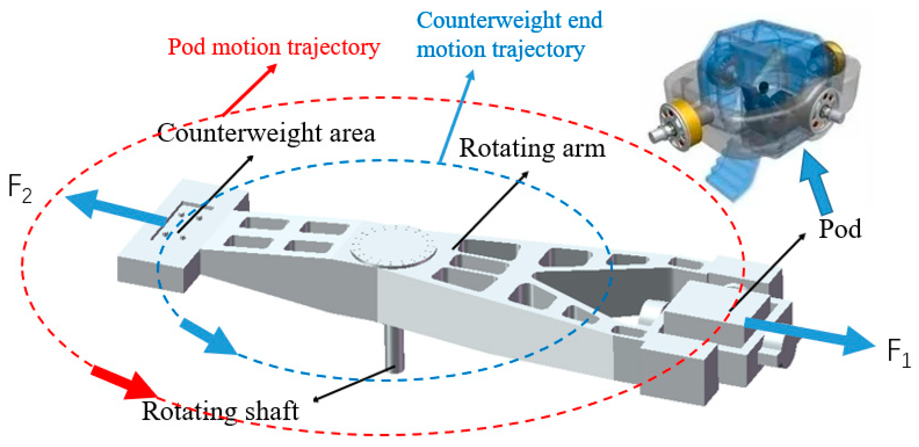
Figure 2.
Statics calculation model of test centrifuge.
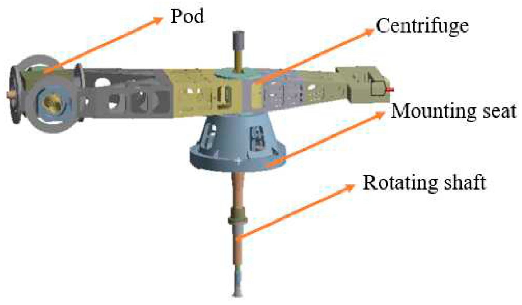
Figure 3.
Vibration analysis results: (a) Unbalanced excitation load; (b) External vibration load; (c) Vibration load of bearing.
Figure 3.
Vibration analysis results: (a) Unbalanced excitation load; (b) External vibration load; (c) Vibration load of bearing.
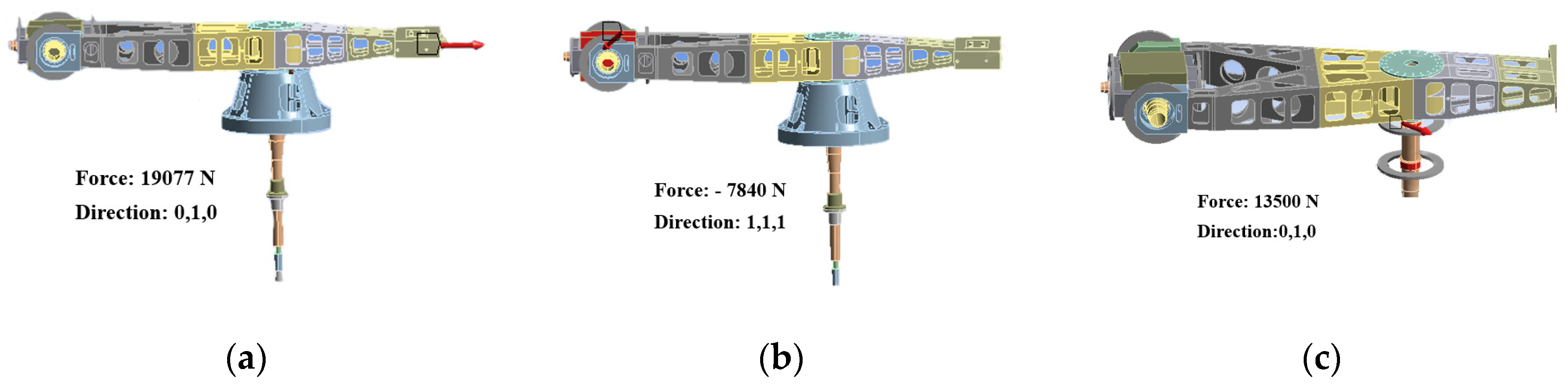
Figure 4.
Vibration analysis results: (a) Vibration velocity response of the mounting seat under unbalanced excitation; (b) Vibration velocity response of mounting base under external vibration excitation; (c) Vibration velocity response of mounting seat under bearing vibration excitation.
Figure 4.
Vibration analysis results: (a) Vibration velocity response of the mounting seat under unbalanced excitation; (b) Vibration velocity response of mounting base under external vibration excitation; (c) Vibration velocity response of mounting seat under bearing vibration excitation.
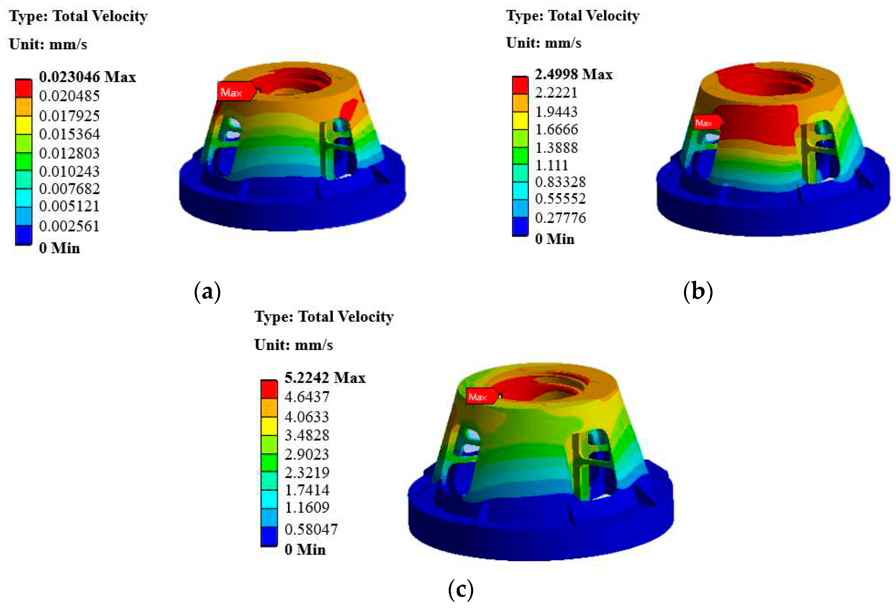
Figure 5.
Optimized mounting seat.
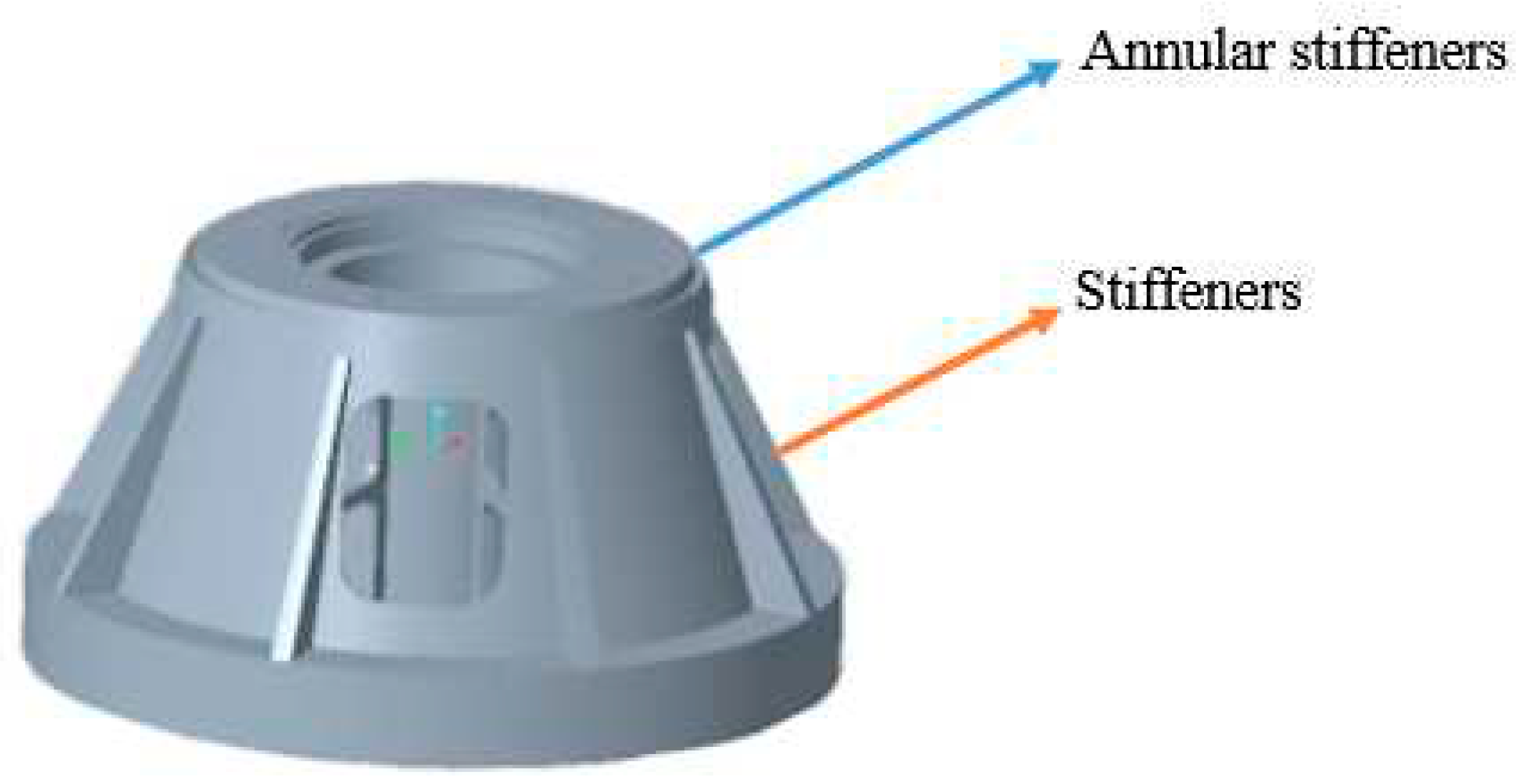
Figure 6.
The optimized vibration analysis results: (a) Vibration velocity response of the mounting seat under unbalanced excitation; (b) Vibration velocity response of mounting base under external vibration excitation; (c) Vibration velocity response of mounting seat under bearing vibration excitation.
Figure 6.
The optimized vibration analysis results: (a) Vibration velocity response of the mounting seat under unbalanced excitation; (b) Vibration velocity response of mounting base under external vibration excitation; (c) Vibration velocity response of mounting seat under bearing vibration excitation.
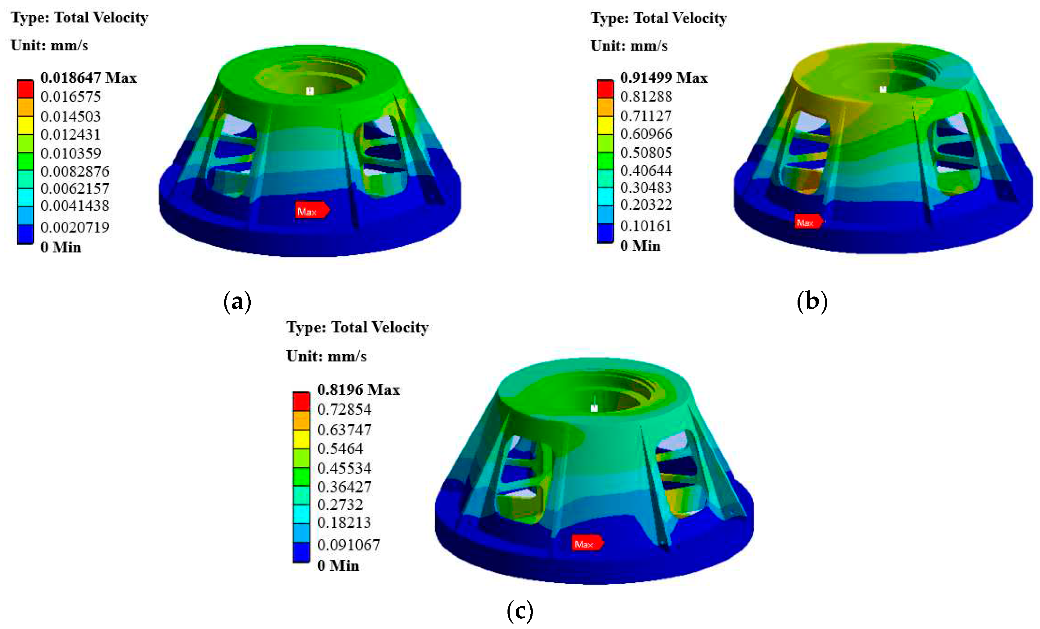
Figure 7.
Flow field calculation model of test centrifuge.
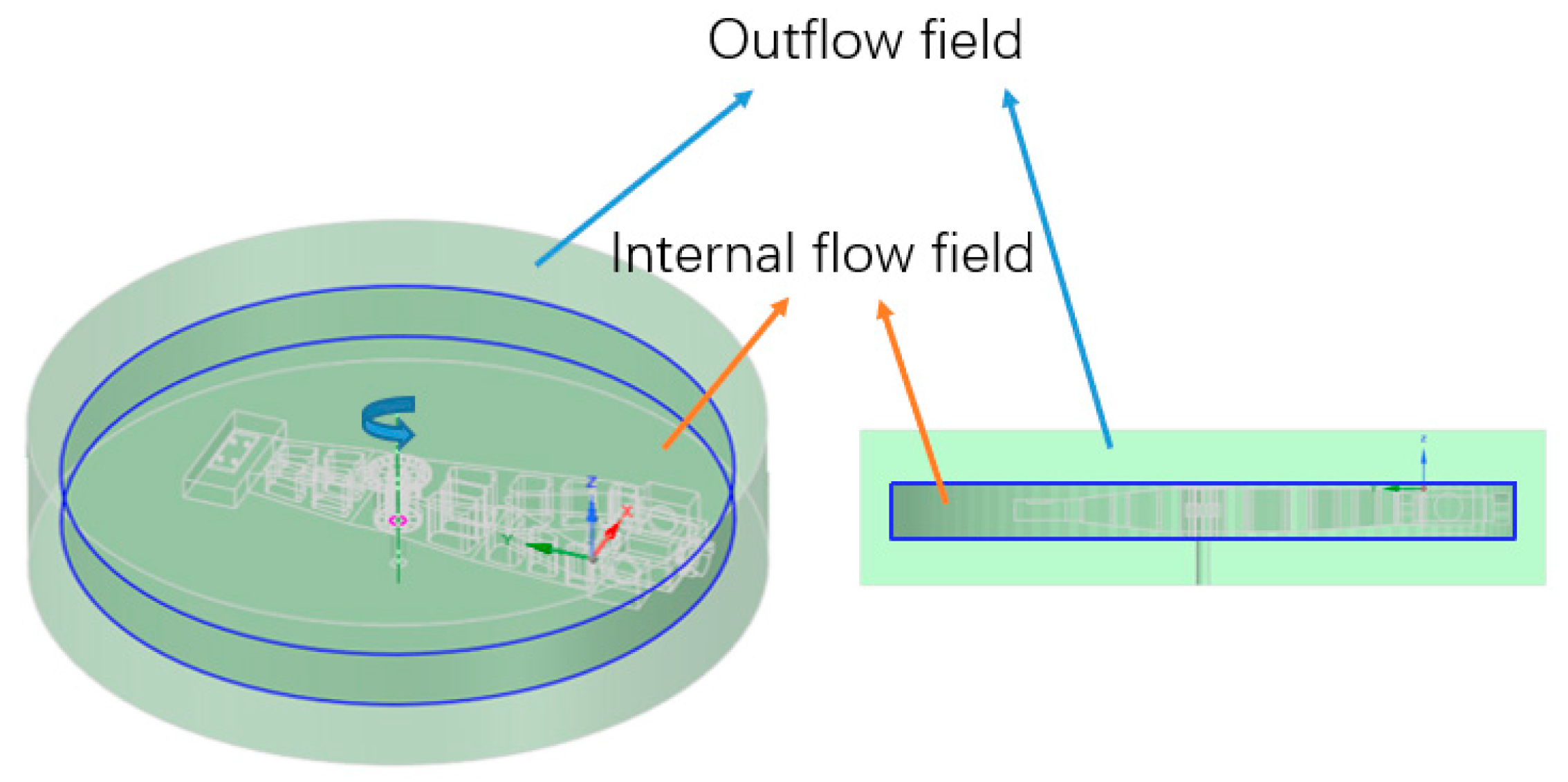
Figure 8.
Boundary conditions schematic diagram.
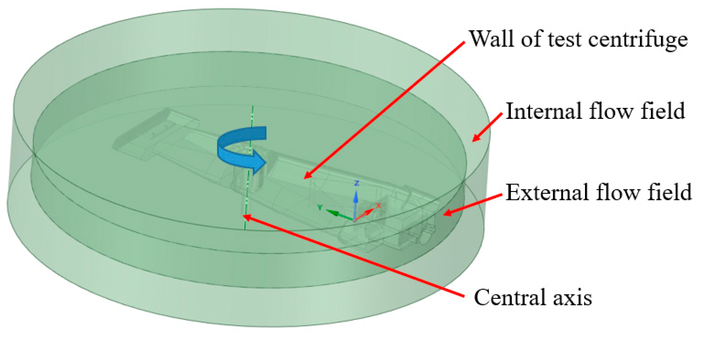
Figure 9.
Vortex core diagram: (a) Schematic diagram of the vortex core area; (b) Schematic diagram of the vortex core area after adding the whole package shell.
Figure 9.
Vortex core diagram: (a) Schematic diagram of the vortex core area; (b) Schematic diagram of the vortex core area after adding the whole package shell.
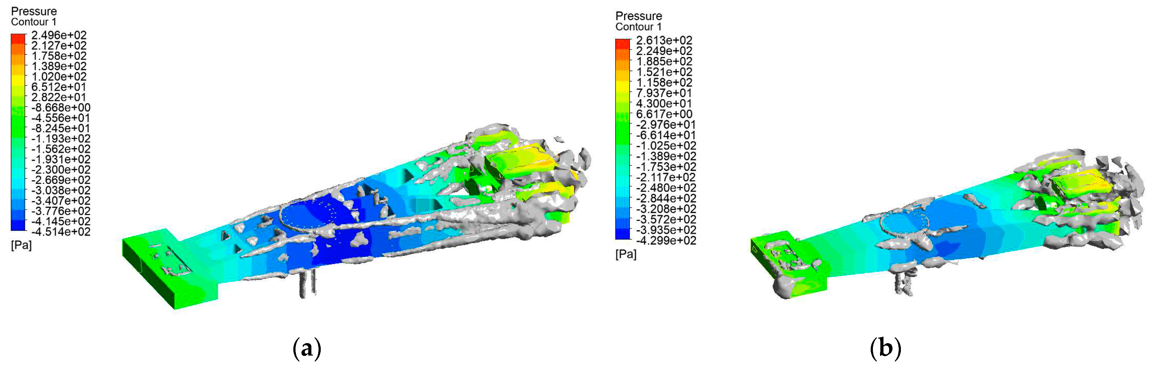
Figure 10.
Vortex core diagram: (a) Three-dimensional model of test centrifuge with whole package shell; (b) Test centrifuge with a steady flow shell.
Figure 10.
Vortex core diagram: (a) Three-dimensional model of test centrifuge with whole package shell; (b) Test centrifuge with a steady flow shell.
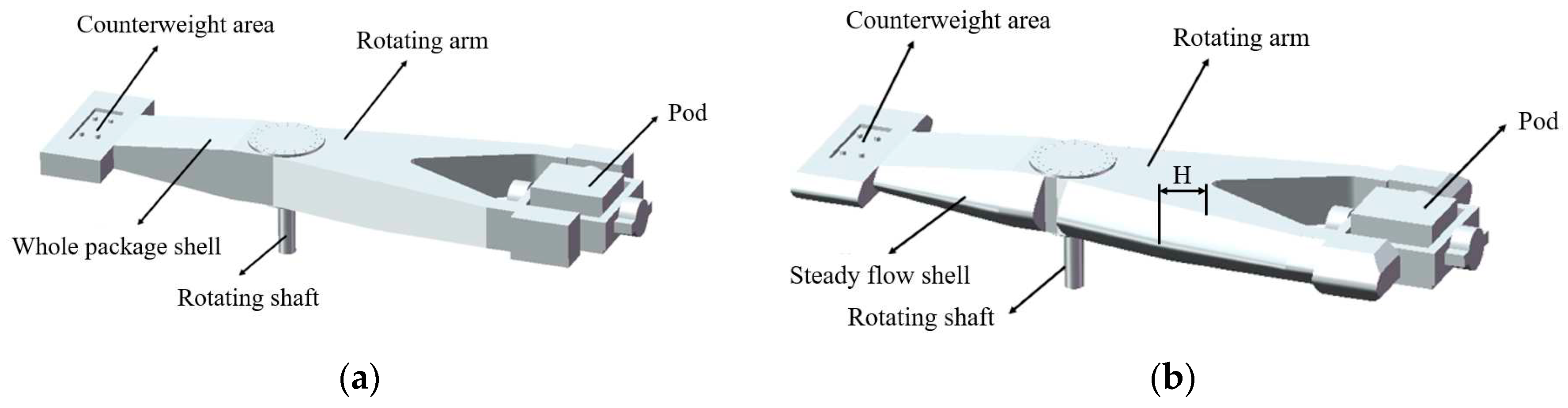
Figure 11.
Drag coefficients of different extension widths.
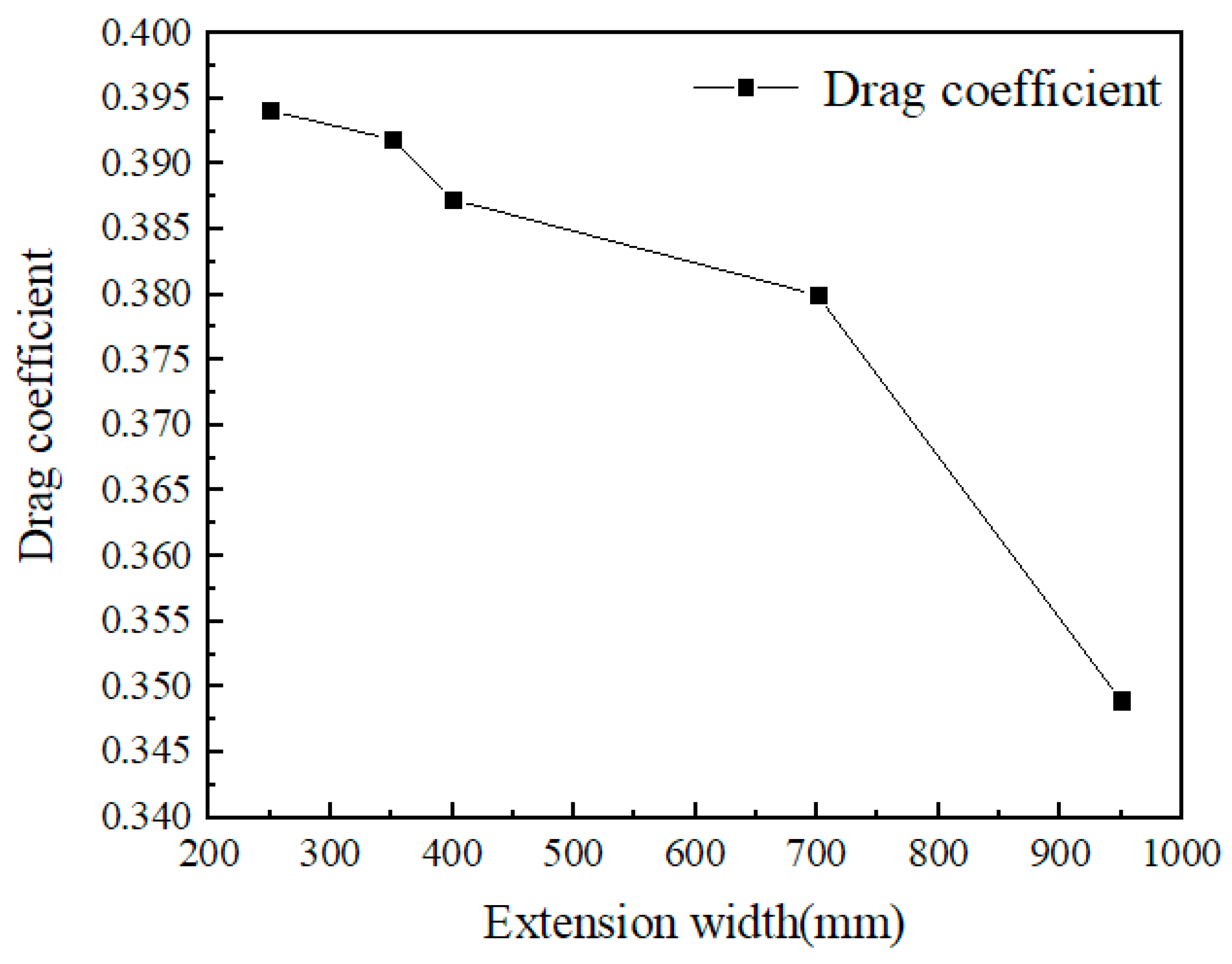
Table 2.
Harmonic response analysis results.
| Incentive type | Mounting seat vibration (mm/s) |
|---|---|
| Unbalanced excitation | 2.4998 |
| External vibration excitation | 0.0230 |
| Bearing vibration | 5.2242 |
| Total | 7.747 |
Table 3.
The harmonic response analysis results of the optimized mounting seat.
| Incentive type | Mounting seat vibration (mm/s) |
|---|---|
| Unbalanced excitation | 0.019 |
| External vibration excitation | 0.915 |
| Bearing vibration | 0.820 |
| Total | 1.754 |
Table 4.
Test centrifuge geometric parameters and operating conditions.
| Incentive type | Mounting seat vibration (mm/s) |
|---|---|
| Test centrifuge running space diameter/m | 22 |
| Test centrifuge running space height/m | 5 |
| air density/(kg/m3) | 1.205 |
| temperature/℃ | 20 |
| Test centrifuge rotating speed/rpm | 38 |
Table 5.
Average flow rate under two models.
| Flow analysis model | Average flow velocity(m/s) |
|---|---|
| Whole package shell + steady flow shell | 16.67 |
| Whole package shell | 17.02 |
Table 6.
Drag and lift forces under two models.
| Flow analysis model | Drag(N) | Lift(N) |
|---|---|---|
| Whole package shell + steady flow shell | 1469.67 | 96.61 |
| Whole package shell | 1885.19 | 204.30 |
Table 7.
Windward area under two models(m2).
| Flow analysis model | X-direction | Z-direction |
|---|---|---|
| Whole package shell + steady flow shell | 23.83 | 66.84 |
| Whole package shell | 23.60 | 47.79 |
Table 8.
Drag and lift coefficients under two models.
| Flow analysis model | Drag coefficient | Lift coefficient |
|---|---|---|
| Whole package shell + steady flow shell | 0.3796 | 0.0089 |
| Whole package shell | 0.4717 | 0.0252 |
Table 9.
Drag coefficients under five models.
| Extension width(mm) | Drag coefficient |
|---|---|
| 250 | 0.3941 |
| 350 | 0.3919 |
| 500 | 0.3873 |
| 700 | 0.38 |
| 950 | 0.349 |
Disclaimer/Publisher’s Note: The statements, opinions and data contained in all publications are solely those of the individual author(s) and contributor(s) and not of MDPI and/or the editor(s). MDPI and/or the editor(s) disclaim responsibility for any injury to people or property resulting from any ideas, methods, instructions or products referred to in the content. |
© 2023 by the authors. Licensee MDPI, Basel, Switzerland. This article is an open access article distributed under the terms and conditions of the Creative Commons Attribution (CC BY) license (http://creativecommons.org/licenses/by/4.0/).
Copyright: This open access article is published under a Creative Commons CC BY 4.0 license, which permit the free download, distribution, and reuse, provided that the author and preprint are cited in any reuse.