1. Introduction
Aluminium and its alloys have been extensively used in many areas of industry, such as automotive, aerospace, shipping, sports, electrical, machinery and petroleum, primarily because of their light weight, good weight-to-strength ratio, excellent electrical and thermal conductivity, low cost, and corrosion resistance in non-aggressive environments [
1,
2,
3,
4,
5,
6]. Although a thin oxide layer naturally formed on the surface of an aluminium alloy could partially prevent corrosion attack, it is still susceptible to deterioration when exposed to an aqueous solution containing Cl
-, F
-, I
- and Br
- ions [
1,
4,
5]. In addition, poor fatigue resistance, low surface hardness and wear resistance are also insufficient for many requirements [
3,
7,
8]. Therefore, additional surface protection of aluminium alloys is often essential and is usually achieved by various coatings applied on aluminium alloys [
1,
2,
5] or other surface processing techniques, such as different methods of shot peening [
4,
6,
7,
8,
9,
10,
11,
12,
13,
14] cavitation peening [
15] and surface remelting [
3,
16].
Shot peening (SP) is an effective surface treatment that improves the service life of components subjected to general fatigue as well as fretting fatigue by preventing crack initiation and propagation by improving the mechanical and physical properties [
17]. SP provides the creation of compressive residual stress and plastic deformation on the surface by bombarding spherical balls at certain speeds [
18]. Successful fatigue enhancement depends on a compromise between the compressive residual stress and the detrimental effect on surface quality [
13]. Due to the easiness of the process and no need to heat exposure, the SP could be applied to any complex and intrinsic shapes [
7].
Efe et al. [
7] studied a severe shot peening with an Almen intensity of 20 A on AA7075 aluminium alloy. They reported that two gradient layers are constructed: a deformed layer and a nanocrystalline layer. Microhardness is improved by 30 % on the treated surface but drops to less than 10 % after 600 µm depth. An improvement in fatigue behaviour is also observed after shot peening, although the roughness increases significantly. In addition, the friction coefficient of the treated specimens is generally lower and limited loads and excessive sliding distances could have a negative impact on the wear performance of shot peening, while an increase in the sliding distance leads to the disappearance of the influence of shot peening. Su et al. [
9] investigated conventional shot peening and micro-shot peening on bare and micro-arc oxidation coated 6082-T6 aluminium alloy. They concluded that micro-shot peening improves fatigue properties of bare specimens over conventional shot peening because it inhibits crack initiation, while for micro-arc oxidised alloys with stringent corrosion and abrasion resistance requirements, conventional shot peening improves fatigue properties better due to its inhibitory effect on crack propagation. However, conventional shot peening results in a deeper affected layer with higher compressive residual stresses, but on the other hand, the surface roughness increases due to large-size particles at high velocity, which inevitably weakens the improvement of fatigue properties. Wang et al. [
10] applied a novel coupled constitutive model to reveal the influence of different shot sizes on the microstructure of 2060 Al-Li alloy. Their results show that a larger shot size significantly improves the depth of the dislocation density layer and the fine-grain layer of 2060 Al-Li alloy.
Sun et al. [
11] studied the microstructure, corrosion behaviour, and thermal stability of the ultrasonic shot peened AA7150. They reported that the corrosion resistance of peened specimens in the environments was significantly improved in comparison with untreated specimens. The improved local corrosion resistance is a result of the formation of equiaxed nano-grains and the homogenization of the microstructure on the peened layer. Hao et al. [
14] also believed that low shock peening results in the prevention of formation and growth of corrosion pits. This is mainly due to grain refinement. Trdan et al. [
4] revealed that the corrosion resistance of AA2024-T3 could be improved by femtosecond laser peening in a 0.6 M NaCl test solution due to the compressive residual stress. Despite the improvement in corrosion resistance, Qiao et al. [
6] investigated the effect of shot peen forming on the corrosion resistance of 2024 aluminium alloy in a salt spray environment. It was reported that the salt spray corrosion resistance of 2024 aluminium alloy decreased after shot peening, with pitting corrosion occurring first in the crater lap zone and became more severe with increasing salt spray time.
Shot peening is often reported to increase the surface hardness, the compressive residual stress with associated high-density dislocation structures, improving fatigue and wear properties and extending the machine part's life. On the other hand, the increased surface roughness caused by shot peening can promote localized pitting corrosion. Therefore, the aim of this study is to investigate the effects of shot peening with various Almen intensities on strength and corrosion properties. Microhardness and residual stresses were performed to evaluate the strengthening properties. Besides, the corrosion properties were evaluated using open circuit potentials and cyclic potential scans.
2. Experimental Method
2.1. Specimen Preparation and Shot Peening
The substrate material used is a commercial EN AW 6082-T651 (AlSi1MgMn) aluminium alloy with the chemical composition shown in
Table 1. EN AW 6082 aluminium alloy was obtained in the T651 condition. This means that it was homogenized at a temperature of 540°C, then cold hardened with 1-3% deformation, and finally artificially aged or precipitation hardened at a temperature of 160°C for 10 hours. The mechanical properties of the aluminium alloy are listed in
Table 2.
In this study, a shot peening process with different parameters was chosen. The working medium was the same for all four settings of the working machine, having the designation S17056 HRC. On the label, the letter S (steel) stands for the type of particles and the number 170 for the diameter of the particles, which in our case is 0.4 mm. A common parameter in surface treatment was also a distance between the nozzle of the processing machine and the surface of the workpiece. The data on the parameters of shot peening are summarised in
Table 3.
2.2. Microstructural and Mechanical Analysis
To gain an insight into the microstructure, it is necessary to properly cross-sect the specimen and prepare the specimens for a metallographic analysis. The specimens were prepared by successive polishing with emery papers of different grits ranging from 320 to 800 μm in succession, followed by disk polishing with colloidal silica of 3 μm and 1 μm to obtain a mirror-finished surface. Finally, the polished specimens were etched with a solution of 5% HF + 95% water to visualize the microstructure. The microstructural observation was carried out on the cross-section of shot peened specimens using the optical microscope Olympus SZX10. By analysing the microstructure, we tried to determine the effects of particle collisions on the changes in the hardened surface layer.
Surface roughness measurements were conducted with a Surtronic 3+ profile meter (Taylor/Hobson Peumo) using a Gaussian filter with a cut-off λc = 0.8 mm to obtain the roughness profile and separate it from the waviness profile. The roughness parameters were calculated using the TalyProfile Silver 7.4 software. The surface roughness of the specimens was measured over a length of 8 mm with 10 repetitions on each specimen. The characteristics of the specimens selected for roughness evaluation SP are the mean arithmetic roughness Ra and the mean roughness depth Rz.
The level of plastic deformation is determined through surface hardness modifications and the hardness profile of the thin surface layer. Microhardness was measured with Vickers method at a load of 200 g (HV0.2). The microhardness profile started 25 μm below the surface with a step size of 25 μm for each subsequent measurement to a depth of 350 μm.
Residual stresses were measured in the middle of the specimen by means of the hole-drilling method in compliance with the ASTM E837 standard [
19]. The CEA-06-062UL-120 resistance-measuring rosettes manufactured by Vishay Precision Group and a drill of a 1.6 mm diameter were used to conduct the measurements. ReStress for WindowsTM Version 1.07, Vishay Group Inc. software was employed to measure the deformation and movement and to calculate the residual stress profile by applying the integral method.
2.3. Corrosion Analysis
The electrochemical corrosion properties of the untreated and shot peened specimens were evaluated using the VoltaLab 10 PGZ 100 equipment (Radiometer Analytical SAS) with the VoltaMaster 4 software according to the ASTM G5-14 standard [
20]. A classical three-electrode cell was used for the corrosion measurements. The reference electrodes were a saturated calomel electrode (SCE), and the working electrode was the untreated and shot-peened specimens embedded in PAR Teflon holders. The medium chosen for the study was a naturally aerated (pH = 7.5 ± 0.2, T=22.6 ± 0.3°C) 0.5M NaCl solution, freshly prepared with deionised water before each experiment, from laboratory grade NaCl (Sigma Aldrich). Immediately before each corrosion experiment, all specimens were cleaned and degreased in an ethanol containing ultrasonic bath followed by deionized water for 3 min each. Each experiment was conducted twice in the same manner; afterwards, the average of the data was calculated to ensure the reproducibility of the results.
The measurements of the open circuit potential (E
ocp = f[t]) were performed for 60 min to stabilize the surface, and corrosion potential (E
corr) was determined at the end of the stabilisation process. Following the OCP, CP scans were initiated towards anodic direction from -200 mV with respect to the OCP at a sweep rate of 1 mV/s. The polarization direction was reversed at the switching potential (E
sw), at which the potential reached a limited threshold of 1 mA/cm
2 and progressed in the cathodic direction toward the initial potential. Corrosion potential (E
corr) and corrosion current density (i
corr) were extracted by the Tafel extrapolation method [
21]. Furthermore, switching potential (E
sw) and the potential at which pits repassivate on reverse scan (E
prot) were also obtained. In order to obtain quantitative information, a protective efficiency (P
ef) was calculated using the following Equation (1) [
1,
5]:
where i
corr,0 and i
corr,N represent the corrosion current densities of the untreated and shot-peened aluminium specimens, respectively.
3. Results and Discussion
3.1. Microstructural and Surface Roughness Analysis
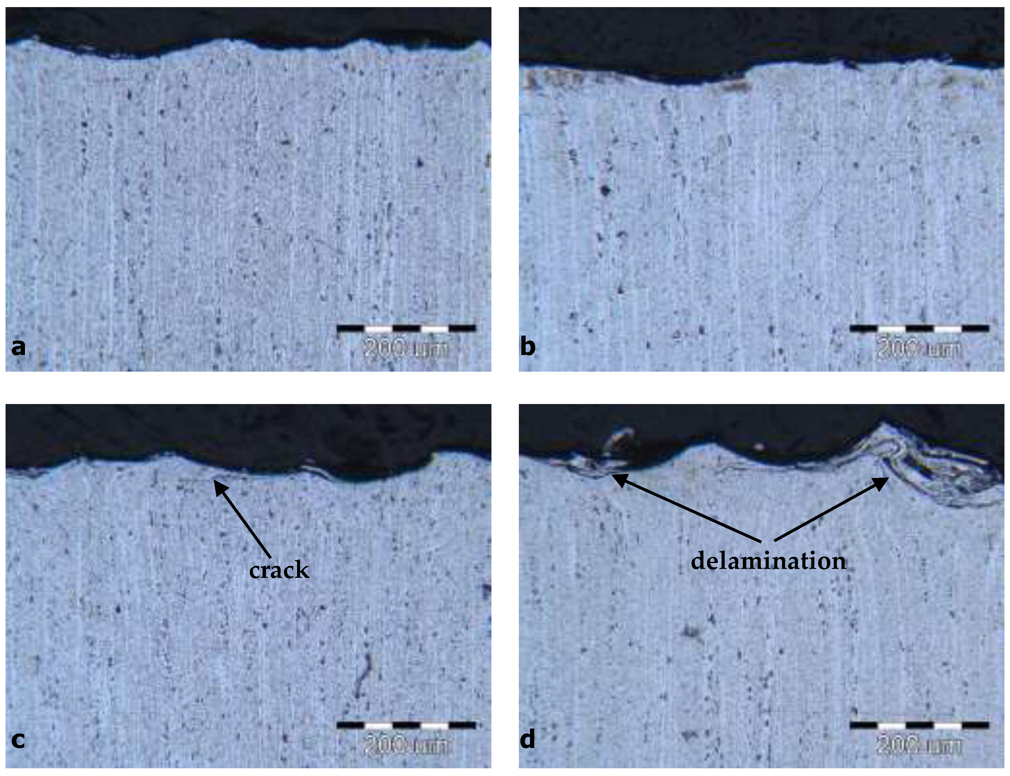
Figure 1 shows the microstructures of the SP specimens for each condition individually, revealing hardened precipitates and surface grooves at different working pressures. The microstructural images were taken directly below the surface. The microstructure of the specimens hardened under the hardest conditions.
Figure 1c,d shows cracks and delaminations in the surface layer, which represent the negative effects of hardening. No such defects can be seen in the microstructure of the specimens hardened at a working pressure of 1.6 bar (
Figure 1a,b). The effect of dislocation densification was confirmed by an additional measurement of microhardness above the hardened layer.
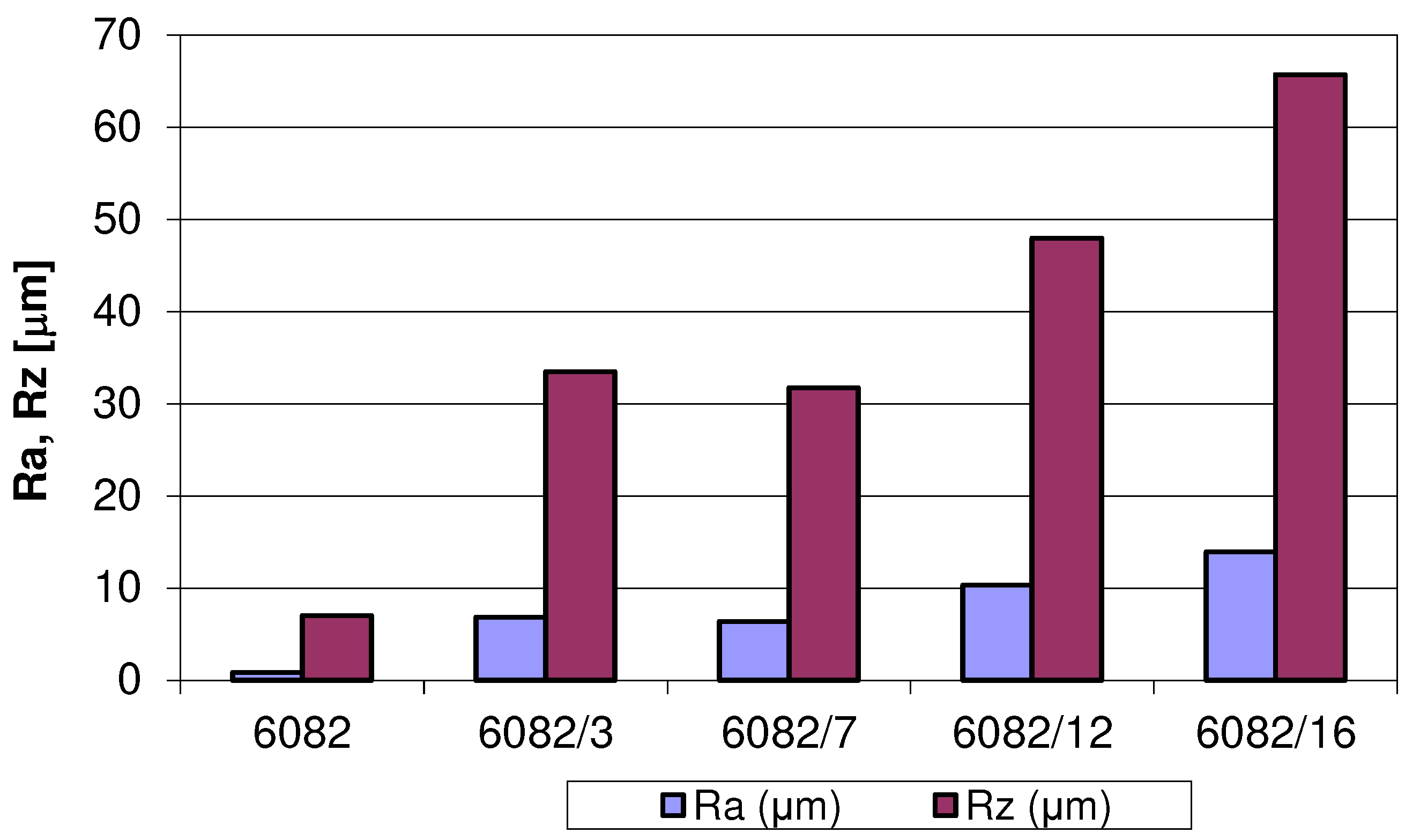
Shot peening changed the profiles of the treated surfaces under all machining conditions, which is also reflected in the calculated roughness parameters.
Figure 2 shows, in the form of bar graphs, the mean values of the arithmetic mean roughness (R
a) and the mean values of the roughness depth (R
z), which increase several times for all specimens compared to the untreated specimens. The R
a and R
z values of the untreated aluminium alloy were 0.85 μm and 6.99 μm, respectively.
From the surface roughness data, it follows that as the working pressure increases, the roughness of the hardened surface also increases. The specimens treated with the same working pressure of 1.6 bar, but with different mass flows, show no significant differences in the calculated surface roughness characteristics. The R
a and R
z values even slightly decrease (6.82 μm to 6.38 μm and 33.48 μm to 31.75 μm), when the mass flow rate is increased from 1 kg/min to 1.5 kg/min at the same pressure. For the specimens treated at higher working pressures (4 bar and 8 bar), which consequently means that the particles have higher kinetic energy, it was found that the roughness increases with the increased Almen intensity. The R
a and R
z values of the treated aluminium alloy at 4 bar were 10.33 μm and 13.93 μm, respectively, and for the treated alloy at 8 bar, the R
a and R
z values were 47.98 μm and 65.73 μm. An increase in roughness during hardening is characteristic of softer materials, including the tested EN AW 6082 aluminium alloy [
22].
3.2. Microhardness and Residual Stress Analysis
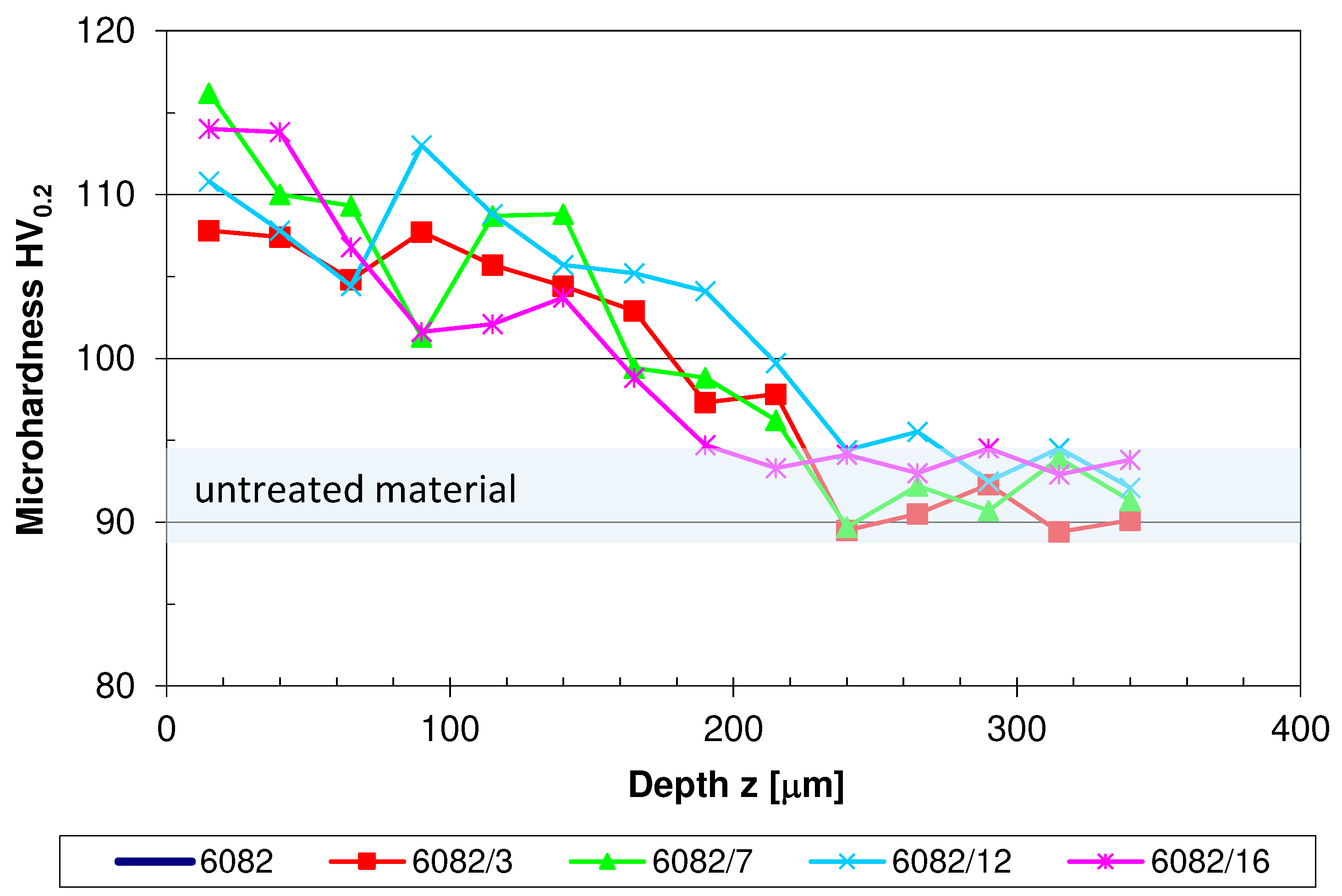
Figure 3 presents the microhardness profiles of the SP treated and untreated specimens. It is clearly seen that the microhardness is generally higher near the SP treated surface, while the microhardness decreases to the value of the base material with an increasing distance from the surface. The microhardness of the untreated material was between 89 HV
0.2 to 94 HV
0.2. The results in
Figure 3 show that the largest increase in microhardness due to SP was observed in specimen 6082/12 with a value of 116 HV
0.2 and the lowest in specimen 6082/3 with a value of 108 HV
0.2 compared to the untreated material.
Figure 4 shows the residual stresses for the treated and untreaded aluminium alloy EN AW 6082. The residual stresses initially increase or escalate in the pressure range up to the highest value, which lies at a depth between 400 μm and 600 μm, regardless of the hardening conditions.
Differences were found in the hardening depth and in the value of compressive stresses. For a specimen treated with the Almen intensity of 0.25 mmA at a depth of 700 μm, the maximum value of the compressive residual stress was -139 MPa. For a specimen treated with an intensity of 0.31 mmA, the compressive residual stresses increased more rapidly with an increasing depth of the hardened layer, reaching its maximum value at a depth between 400 μm and 700 μm. The maximum value was -162 MPa. When the intensity was increased to 0.70 mmA, the compressive residual stress profiles increased to a depth of 500 μm and then remained similar to the profiles in the previous specimen; however, the depth of the maximum compressive residual stress remained the same with a stress value of -225 MPa. At a treatment intensity of 0.53 mmA, the maximum residual stress value was reached at a depth of 500 μm, i.e. -231 MPa. The differences in residual stresses on the surface were up to 100 MPa. This difference increased at a depth of 500 μm, where the maximum stress values were reached regardless of the treatment conditions. The largest difference in stress values was between the 0.25 mmA and 0.53 mmA intensities. It was 120 MPa at a depth of 500 μm.
The applied compressive residual stresses reach 60-70% of the yield strength. Exactly these magnitudes were reached under the hardest conditions at working pressures of 4 bar and 8 bar.
3.3. Corrosion Analysis
The open circuit potential (OCP) refers to the thermodynamic equilibrium potential of the individual reactions, indicates the kinetic balance between anodic and cathodic reactions, and can be used to assess a tendency of a material to participate in an electrochemical reaction [
23]. In general, the more negative the OCP value of a working electrode, the higher its tendency to participate in the electrochemical corrosion reaction [
2].
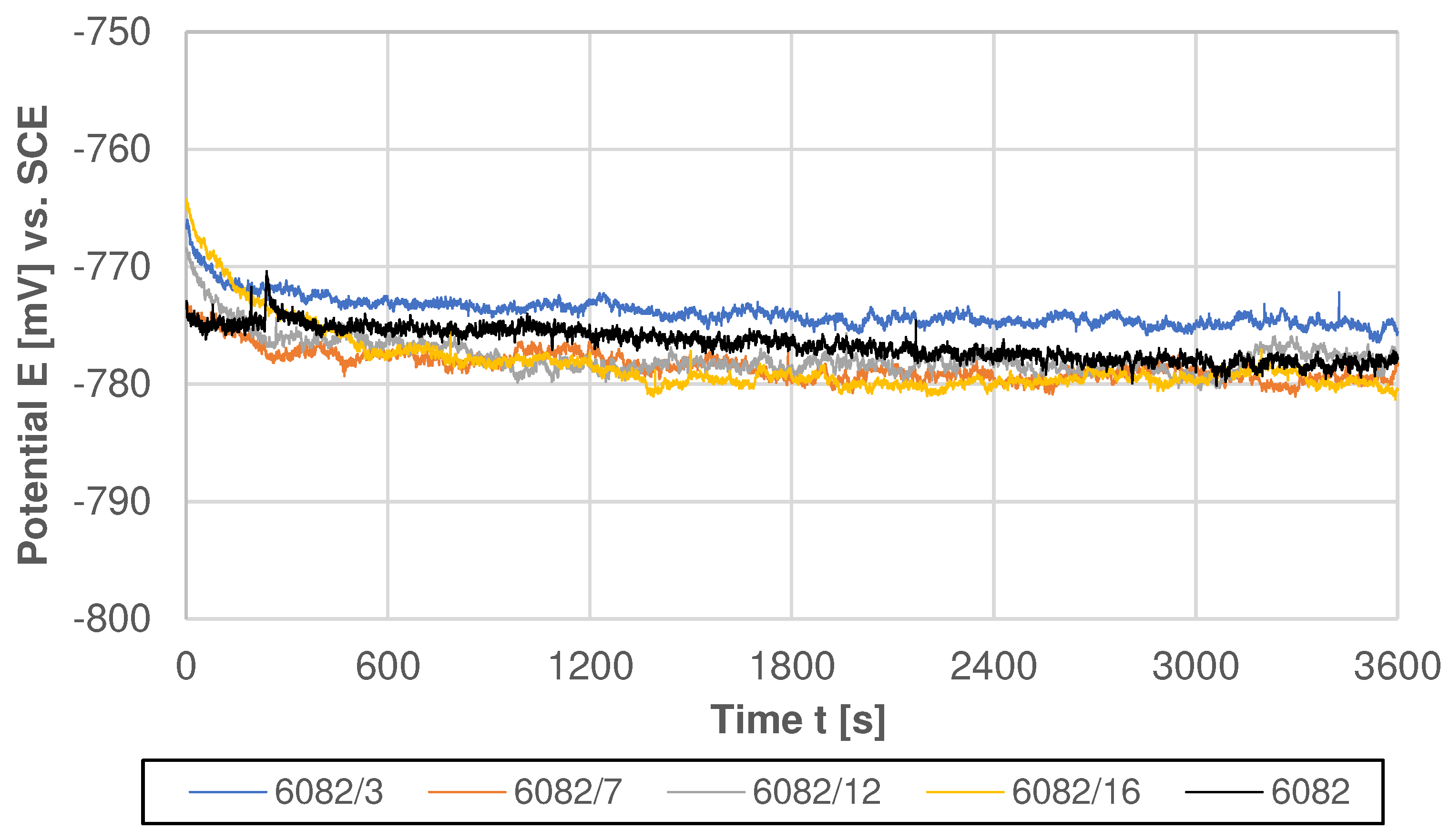
The OCP curves of the shot peened specimens and the untreated 6082 aluminium alloy in a 0.5 M NaCl solution are shown in
Figure 5.
As can be seen from the potential-time behaviour, all specimens showed a similar response during OCP testing with similar E
corr values at the end of the stabilization process (from -776 mV
SCE to -781 mV
SCE for shot peened specimens and -778 mV
SCE untreated specimen). When the specimens were immersed in an NaCl solution, all curves exhibited a slow potential decrease with slight fluctuations. The potential fluctuations are likely related to the increase in the active surface area due to the roughening effect during the shot peening process, or it could be possible dissolution/break down/rupture and partial repair/rebuilding of the surface oxide layer [
5,
24].
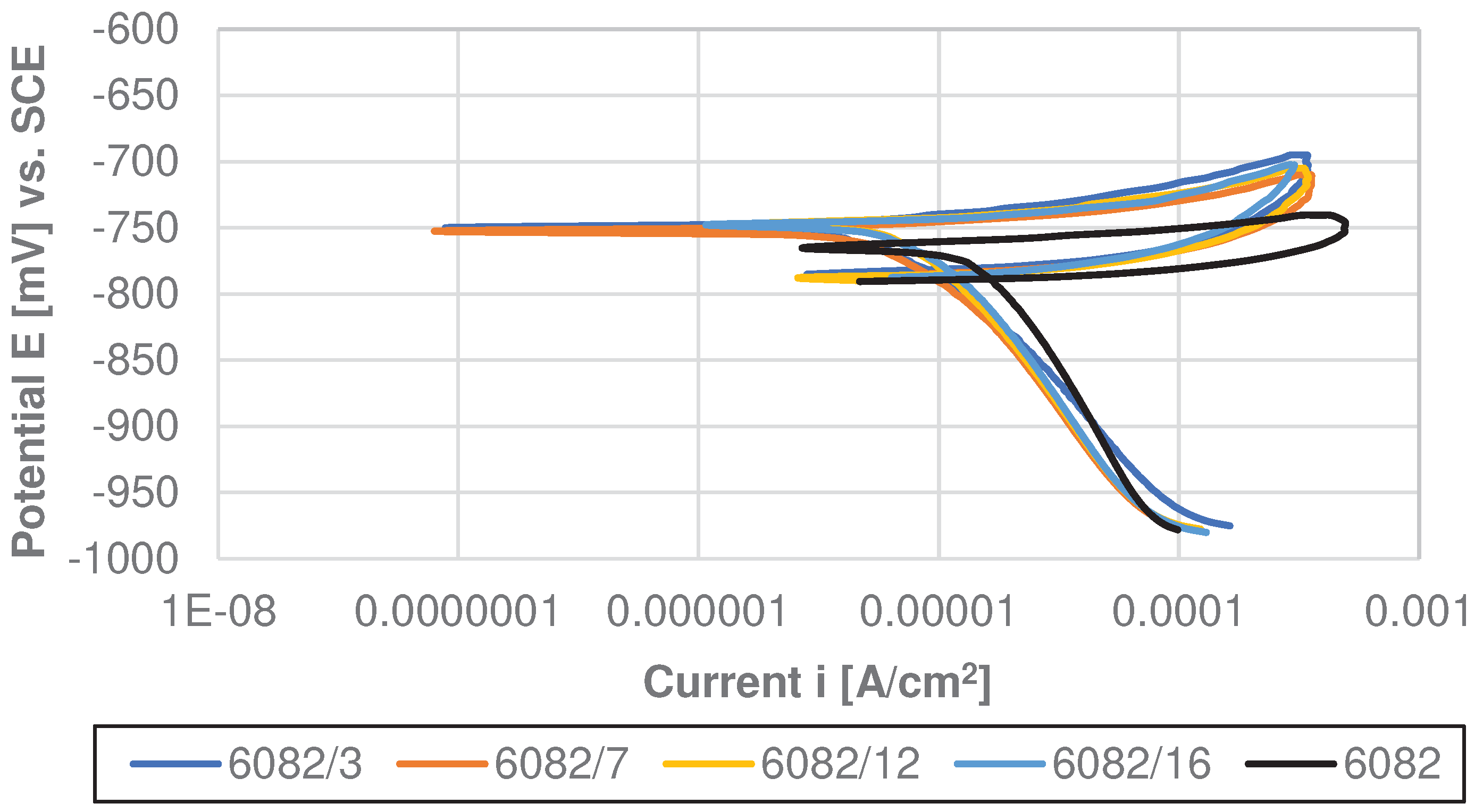
To further investigate the corrosion process, cyclic potentiodynamic (CP) scanning was recorded in a 0.5M NaCl solution. The CP method allows a quantitative assessment of the pitting resistance on the surface of aluminium alloys. In summary, a higher corrosion potential (E
corr) presents a lower corrosion tendency, whereas a lower corrosion current density (i
corr) corresponds to a lower corrosion rate [
1]. The polarization curves of the untreated specimens and shot peened specimens are shown in
Figure 6, and the fitted electrochemical parameters are listed in
Table 4.
CP curves of the shot peened specimens and a CP curve of the untreated specimen have a similar shape regardless of the specimen, where the cathodic curve intersects the forward anodic scan, confirming that all tested specimens are susceptible to pitting corrosion. However, there is a significant difference between the shot peened and untreated specimens. The CP curve of the untreated specimen presents a sharp increase in current during anodic polarization, while partial passivation is observed after the shot peening process, as the potential increases slightly with the increasing current density.
Furthermore, the experimental results confirm that the shot peening significantly affects the important corrosion parameters such as potential (E
corr) and corrosion current density (i
corr). The most negative E
corr value (-766 mV
SCE) was observed in the untreated specimen, while the noblest corrosion potential was exhibited by the shot peened specimens 6082/12 and 6082/16 (-74 mV
SCE). The current density i
corr of 6082/3 with the lowest surface roughness among the treated specimens was more than twice lower than the untreated specimen (9.7 μAcm
-2 vs. 22.5 μAcm
-2). The current density of the treated specimens increases with surface roughness, even specimen 6082/16 with the highest roughness has a current density 1.8 times lower than the untreated specimen (12.2 μAcm
-2 vs. 22.5 μAcm
-2). Clearly, all treated specimens improve corrosion resistance of Al 6082-T651 alloy. In addition, the results of the protective effect show a positive effect of shot peening, with the highest value of 57%, notwithstanding the higher roughness of the treated specimens compared to the untreated specimen. The most important parameters used to describe the resistance to the pitting corrosion in a chloride containing solution are |E
sw – E
corr| and |E
corr – E
prot| [
5]. A larger value of |E
sw – E
corr| indicates a lower degree of anodic dissolution of the material, while a smaller value of |E
corr – E
prot| presents an improved ability for material repassivation. From ΔE tendency results, it can be confirmed that all treated specimens provided a lower degree of anodic dissolution, while the untreated substrate provided a better and faster ability for repassivation.
Considering the CP result, it can be concluded that shot peening improved the corrosion resistance in comparison with the untreated aluminium alloy. These results are consistent with those of Sue et al. [
11] who showed that the corrosion resistance of AA7150 was significantly improved by ultrasonic shot peening in a 57 g/L NaCl + 10 mL/L H
2O
2 solution compared to its untreated counterpart, which was attributed to the formation of equiaxed nanograins and the homogenization of the microstructure on the peened layer. Furthermore, Trdan et al. [
4] reported in their study that the CP results confirmed a 4-times lower corrosion current density for the specimen peened with a femtosecond laser, assuming that the surface roughness is more than 2times lower after femtosecond laser peening compared to conventional shot peening.
4. Conclusions
Shot peening was produced on EN AW 6082-T651 aluminium alloy, which effectively improved residual stresses, microhardness, and corrosion resistance. Based on the results obtained, the following conclusions can be drawn:
The shot peening process was successfully produced with a working pressure of 1.6 bar without any defects. At a working pressure of 4 bar and 8 bar, cracks and delaminations appear in the surface layer which represent the negative effects of hardening.
With higher working pressure, surface roughness increases, which can promote localized pitting corrosion.
The shot peening process proved to be an effective method of producing high compressive residual stresses and increased hardness in the treated surface layer. Microhardness increased by up to 23% and the residual compressive stresses are deeper and higher than in an untreated aluminium alloy.
All treated specimens improve the corrosion resistance of Al 6082-T651 alloy, although the shot penning causes greater surface roughness. The untreated aluminium alloy revealed no passive behaviour, while the treated specimens exhibit partial passivation, all treated specimens have much lower corrosion current density (up to 2.3 times lower compared to the untreated aluminium alloy) and up to 57% protective effect.
All treated specimens provided a lower degree of anodic dissolution, while the untreated substrate provided a better and faster ability for repassivation.
Author Contributions
Conceptualization, D.R., S.Ž. and R.Š.; methodology, D.R. and S.Ž.; investigation, D.R. and S.Ž.; preparation of the original written draft, D.R. and S.Ž.; written review and editing, R.Š.. All authors read and agreed to the published version of the manuscript.
Acknowledgments
This work was partially funded by the Slovenian Research Agency (ARRS) under the research program P2-0270 Production systems, laser technologies and materials welding. Special thanks to Prof. Grum for establishing contact with the Metal Improvement Company. Also special thanks to Metal Improvement Company, Austria, for valuable technical assistance in selection of process parameters and application of shot peening treatment on all test specimens used in this work.
Conflicts of Interest
The authors declare that there are no conflicts of interest.
References
- Zhang, X.-F.; Li, X.-D.; Wang, N.; Liu, Y.J.; Tian, F.; Wang, C.-X. Robust superhydrophobic Sio2/epoxy composite coating prepared by one-step spraying method for corrosion protection of aluminum alloy: Experimental and theoretical studies. Materials & Design 2023, 228, 111833. [Google Scholar] [CrossRef]
- Zhang, S.; Wang, C.; Zhao, S.; Niu, A.; Ma, Y. Enhanced long-term corrosion of 2A14 aluminium alloy: Hybrid effect of micro-arc oxidation coating and cerium based conversion treatment. Surface & Coatings Technology, 2023, 464, 129579. [Google Scholar] [CrossRef]
- Chen, R.; Wang, H.; Li, J.; He, B.; Shao, W.; Zhang, S. Effect of laser remelting and heat treatment on microstructure and wear resistance of 2A97 Al-Li alloy. Surfaces and Interfaces 2022, 33, 102197. [Google Scholar] [CrossRef]
- Trdan, U.; Sano, T.; Klobčar, D.; Sano, Y.; Grum, J.; Šturm, R. Improvement of corrosion resistance of AA2024-T3 using femtosecond laser peening without protective and confining medium. Corrosion Science 2018, 143, 46–55. [Google Scholar] [CrossRef]
- Rajamure, R.S.; Vora, H. D.; Srinivasan, S.G.; Dahotre, N.B. Laser alloyed Al-W coating on aluminium for enhanced corrosion resistance. Applied surface science 2015, 328, 205–214. [Google Scholar] [CrossRef]
- Qiao, J.; Zhang, X.; Chen, G.; Zhou, W.; Fu, X.; Wang, J. Effect of Shot Peen Forming on Corrosion-Resistant of 2024 Aluminum Alloy in Salt Spray Environment. Materials 2022, 15(23), 8583. [Google Scholar] [CrossRef] [PubMed]
- Efe, Y.; Karademir, I.; Husem, F.; Maleki, E.; Unal, O. Surface Severe Plastically Deformed Nanostructured AA7075 Alloy: Assessment on Tribological and Axial Fatigue Behaviors. Journal of Materials Engineering and Performance 2020, 29, 3774–3783. [Google Scholar] [CrossRef]
- Trdan, U.; Skraba, M.; Porro, J.A.; Ocana, J.L.; Grum, J. Application of massive laser shock processing for improvement of mechanical and tribological properties. Surface and Coatings Technology 2018, 342, 1–11. [Google Scholar] [CrossRef]
- Su, K.; Zhang, J.; Li, H.; Ji, D.; Hu, L. Anti-fatigue strengthening mechanism of conventional shot peening and micro-shot peening on bare and micro-arc oxidation coated 6082-T6 aluminium alloy. Materials Letters 2023, 331, 133442. [Google Scholar] [CrossRef]
- Wang, Z.; Xie, L.; Zhang, Q.; Ali, R.A.; Chen, W.; Zhou, L. Surface layer strengthening mechanism of 2060 aluminum–lithium alloy after shot-peening. Journal of Materials Research and Technology 2023, 23, 4615–4633. [Google Scholar] [CrossRef]
- Sun, Q.; Han, Q.; Wang, S.; Xu, R. Microstructure, corrosion behaviour and thermal stability of AA 7150 after ultrasonic shot peening. Surface and Coatings Technology 2020, 398, 26127. [Google Scholar] [CrossRef]
- Su, C.-H.; Chen, T.-C.; Ding, Y.-S.; Lu, G.X.; Tsay, L.-W. Effects of Micro-Shot Peening on the Fatigue Strength of Anodized 7075-T6 Alloy. Materials 2023, 16(3), 1160. [Google Scholar] [CrossRef] [PubMed]
- Trsko, L.; Guagliano, M.; Bokuvka, O.; Novy, F.; Jambor, M.; Florkova, Z. Influence of Severe Shot Peening on the Surface State and Ultra-High-Cycle Fatigue Behavior of an AW 7075 Aluminum Alloy. Journal of Materials Engineering and Performance 2017, 26, 2784–2797. [Google Scholar] [CrossRef]
- Hao, W.; Ning, C.Y.; Huang, Y.H.; Cao, Z.Y.; Chen, X.X.; Zhang, W.W. Improvement of abrasion resistance in artificial seawater and corrosion resistance in NaCl solution of 7075 aluminum alloy processed by laser shock peening. Optics and Lasers in Engineering 2017, 90, 179–185. [Google Scholar] [CrossRef]
- Soyama, H. Cavitation Peening - A review. Metals 2020, 10(2), 270. [Google Scholar] [CrossRef]
- Chen, S.; Richter, B.; Morrow, J.D.; Sridharan K.; Pfefferkorn, F.E.; Eriten, M. Pulsed laser remelting of A384 aluminum, part I: Measuring homogeneity and wear resistance, Journal of Manufacturing Processes 2018, 32, 606-614. [CrossRef]
- Avcu, Y.Y.; Yetik, O.; Guney, M.; Iakovakis, E.; Sınmazçelik, T.; Avcu, E. Surface, Subsurface and Tribological properties of Ti6Al4V alloy shot peened under different parameters. Materials 2020, 13(19), 4363. [Google Scholar] [CrossRef] [PubMed]
- Unal, O.; Maleki, E.; Karademir, I.; Husem, F.; Efe, Y.; Das, T. Effects of conventional shot peening, severe shot peening, re-shot peening and precised grinding operations on fatigue performance of AISI 1050 railway axle steel. International Journal of Fatigue 2022, 155, 106613. [Google Scholar] [CrossRef]
- Standard Test Method for Determining Residual Stresses by the Hole Drilling Strain Gage Method, ASTM E 837-08, 2008.
- ASTM G5-14; Standard Reference Test Method for Making Potentiodynamic Anodic Polarization Measurements. ASTM International: West Conshohocken, PA, USA, 2014.
- Chi, G.; Yi, D.; Liu, H. Effect of roughness on electrochemical and pitting corrosion of Ti-6Al-4V alloy in 12 wt.% HCl solution at 35°C. Journal of Material Research and Technology 2020, 9, 1162–1174. [Google Scholar] [CrossRef]
- Shulze, V. Modern Mechanical Surface Treatment: States, Stability, Effects, WILEY-VCH Verlag Gmbh & Co. KGaA, 2005.
- Gowtham, S.; Arunnellaiappan, T.; Rameshbabu, N. An investigation on pulsed DC plasma electrolytic oxidation of Cp-Ti and its corrosion behaviour in simulated body fluid. Surface and Coating Technology 2016, 301, 63–73. [Google Scholar] [CrossRef]
- Li, D.; Lang, Y.; Liu, X.; Zhou, Y. Corrosion behavior of Ti3AlC2 in NaOH and H2SO4. Journal of the European Ceramic Society 2010, 30, 3227–3234. [Google Scholar] [CrossRef]
|
Disclaimer/Publisher’s Note: The statements, opinions and data contained in all publications are solely those of the individual author(s) and contributor(s) and not of MDPI and/or the editor(s). MDPI and/or the editor(s) disclaim responsibility for any injury to people or property resulting from any ideas, methods, instructions or products referred to in the content. |
© 2023 by the authors. Licensee MDPI, Basel, Switzerland. This article is an open access article distributed under the terms and conditions of the Creative Commons Attribution (CC BY) license (http://creativecommons.org/licenses/by/4.0/).
