
Submitted:
09 June 2023
Posted:
12 June 2023
You are already at the latest version
Abstract
Given the existing movable rotating plate type grading device for potatoes with a high safety factor and heavy mass, the body frame of the grading device and movable rotating plate were optimized and a lightweight design was carried out. Based on ANSYS Workbench 2022, the static analysis of the body frame before and after improvement was compared, and it was verified that the strength and deformation of the optimized body frame met the design requirements, and the weight of the optimized body frame was reduced by 32.3%. Based on the direct optimization module of ANSYS Workbench 2022, the plate length, width, and height were used as design variables for the lightweight design of the movable rotating plate. The MOGA algorithm was used to generate sixty design solutions, and the optimal combination of size parameters for the plate was 610 mm, 95mm, and1.2 mm. Compared with the whole grading device before optimization, the total mass was reduced by 22.86% after optimization. The research of this article provides a reference for the structural design and optimization analysis of potato grading devices.
Keywords:
movable rotating plate
; potato
; grading
; optimization
; ANSYS Workbench
1. Introduction
Potato is one of the world's most important food crops. China's potato cultivation area is located in the world's first, but the potato mechanization production degree is low. Potato mechanization research has been urgent with the potato staple food strategy promoted [1,2,3]. Potato grading devices are necessary equipment in potato harvesting, and related scholars have conducted extensive research. Currently, there are roller shaft-type, screen-type, and drum-type grading devices for potatoes [4]. These three grading devices in the grading process on the potato damage, grading grade less and grade adjustment is more complicated, seriously affecting the efficiency of potato grading [5,6,7]. Therefore, we researched and designed the movable rotating plate type grading device for potatoes, which adopted a movable rotary plate with an adjustable gap, high grading efficiency, and three grading levels. Still, the grading device has a high safety factor and heavy mass, which needs to be optimized and improved.
The traditional optimization mode, which requires changes to the physical object, is time-consuming and costly. In contrast, the virtual simulation optimization design method can shorten the design cycle and save costs to a large extent [8]. There are more reports on virtual simulation optimization in China and abroad. Krasyuk A. M. et al. [9] used optimality criterion based on ANSYS software for the topology-optimized design of axial fan blades with a 60% reduction in blade mass. Yan[10] conducted the lightweight design of the frame of a tensile machine based on ANSYS Workbench, the equivalent force and total deformation of the optimized model were reduced, and the weight was reduced by 7.11%. Ma et al. [11] optimized the frame of a light truck based on ANSYS using the homogenization method to obtain an optimized frame topology that satisfied the volume constraint and minimized the total flexibility. Gadwala William Kery et al. [12] carried out the optimization of a sports car rim using ANSYS Workbench finite element analysis, which identified carbon fiber as a feasible material for manufacturing the sports car rim. Jackis Aukah et al.[13] optimized a husked corn dryer using ANSYS Workbench, and found that the air velocity at the collector inlet and biomass heat exchanger outlet should be increased to 3m/s and 2.8m/s, respectively. Muhammad Aisha et al. [14] used the finite element method in ANSYS Workbench to optimize the topology of a steering knuckle, and the optimization determined the mass to be removed. Similarly, Sharma M P et al. [15] used CREO2.0 in combination with ANSYS workbench to optimize the shape of the automotive steering knuckle. Jha et al. [16] used CATIA in combination with ANSYS Workbench to optimize and improve the steering knuckle. Li et al. [17] improved and optimized the base structure of the welding robot based on ANSYS Workbench. The original model was analyzed and compared with the improved and optimized solution, and the expected optimization objectives were achieved. Feng et al. [18] used ANSYS Workbench to optimize the design of the fan base of the motor, and the structural stresses under various operating conditions were simulated and verified. Li Chuchen et al. [19] used ANSYS Workbench's response surface optimization for the lightweight design of a particular vehicle's on-board lens, and the lens's total mass was reduced by 20.69% after optimization. Li Xiang et al. [20] optimized the potato excavator suspension based on ANSYS Workbench and the response surface method and obtained the optimized suspension thickness, which can effectively reduce the deformation.
The analysis of the existing studies shows that the virtual simulation optimization design method, which can be cost-saving and high efficiency, has rarely been reported for the optimization design of potato grading devices. Therefore, given the problems of high safety factor and heavy mass of the existing movable rotating plate type grading device for potatoes, this article uses the virtual simulation optimization method based on ANSYS Workbench 2022 to optimize the design of the body frame and movable rotating plate to reduce the weight while the strength and deformation meet the design requirements.
2. Materials and Methods
2.1. Movable Rotating Plate Type Grading Device for Potato
A movable rotating plate type grading device for potatoes (shown in Figure 1), according to the movable rotating plate gap size as a way to grade potatoes, shows its grading principle schematic diagram in Figure 2. The movable rotating plate moves in a cycle with the conveying chain, and the bottom is in contact with the slide rails on both sides. With the change in the tilting angle of the slide rails, the gap between adjacent rotating plates gradually increases. Potatoes of different sizes fall into the potato-collecting device from different gaps.
The body frame (shown in Figure 3) is composed of the chain fixing part and the base. The chain fixing part mainly plays the role of fixing the chain and the movable rotating plate assembly, which is made of square steel pipe welded together, and the steel plate is welded on the steel pipe to fix the bearing seat. The size of the square steel pipe is 40×40×4(mm), and the thickness of the steel plate is 8mm. The base is made of rectangular steel pipe welded together, which is 40×30×3(mm).
The size of the body frame is 1400×896×780 (mm), and the total mass is 157.82 kg. Given its high safety factor and large overall mass, it is designed to be lightweight.
The movable rotating plate (shown in Figure 4) consists of a rotating plate movable shaft, rotating plate, and rotating plate friction shaft, which are connected by welding. The rotating plate movable shaft is the central part that connects the rotating plate and the chain. It is connected to the bracket on the chain part and drives the movement of the rotating plate. The rotating plate friction shaft is in contact with the slide rail, and its main role is to avoid direct contact between the rotating plate and the slide rail, resulting in the wear deformation of the rotating plate.
The size of the existing rotating plate is 640×95×2 (mm) in length, width, and thickness, respectively, and the total mass of the single movable rotating plate is 1.7449kg. There are 32 groups of movable rotating plates in the machine, which causes the heavy mass and inconvenient for operation.
2.2. Static Analysis of Existing Body Frame
2.2.1. Analysis of Load on the Body Frame
2.2.2. Pre-Processing of the Static Analysis of the Body Frame
According to the design requirements, the material of the body frame is Q235, and the material properties are shown in Table 1.
The parts of the body frame are welded and bolted together, so the contact setting is "binding."
When analyzing in ANSYS, the mesh division's size and the mesh division's quality at key locations will directly affect the accuracy of the analysis results [21]. The dense the mesh division, the more accurate the calculation results, but the calculation volume will increase [22]. The overall tetrahedral meshing method is adopted for the frame, the order of the elements is selected as second order, and the mesh cell size is set to 8mm.The critical position of the force contact is in the bearing seat, so the mesh cell size is set to 3mm. The completed meshing generates 1628000 nodes and 888646 cells.
Fixed supports are set on the bottom surface of the six foot seats of the body frame and force are applied to the eight bearing surfaces with a total combined force of 1473.75 N, i.e., 184.21875 N on each surface, and the direction is vertically downward.
2.2.3. Solving
The total deformation and equivalent Von-Misses stress of the body frame were solved and the clouds of the total deformation and equivalent Von-Misses stress were shown in Figure 7.
The total deformation cloud diagram showed that the deformation at the upper steel tube of the body frame was more significant, the overall deformation gradually decreased from top to bottom, and the maximum deformation was 0.0047894 mm. The equivalent stress cloud diagram showed that the stress was mainly concentrated on the eight bearing positions and the four vertical beams of the base, and the maximum stress value was 5.5037 MPa.
Based on the above analysis results, it was seen that the existing body frame met the strength requirements, the safety factor was relatively high, and the redundancy is high. Therefore, there was a large space for the lightweight optimization of the body frame.
2.3. Static Analysis of Existing Movable Rotating Plate
2.3.1. Calculation of the Load on the Movable Rotating Plate
During the movement of the rotating plate, the angle between the rotating plate and the horizontal plane is continuously changing from 0 to 90 degree. When the rotating plate is parallel to the horizontal plane, the maximum load is applied. To obtain the maximum load, the whole surface of the rotating plate is covered with potatoes (Figure 8) and the total mass is 2.63 kg, which equals to 25.8N.
2.3.2. Statics Analysis Pre-Processing of Movable Rotating Plate
According to the design requirements, the material of the movable rotating plate is Q235, and the material-related parameters are the same as the body frame.
The movable shaft, the friction shaft, and the rotating plate are welded together so they are "bound" to each other. The mesh division method is "automatic" , the mesh cell size is set to 2mm, and the mesh division generates 426133 nodes and 250562 cells.
During the static analysis, the fixed constraints are applied to the connection between the rotating plate and the chain, as well as the contact position with the slide rail. The force applied to the movable rotating plate is 25.8N, and the direction is perpendicular to the rotating plate downward.
2.3.3. Solving
The total deformation and equivalent Von-Misses stress were analyzed in the solution option, and the clouds of the total deformation and equivalent Von-Misses stress were derived, as shown in Figure 9.
The total deformation obtained from the simulation results showed that the deformation mainly occurred in the middle part of the rotating shaft, rotating plate, and friction shaft. The overall deformation increased gradually from the two ends of the movable rotating plate to the middle part, reaching the maximum deformation of 0.10513mm in the central part.
The analysis of the equivalent Von-Misses stress diagram showed that the stress was mainly concentrated in the two ends of the rotating shaft and the friction shaft. The main reason was that the two ends of the movable rotating plate shaft were connected to the bracket, which caused the stress concentration during the movement. However, the friction shaft was contacted with the sliding rail, and there was also stress concentration during the movement. The maximum stress was 9.8396MPa, which was less than the material yield strength of 235MPa.
According to the above analysis results, it can be seen that the movable rotating plate met the strength requirements, and the design can be optimized from the perspective of dimensional parameters.
3. Results and Discussion
3.1. Body Frame Optimization Design
3.1.1. Body Frame Structure Improvement
The wall thickness of the square steel pipe, which is composed of the body frame, is an essential factor affecting the quality of the structure, so the wall thickness is changed from 4mm to 2mm. The overall body frame has six 8mm thick side plates, which are mainly used to fix the bearing seat and chain brace. Considering its high safety factor, the wall thickness of the side plates is changed to 5mm. The base is an important part bearing the whole machine, and the structure is also improved for optimization. The optimized body frame is shown in Figure 10, and the total mass is 106.84kg.
3.1.1. Static Analysis of Improved Body Frame
The optimized body frame was subjected to static structural analysis with the same mesh division, fixed supports, and load constraints as the body frame before optimization, and the total deformation and equivalent Von-Misses stress analysis results were obtained, which were shown in Figure 11.
The maximum total deformation of the final optimized rack is 0.0063963mm, and the maximum equivalent Von-Misses stress is 4.8083MPa. The deformation was still in the middle part of the steel tube above the frame, but the total deformation was minor. The stress was concentrated on the bearing position and the vertical beam of the frame base, and the stress was much smaller than the yield stress.
In summary, the optimized body frame met the strength requirements and the machine's total mass reduced significantly. A comparison of the relevant parameters before and after the optimization of the body frame was shown in Table 2, and the total mass was reduced by 32.3% compared with the pre-optimized frame.
3.2. Optimized Design of the Movable Rotating Plate
3.2.1. Rotating Plate Friction Shaft Improvement
The existing rotating plate friction shaft is Φ9mm in diameter and 640mm in length. In view of its contact position with the slide rail only at the two ends, the friction shaft can be split into two sections, and the length of each section is 50mm. The schematic diagram of the improved friction shaft is shown in Figure 12.
3.2.2. Size Optimization of Rotating Plate
To facilitate optimization and simplification of the model, the rotating plate friction shaft of the rotary plate was not modeled for the time being. The improved model of movable rotating plate was established in SolidWorks, and the length, width, and thickness of the rotating plate was define as the design variables based on the configuration requirements of the Workbench optimization module[23,24], as shown in Table 3.
The improved model can be imported directly into Workbench using the interface between SolidWorks and Workbench for static structural analysis. According to the design requirements, Q235 was selected as the material for the movable rotating plate. The design variables were selected in the Design Modeler, and the model was then ready for static structural analysis.
The rotating shaft and rotating plate were welded, so they were "bound" contact. The mesh division method used "Automatic." The mesh cell size was set to 2mm, and 211,015 nodes and 80,593 cells were generated by grid division. The grid quality of the movable rotating plate met the requirements through the verification of grid evaluation statistics provided by Workbench.
The fixed restraint and load applied to the movable rotating plate were the same as in the previous section.
The model's total deformation and equivalent Von-Misses stress were analyzed in the solution option, and the clouds of the total deformation and equivalent Von-Misses stress were derived, as shown in Figure 13.
The total deformation cloud obtained from the simulation results showed that the main deformation occurred in the middle part of the rotating plate and the central part of the rotating shaft, and the maximum deformation was 0.14022 mm. The results of the equivalent Von-Misses stress showed that the maximum stress value was 14.556 MPa.
3.2.3. Build the Mathematical Optimization Model
Structural optimization is usually done by varying the design variables to optimize the structure without affecting its performance and to satisfy the constraints[25]. By changing the dimensional parameters of the rotating plate, the mass is reduced as much as possible while ensuring that the deformation and stresses are within the safety factor.
This optimization design uses the direct optimization module in Workbench to optimize the design and seek the optimal combination of the dimensional parameters of the rotating plate. Therefore, the length P1, width P2, and thickness P3 of the rotating plate are design variables, and the setting of size range was mainly determined based on usage and manufacturing requirements. The maximum deformation P4, the maximum equivalent force P5 and the mass P6 are used as the optimization objectives, where the stress is taken as a safety factor of 1.5 to obtain the allowable stress of 156 MPa, i.e., the minimum stress must not exceed 156 MPa. The following mathematical model for optimization design is derived:
3.2.4. Building a Direct Optimization Model
The optimization algorithm must first be defined to establish a direct optimization model. Based on the optimization requirements of multiple independent variables and multiple objective functions in this article, the MOGA algorithm was used for optimization analysis, which supported multiple objectives and constraints, required continuous input parameters, and was well suited for calculating global maxima or minima, to find the global optimum while circumventing the pitfalls of local optima [26,27]. In the MOGA algorithm setup, the initial sample capacity was set to 100, the number of samples generated per iteration was 50, the maximum number of iterations was 20, and the maximum number of candidates was 3.
The objectives and constraints were set based on the above mathematical model for the rotating plate's length P1, width P2, and thickness P3. The optimization scheme was updated after the parameter setting, and then the solution started.
The total deformation, equivalent Von-Misses stress, and mass of the model for the different cases of length, width, and thickness of the rotating plate were obtained by analyzing the generated 60 sets of design solutions, as shown in Table 4.
3.2.5. Analysis of Optimization Results
The optimization state converged in 1 iteration with 0 failure points, and three sets of optimal solutions were obtained, as shown in Table 5.
Candidate point 1 was selected as the final optimization solution. Comparing the design variables and target variables before and after optimization, it can be seen that the mass is reduced by 28.7%, although the deformation was increased by 0.1mm. The stress was increased by 12MPa. It was still within the design allowance and met the strength requirements of the movable rotating plate. The reliability and safety were all in line with the requirements, and the comparison of the parameters before and after the optimization of the rotating plate was shown in Table 6.
As described in the previous section, ANSYS workbench for the optimized design of the movable rotating plate, the rotating plate friction shaft was not modeled and optimized, but the structure was improved directly, so after the optimization of the rotating plate, the rotating plate friction shaft was added for finite element analysis, and the final optimized results of the movable rotating plate were obtained, as shown in Figure 14.
According to the results of static analysis, the maximum deformation of the final optimized movable rotating plate was 0.76938mm, the maximum stress value was 86.144Mpa, and the minimum safety factor was 2.9718. The more considerable deformation is still in the middle part of the rotating plate, but it still meets the safety strength requirements. The stress was mainly concentrated on the rotating plate movable shaft and the rotating plate friction shafts of the rotating plate. Considering the real situation, the rotating plate movable shaft need to be bolted, and the friction shaft of the Rotating plate friction shaft has friction with the slide rail, but the maximum stress was still less than the allowable stress of the material. The minimum safety coefficient also meets the design requirements.
4. Conclusions
The comparison of static structural analysis of the frame and movable rotating plate before and after optimization was shown in Table 7.
The total mass of the movable rotating plate before optimization was 1.7449kg, and the total mass of the movable rotating plate after optimization was 1.0657kg, which reduced the mass by 38.9% and realized the light weight of the movable rotating plate. The maximum total deformation after optimization was 0.76938mm, which was within the reasonable deformation. The maximum equivalent force was 86.144MPa, which was within the yield limit of the material used and meets the strength requirement.
Before the optimization, the mass of the classifier was 320kg. After the optimization of the body frame and the movable rotating plate, the mass of the classifier was 246.8456kg, which was 22.86% lower than the mass of the whole machine.
Based on the direct optimization module provided by ANSYS Workbench, this article established the finite element model of the movable rotating plate and derived the optimal combination of dimensional parameters through finite element calculation simulation and verification. The accuracy, reliability, and practicality of the optimization method in this article needed more theoretical and practical further verification, and its method provided theoretical guidance for engineering design and structural optimization design, which can effectively avoid the inaccuracy caused by practical design and further save design time.
Author Contributions
Conceptualization, W.D. and H.Z.; methodology, H.Z.; software, Z.R.; validation, C.L., D.Y. and Z.Z.; formal analysis, H.Z.; investigation, Y.C.; resources, Z.R.; data curtain, H.Z.; writing—original draft preparation, H.Z.; writing—review and editing, W.D.; visualization, D.Y.; supervision, C.L.; project administration, Z.R.; funding acquisition, W.D. All authors have read and agreed to the published version of the manuscript.
Funding
This research was funded by the Program for improving the Scientific Research Ability of Youth Teachers of Inner Mongolia Agricultural University(BR220127).
Institutional Review Board Statement
Not applicable.
Informed Consent Statement
Not applicable.
Data Availability Statement
Data are contained within the article. All the code generated or used during the study are available from the corresponding author.
Conflicts of Interest
The authors declare no conflict of interest.
References
- Kang, H.B.; Liu, M.; Wang, L.; Wei, M.Y.; Liu, J.C.; Zhou, J.D.; Zhang, S.Q. Simulation Analysis of Separating and Conveying Device of Potato Harvester Based on EDEM. Journal of Agricultural Mechanization Research. 2022, 44, 1–8. [Google Scholar]
- Liu, P.L.; Zhou, Y.; Zhang, W.J. Study on production efficiency and its influencing factor of potato production areas in china under the background of main grain production. Journal of Agricultural Science Yanbian University. 2021, 43, 93–100. [Google Scholar]
- Ding, Q.L.; Guo, F.Y. Key Technologies and Development Trend of Potato Mechanized Harvest, Agricultural Mechanization Using & Maintenance, 2022, 11, 44–46.
- Liu, X. Design and Experimental Research on Potato Conveying and Grading Device. Northwest A&F University, Xianyang, Shaanxi, China, May, 2022.
- Zhou, J.G. Study on Key Technologies of Potato Joint Harvest and Primary Classification in Hilly Mountainous Areas. Northwest A&F University, Xianyang, Shaanxi, China, May, 2022.
- Yu, J.Y. Design and Experiment Research of Roller Potato Grading Device. Northeast Agricultural University, Harbin, Heilongjiang, China, June, 2022.
- Lv, J.Q. (Northeast Agricultural University, Harbin, Heilongjiang, China); Wen, X.Y. (Northeast Agricultural University, Harbin, Heilongjiang, China); Yang, X.H (Northeast Agricultural University, Harbin, Heilongjiang, China). Research Status and Prospect of Potato Grader Grading Adjustment Device.2020, 423-438.
- Gu, L.X. (Inner Mongolia Economics and Trade School, Hohhot, Inner Mongolia, China); Wang, C.G. (Inner Mongolia Agricultural University, Hohhot, Inner Mongolia, China); Hu. (Inner Mongolia Economics and Trade School, Hohhot, Inner Mongolia, China). Finite Element Analysis and Virtual Simulation of Potato Motion on Oscillating Separation Sieve.2019, 48-51.
- Krasyuk A., M.; Russky E., Yu. OPTIMIZING DESIGN OF BLADES FOR HIGH-SPEED AXIAL FANS. Journal of Mining Science. 2021, 56, 1024–1031. [Google Scholar] [CrossRef]
- Yan, H.D. Optimization Design of Tension Machine Frame Based on Solidworks and ANSYS Workbench. Journal of Engineering Research and Reports. 2022, 23, 11–17. [Google Scholar]
- Ma, C.B.; Wu, Y.H. Optimize Design of a Light Truck Frame. Advanced Materials Research. 2012, 590, 346–351. [Google Scholar] [CrossRef]
- Gadwala William Kery; Babu G Raghu. Modeling and analysis of car wheel rim for weight optimization to use additive manufacturing process. Materials Today: Proceedings. 2022, 62, 336–345. [Google Scholar]
- Jackis Aukah; Mutuku Muvengei; Hiram Ndiritu; Calvin Onyango. Optimization of the Performance of Hybrid Solar Biomass Dryer for Drying Maize Using ANSYS Workbench. Journal of Energy Research and Reviews. 2020, 4, 50–69. [Google Scholar]
- Muhammad Aisha; Shanono Ibrahim Haruna. Transient Analysis and Optimization of a Knuckle Joint. Kinetik: Game Technology, Information System, Computer Network, Computing, Electronics, and Control. 2019, 4, (2).
- Sharma M P; Mevawala D S; Joshi H; et al. Static Analysis of Steering Knuckle and Its Shape Optimization. IOSR Journal of Mechanical and Civil Engineering. 2014, 8, 34–38. [Google Scholar]
- Jha, A.R.; Jaiswal, R.; Karki, A.; Basnet, A.; Jaiswal, S.; Jaiswal. P.; Rajgadia, D. Design and Finite Element Analysis of Knuckle Joint Using CATIA and ANSYS Workbench. International Journal of Research in Mechanical Engineering. 2016, 4, 01–05. [Google Scholar]
- Li, X.J.; Liang, J. Optimization design and finite element analysis of welding robot base based on ANSYS Workbench. Journal of Physics: Conference Series. 2022, 2383, 012073. [Google Scholar] [CrossRef]
- Feng, Y.; Miao, J.; Zheng, L. B.; Wang, X. R. Optimal Design of Multi-Objective Parameters for Interference Fit of Motor Fan Pedestal based on ANSYS. Journal of Physics: Conference Series. 2022, 2202, 012044. [Google Scholar] [CrossRef]
- Li, C. C.; Li, S. Li, M. Z.; Mao, K. Structural optimization design of vehicle mounted lens for special vehicles. Agricultural Equipment & Vehicle Engineering. 2023, 61, 144–149. [Google Scholar]
- Li, X.; Wang, C. G.; Deng, W. G.; Xie, S. S.; Wang, X. R. Static analysis and optimization design of the suspension frame of potato digger. Chinese Journal of Construction Machinery. 2017, 15, 42–46. [Google Scholar]
- Zhang, X. M.; Zhang, Y. B.; Wang, Y. C. Improved Design of Three-wheeled Vehicle Headlamp Fixing Bracket Based on UG. Agricultural Equipment & Vehicle Engineering. 2020, 58, 119–124. [Google Scholar]
- Zhao, W. Y.; Yang, J. P.; Dong, X. H.; Huang, B. Simulation Analysis and Research of Subsoiler Shovel Seat Based on ANSYS Workbench. China Southern Agricultural Machinery. 2023, 54, 10–14. [Google Scholar]
- Zhang, Y. ANSYS Workbench 17.0 Finite Element Analysis from beginner to master, 2nd ed.; China Machine Press: Beijing, China, 2017; pp. 403–425. [Google Scholar]
- Ren, J. W.; Shu, S. R.; Deng, F. F. ANSYS Workbench modern mechanical design practical tutorial: finite element analysis - optimization design - reliability design, 1st ed.; Chemical Industry Press: Beijing, China, 2022; pp. 235–264. [Google Scholar]
- Cha, S.; Shang, X. J.; Gang, X. Y. Engineering structure optimization design methods and applications, 1st ed.; China Railway Press: Beijing, China, 2015; pp. 1–15. [Google Scholar]
- Zuo, A. D.; Zhao, Y. Y. Application of Ansys_Workbench Optimization Module Combined with Limit Load Analysis in Engineering Design. China Special Equipment Safety. 2023, 39, 19–25. [Google Scholar]
- Chen, X. L.; Liu, Y. J. Finite Element Modeling and Simulation with ANSYS Workbench, 1st ed.; Taylor & Francis Group: Boca Raton, London, New York, 2015; pp. 331–356. [Google Scholar]
Figure 1.
Movable rotating plate type grading device for potato.
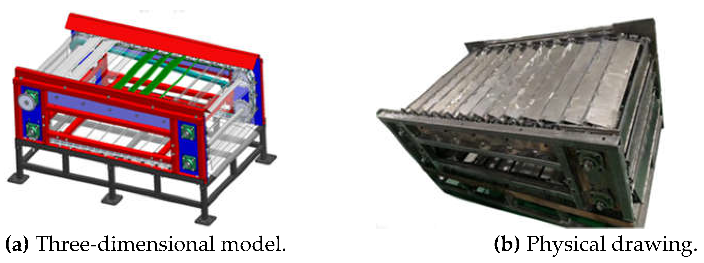
Figure 2.
Schematic diagram of potato grading principle. 1. Sprocket. 2. Chain. 3. Movable rotating plate. 4. Slide. 5. Potato.
Figure 2.
Schematic diagram of potato grading principle. 1. Sprocket. 2. Chain. 3. Movable rotating plate. 4. Slide. 5. Potato.
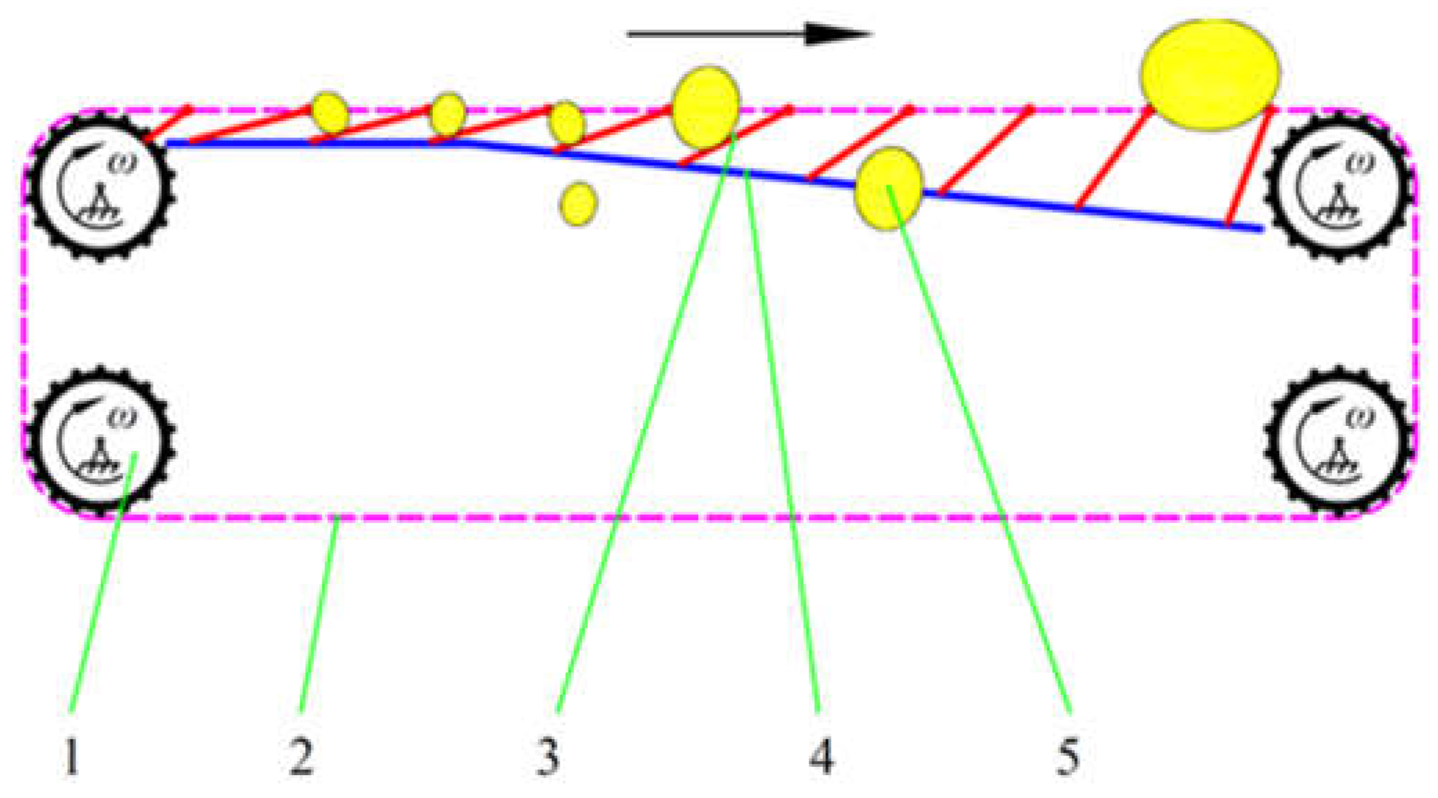
Figure 3.
Grading device frame.
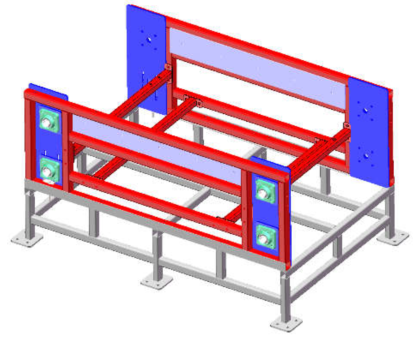
Figure 4.
Movable rotating plate 1. Rotating plate movable shaft. 2. Rotating plate. 3. Rotating plate friction shaft. 4. Bracket.
Figure 4.
Movable rotating plate 1. Rotating plate movable shaft. 2. Rotating plate. 3. Rotating plate friction shaft. 4. Bracket.
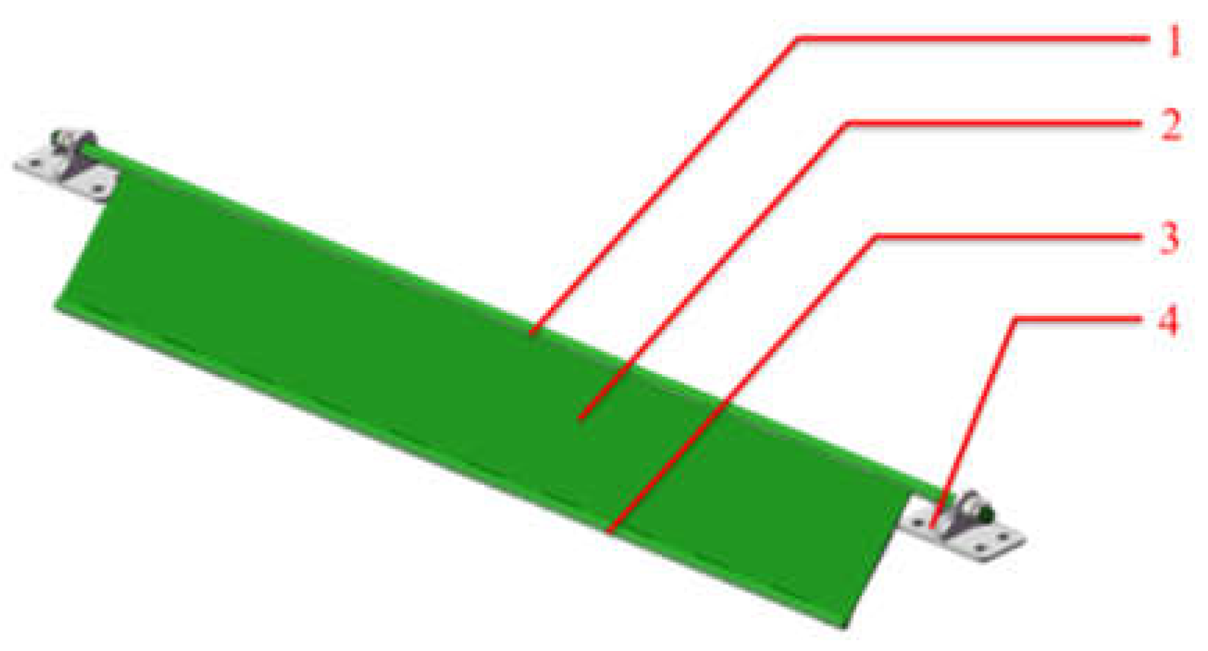
Figure 5.
Diagram of chain and movable rotating plate assembly.
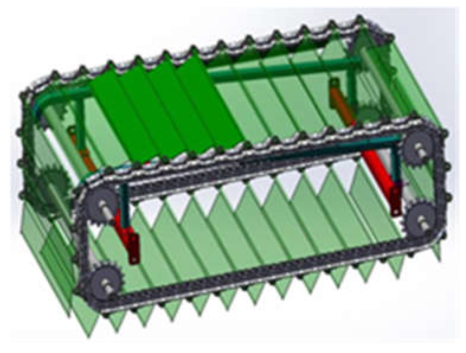
Figure 6.
A full load of grading device.
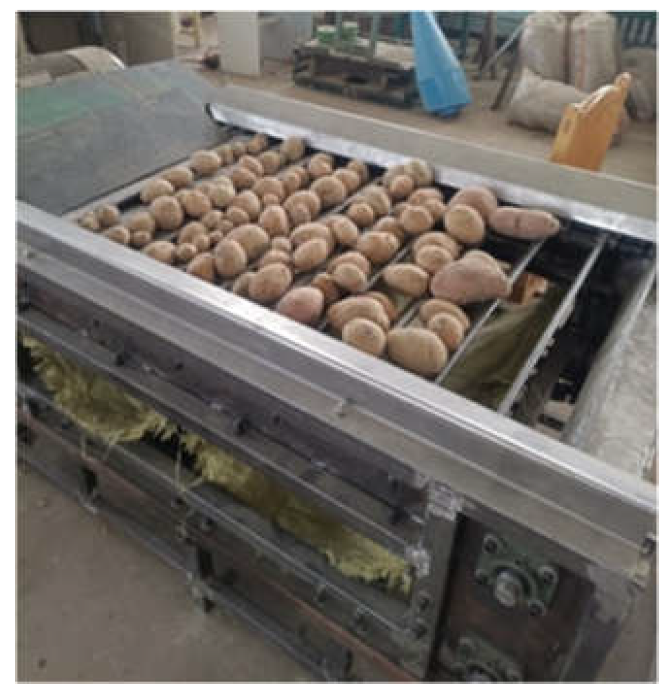
Figure 7.
Analysis diagram of the rack before optimization.
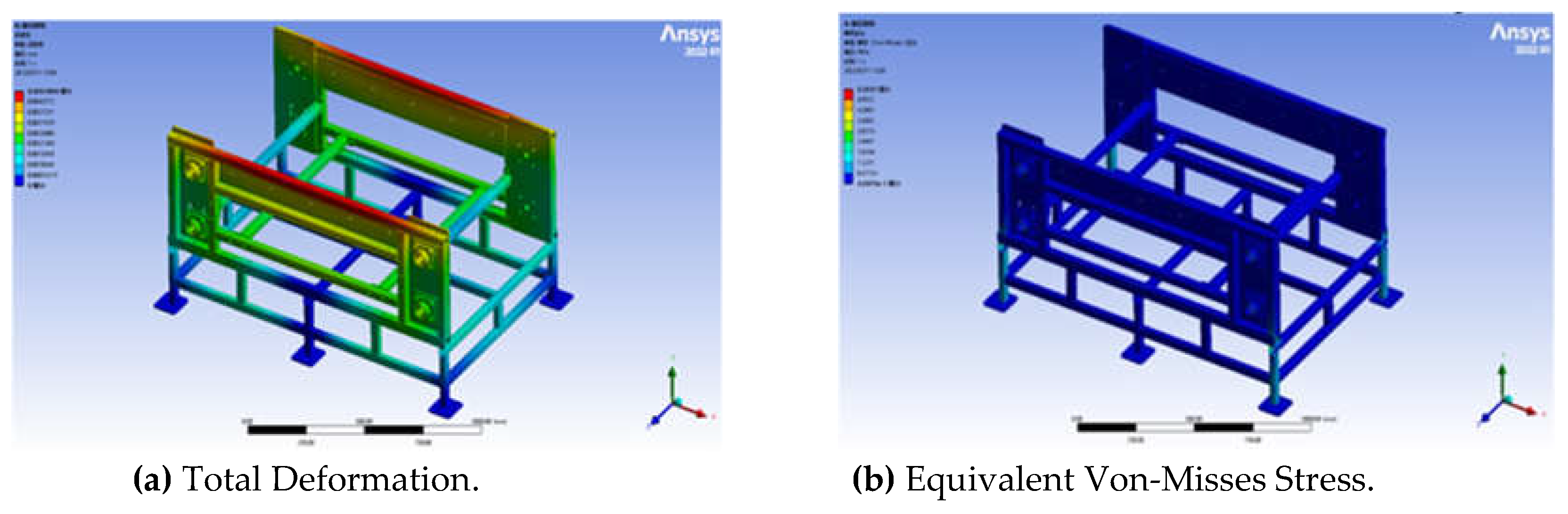
Figure 8.
Single movable rotating plate covered with potatoes.
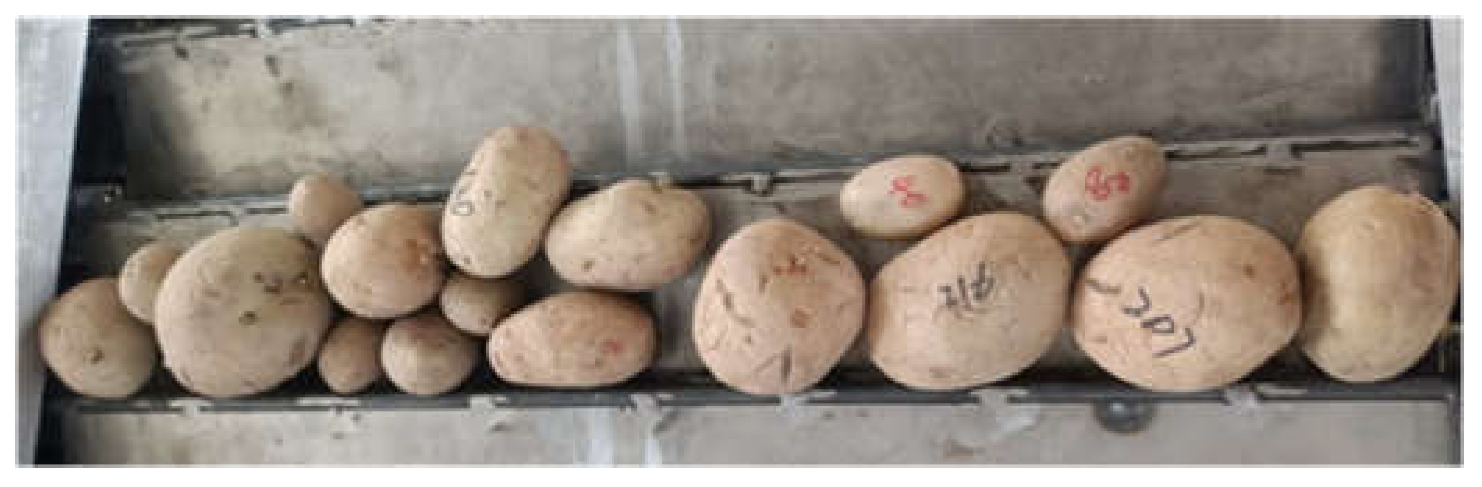
Figure 9.
Analysis clouds of the rotating plate before optimization.
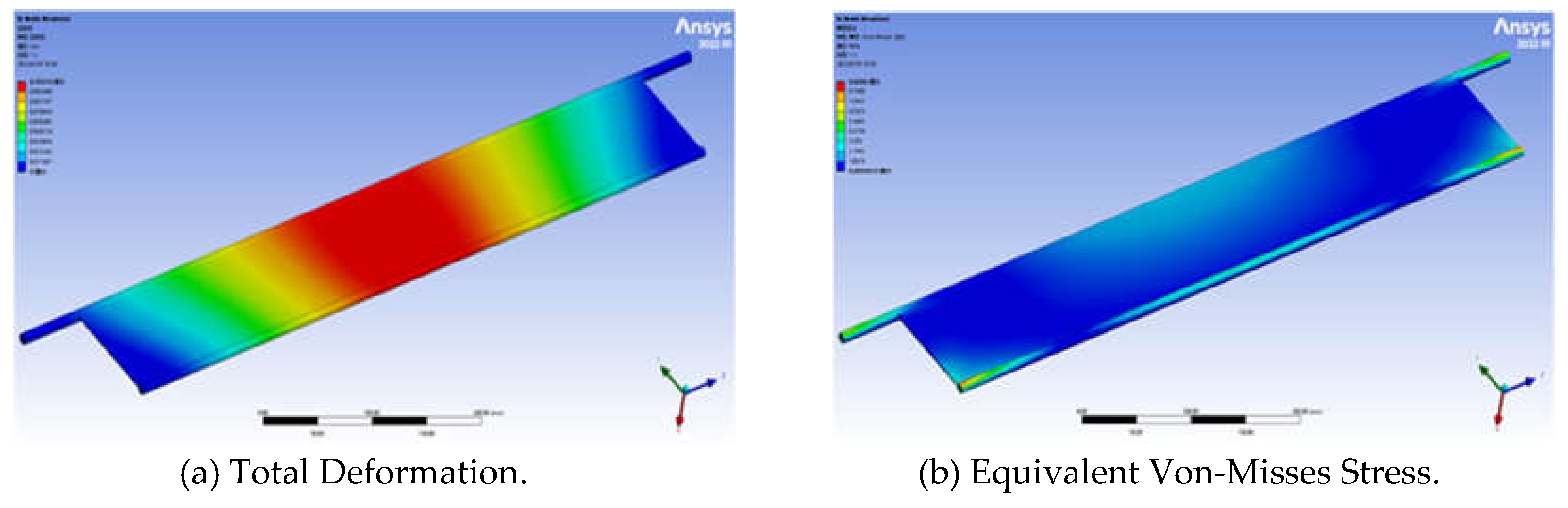
Figure 10.
Optimized body frame.
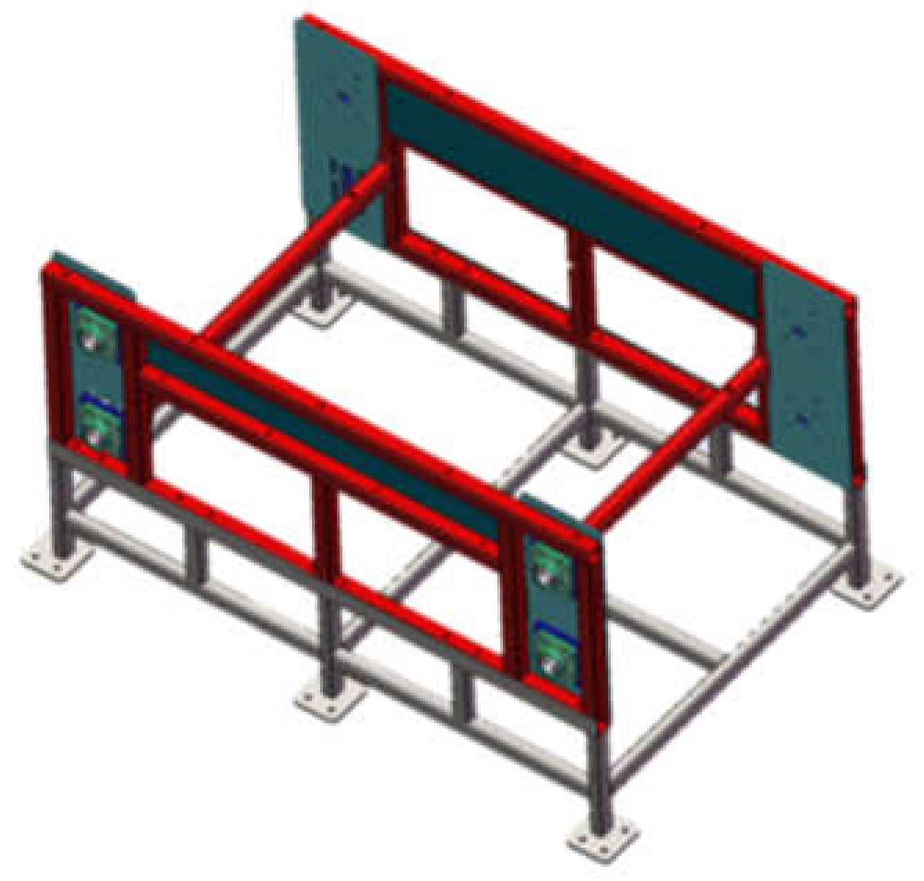
Figure 11.
Clouds of optimized body frame analysis results.
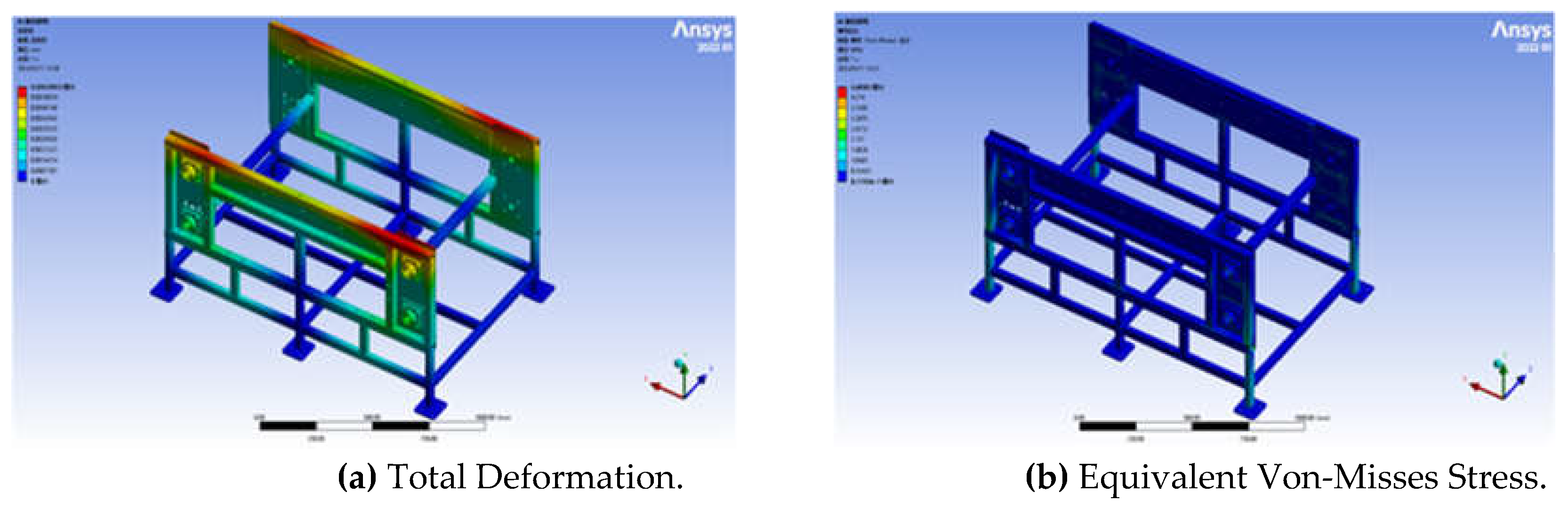
Figure 12.
Schematic diagram of the improved friction shaft of the rotating plate. 1. Slide rail. 2. Rotating plate movable shaft. 3. Bracket. 4. Rotating plate. 5. Rotating plate friction shaft 6. Chain.
Figure 12.
Schematic diagram of the improved friction shaft of the rotating plate. 1. Slide rail. 2. Rotating plate movable shaft. 3. Bracket. 4. Rotating plate. 5. Rotating plate friction shaft 6. Chain.
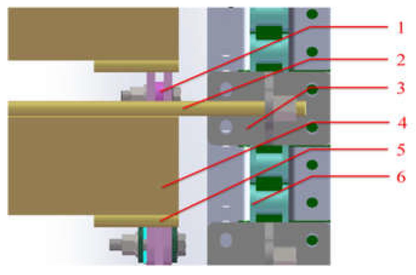
Figure 13.
Analysis clouds of the movable rotating plate before optimization.
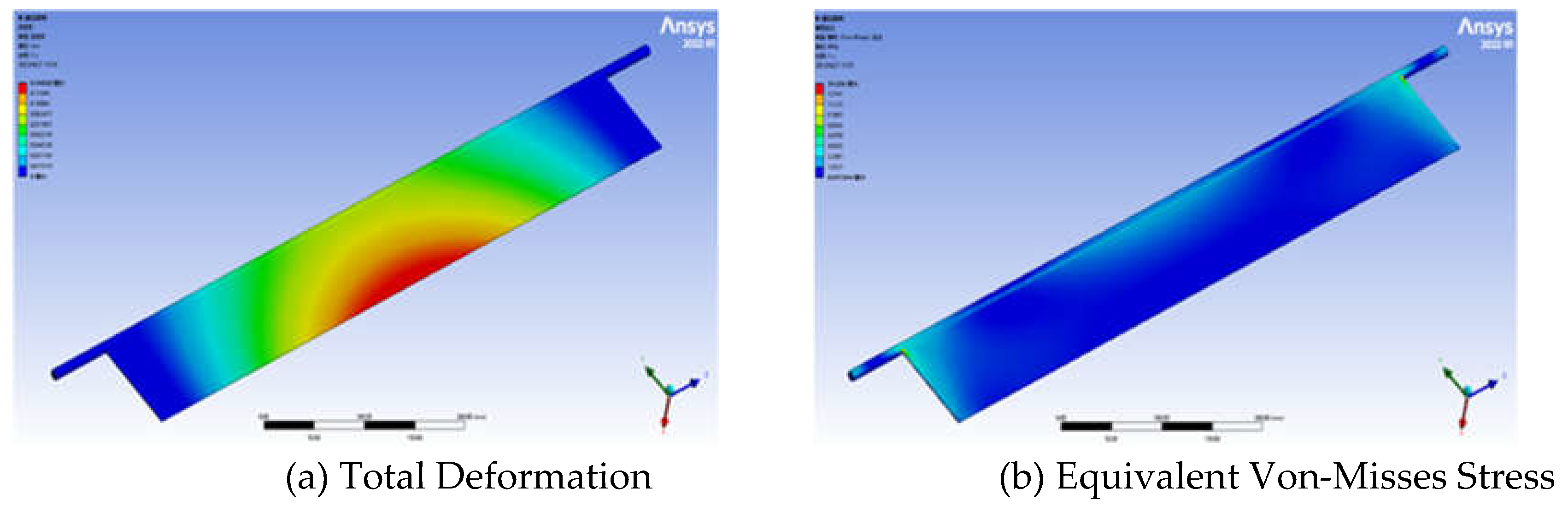
Figure 14.
Analysis clouds of the movable rotating plate after optimization.
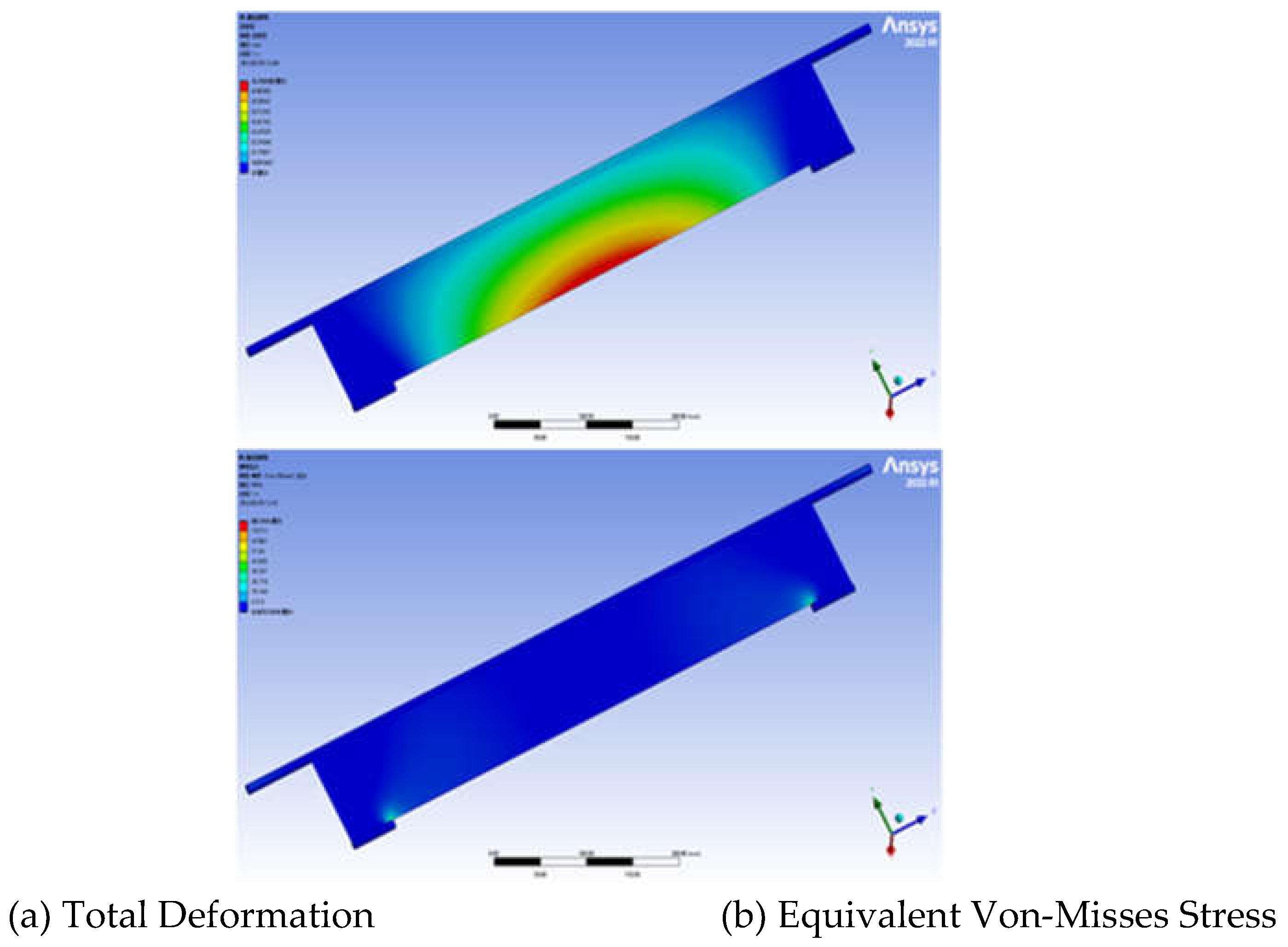

Table 1.
Material properties.
| Materials | Density(Kg/m3) | Young's Modulus/Pa | Poisson's Ratio | Yield Strength/Pa | Tangential Modulus/Pa |
|---|---|---|---|---|---|
| Q235 | 7850 | 2.12×10¹¹ | 0.288 | 2.35×10⁸ | 6.1×10⁹ |
Table 2.
Comparison of relevant parameters before and after frame optimization.
| Projects | Steel pipe wall thickness/mm | Side plate thickness/mm | The total mass of frame/kg |
|---|---|---|---|
| Before optimization | 4 | 8 | 157.82 |
| After optimization | 2 | 5 | 106.84 |
Table 3.
Design variable parameterization.
| Design variable name | Size / mm | Meaning of variables |
|---|---|---|
| DS_D1@ thin-stretch1 | 640 | the length of the rotating plate |
| DS_D2@ sketch2 | 95 | the width of the rotating plate |
| DS_D3@thin-stretch1 | 2 | the thickness of the rotating plate |
Table 4.
Raw optimization data.
| Serial number | P1 / mm | P2 / mm | P3 / mm | P4 / mm | P5 / MPa | P6 / kg |
|---|---|---|---|---|---|---|
| 1 | 610 | 95 | 1 | 0.335376 | 31.37097 | 0.924593 |
| 2 | 616 | 95 | 1 | 0.33314 | 31.54316 | 0.929073 |
| 3 | 620 | 95 | 1 | 0.338713 | 31.4189 | 0.93206 |
| 4 | 640 | 95 | 1 | 0.343188 | 33.55511 | 0.946994 |
| 5 | 610 | 98 | 1 | 0.353951 | 31.02046 | 0.938977 |
| 6 | 616 | 98 | 1 | 0.351401 | 31.18514 | 0.943598 |
| 7 | 620 | 98 | 1 | 0.357154 | 31.05804 | 0.946679 |
| 8 | 640 | 98 | 1 | 0.36119 | 33.17132 | 0.962085 |
| 9 | 610 | 100 | 1 | 0.366924 | 30.81309 | 0.948566 |
| 10 | 616 | 100 | 1 | 0.364175 | 30.97273 | 0.953282 |
| 11 | 620 | 100 | 1 | 0.370046 | 30.84402 | 0.956426 |
| 12 | 640 | 100 | 1 | 0.373807 | 32.94609 | 0.972146 |
| 13 | 610 | 95 | 1.2 | 0.247201 | 26.80225 | 1.01569 |
| 14 | 616 | 95 | 1.2 | 0.246619 | 26.99724 | 1.021066 |
| 15 | 620 | 95 | 1.2 | 0.250821 | 26.8091 | 1.024651 |
| 16 | 640 | 95 | 1.2 | 0.25723 | 28.43592 | 1.042571 |
| 17 | 610 | 98 | 1.2 | 0.258042 | 26.48829 | 1.032951 |
| 18 | 616 | 98 | 1.2 | 0.257254 | 26.67827 | 1.038497 |
| 19 | 620 | 98 | 1.2 | 0.261565 | 26.4883 | 1.042194 |
| 20 | 640 | 98 | 1.2 | 0.267701 | 28.09787 | 1.060681 |
| 21 | 610 | 100 | 1.2 | 0.265646 | 26.29697 | 1.044458 |
| 22 | 616 | 100 | 1.2 | 0.26473 | 26.48342 | 1.050117 |
| 23 | 620 | 100 | 1.2 | 0.269111 | 26.29202 | 1.05389 |
| 24 | 640 | 100 | 1.2 | 0.275079 | 27.8929 | 1.072754 |
| 25 | 610 | 95 | 1.5 | 0.178684 | 21.59502 | 1.152336 |
| 26 | 616 | 95 | 1.5 | 0.179551 | 21.69055 | 1.159057 |
| 27 | 620 | 95 | 1.5 | 0.1823 | 21.58057 | 1.163537 |
| 28 | 640 | 95 | 1.5 | 0.189913 | 22.48546 | 1.185938 |
| 29 | 610 | 98 | 1.5 | 0.184138 | 21.33209 | 1.173912 |
| 30 | 616 | 98 | 1.5 | 0.184898 | 21.4249 | 1.180844 |
| 31 | 620 | 98 | 1.5 | 0.187684 | 21.31408 | 1.185466 |
| 32 | 640 | 98 | 1.5 | 0.195152 | 22.20793 | 1.208575 |
| 33 | 610 | 100 | 1.5 | 0.188006 | 21.16695 | 1.188296 |
| 34 | 616 | 100 | 1.5 | 0.1887 | 21.25752 | 1.19537 |
| 35 | 620 | 100 | 1.5 | 0.19151 | 21.14581 | 1.200086 |
| 36 | 640 | 100 | 1.5 | 0.198891 | 22.03336 | 1.223666 |
| 37 | 610 | 95 | 1.8 | 0.140836 | 17.79926 | 1.288982 |
| 38 | 616 | 95 | 1.8 | 0.142329 | 17.86102 | 1.297047 |
| 39 | 620 | 95 | 1.8 | 0.14429 | 17.78071 | 1.302423 |
| 40 | 640 | 95 | 1.8 | 0.15203 | 18.18255 | 1.329304 |
| 41 | 610 | 98 | 1.8 | 0.143799 | 17.57471 | 1.314873 |
| 42 | 616 | 98 | 1.8 | 0.145232 | 17.63877 | 1.323192 |
| 43 | 620 | 98 | 1.8 | 0.147198 | 17.55431 | 1.328738 |
| 44 | 640 | 98 | 1.8 | 0.154848 | 17.94952 | 1.356468 |
| 45 | 610 | 100 | 1.8 | 0.145937 | 17.43167 | 1.332134 |
| 46 | 616 | 100 | 1.8 | 0.147335 | 17.49638 | 1.340623 |
| 47 | 620 | 100 | 1.8 | 0.149304 | 17.40931 | 1.346282 |
| 48 | 640 | 100 | 1.8 | 0.156902 | 17.80011 | 1.374578 |
| 49 | 610 | 95 | 2 | 0.129303 | 14.27097 | 1.38008 |
| 50 | 616 | 95 | 2 | 0.131227 | 14.31895 | 1.38904 |
| 51 | 620 | 95 | 2 | 0.132632 | 14.2965 | 1.395014 |
| 52 | 640 | 95 | 2 | 0.140215 | 14.55594 | 1.424882 |
| 53 | 610 | 98 | 2 | 0.131863 | 14.06587 | 1.408847 |
| 54 | 616 | 98 | 2 | 0.133774 | 14.11403 | 1.418091 |
| 55 | 620 | 98 | 2 | 0.135171 | 14.08991 | 1.424253 |
| 56 | 640 | 98 | 2 | 0.142727 | 14.34426 | 1.455064 |
| 57 | 610 | 100 | 2 | 0.133604 | 13.93621 | 1.428026 |
| 58 | 616 | 100 | 2 | 0.135506 | 13.9844 | 1.437458 |
| 59 | 620 | 100 | 2 | 0.1369 | 13.95889 | 1.443746 |
| 60 | 640 | 100 | 2 | 0.14444 | 14.20926 | 1.475186 |
Table 5.
Optimized design points.
| Candidate points | P1 / mm | P2 / mm | P3 / mm | P4 / mm | P5 / MPa | P6 / kg |
|---|---|---|---|---|---|---|
| 1 | 610 | 95 | 1.2 | 0.2472 | 26.802 | 1.0157 |
| 2 | 616 | 95 | 1.2 | 0.24662 | 26.997 | 1.0211 |
| 3 | 620 | 95 | 1.2 | 0.25082 | 26.809 | 1.0247 |
Table 6.
Comparison of the parameters before and after the optimization of the rotating plate.
| Projects | P1 / mm | P2 / mm | P3 / mm | P4 / mm | P5 / MPa | P6 / kg |
|---|---|---|---|---|---|---|
| Before optimization | 640 | 95 | 2 | 0.140215 | 14.55594 | 1.424882 |
| After optimization | 610 | 95 | 1.2 | 0.2472 | 26.802 | 1.0157 |
Table 7.
Comparison of static Analysis of frame and movable rotating plate before and after optimization.
Table 7.
Comparison of static Analysis of frame and movable rotating plate before and after optimization.
| Optimization Project | Mass / kg | Total deformation / mm | Equivalent Stress / MPa | |
|---|---|---|---|---|
| Body frame | Before optimization | 157.82 | 0.0047894 | 5.5037 |
| After optimization | 106.84 | 0.0063963 | 4.8083 | |
| Movable rotating plate | Before optimization | 1.7449 | 0.10513 | 9.8396 |
| After optimization | 1.0657 | 0.76938 | 86.144 | |
Disclaimer/Publisher’s Note: The statements, opinions and data contained in all publications are solely those of the individual author(s) and contributor(s) and not of MDPI and/or the editor(s). MDPI and/or the editor(s) disclaim responsibility for any injury to people or property resulting from any ideas, methods, instructions or products referred to in the content. |
© 2023 by the authors. Licensee MDPI, Basel, Switzerland. This article is an open access article distributed under the terms and conditions of the Creative Commons Attribution (CC BY) license (http://creativecommons.org/licenses/by/4.0/).
Copyright: This open access article is published under a Creative Commons CC BY 4.0 license, which permit the free download, distribution, and reuse, provided that the author and preprint are cited in any reuse.


