Submitted:
07 June 2023
Posted:
08 June 2023
You are already at the latest version
Abstract
A wideband antenna with excellent efficiency is the most important requirement of wireless communication. There are many ways to improve the antenna bandwidth, such as using a low permittivity substrate, increasing the substrate thickness, and using different shapes of radiating patches. However, this cannot achieve wideband. This problem can be solved by using a metamaterial-based microstrip antenna that can achieve wideband. The proposed patch antenna has a metamaterial unit cell loaded on the top patch and on the bottom ground plane. The top unit cell, which consists of a square loop with Complementary Split Ring Resonator (CSRR) and the bottom unit cell, which is a Square Shaped Cross-Slot (SSCS), is loaded on the patch and ground. The objective is to achieve a compact metamaterial-loaded antenna with enhanced radiation characteristics and to design a metamaterial antenna for wideband applications. The wideband and high gain features of the proposed antenna make it suitable for 5G NR FR1 and Wi-Fi 6E applications.
Keywords:
Metamaterial
; wideband
; Microstrip patch
; unit cell
; Wi-Fi 6E
1. INTRODUCTION
Antennas play a crucial role in wireless communication systems as they facilitate the transmission and reception of signals through the conversion of electromagnetic waves. These devices operate based on Maxwell's equations, which fully characterize their transmitting and receiving functions.
2. LITERATURE REVIEW
Various research studies have been conducted in the field of wideband antennas and metamaterials. Neeshu and Tiwary proposed a microstrip patch antenna loaded with metamaterial, achieving a wideband radiation from 2.88 to 14 GHz. Wu et al. developed a self-shape fusion algorithm to enhance the bandwidth of a printed microstrip wide-slot rotating antenna. Hossain et al. introduced a compact flexible planar monopole antenna integrated with a Negative Index Nonagonal-CSRR Meta Unit Cell Array (MTMUCA) for ultra-wideband applications. Dey, Mondal, and Sarkar designed a circularly polarized antenna using Complementary Split Ring Resonators (CSRRs). Rao and Basarkod presented a complementary slot split ring resonator truncated arc antenna with enhanced performance.
3. PROPOSED WORK
This section is subdivided into two parts.
3.1. Strip line feeding
3.2 Geometry of designed antenna
3.1. Strip line feeding
This feeding technique involves directly attaching a narrower conductive strip to the edge of the microstrip patch. One advantage of this arrangement is that the feed can be etched on the same substrate, resulting in a planar structure. This feeding scheme facilitates easy fabrication and offers simplicity in housing and impedance matching. However, using a thicker dielectric substrate leads to an increase in surface wave spurious feed radiation, which ultimately restricts the antenna's bandwidth
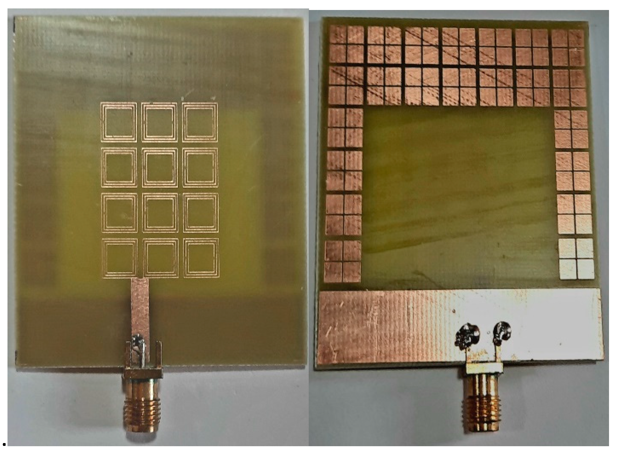
Figure 1.
Fabricated antenna top & bottom view.
3.2. Geometry of Designed Antenna
Figure 2.
Top View.
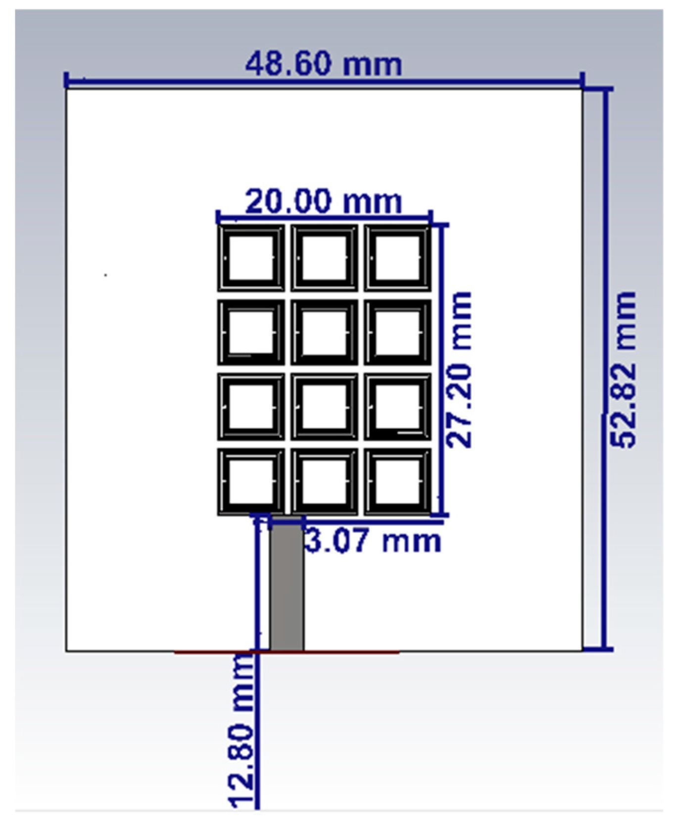
Figure 3.
Bottom View.
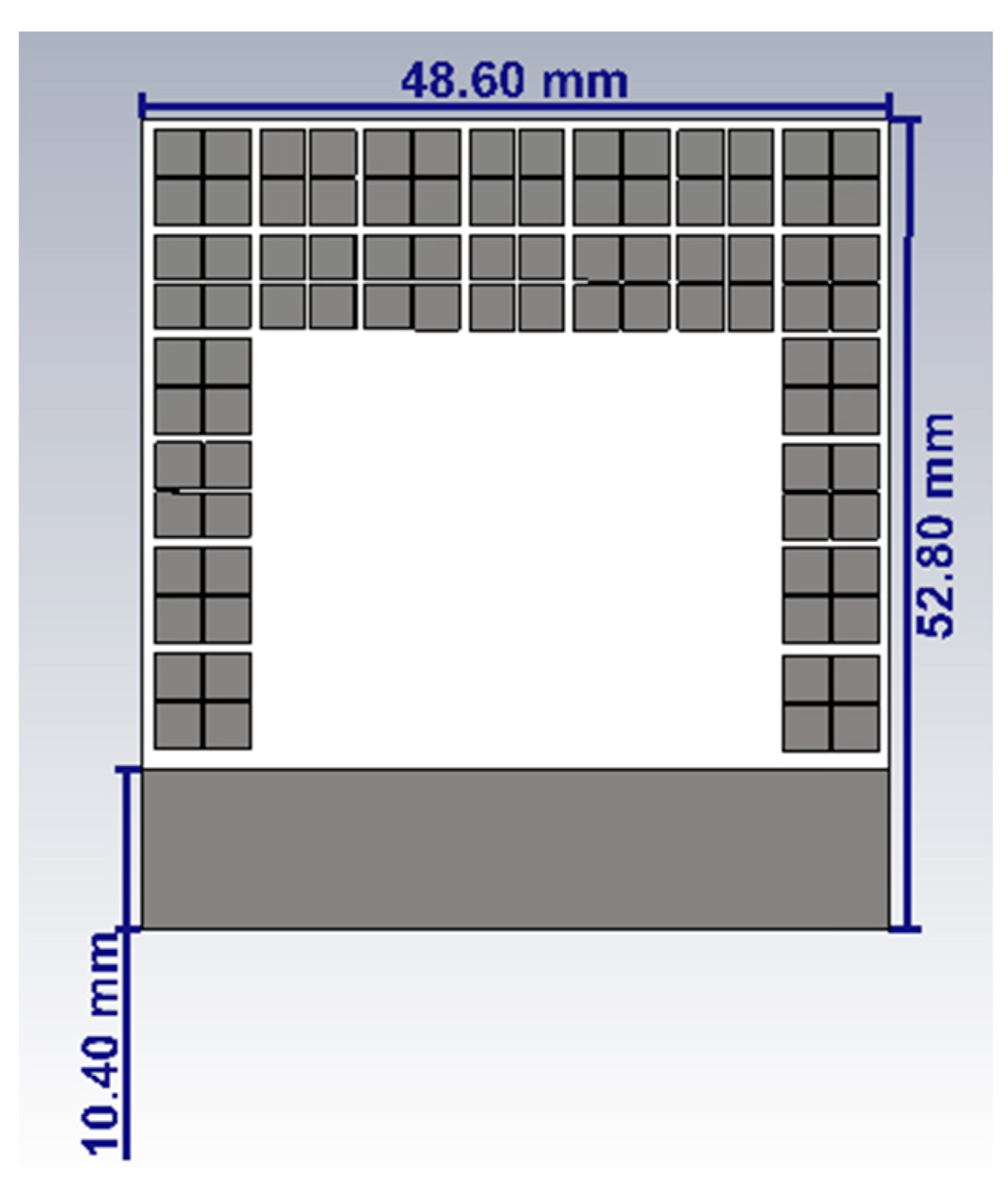
Figure 4.
Top unit cell.
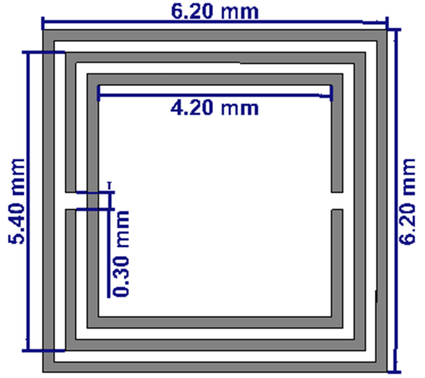
Figure 5.
Bottom unit cell.
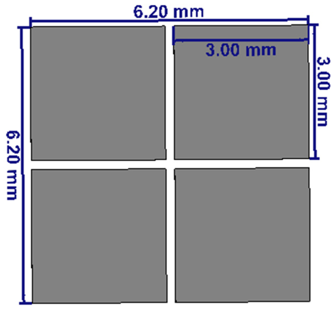
The dimensions of the proposed unit cell as shown Fig-4, are L = 6.20mm, W = 6.20mm which gives a wide response. Three square rings are designed in each unit cell. The difference in size of each square ring is 0.8mm. The top unit cell consists of a square loop with Complementary Split Ring Resonator (CSRR). The bottom unit cell is square-shaped with a cross-slot (SSCS) is loaded on the patch and ground respectively.
A metamaterial loaded planar patch antenna is proposed and shown in Figure 2 & 3 has a top view and bottom view, respectively. The FR4 substrate of relative permittivity ℇr = 4.4, loss tangent 0.025, and thickness (h) 1.6 mm is used to fabricate the proposed antenna of size 48.6 mm × 52.8 mm. This antenna comprises loading of CSRR and SSCS in the patch and ground plane, respectively. The partial ground plane of length 12.8 mm underneath the input port of the antenna. Top patch of antenna is loaded with 4 × 3 CSRR unit cells and to improve the radiation efficiency, a window is etched on the backside of patch antenna. The optimized dimensions of antenna are W = 48.6 mm, L = 52.8 mm,
4. RESULTS AND DISCUSSION
4.1. Return loss
Return loss is a parameter that is interconnected with both the Standing Wave Ratio (SWR) and reflection coefficient. When the return loss increases, the SWR decreases. Return loss serves as an indicator of the level of matching between equipment or transmission lines. A high return loss signifies a good match, which is desirable as it results in lower insertion loss.
Figure 6.
Return loss.
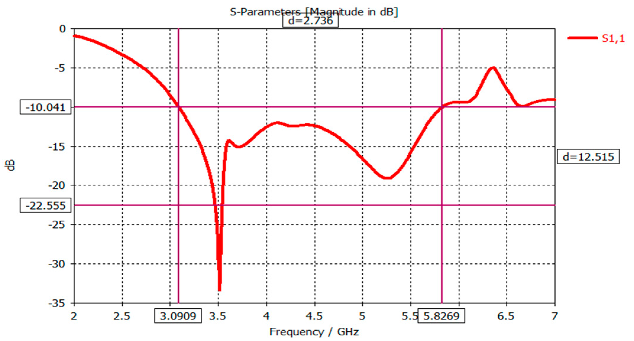
Figure 6 shows us the simulated results shows that, the antenna operates at 7.5 GHz with the return loss of -18.519 respectively.
4.2. Gain
An isotropic antenna radiates evenly in all directions. An isotropic radiator is considered 100% efficient. The gain of an actual antenna increases the power density in the direction of the peak radiation.
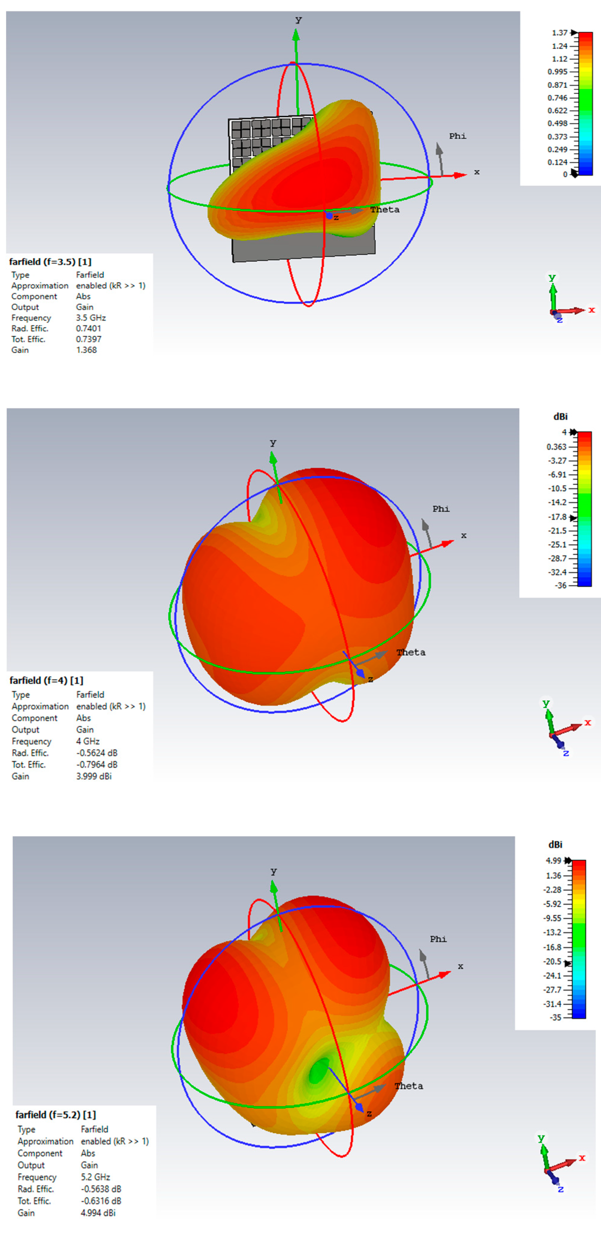
Figure 7.
Gain when f = 3.5 GHz, 4 GHz & 5.2 GHz respectively.
4.3. Directivity
Directivity measures the power density radiated by an antenna in the direction of its strongest emission, compared to the power density radiated by an ideal isotropic radiator emitting the same total power.
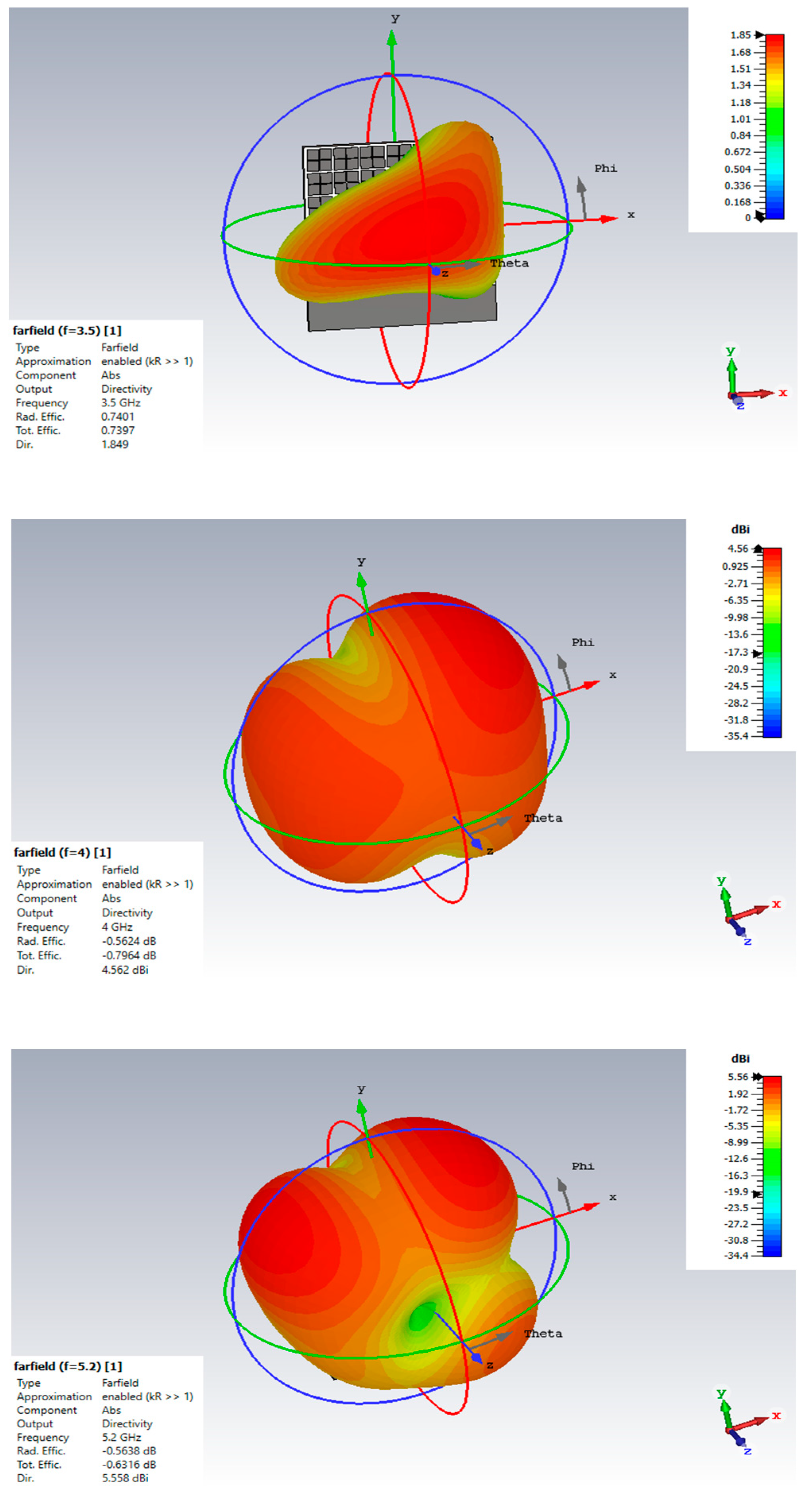
Figure 8.
Directivity when f = 3.5 GHz, 4 GHz & 5.2 GHz respectively.
4.4. VSWR Measurement
VSWR is a function of the reflection coefficient, which describes the power reflected from the antenna.
Figure 9.
VSWR Measurement.
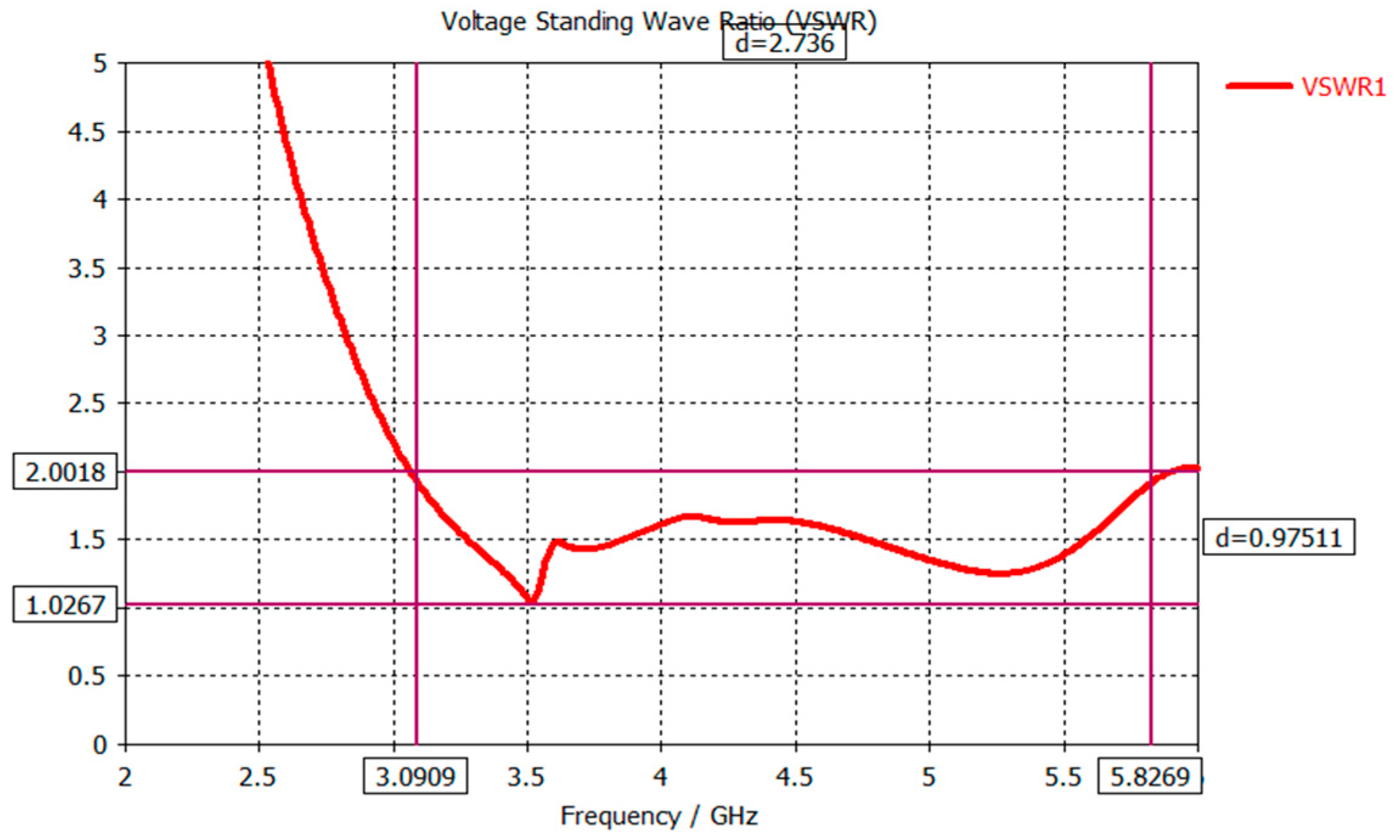
Figure 9 depicts the antenna yields minimum VSWR value of 1.269.

Table 1.
Gain, Directivity & Efficiency when f = 3.5 GHz, 4 GHz & 5.2 GHz respectively.
| FREQUENCY | GAIN | DIRECTIVITY |
| 3.5 GHz | 1.319 dBi | 2.613 dBi |
| 4 GHz | 4.013 dBi | 4.578 dBi |
| 5.2 GHz | 5.021 dBi | 5.585 dBi |
After analyzing the data presented in Table 1, it can be discerned that there is a discernible pattern in which gain and directivity show an upward trend with increasing frequency, implying a positive correlation between these parameters and the varying frequencies under consideration
5. CONCLUSION
In conclusion, the need for wideband antennas with excellent efficiency in wireless communication systems has been addressed. While previous approaches to enhance antenna bandwidth have limitations, the proposed metamaterial-loaded antenna demonstrates wideband performance and high gain characteristics. Consequently, it is well-suited for applications in 5G NR FR1 and Wi-Fi 6E systems, where wideband communication is critical.
References
- KM Neeshu and Anjini Kumar Tiwary, “Metamaterial Loaded Antenna with Improved Efficiency and Gain for Wideband Application” - IETE Journal of Research, Dec 2020.
- Aiting Wu, Furan Zhu, Pengquan Zhang, Zhonghai Zhang, and Boran Guan, “Bandwidth Enhancement of a Microstrip-Line-Fed Printed Rotated Wide-Slot Antenna Based on Self-Shape Blending Algorithm - Hindawi”, Aug 2021.
- Soumik Dey, Santanu Mondal, and Partha P. Sarkar, “High gain and frequency reconfigurable copper and liquid metamaterial tooth based microstrip patch antenna”, Feb 2019.
- Kabir Hossain, Thennarasan Sabapathy, Muzammil Jusoh, Mahmoud A. Abdelghany, Ping Jack Soh, Mohamed Nasrun Osman, Mohd Najib Mohd Yasin, Hasliza A. Rahim and Samir Salem Al-Bawri,” A Negative Index Nonagonal CSRR Metamaterial-Based Compact Flexible Planar Monopole Antenna for Ultrawideband Applications Using Viscose-Wool Felt”, Aug 2021.
- Maroli S. Rao and Prabhugoud I. Basarkod, “A Novel Complementary Slotted Split Ring Resonator Loaded Truncated Arc Patch Antenna with Enhanced Performance - Progress In Electromagnetics Research”, May 2020.
- Sunil P. Lavadiya, Shobhit K. Patel, Rayisyan Maria,” High gain and frequency reconfigurable copper and liquid metamaterial tooth based microstrip patch antenna”, May 2021.
- Khaled Aliqab, Sunil Lavadiya, Meshari Alsharari, Ammar Armghan, Malek G. Daher and Shobhit K. Patel,” Design and Fabrication of a Low-Cost, Multiband and High Gain Square Tooth-Enabled Metamaterial Superstrate Microstrip Patch Antenna”,Jan 2023.
- Asghar Bakhtiari,” Investigation of Enhanced Gain Miniaturized Patch Antenna Using Near Zero Index Metamaterial Structure Characteristics”, Jul 2019.
- M. Z. Mahmud, M. T. Islam, and M. Samsuzzaman, “A high performance UWB antenna design for microwave imaging system,” Microw. Opt. Technol. Lett., Vol. 58, pp. 1824–31,2016. [CrossRef]
- Saleem, M. Bilal, T. Shabbir, and M. F. Shafique, “An FSS- employed UWB antenna system for high gain portable devices,” Microw. Opt. Technol. Lett., Vol. 61, pp. 1404–10, 2019. [CrossRef]
- A. Bakhtiari, “Investigation of enhanced gain miniaturized patch antenna using near zero index metamaterial structure characteristics,” IETE. J. Res., Vol. 65, pp. 1–8, 2019. [CrossRef]
- Zhu and G. V. Eleftheriades, “A compact transmission-line metamaterial antenna with extended bandwidth,” IEEE Antennas Wireless Propag. Lett, Vol. 8, pp. 295–8, 2009. [CrossRef]
- H. Xiong, J. S. Hong, Z. Q. Yi, and J. D. Lin, “Compact ultra-wideband microstrip antenna with metamaterials,” Chin. Phys. Lett., Vol. 29, pp. 102–14, 2012. [CrossRef]
- A. Gupta and R. K. Chaudhary, “A compact CPW-fed wideband metamaterial antenna with EBG loading,” Microw. Opt. Technol. Lett., Vol. 57, pp. 2632–6, 2015. [CrossRef]
- M. Z. Mahmud, M. T. Islam, and M. Samsuzzaman, “A high performance UWB antenna design for microwave imaging system,” Microw. Opt. Technol. Lett., Vol. 58, pp. 1824–31, 2016. [CrossRef]
Disclaimer/Publisher’s Note: The statements, opinions and data contained in all publications are solely those of the individual author(s) and contributor(s) and not of MDPI and/or the editor(s). MDPI and/or the editor(s) disclaim responsibility for any injury to people or property resulting from any ideas, methods, instructions or products referred to in the content. |
© 2023 by the authors. Licensee MDPI, Basel, Switzerland. This article is an open access article distributed under the terms and conditions of the Creative Commons Attribution (CC BY) license (http://creativecommons.org/licenses/by/4.0/).
Copyright: This open access article is published under a Creative Commons CC BY 4.0 license, which permit the free download, distribution, and reuse, provided that the author and preprint are cited in any reuse.


