
Submitted:
04 June 2023
Posted:
05 June 2023
You are already at the latest version
Abstract
Epsilon-near-zero nanoantennas can be used to tune the far-field radiation pattern due to their exceptionally large intensity-dependent refractive index. Here, we propose hybrid optical antenna based on indium tin oxide (ITO) to optically tune the deflection of radiation. In particular, a hybrid structure antenna of ITO and dielectric material, which makes the deflection angle changes 17 ∘ as incident intensities increases. Finally, the array of ITO or hybrid nanodisks can enhance the unidirectionality to be needle-like, with the angular beam width α< 8∘ of main lobe. The deflection angle of radiation pattern response with needle-like lobe pave the way for further studies and applications in beam steering and optical modulation where dynamic control of the nanoantennas is highly desirable.
Keywords:
Tunable deflection
; epsilon-near-zero
; metamaterial.
0. Introduction
Optical antennas have drawn much attention in the field of photonics due to their potential applications. The role of the antenna is to receive and transmit signals. Different from radio frequency (RF) microwave antennas, optical antennas manipulate and control optical radiation on the subwavelength scale.The optical responses of antennas are predominantly influenced by the geometry and surrounding environment. Traditionally, a direct method to achieve tuning effect could be realized by reshaping the geometry of antennas, such as laser ablating [1]. However, this method is not reversible. In addition, various approaches for dynamical manipulation of the beam steering and reversible tuning can be achieved via optical [2], external input [3], electrical [4], chemical [5], magneto-optical [6,7] and even mechanical tuning [8]. In comparison, optical tuning offers additional advantages such as fast response time, reversible processes. The intensity of the incident light, decides the induced electric and magnetic multipole moments [9]. Several antenna structures have been proposed to increase the field enhancement factor of the antenna and to adjust its resonance characteristics, aiming to provide an effective way to process optical information, adjust the spectrum or far field radiation response [10,11]. The study of radiation control of optical antennas is of great significance in the research fields of ultra-diffraction limit imaging, new optical probes, and propagation control of nanoscale optical information [12,13,14,15,16]. To control the far-field radiation of an optical antenna, its optical properties must be dynamically modulated. In recent years, indium tin oxide (ITO) as an epsilon-near-zero (ENZ) material has been reported. ITO can obtain an intensity-dependent refractive index at ultra-high speed in the spectral region where the real part of the permittivity is small. The ITO inspire new concepts for beam steering. This change of refractive index is reversible and its response time is femtoseconds experimentally [17].
We conducted a theoretical investigation into the modulation of the far-field radiation of the optical nano-antenna utilizing ENZ material. Initially, we examined the radiation pattern of a single ITO nanoparticle and demonstrated that it can be altered by increasing the incident intensity. To further enhance the control over the deflection angle of the radiation pattern, we propose a hybrid structure comprising ITO and dielectric nanodisk. This hybrid structure exploits the remarkable Kerr effect of ENZ materials. Additionally, we explored the directional scattering properties of nanodisks arranged in a one-dimensional (1D) chain, observing how the intensity of the laser can influence these properties.
1. Materials and Methods
The proposed structure, consisting of three-dimensional (3D) ITO disk with height (H) of 400 nm and diameter (D) of 600 nm, as schematically shown in the inset of Figure 1a. The nonlinear material, composed of ITO, is illuminated by a plane wave with an electric field , where is the wavenumber, is the angular frequency, denotes the amplitude of incident field, and c.c. signifies the complex conjugate. is the free-space intensity of the incident plane wave. The intensity-dependent refractive index of ITO, denoted as , is approximately equal to the square root of the nonlinear permittivity , where is given by [18,19]
Here, , , and are the third-order, fifth-order, and seventh-order nonlinear susceptibilities (refer to Table 1 in Ref. [19]) of ITO, respectively. The degeneracy factors are given by [18]. The electric field inside the ITO is denoted by . The real part of the dielectric constant of ITO is zero at 1240 nm that is the ENZ wavelength [14,19]. As per the relationship between refractive index and permittivity (), a change of in the permittivity leads to a change of . Consequently, ITO exhibits strong nonlinear optical properties when the permittivity becomes small. Figure 1a illustrates the intensity-dependent refractive index of a single ITO at [14,19]. The change in the real part of the refractive index with intensity is approximately 0.72, while the linear refractive index is 0.4.
The optical response of radiation pattern can be described using the multipole expansion of the induced displacement current [9,20]. The excited multipole can be obtained by the induced nonlinear displacement current . The multipole expansion, introduced by [9,20], is given as follows:
where , , , , and are the electric dipole (ED), magnetic dipole (MD), electric quadrupole (EQ), and magnetic quadrupole (MQ) multipole moments, respectively. is the nth spherical Bessel function. The total scattering cross section can be calculated using the following expression [9,20]
which is the contribution of each multipole moment (marked ’total’ in Figure 1c and Figure 2c). The far field corresponding to the radiation pattern () in space is
Here, r, , and represent the spherical coordinates. k is the wavenumber, c is the speed of light.
2. Results
We utilized the finite difference time domain (FDTD) to analyze the two-dimensional (2D) far-field radiation patterns at and , respectively. For the simulations, periodic boundary conditions are employed along the x and y axes, while perfectly matched layer (PMLs) were used along the z axis. A single plane wave source at 1240 nm was employed for normal incidence. To ensure accurate results, the mesh size is optimized after conducting a converging test. The corresponding three-dimensional (3D) radiation pattern are presented in Figure 1(b1,b2). The changes observed in the scattering cross section in Figure 1c can be attributed to the contribution of different multipole moments, as described by Eq. (2). At an incident intensity of , the main lobe width of radiation pattern slightly increases compared to . This variation is due to the different electric field distributions associated with distinct local electromagnetic modes within the ITO structure, which can be calculated using an iteration method. The refractive index, ) [see Figure 2d], has varying effects on each multipole moment. The enhanced forward scattering is achieved when the oscillating dipole and quadrupole modes are in phase [21]. Therefore, the induced ED, MD, and MQ moments (normalized to ) interfere constructively (destructively) in the forward direction. Consequently, the antenna exhibits a nearly unidirectional radiation pattern with small backscattering, known as generalized Kerker effect [21]. Hence, the observed slight differences in the backward radiation pattern are entirely due to the varying induced electric and magnetic multipole moments calculated by Eq. (2) [see Figure 1c]. Importantly, the scattering cross section calculated using FDTD demonstrate excellent agreement with the results obtained from the multipole expansion described in Eq. (3). The findings highlight the advantages capabilities of an ENZ-based antenna in controlling the radiation pattern(). Here, is calculated by Eq. (4). When both electric/magnetic dipole and quadrupole coexist, the so-called generalized Kerker condition can be expressed as
The phase can be obtained using arg(), arg(), arg( ) and arg( ). When dipole and quadrupole oscillate in phase (i.e., “+”), they constructively interference with each other and the resulted scattering pattern will be strongly enhanced along the forward direction. As the intensity increases, ED and MD almost oscillate in phase (red solid line), which satisfy the Kerker effect. Likewise, EQ and MQ nearly meet the generalized Kerker effect. Since the phase difference between the dipole and the quadrupole modes (red dashed line) is about 0.4 [see Figure 1d], the backscattering is maximally suppressed (see Figure 1(b1,b2)). Therefore, the far-field radiation of this nanoantenna exhibits almost unidirectionally forward scattering. Different local electromagnetic modes have different electric field distributions, and the distribution in the ITO is not uniform which can be calculated using method. The refractive index [see Figure 1e] will eventually have different effects on each multipole.
The utilization of high-refractive-index dielectric materials with low loss in antenna design results in a strong electromagnetic response and a significant large scattering cross section [11,22]. To further enhance control over the scattering properties of ITO antennas, we propose a nonlinear antenna composed of both ENZ and lossless dielectric materials. By incorporating a high-refractive-index material (=1.8) and ITO nanodisks, a hybrid antenna is created to dynamically adjust the deflection and beamwidth angle of the radiation pattern. The optimized configuration consists of ITO ( nm, nm) and dieletric material ( nm, nm) with a separation distance of 100 nm, as depicted in Figure 2a. The dispersion angle in the plane, denoted as , is illustrated in Figure 2b. When the incident intensity gradually increases from to , the radiation main lobe undergoes noticeable deflection, and the deflection angle is . The corresponding 3D radiation pattern calculated using Eq. (4) are presented in Figure 2(b1,b2). The varying intensities lead to difference in the multipole moments, resulting in intensity-dependent magneto-electric coupling [see Figure 2c]. Specifically, as the intensity increases, the contribution of the ED moment gradually increases, while the EQ moment decreases. The MD and MQ remain constant in the scattering cross section. The induced ED, MD, EQ and MQ moments interfere constructively (destructively), thereby, altering the radiation pattern, as observed in Figure 2b. In comparision with other methods of adjusting the angle size [23], our approach offers the advantage of achieving the deflection angle solely by changing the light intensity, with a maximum change of in the deflection angle. Additionally, in Figure 2d, we present the real part of the refractive index of the hybrid antenna in -plane when . The refractive index is position-dependent, influenced by the nonuniform electric field distribution within the antenna and the coupling effect between ITO and linear dielectric material.
Figure 3a schematically illustrate a linear chain of ITO disks aligned along the x-axis. The normalized radiation pattern for different quantities of ITO disks are presented in Figure 3b,c at and , respectively. As the number of ITO disks increases, the width of the main lobe in radiation decreases decreases. This trend is observed in both cases. Specifically, the angular beamwidth of the main lobe, denoted as , decrease from to . This reduction indicates reduced energy leakage in the undesired directions, attributed to the constructive interference among dominant multipolar moments. The sharp angular beamwidth of the main lobe signifies improved scattering directivity. Further increasing the number of ITO disks does not yield significant changes in the radiation pattern. The main lobe progressively achieves a high level of directivity, with ( approaching ) as more pairs of nanodisks are added. Consequently, the scattering cross section increases with the the number of ITO disks, as demonstrated in Figure 3d.
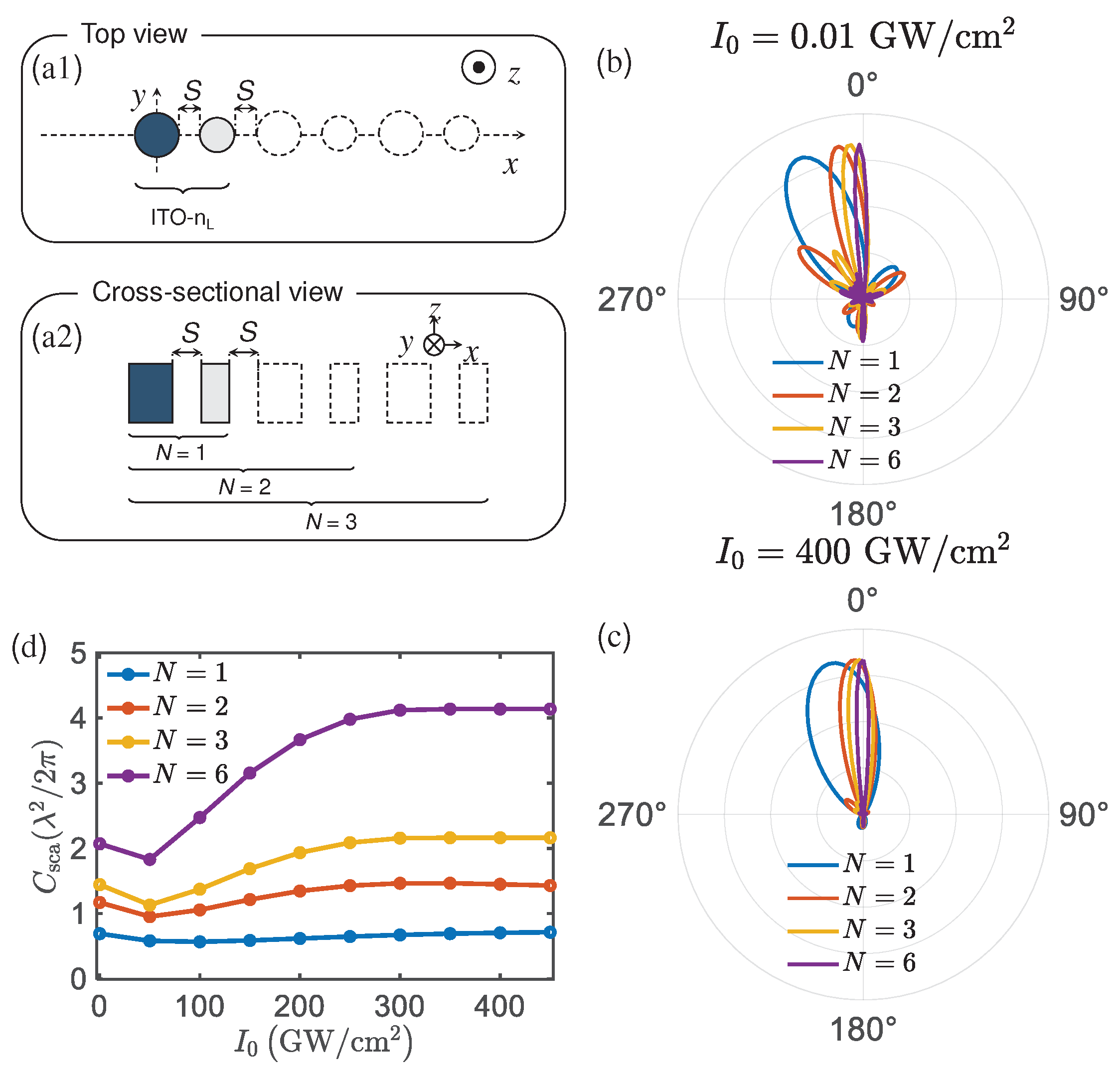
Finally, the influence of number of hybrid structure on radiation pattern is investigated, schematically illuminated in Figure 4(a1,a2). The radiation patterns are shown in Figure 4b,c at and in XZ plane, respectively. The deflection of 3D radiation patterns is prominent in XZ plane. A larger deflection is apparent for when compared to . The deflection starts lowering for intensities larger than . Here, we only pay attention to the variation in XZ plane. For and 6, the deflection angle in plane is , and from to , respectively. The main lobe angular beamwidth is significantly reduced as N increases. When , the influence on its deflection angle is reduced. To realize a practical application, at least 6 groups hybrids to be integrated into one design after simulation. Generally, the radiation pattern response, such as main lobe and deflection angle, of the finite structure will sustain in a comparable tunable response with that of ideal periodic structure. Therefore, it is possible to form micro-scale units with The proposed d design. Significantly, when added the hybrid group, the variation of the deflection angle gradually becomes smaller as the input intensity increases. The scattering cross section will increase as the the number of hybrid antenna increases as shown in Figure 4d. The 400 is very high and difficult to achieve practically. In fact, the refractive index does not change much after the intensity exceeds 100 .
3. Conclusions
In conclusion, we have presented a novel approach for achieving an active control over the deflection angle of radiation patter using ENZ material. Initially, we investigated the influence of incident light intensity on the radiation pattern of a single ITO structure, leveraging its strong Kerr effect. By comparing the results with the single ITO case, we then proposed a structured hybrid nano-antenna that exhibits distinct radiation patterns, accompanied by a dispersion angle of as the light intensity increases. Furthermore, as the number of ITO or hybrid antenna groups is increased, the width of the radiation main lobe decrease, offering potential application in light beam directivity control. Notably, the addition of hybrid antenna groups leads to a reduction in the deflection angle as the intensity increases. These actively tunable nanoantennas introduce a new degree of freedom for controlling the far-field radiation pattern based on the significant Kerr effect of ENZ materials.
Author Contributions
The following statements should be used “Conceptualization, Rasoul Alaee and L. C.; methodology,Lin Cheng; software, Y. W.; validation, L. C.; formal analysis, F. W.; investigation, L. C.; resources, Y. W.; data curation, F. W.; writing—original draft preparation, L. C.; writing—review and editing, X. L.; visualization, L. C.; supervision, L. C.; project administration, all; funding acquisition, L. C., F. W., X. L. All authors have read and agreed to the published version of the manuscript.
Funding
We would like to acknowledges the support of National Natural Science Foundation of China (98006511), Innovative Research Group Project of National Science Foundation of China (51821003), Natural Science Basic Research Program of Shaanxi, China (2022JQ-039), Science Foundation for Young Scholars (201901D211245, 202203021222021) and China Postdoctoral Science Foundation (2022M722923).
Data Availability Statement
Data underlying the results presented in this paper are not publicly available at this time but may be obtained from the authors upon reasonable request.
Conflicts of Interest
The authors declare no conflict of interest.
References
- Zhu, X.; Vannahme, C.; Hjlund-Nielsen, E.; Mortensen, N.A.; Kristensen, A. Plasmonic colour laser printing. Nature Publishing Group 2016. [Google Scholar] [CrossRef]
- Pogna, E.A.A.; Celebrano, M.; Mazzanti, A.; Ghirardini, L.; Carletti, L.; Marino, G.; Schirato, A.; Viola, D.; Laporta, P.; De Angelis, C.; Leo, G.; Cerullo, G.; Finazzi, M.; Della Valle, G. Ultrafast, All Optically Reconfigurable, Nonlinear Nanoantenna. ACS Nano 2021, 15, 11150–11157. [Google Scholar] [CrossRef]
- C..; Huang.; A..; Bouhelier.; J..; Berthelot.; G..; Colas.; des Francs.; E.. External control of the scattering properties of a single optical nanoantenna. Applied Physics Letters 2010, 96, 017402. [CrossRef]
- S., G.K.; S., R.; W., P.C.; Harry A. A. Zhu, X.; Vannahme, C.; Hjlund-Nielsen, E.; Mortensen, N.A.; Kristensen, A. Electro-optically tuanble multifunctional metasurfaces. ACS Nano 2020, 14, 6912–6920. [CrossRef]
- Li, J.; Chen, Y.; Yueqiang, H.; Duan, H.; Liu, N. Magnesium-Based Metasures for dual-function switching between dynamic holography and dynamic color display. ACS Nano 2020, 14, 7892–7898. [Google Scholar] [CrossRef] [PubMed]
- Yan, J.; Ma, C.; Huang, Y.; Yang, G. Dynamic radiative tailoring based on mid-refractive dielectric nanoantennas. Nanoscale Horizons 2019, 4. [Google Scholar] [CrossRef]
- Faniayeu, I.; Dmitriev, A. Dynamic Beam Steering by All-Dielectric Magneto-Optical Nanoantennas. CLEO QELS Fundamental Science, 2020.
- Ee, H.S.; Agarwal, R. Tunable Metasurface and Flat Optical Zoom Lens on a Stretchable Substrate. Nano Letters 2016, 16, 2818–2823. [Google Scholar] [CrossRef] [PubMed]
- Alaee, R.; Rockstuhl, C.; Fernandez-Corbaton, I. Exact Multipolar Decompositions with Applications in Nanophotonics. Advanced Optical Materials 2019, 7, 1800783–1. [Google Scholar] [CrossRef]
- Taminiau, T.H.; Stefani, F.; Segerink, F.B.; Hulst, N.V. Optical antennas direct single-molecule emission. Nature Photonics 2008, 2, 234. [Google Scholar] [CrossRef]
- Lin, C.; Alaee, R.; Safari, A.; Karimi, M.; Boyd, R.W. Superscattering, Superabsorption, and Nonreciprocity in Nonlinear Antennas. ACS Photonics 2021. [Google Scholar]
- Oulton, R.F.; Sorger, V.J.; Zentgraf, T.; Ma, R.M.; Gladden, C.; Dai, L.; Bartal, G.; Zhang, X. Birth of the nanolaser. Nature Photonics 2009, 3, 545–545. [Google Scholar]
- Sorger, V.J.; Zhang, X. Physics. Spotlight on plasmon lasers. Science 2011, 333, 709. [Google Scholar] [CrossRef]
- Russell, K.J.; Liu, T.L.; Cui, S.; Hu, E.L. Large spontaneous emission enhancement in plasmonic nanocavities. Nature Photonics 2012, 6, 459–462. [Google Scholar] [CrossRef]
- Lu, Y.J.; Kim, J.; Chen, H.Y.; Wu, C.; Gwo, S. Plasmonic Nanolaser Using Epitaxially Grown Silver Film. Science 2012, 337, 450–453. [Google Scholar] [CrossRef] [PubMed]
- Khajavikhan, M.; Simic, A.; Katz, M.; Lee, J.H.; Slutsky, B.; Mizrahi, A.; Lomakin, V.; Fainman, Y. Thresholdless nanoscale coaxial lasers. Nature 2012, 482, 204–7. [Google Scholar] [CrossRef] [PubMed]
- Alam, M.Z.; Leon, I.D.; Boyd, R.W. Large optical nonlinearity of indium tin oxide in its epsilon-near-zero region. Science 2016, 352, 795. [Google Scholar] [CrossRef] [PubMed]
- Boyd, R.W. Nonlinear optics; Academic press, 2019.
- Orad, R.; Enno, G.; Zahirul, A.M.; Israel, D.L.; Jeremy, U.; Boyd, R.W. Beyond the perturbative description of the nonlinear optical response of low-index materials. Optics Letters 2017, 42, 3225. [Google Scholar]
- Alaee, R.; Rockstuhl, C.; Fernandez-Corbaton, I. An electromagnetic multipole expansion beyond the long-wavelength approximation. Opt. Commun. 2018, 407, 17–21. [Google Scholar] [CrossRef]
- Alaee, R.; Filter, R.; Lehr, D.; Lederer, F.; Rockstuhl, C. A generalized Kerker condition for highly directive nanoantennas. Optics Letters 2015, 40, 2645. [Google Scholar] [CrossRef] [PubMed]
- Evlyukhin, A.B.; Novikov, S.M.; Zywietz, U.; Eriksen, R.L.; Reinhardt, C.; Bozhevolnyi, S.I.; Chichkov, B.N. Demonstration of Magnetic Dipole Resonances of Dielectric Nanospheres in the Visible Region. Nano Letters 2012, 12, 3749–3755. [Google Scholar] [CrossRef] [PubMed]
- Ming, Z.X.; Qiang, Z.; Jie, Z.S.; Zhen, L.Z.; Jun-Jun, X. Dual-band unidirectional forward scattering with all-dielectric hollow nanodisk in the visible. Optics Letters 2018, 43, 1275. [Google Scholar]
Figure 1.
Optical antenna based on ENZ material. (a) The real and imaginary parts of the intensity-dependent refractive index of ITO at the ENZ wavelength nm [19]. ITO disk with the diameter of of 600 nm and height of 400 nm in inset. (b) Two-dimensional (2D) in plane and (b1)(b2) three-dimensional (3D) radiation patterns at and , respectively. (c) Total scattering cross section (total) and different electric dipole (ED), magnetic dipole (MD), electric quadrupole (EQ), magnetic quadrupole (MQ) moments as a function of the input intensity. (d) Phase difference of multipoles of the single disk nanoantenna. (e) The real part of refractive index in -plane.
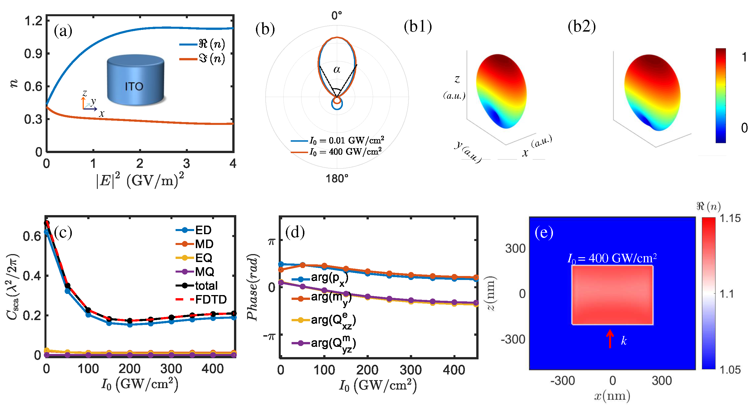
Figure 2.
Optical antenna based on the hybrid antenna. (a) Hybrid antenna formed by ITO ( nm, nm) and a lossless linear dielectric material with refractive index ( nm, nm) with x-polarized plane wave illuminated in the z direction. (b) 2D far-field radiation pattern of the hybrid antenna in plane at (blue line) and (red line), respectively. (b1)(b2) the corresponding 3D far-field radiation patterns. (c) Total scattering cross section and different electric and magnetic multipole moments as a function of the input intensity. (d) The real part of refractive index in -plane with .
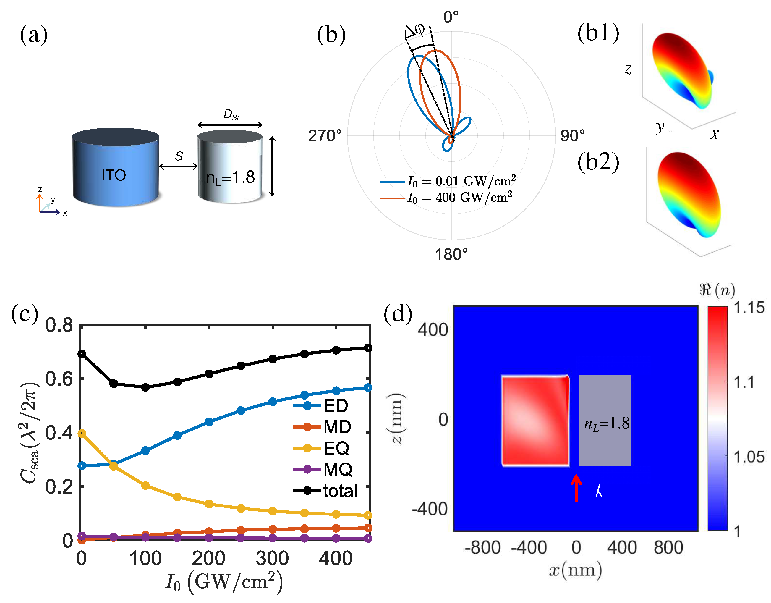
Figure 3.
Optical antenna of ITO material (a) Antenna model of ITO ( nm, nm). The space (S) between the ITO is 100 nm. (b) Radiation pattern under different amounts of ITO at . (c) Radiation pattern under different amounts of ITO at . (d) Total scattering cross section as a function of the input intensity under different amounts of ITO.
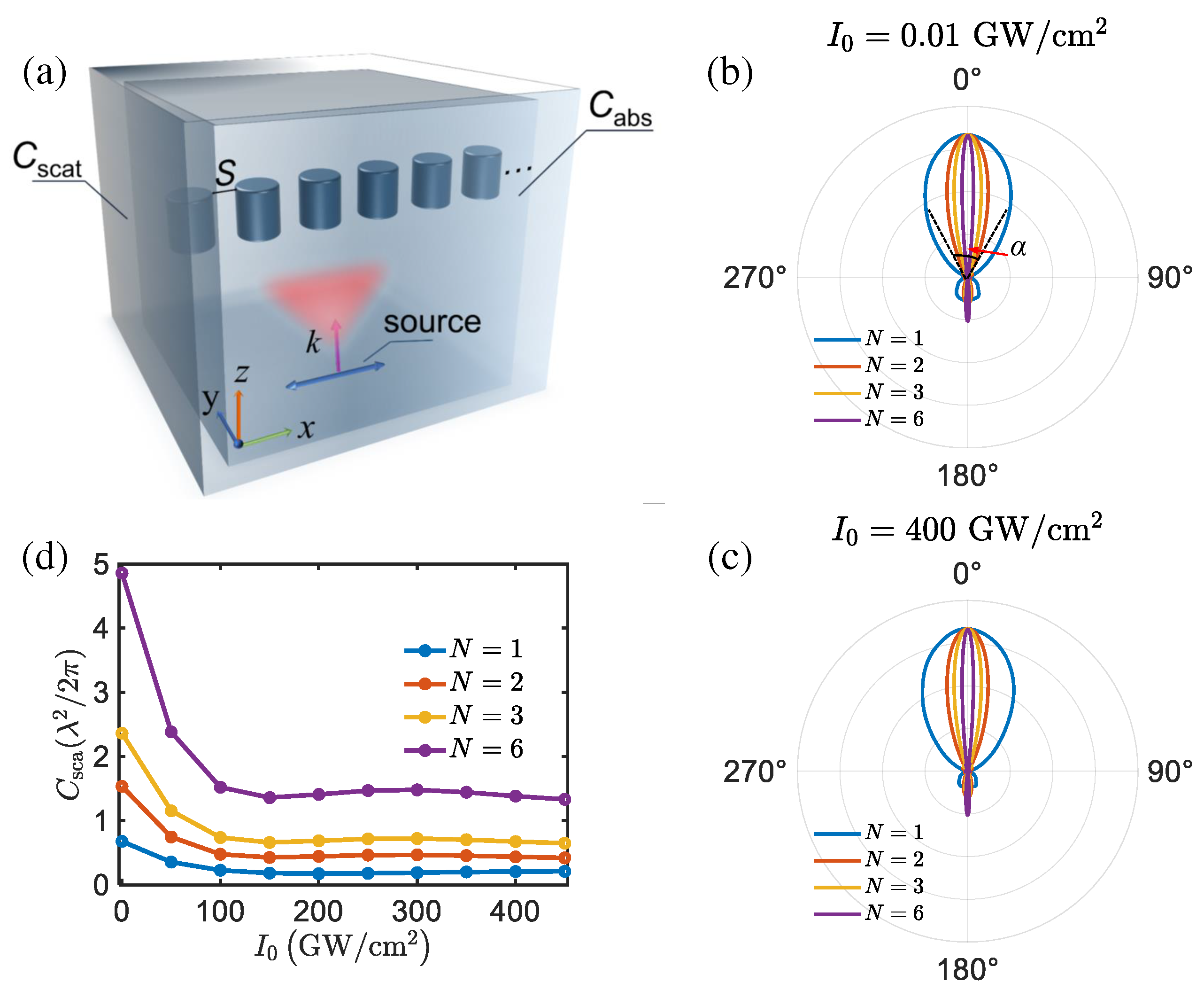
Figure 4.
Antenna of ITO-linear dielectric material(a1) Top and (a2) cross section view of the antenna groups ( nm, nm, nm, nm). (b) and (c) are the radiation patterns of the structure when the number of groups is and 6, respectively. The space between ITO and linear dielectric material is nm. (d) The scattering cross section as a function of input intensity under different number of groups.
Disclaimer/Publisher’s Note: The statements, opinions and data contained in all publications are solely those of the individual author(s) and contributor(s) and not of MDPI and/or the editor(s). MDPI and/or the editor(s) disclaim responsibility for any injury to people or property resulting from any ideas, methods, instructions or products referred to in the content. |
© 2023 by the authors. Licensee MDPI, Basel, Switzerland. This article is an open access article distributed under the terms and conditions of the Creative Commons Attribution (CC BY) license (http://creativecommons.org/licenses/by/4.0/).
Copyright: This open access article is published under a Creative Commons CC BY 4.0 license, which permit the free download, distribution, and reuse, provided that the author and preprint are cited in any reuse.


