Submitted:
24 May 2023
Posted:
26 May 2023
You are already at the latest version
Abstract
Product assembly is usually one of the last steps in the entire production process. This activity is typically entrusted to assembly workers because it is generally not possible to automate every type of product. For complex products, assembly can take a long time until the fitter learns the procedure and is able to assemble the product on his own. This contribution presents a cus-tom-developed system that enables controlled assembly of the extruder and can be used for complex and diverse products. The system serves to guide the fitter precisely and shows him which part to use at which time. The proposed system will show and describe on the display all necessary assembly steps and parts. Two-step verification is used to ensure that the correct part is picked from the stack. The contribution is supported by the implementation of a case study in a small company with a sample of 30 employees, which demonstrates that the proposed system shortens the extruder assembly time and significantly reduces the error rate. The presented solution is scalable and flexible, as it can be easily adapted to display the assembly steps of another product.
Keywords:
Poka Yoke
; Pick to Lights
; architecture
; effectiveness
; industrial engineering
1. Introduction
The term Poka Yoke, in English Mistake Proofing or Error Proofing, is composed of two Japanese words "Poka" - Unintentional mistake and "Yokeru" - Prevent. The Poka Yoke concept has been used in various forms since the beginning of mass production. Its author was the Japanese innovator Shigeo Shingo, who was the first to present this method at Yamada Electronic company in 1961. However, like most Japanese methods, this one became better known around the world only after its use in the United States of America in the 80s and 90s of the last century. The initiator for the Poka Yoke implementation in the American automobile industry was the expert Hiroyuki Hirano, who successfully adapted it to the requirements of the American industry [1].
The design of an "error prevention tool" is a procedure in which mechanisms are introduced into the process environment or the process itself to prevent a given erroneous operation from occurring at all. This method has a preventive nature and is based on the principle of zero error occurrence in the process. Control elements focus on the initial stage of the process and the inputs themselves before the active activities that add additional value to the inputs occur [2].
An error in the production process is defined as any deviation from the predetermined technological, possibly working, drawing requirements, or even the smallest deviation from the correct product functioning. Almost most mistakes can be prevented in some way. The cause of errors in the process is, in most cases, the employee himself [3].
Errors can generally be divided into two categories:
1. Process errors - arise as a result of incorrect production environment design, workplace, procedures, etc.
2. Errors caused by employees - the human factor is at work here
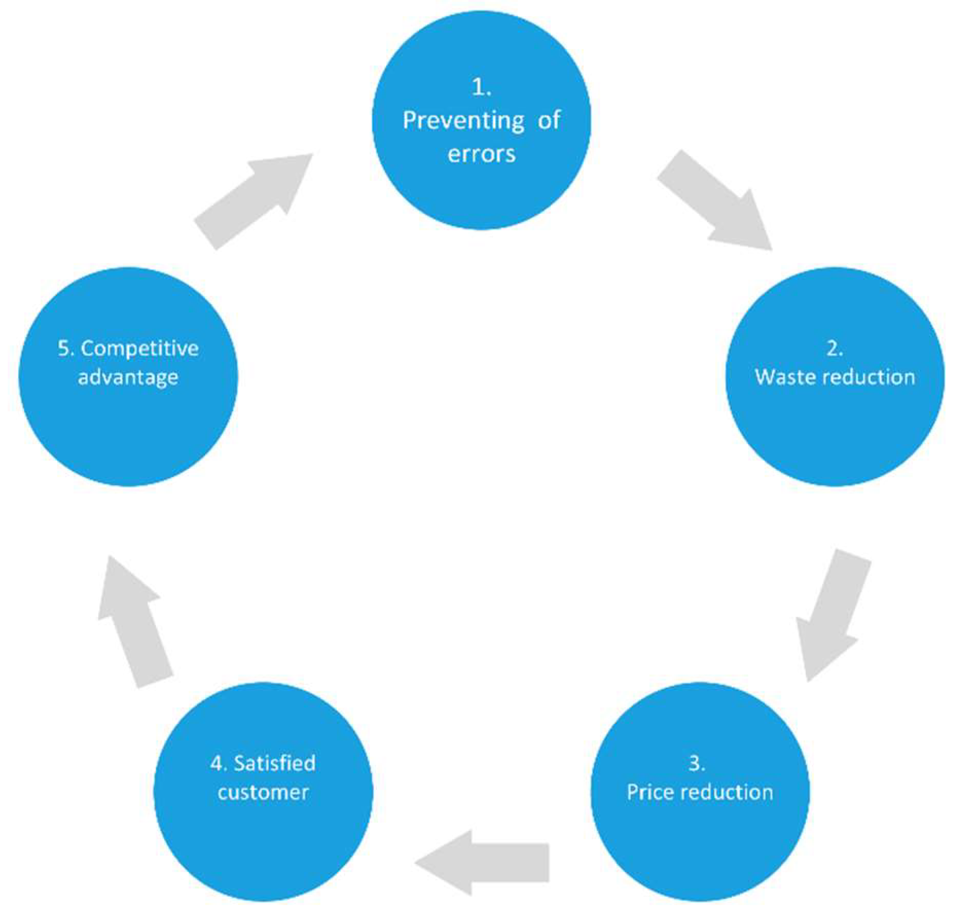
The main mission of the Poka Yoke method is to identify and prevent errors. If they do occur, it is important that the defective product does not reach the customer [4].
Figure 1.
The Poka Yoke principle.
1.1. Literature Review
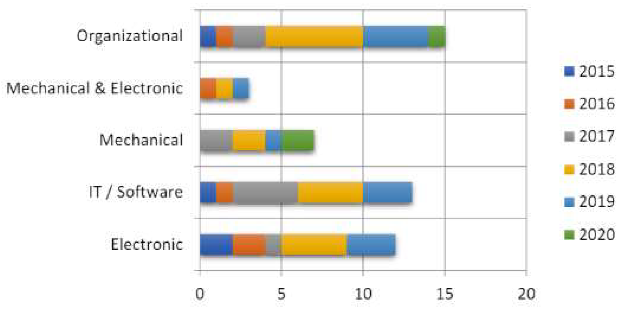
Poka-Yoke is an approach that enables an effective way to improve process quality. Its basic principle is the identification of errors already at their source and the prevention of subsequent errors. The use of the Poka Yoke approach has been applied for several years in various areas, e.g. the authors in [5] described the application in the automotive industry in the production of engines and assembly of gearboxes, in [6] they used Poka Yoke in image analysis and fault identification. The image was captured by a regular video camera and then converted into a monochrome matrix, which is capable of identifying and classifying the type of failure. Another application of Poka Yoke is shown in the production of air pipes [7], in the production and assembly of compressors [8]. A more comprehensive overview of the application of this approach is given by the authors in [9]. Based on their analysis and evaluation of 50 literary sources, that discussed the possibilities of applying Poka Yoke in the elimination of errors, they presented the following division of individual areas (Fig. 2).
Figure 2.
Literature review of Poka Yoke.
These were mostly solutions in production areas. The application of Poka Yoke is also possible in the field of business operations. The proposal for such an application is presented in the paper [10]. However, the present brings new elements and connections to this approach as well. We can see this in the contribution of the authors [11], who propose an effective Poka Yoke solution by combining convolutional neural networks and lean manufacturing tools in the development of intelligent production lines. In automated production lines, human error is the most common cause of failures. The elimination of this factor is described by the authors in the paper [12].
In the presented article, we are focusing on the possibility of using Pick to Light to eliminate errors caused by operators.
1.2. Basic functions of Poka Yoke
Every error occurring in the process has two stages of its development: either it is soon to appear or it has already fully manifested itself. The knowledge that the error could appear soon is called prevention, or a preventive measure. Notice of an error that has already manifested itself is called detection. The Poka Yoke method has three basic functions with respect to its interventions to an already existing error [13]:
1) Shutdown function;
2) Control function;
3) Warning function
The control and shutdown function – is used to identify errors and to possibly interrupt production if a given error occurs. By combining the two functions of the Poka Yoke method, it is possible to achieve the maximum protective effect in the discovery and termination of serial errors arising during serial production in large batches. When detecting the presence of an error in the process, the production flow is stopped, which prevents defects and makes production more efficient. On the other hand, the elimination of random recoverable errors is very costly [14].
Warning function - has the obligation to notify the employee of the error occurrence on the production line, equipment or machine. As a typical example, a warning with light signalling when an error is found can be mentioned. Alerted by a light signal, the employee finds the given problem, evaluates it and then decides on appropriate measures to eliminate it. This is a relatively cheaper solution than, for example, the control function. The disadvantage is the fact that the employee is responsible for interrupting the process. This means that in the event of his inattention, failures may occur [14].
After all, the fact remains that man is forgetful and has a tendency to make various oversights. Therefore, employees are very often warned that they are making mistakes. This approach subsequently intimidates, disgusts employees, lowers work morale and, most importantly, does not solve the problem. Poka Yoke is a technique that deals with solving any problem. We divide individual types of means of this method based on their functions and settings into [13], [15]:
- Control device located directly at the source of the error - before the failure occurs. A typical example is a pin that prevents incorrect orientation of the workpiece from being processed. These means are often the most effective solution.
- 100% control for detection - using a low-cost sensing device such as a limit switch. In case of the presence of any abnormality, light or sound signaling is activated.
- Immediate measures to stop the operation in the event of an error - An example is a blocking circuit that automatically shuts down the machine from operation.
2. Materials and Methods
Means used to detect errors in the process may not immediately represent an increase in costs. Examples include a locking pin located in a jig or a limit switch that responds to the location of a part. However, the very application of these means should not be an attempt to eliminate the need for specific work skills [16].
Another example can be a counter or an alarm that prompts the worker to perform a certain work task. That action can be moving the defective piece to the space for failures. With the help of a sensor located in the storage space, the presence of a defect will be recorded, and only then can the given process continue. The above-mentioned examples do not only represent error prevention, they depend on the employee, who must react accordingly. Properly motivating and involving employees in the product improvement or the process itself, these means can significantly reduce the number of errors [17].
Company managers must themselves have an idea in the field of quality management and this idea must be fully supported by the creation of a corporate culture through which employees would be motivated and this vision would be accepted. Either by providing time and support resources to work teams when analyzing a problem or by introducing a reward system aimed at motivating employees [18].
We can use a wide variety of means to detect errors and malfunctions. Sensors used in the Poka Yoke method are divided into two groups [19]:
- a)
- Contact means - are those that touch the tested part. The most frequently used tools are limit switches and micro switches. These can track the presence of a piece, cutting tool or mold and they are special in their flexibility. They are used to ensure the interruption of the process until the given piece takes the correct position or if it has the wrong shape. The mentioned method also uses other means based on contact, such as: distance switches, displacement, position, metal passage sensors, and a number of other mechanical solutions
- b)
- Non-contact means - do not require direct contact. They find their application when working with translucent, opaque and transparent pieces. Photoelectric switches can be mentioned as a type of non-contact means. These work in two ways. The first way is to work with transparent objects. In that case, two units are used, one of which sends a light beam to the other, which is its recipient. This type is either in the on state, that is, if the light passes through the object, or in the off state, if there is an obstacle in the path of the beam. The second way is the reflex type of photoelectric switch. It reacts to the presence of an object only after the reflection of a light beam from its surface.
2.1. Pick to Light system
Poka Yoke minimizes the possibility of unintentional errors or errors due to inattention to almost 100%. This group of solution systems also includes other methods, such as Pick by Voice, Pick and Work, Pick by Vision and so on. Even though these systems are mostly implemented in the field of logistics, they are increasingly finding their place in the field of assembly as well [20].
Devices using the principles of the Pick to Light (PTL) system are adapted so that a given assembly or storage cannot be carried out in more than one way. The main means of these devices are optical signalling elements that gradually light up, which are placed above each warehouse position, respectively cell. When a component is removed from any position, the light beam will be interrupted by the worker's hand, causing the corresponding signalling to go out and another signalling to be lit in another position. The system is capable of notifying the worker of a possible error with a light or sound warning [21].
In this way, the presence of paper expenses, assembly sheets, etc. is not necessary. The flawless worker workflow is monitored by a sophisticated system that not only navigates him during assembly but also warns him if he has made a mistake
From the point of view of increasing the production process quality, the Pick to Light systems represent the philosophy of "zero error rate". Visual control of the production process is used in several industrial areas (electrical and automotive industry, logistics, storage, etc.) [22].
The main benefits of Pick to Light systems are:
- Increasing work productivity;
- Improving quality;
- Reducing the occurrence of errors to zero;
- Continuous inventory;
- Connection to ERP and warehouse systems;
- Increasing flexibility;
- Speed of new personnel training.
The Pick to Light system is used in the order picking environment. It allows the employee (male or female) to quickly and easily find the right position using lights or LED displays. Each tag represents an item in the storage location. In addition to guiding the employee to the exact location, the light shows the exact amount of items in the rack's bins. The system requires confirmation before the item is selected.
As Fig. 3 shows, the architecture of the PTL system consists of the following components.
- Rack consisting of multiple pick to light units.
- Bar code reader for scanning items inserted and removed from the rack.
- Control unit/ controller (network or wireless) connected to the pick to light system.
- Router or network hub.
- Remote PC installed with real-time material inventory management software.
Figure 3.
Pick to Light system architecture.
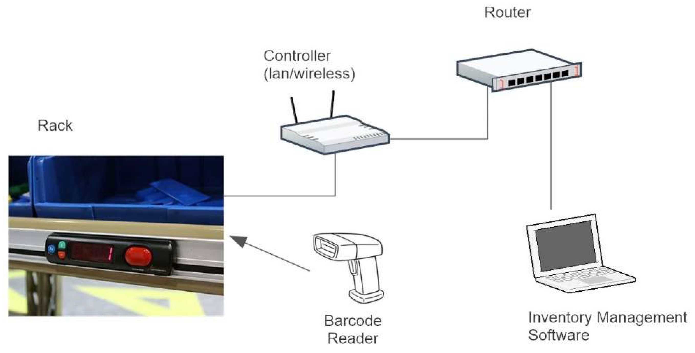
The PTL system works as follows. In the rack consisting of several rows, an optical sensor and a control unit are mounted on each controlled cell. Each row has several cells connected to a control unit that ensures sensing and informing the employee. Subsequently, several units are connected to a central router, which sends all information to the inventory management software (IMS). The unloading and storage of individual components in the cell is recorded using a barcode reader [23].
This information is sent to IMS, which informs the operators in the warehouse about the box preparation with the exact number of parts. After it is inserted into the IMS cell, it keeps inventory records and loads the program for the specified assembly. According to the requirements, the individual cells are explained in the exact order and the number of pieces is displayed on the Led display. When selecting a component, the employee's hand is read using an optical sensor and the operation is considered completed. Subsequently, another cell is illuminated and the employee repeats the operation. The individual steps are entered into the control units connected to the router.
2.2. Procedure for implementing the Poka Yoke method using Pick to Light
Part of the presented implementation is the creation of the Pick to Light device, labelled Spider 1, and the assembly model procedure part of the extruder with a motor. The goal is to create a training workplace for employees with a focus on increasing production efficiency. Subsequently, we designed the assembly procedure of the sample component, which allows the simulation of the Poka Yoke method. An important prerequisite for the model workplace creation was the acquisition of the necessary knowledge in the field of Pick to systems, or Pick by and Poka Yoke methodology. With the proposed simulation workplace, it is possible to create assignments, prepared by employees for the creation of assembly procedures [24]. As mentioned in the previous text, the term Pick to Light belongs to the group of solution systems using the principles of the Poka Yoke method. This means that it minimizes the possibility of unintentional errors, or errors due to inattention to almost 100%. The given device ensures that the given assembly or storage cannot be carried out in more than one way. The presence of paper expenses, assembly sheets, etc. is not necessary. A sophisticated system monitors the worker's flawless workflow, which not only navigates him during assembly but also warns him if he has made a mistake [25]. The procedure for programming the given device, as well as its functioning, is described in the next part of the paper.
The basic elements of the Pick to Light device are the following components:
- Optical-reflective sensors with LED indicators – The sensors have a simple construction that consists of 2 LEDs and a comparator. The principle of operation is as follows: one of the LEDs emits infrared light, which, after bouncing off an obstacle, returns to the photodiode. The task of the optical-reflective sensor is to detect the interruption of the continuously transmitted infrared beam due to someone else's fault (operator's hand, plastic rod, etc.). The indicator colors are red and green. The green color represents the possibility of using a specific container. The red color has a double meaning: firstly, it represents a sign of programming the device, and secondly, it indicates, together with an audio signal, a warning about an incorrectly used container. The PTL device contains eight such sensors stored in the upper bars of the device. The sensor's sensitivity was adjusted by a trimmer built into the printed circuit board [26].
- Control unit with display and power supply – The heart of the control unit is a processor labelled ATmega 128-8 bit AVR, which ensures sufficient performance for the operation of the system and its control. The control unit is controlled by a program called SPIDER1FINAL, which was created in Bascom-AVR IDE (2.0.8.1).
- The control unit includes an integrated display unit marked BOLYMIN BC1602A. BC1602A is an LCM character, 2x16 STN yellow-green display with LED backlight.
- The control unit, represented by an instrument aluminium box with an inclined display, is powered by a 5V/DC power adapter. The ports labelled "Drawer 1-4" and "Drawer 5-8" connecting the control unit to the PTL device are located on the back of the control unit together with the connector for connecting the AC/DC adapter.
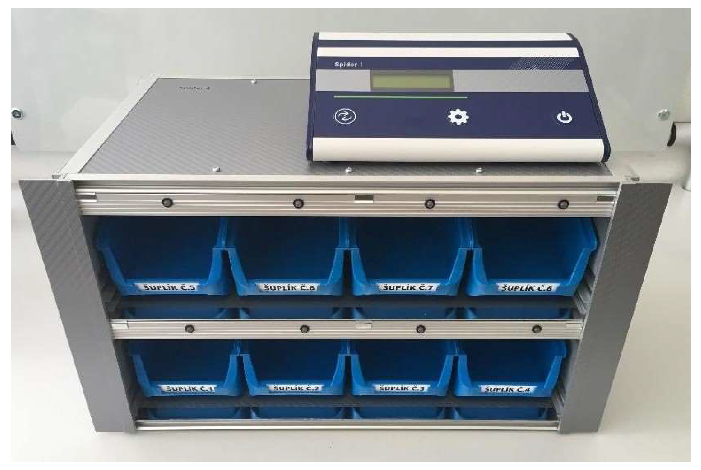
- Functional unit of the PTL device – The body of the Spider 1 device consists of a rectangular aluminium structure, divided by a 2 mm thick aluminium plate into two parts. Spider 1 is protected from the side by aluminium sheets, the surface of which is covered with a self-adhesive carbon 3D film. This increases the device's resistance to scratches, abrasions, or minor damage caused when it is transported. The interior is filled with plastic containers with dimensions of 75x102x160 mm. Since these are smaller types of containers, their rear parts are raised at a 45° angle for better insertion and removal of the necessary components. The magazines can also be removed from the device and inserted according to the needs of the person handling the Spider 1. Above the container, there are sensors and LEDs, which are placed in aluminium rails.
- Spider 1 is a light, compact and portable device that can be carried according to the customer needs.
- Other components of the PTL device are:
- 2 pieces of connecting cables – The cables were made by modifying the connecting cable type SCART-SCART. It is two-way, 15 pin cables with connectors D-SUB MALE. Due to their correct connection, the cables are distinguished from each other by the color of the cover on the grey and black cable connector.
- Power supply for the device PTL– Specifications: AC/DC. Model 10 W. Input: 100 – 240 V 50-60 Hz. Output 5V/ 2A. Output connector 5,5/2,1 mm.
Figure 4.
Constructed Pick to Light device labelled Spider 1.
2.3. Model component
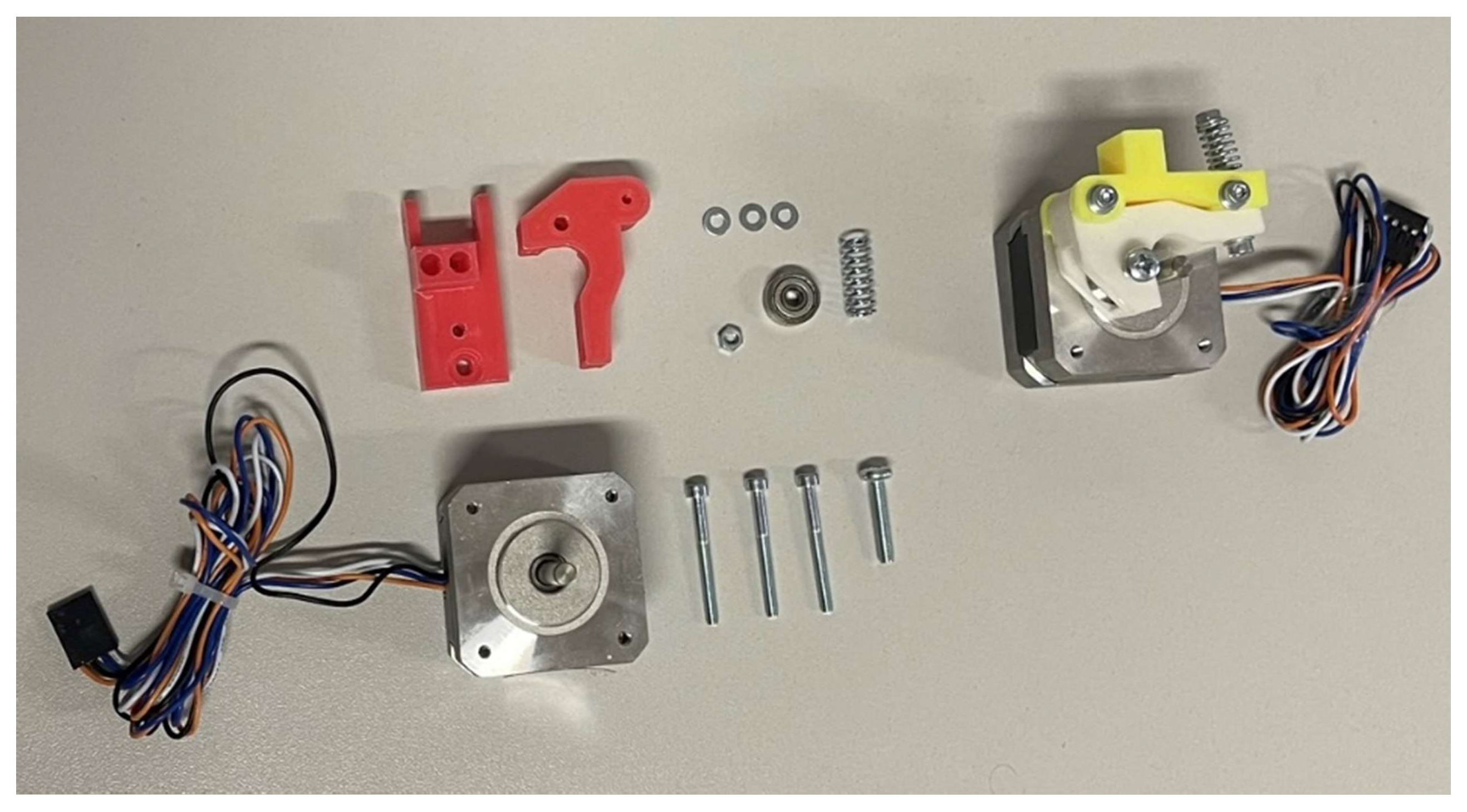
In the article, we focused on the assembly of small material components. The model part is an extruder with a motor serving as a filling feeder in 3D printers, see Fig. 5. [27] It is a modular part composed of several smaller components. For testing purposes, its 8 basic parts described in the assembly procedure will be sufficient. [28]
Figure 5.
Extruder with motor in unfolded and folded state.
Workplace - it consists of a work table used to place the created PTL device. This is a modular table, manufactured by Bewatech.
Assembly procedure of the model part - This consists of a graphic and verbal assembly procedure of the extruder with a motor.
1 step – Insertion of bearing 624 into plastic part A.
2 step – Fixing the bearing with a screw M5 x 20.
3 step – Connection of plastic parts A and B.
4 step – Attaching parts A and B to the motor with M5 x 25 screws with a washer.
5 step – Transverse connection of parts A and B with M5 x 30 screw with washer.
6 step – Securing the M5 screw with a washer, a spring washer and a nut.
Components for assembly:
- Single row ball bearing type 62 with diameter 5mm: Bearing 6208 STN 02 4630.
- M5 hemispherical head screw with shank length l= 20 mm, with the mechanical properties of the material 5S, without surface treatment STN 02 1146.
- M5 socket head cap screw with shank length l= 25 mm, with the mechanical properties 8G STN 02 1143.
- Washer for screws with a hexagonal head with a diameter 5,3 mm from steel 11 423, without surface treatment STN 02 1720.
- Screw with cylindrical head and internal hexagon M5 with the length shaft l= 30 mm, with the mechanical properties 8G STN 02 1143.
- Washer for screws with a hexagonal head with a diameter 6,4 mm from steel 11 423, without surface treatment STN 02 1720.
- Helical cylindrical compression spring with diameter D1= 7,2 mm and length l0= 18 mm STN 02 6001.
- Precision hexagonal low nuts M5 from precision class material 8, without surface treatment STN 02 1401.
Working tools:
- L hexagonal allen key 2,5 CRV 18x56 mm;
- Phillips screwdriver PH 0x75
3. Results
The complex methodology of the test consists of two parts. The first part simulates the production process of the model part construction without introducing the PTL device. In the second part, the PTL device is already implemented in the investigated process. The main monitored and compared parameters are mainly the length of one production cycle, one production batch, the total error rate of the process, etc. Basic tendencies of carrying out training in a simulated environment. Both tests were performed on a selected sample of 30 participants. Basic socio-demographic data are presented in the table 1.

Table 1.
Participants’ socio-demographic characteristics.
| Sex | % | Year | % | Education | % | Work assignment | % |
|---|---|---|---|---|---|---|---|
| Male | 14 | 21-30 years | 14 | Basic | 2 | Assembly worker | 13 |
| Female | 16 | 31-40 years | 11 | Secondary vocational | 17 | Production worker | 12 |
| 41-50 years | 3 | High school diploma | 4 | Service personnel | 3 | ||
| 51-60 years | 2 | University education | 8 | An engineer | 5 |
3.1. Test before application of PTL
With the constant produced parts improvement, components or sometimes entire objects, the number of different variants of their construction also increases. This puts more emphasis on the number of components that need to be in the workplace in a given situation. Individual components are usually prepared either in containers or in complete sets, and the worker chooses the ones he needs based on the printed specification or assembly procedure. The employee entrusted with the assembly of the model part has trays with various components placed on the work table, which represents the workplace. Based on the prepared assembly procedure, he prepares the individual containers and starts assembling the model part.
This classic approach to assembly activities carries several negatives. The most important one can be ranked:
- -
- The length of the assembly procedure training unnecessarily extends the start of the assembly process;
- -
- Frequent viewing of the assembly procedure - another unnecessary waste of time;
- -
- The constant pressure exerted by the moderator causes inattention and tension, resulting in errors and inappropriate pieces;
- -
- The simulation of such a situation arouses unnecessary nervousness and uncertainty in the student;
- -
- The workplace becomes uncomfortable and less and less psychologically bearable.
Table 2.
Time measurement before the PTL introduction.
| Operation/worker (s) | 1 | 2 | 3 | 4 | 5 | 6 | 7 | 8 | … | 30 | Average time (s) |
|---|---|---|---|---|---|---|---|---|---|---|---|
| Components and tools preparation | 20 | 22 | 21 | 30 | 22 | 25 | 24 | 26 | … | 26 | 24.7 |
| Training | 5 | 10 | 12 | 10 | 13 | 11 | 5 | 6 | … | 7 | 11.16667 |
| Studying the procedure | 30 | 27 | 29 | 25 | 35 | 32 | 26 | 24 | … | 26 | 29.66667 |
| Assembly of one part | 65 | 65 | 69 | 62 | 63 | 65 | 68 | 70 | … | 61 | 63.83333 |
| Assembly of the production batch (10 pcs.) | 726 | 736 | 820 | 862 | 763 | 734 | 792 | 812 | … | 826 | 789.7667 |
| Connection check | 5 | 4 | 6 | 3 | 5 | 6 | 4 | 6 | … | 5 | 4.433333 |
| Storage in a box | 4 | 4 | 6 | 4 | 6 | 8 | 4 | 9 | … | 5 | 6.433333 |
| Total assembly time 1pc. | 129 | 132 | 143 | 134 | 144 | 147 | 131 | 141 | … | 130 | 140.2333 |
| Total assembly time 10 pcs. | 871 | 875 | 1002 | 997 | 943 | 942 | 927 | 1018 | … | 985 | 963.9667 |
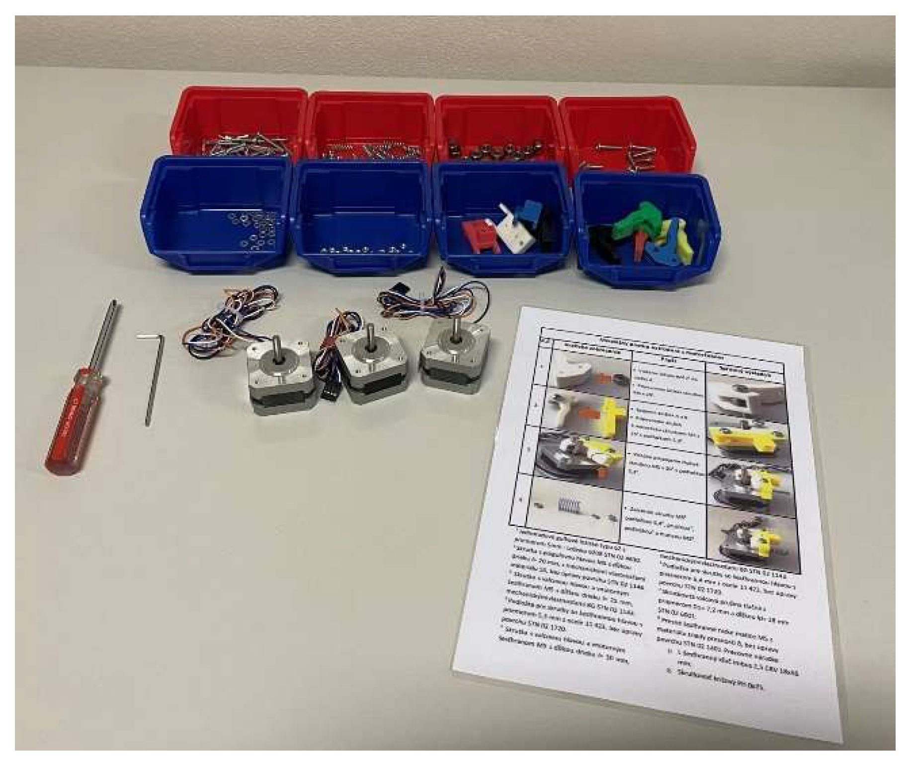
As already mentioned, the test was carried out on a selected sample of 30 employees of an SME company. We gradually measured individual preparatory times and assembly operations, which we recorded in a table. The first step was the components and individual tools needed for assembly. This operation ranged from 20-30 seconds, with an average workplace preparation time of 24.7 seconds per production batch of 10 pieces. The second operation was the initial employee training on safety and health protection. These operations lasted 5-20 seconds, with an average training time of 11.2 seconds. The third operation is studying the technological procedure printed in A4 format (see figure 6). The initial study took place in the range of 24-37 seconds with an average time of 30 seconds. Subsequently, the component was assembled according to the manual described in subsection 2.3. Assembly consisting of 6 steps was in the range of 56-70 seconds, while the average assembly time of one component was 63.83 seconds. Each employee subsequently repeated the individual assembly 10 times and the times were recorded in a table. Subsequently, an optical check of connection and functionality took place. It is a non-time-consuming test that lasted 4.5 seconds on average. The last operation was the final storage of the assembled extruders in the transport box. This operation lasted from 4 to 9 seconds with an average time of 6.43 seconds.
Figure 6.
Assembly workplace without PTL.
3.2. Test with PTL application
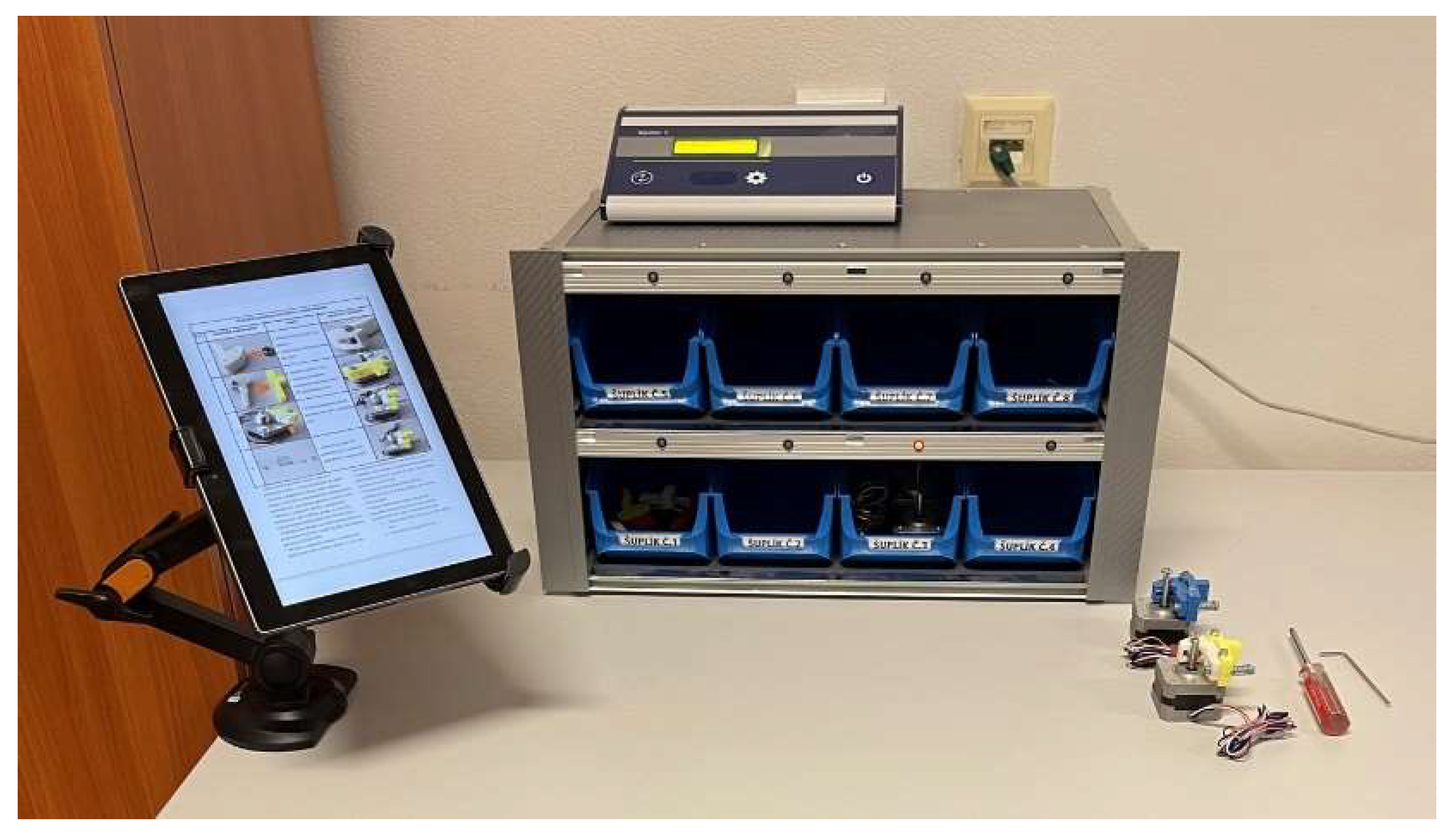
The manufacturing process of assembling the model part begins with placing the PTL device at the workplace and describing its basic functions. An employee posing as a (manager) of the dummy process places the stacks in the device and runs diagnostics on its hardware. It will then program the individual steps and thus enable the assembly process to start. Then the testing of a selected sample of employees who use the PTL system will take place.
Figure 7.
Assembly workplace with PTL.
Important parameters that were analyzed after applying the principles of the Poka Yoke method are mainly the length of production of one piece, the entire production batch and the presence of incorrectly made parts. An important parameter is also the employee feeling comparing both types of simulated situations.
Table 3.
Time measurement after introduction of PTL.
| Operation/worker (s) | 1 | 2 | 3 | 4 | 5 | 6 | 7 | 8 | … | 30 | Average time (s) |
|---|---|---|---|---|---|---|---|---|---|---|---|
| Components and tools preparation | 18 | 20 | 17 | 23 | 22 | 25 | 23 | 17 | … | 22 | 22.633 |
| Training | 5 | 7 | 9 | 5 | 12 | 8 | 6 | 9 | … | 5 | 8.8 |
| Studying the procedure | 9 | 12 | 15 | 15 | 16 | 20 | 18 | 17 | … | 12 | 14.433 |
| Assembly of one part | 58 | 56 | 57 | 56 | 61 | 60 | 61 | 67 | … | 53 | 57.4 |
| Assembly of the production batch (10 pcs.) | 621 | 632 | 712 | 642 | 684 | 657 | 544 | 702 | … | 573 | 639.6 |
| Connection check | 4 | 6 | 5 | 3 | 6 | 5 | 2 | 3 | … | 3 | 3.966 |
| Storage in a box | 3 | 4 | 2 | 3 | 4 | 6 | 2 | 7 | … | 4 | 4.333 |
| Total assembly time 1pc. | 97 | 105 | 105 | 105 | 121 | 124 | 112 | 120 | … | 99 | 111.566 |
| Total assembly time 10 pcs. | 723 | 771 | 823 | 745 | 834 | 820 | 631 | 845 | … | 682 | 768.466 |
After the set limit in the form of the number of pieces or the elapsed time is over, the recorded information is compared and analyzed. The first was the components and tools preparation. A reduction in time will be noted during this operation. We achieved this by inserting ready-made assembly boxes with components into the body of the Spider 1 device. During this operation, the running time was reduced from 24.7 to 22.63 seconds. During the second training operation, our running time was reduced from 11.16 to 8.8 seconds. We achieved this mainly because the employee was familiar with the use of the PTL Spider 1 system. The biggest time saving of more than 50% of the time, was achieved when studying the procedure, as the PTL system illuminates the order in which the individual components of the extruder are to be assembled. The total assembly time of 1 component was reduced from 63.8 to 57.4 seconds, which represents a saving of around 11%. A more significant reduction in the average extruder assembly times occurred when assembling a production batch of 10 pieces when after studying and testing, the time was reduced from 789.76 seconds to 639.6 seconds, which represents a saving of almost 20% for 10 pieces. When checking the connection, there was only a slight reduction in the average time. A more significant reduction in time occurred after the PTL application when storing in the handling box, which we attribute to the fact that the employees were already familiar with where and how to store the extruder from previous testing.
3.3. Evaluation of the Pick to Light system introduction
When evaluating the process's efficiency, we focused on several factors. The introduction of the PTL system can bring many advantages for operations that ensure the picking of goods. Figure 8 and Figure 9 show the assembly times of individual workers for 1 piece and a production batch.
Figure 7.
Comparison of assembly times before and after the PTL introduction for the 1 piece.
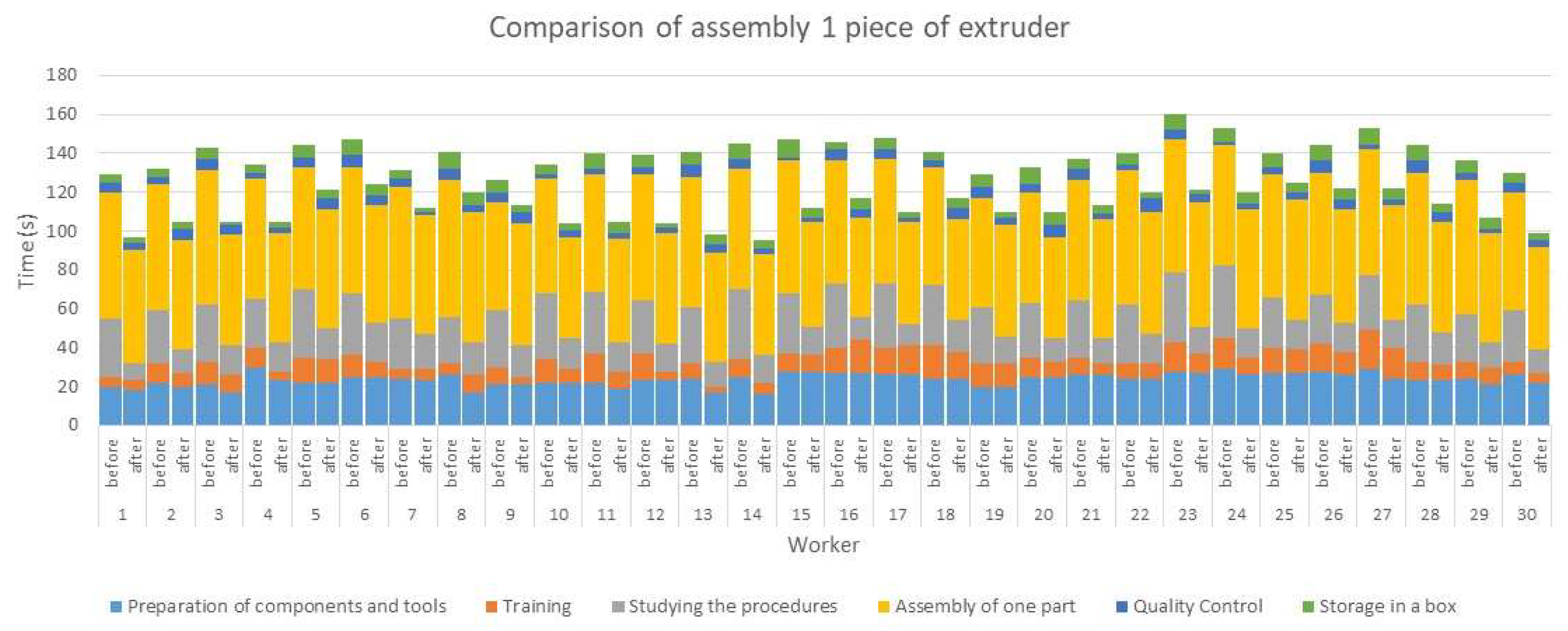
When assembling 1 piece of the extruder, we observe the greatest reduction in time for worker number 14, where the total time was reduced from 145 seconds to 95 seconds, which represents a reduction of time by 35%. It was a 25-year-old man with a high school education who worked as an assembly worker. His assembly experience contributed to a significant reduction in time. In general, he praised the system tested by us. The smallest time saving was achieved by worker number 9, from the time of 126 seconds of classic extruder assembly, his time was reduced to 113 seconds, which represents a shortening of the operation by 11%. Worker 25 also achieved the same result of shortening by 11% from 140 seconds to 125 seconds. In the first case, it was a 43-year-old woman and a service worker, in the second case, a 54-year-old man and a production worker. Both of them answered after 1 test that the designed device seemed small and difficult to operate.
Figure 8.
Comparison of assembly times before and after the PTL introduction for the production batch.
Figure 8.
Comparison of assembly times before and after the PTL introduction for the production batch.
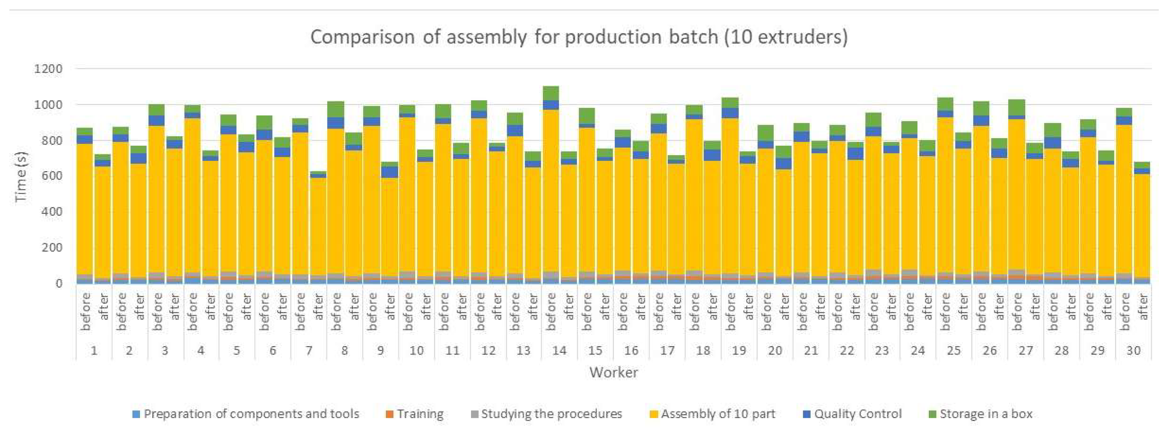
During the production batch assembly, we can state that the preparatory operations have not changed with respect to the production batch, but we have recorded a time saving during the production batch assembly. The greatest time savings of up to 33% was achieved by worker number 14. The smallest saving of only 7% was achieved by worker number 16, and his total time was reduced from 859 seconds to 798 seconds. All tested workers said that they like the introduction of PTL system and can imagine its deployment in the company in the future.
Another evaluated factor that we focused on was the error occurrence before and after the PTL introduction shown in tables 4 and 5.
Table 4.
Errors occurrence before the PTL introduction.
| Assembly/ Worker | 1 | 2 | 3 | 4 | 5 | 6 | 7 | 8 | 9 | 10 | 11 | 12 | 13 | 14 | 15 | 16 | 17 | 18 | 19 | 20 | 21 | 22 | 23 | 24 | 25 | 26 | 27 | 28 | 29 | 30 |
|---|---|---|---|---|---|---|---|---|---|---|---|---|---|---|---|---|---|---|---|---|---|---|---|---|---|---|---|---|---|---|
| 1 | x | x | x | |||||||||||||||||||||||||||
| 2 | x | x | x | x | x | x | x | x | ||||||||||||||||||||||
| 3 | x | x | ||||||||||||||||||||||||||||
| 4 | x | x | x | x | x | |||||||||||||||||||||||||
| 5 | x | |||||||||||||||||||||||||||||
| 6 | x | x | x | x | x | |||||||||||||||||||||||||
| 7 | x | x | x | x | ||||||||||||||||||||||||||
| 8 | x | x | x | |||||||||||||||||||||||||||
| 9 | x | x | x | |||||||||||||||||||||||||||
| 10 |
Table 5.
Error occurrence after the PTL introduction.
| Assembly/ Worker | 1 | 2 | 3 | 4 | 5 | 6 | 7 | 8 | 9 | 10 | 11 | 12 | 13 | 14 | 15 | 16 | 17 | 18 | 19 | 20 | 21 | 22 | 23 | 24 | 25 | 26 | 27 | 28 | 29 | 30 |
|---|---|---|---|---|---|---|---|---|---|---|---|---|---|---|---|---|---|---|---|---|---|---|---|---|---|---|---|---|---|---|
| 1 | x | x | x | |||||||||||||||||||||||||||
| 2 | x | x | x | x | x | x | x | |||||||||||||||||||||||
| 3 | x | |||||||||||||||||||||||||||||
| 4 | x | x | x | x | x | x | ||||||||||||||||||||||||
| 5 | ||||||||||||||||||||||||||||||
| 6 | x | x | ||||||||||||||||||||||||||||
| 7 | x | |||||||||||||||||||||||||||||
| 8 | x | x | ||||||||||||||||||||||||||||
| 9 | ||||||||||||||||||||||||||||||
| 10 |
From the mentioned measurement of errors, we can conclude that 30 workers made 34 errors during the assembly of 10 extruders before the introduction of the PTL system. After the introduction of our PTL system, only 22 errors occurred, which represents a decrease in the error rate by 35%. As can be seen in Table 5, the errors significantly decreased at 7, 8 and 9 repetitions. Our assumption is that by implementing several repetitions and getting used to the PTL system, we can significantly reduce the error rate.
5. Conclusions
In general, Poka Yoke is a system aimed at preventing production errors and minimizing costs associated with error corrections. The implementation of Poka Yoke rests in the identification of potential errors in production processes and the subsequent implementation of measures to prevent these errors. The PTL system can be an effective tool for implementing Poka Yoke in production engineering. First of all, the PTL system allows the process of dispatching goods to be simplified by using light indicators that direct employees to retrieve the correct goods from specific positions. This reduces the risk of making a mistake by choosing the wrong product. Therefore, implementing a PTL system can be an effective way to minimize errors occurring in the picking process. In addition, the PTL system can also be integrated into production management processes. For example, light indicators can signal whether a certain step in the process has been completed correctly or not. Employees can thus be informed of errors and can correct them immediately. This improves the efficiency and productivity of the production process and reduces the need for costly repairs later.
It is difficult to provide the exact advantages and disadvantages of the PTL system in terms of socio-demographic factors, as these factors may vary depending on the specific operation and user group. Nevertheless, we can summarize some possible advantages and disadvantages of the PTL system in relation to various socio-demographic factors:
Advantages:
- Improved work safety: The PTL system can be beneficial for older employees or employees with health limitations who might be prone to injuries when manually picking components.
- Simplified training process: The PTL system may be easier for some user groups to control and master, which may mean less training time and improved productivity.
- Increased accuracy: The PTL system can be beneficial for employees with limited ability to concentrate, which can lead to improved accuracy and reduced errors.
Disadvantages:
- High implementation costs: PTL system can be expensive to implement and may require training of employees to use it, which may be difficult for some user groups.
- The need for a technological background: the PTL system requires the use of technologies such as sensors, light indicators and computer systems, which may not be suitable for some operations or user groups.
- Potential exclusion of certain groups: The PTL system may exclude employees who have limited access to technology or are visually or hearing impaired, which may discriminate against these groups.
Overall, we could say that the Pick to Light system can have both advantages and disadvantages depending on the specific user group. The group of 30 employees aged 22 to 57 that we tested praised the prototype workplace with the PTL system. We also consider its simplicity and modularity as a significant advantage of our system, with the possibility of scanning 8 boxes with parts. Future trends in the area of Pick to Light and Poka Yoke speak of a direction focused on digitization and automation. With the growing demand for fast and efficient logistics, this technology could be increasingly used to streamline processes. In addition, PTL systems could use new technologies such as augmented reality to provide even more accurate and efficient navigational guidance and instructions for warehouse workers. They can also be used more for personalized and faster shipments, where their orders would be sent to the customer immediately after processing in the warehouses. New forms of PTL systems may also be developed, such as mobile applications that would allow warehouse workers to access order and instruction information anywhere, anytime. New possibilities can also be created to use data from these systems to improve process efficiency and better understand the logistics situation in the warehouse.
Overall, the future of Pick to Light systems will depend on how the overall field of logistics and warehouse processes will evolve, as well as innovations in technology and customer needs.
Author Contributions
Conceptualization, J.T. and J.H.; methodology, J.T. and S.H.; software, J.H.; validation, L.K. and S.H.; formal analysis, J.T.; investigation, J.T. and S.H.; resources, L.K.; data curation, J.H..; writing—original draft preparation, J.H.; writing—review and editing, S.H. and L.K.; visualization, J.T and J.H.; supervision, J.T.; project administration, L.K..; funding acquisition, J.T. All authors have read and agreed to the published version of the manuscript.
Funding
This research was funded by the projects KEGA 038TUKE-4/2022 granted by the Ministry of Education, Science, Research and Sport of the Slovak Republic.
Institutional Review Board Statement
Not applicable.
Informed Consent Statement
Not applicable.
Data Availability Statement
Not applicable.
Acknowledgments
As the authors of the article, we would like to thank the research team of the progressive production technologies for the support of research works by the grant agency APVV-19-0590 and also the projects VEGA 1/0268/22 and KEGA 038TUKE-4/2022, supported by the Ministry of Education, Science, Research and Sport of the Slovak Republic.
Conflicts of Interest
The authors declare no conflict of interest.
References
- Martinelli, M.; Lippi, M.; Gamberini, R. Poka Yoke Meets Deep Learning: A Proof of Concept for an Assembly Line Application. Appl. Sci. 2022, 12, 11071. [Google Scholar] [CrossRef]
- Mandičák, T.; Mesároš, P.; Tkáč, M. Impact of management decisions based on managerial competencies and skills developed through BIM technology on performance of construction enterprises. Pollack Periodica. 2018, 13(3), 131–140. [Google Scholar] [CrossRef]
- Trebuna, P.; Pekarcikova, M.; Dic, M. Comparing Modern Manufacturing Tools and Their Effect on Zero-Defect Manufacturing Strategies. Appl. Sci. 2022, 12, 11487. [Google Scholar] [CrossRef]
- Tsou, J.C.; Chen, J.M. Dynamic model for a defective production system with Poka-Yoke. Journal of the Operational Research society. 2005, 56(7), 799–803. [Google Scholar] [CrossRef]
- Dudek-Burlikowska, M.; Szewieczek, D. The Poka-Yoke method as an improving quality tool of operations in the process. Journal of Achievements in Materials and Manufacturing Engineering 2009, 36(1), 95–102. [Google Scholar]
- Belu, N.; Ionescu, L.M.; Miszta, A.; Mazăre, A. Poka Yoke system based on image analysis and object recognition. Modern Technologies in Industrial Engineering, IOP Conf. Series: Materials Science and Engineering. 2015, 95, 012138. [CrossRef]
- Pankaj, S.; Tarun, Y. Review Paper on “Productivity Improvement by using Poka-Yoke”. International Research Journal of Engineering and Technology (IRJET). 2018, 05(12), 761–763. [Google Scholar]
- Vinayagasundaram, R.; Velmurugan, C. Implementation of Zero Defect through POKA YOKE Approaches in the Assembly Line of Compressor Manufacturing Industry. International Journal of Pure and Applied Mathematics 2018, 119, 2319–2332. [Google Scholar]
- Widjajanto, S.; Purba, H. H.; Jaqin, S. Ch. Novel POKA-YOKE Approaching Toward Industry-4.0: a Literature Review. Operational Research in Engineering Sciences: Theory and Applications 2020, 3, 65–83. [Google Scholar] [CrossRef]
- Zhang, A. Quality improvement through Poka-Yoke: From engineering design to information system design. Int. J. Six Sigma and Competitive Advantage. 2014, 8(2), 147–159. [Google Scholar] [CrossRef]
- Martinelli, M.; Lippi, M.; Gamberini, R. Poka Yoke Meets Deep Learning: A Proof of Concept for an Assembly Line Application. Appl. Sci. 2022, 12, 11071. [Google Scholar] [CrossRef]
- Alogla, A.A.; Alruqi, M. Aircraft Assembly Snags: Human Errors or Lack of Production Design? Aerospace 2021, 8, 391. [Google Scholar] [CrossRef]
- Blecharz, P. Basics of modern quality management. Ekopress: Praha, Czech Republic, 2011; pp.122.
- Hirano, H.; Shibun, N.K. POKA-YOKE Improving product quality by preventing defects. New York: Productivity Press, 1988. pp. 275.
- Martisovic, R. Poka Yoke. Available online: http://www.produktivne.sk/vsetko-o-lean/metody/poka-yoke/ (accessed on 04 April 2023).
- Saleh, J.I. The Role of Empovering Leadership in Enhancing the Adaptive Penformance of Employees. Acta Tecnología. 2022, 8(1), 1-6. [CrossRef]
- Saderova, J.; Rosova, A.; Behunova, A.; et al. Case study: the simulation modelling of selected activity in a warehouse operation. Wireless Netw. 2022, 28, 431–440. [Google Scholar] [CrossRef]
- Mildorf, L. Poka – Yoke: prevention of discrepancies in the production process. Available online: http://katedry.fmmi.vsb.cz/639/qmag/mj41-cz.pdf (accessed on 05 April 2023).
- Straka, M. Design of a Computer-Aided Location Expert System Based on a Mathematical Approach. Mathematics 2021, 9, 1052. [Google Scholar] [CrossRef]
- Andriolo, A. et al. New RFID pick-to-light system: Operating characteristics and future potential. International Journal of RF Technologies. 2016, 7(1), 43-63. [CrossRef]
- Pick to Light systems. Available online: http://www.marpex.sk/riesenia-a-technologie/pick-to-light/ (accessed on 05 April 2023).
- Hrehova, S.; Vagaska, A. Computer Models as Appropriate Tools in Elearning. In: INTED2017: 11th International Technology, Education and Development Conference, 2017, Valencia, Spain, 06-08.03.2017, pp. 8871-8877. [CrossRef]
- Richnák, P.; Fidlerová, H. Impact and Potential of Sustainable Development Goals in Dimension of the Technological Revolution Industry 4.0 within the Analysis of Industrial Enterprises. Energies 2022, 15, 3697. [Google Scholar] [CrossRef]
- Kochańska, J.; Burduk, A.; Markowski, M.; Kłusek, A.; Wojciechowska, M. Improvement of Factory Transport Efficiency with Use of WiFi-Based Technique for Monitoring Industrial Vehicles. Sustainability 2023, 15, 1113. [Google Scholar] [CrossRef]
- Pačaiová, H.; Korba, P.; Hovanec, M.; Galanda, J.; Šváb, P.; Lukáč, J. Use of Simulation Tools for Optimization of the Time Duration of Winter Maintenance Activities at Airports. Sustainability 2021, 13, 1095. [Google Scholar] [CrossRef]
- Kaľavský, P.; Rozenberg, R.; Korba, P.; Kelemen, M., Jr.; Antoško, M.; Sabo, J.; Džunda, M. Research of the Photo-Optical Method Application for Measuring Selected Data on the Movement of a Parachute for Type M-282. Appl. Sci. 2021, 11, 5637. [Google Scholar] [CrossRef]
- Kaščak, J.; Gašpár, Š.; Paško, J.; Knapčíková, L.; Husár, J.; Baron, P.; Török, J. Design of an Atypical Construction of Equipment for Additive Manufacturing with a Conceptual Solution of a Printhead Intended for the Use of Recycled Plastic Materials. Appl. Sci. 2021, 11, 2928. [Google Scholar] [CrossRef]
- Mascenik, J.; Coranic, T. Experimental Determination of the Coefficient of Friction on a Screw Joint. Appl. Sci. 2022, 12, 11987. [Google Scholar] [CrossRef]
Disclaimer/Publisher’s Note: The statements, opinions and data contained in all publications are solely those of the individual author(s) and contributor(s) and not of MDPI and/or the editor(s). MDPI and/or the editor(s) disclaim responsibility for any injury to people or property resulting from any ideas, methods, instructions or products referred to in the content. |
© 2023 by the authors. Licensee MDPI, Basel, Switzerland. This article is an open access article distributed under the terms and conditions of the Creative Commons Attribution (CC BY) license (http://creativecommons.org/licenses/by/4.0/).
Copyright: This open access article is published under a Creative Commons CC BY 4.0 license, which permit the free download, distribution, and reuse, provided that the author and preprint are cited in any reuse.


