Submitted:
08 May 2023
Posted:
10 May 2023
You are already at the latest version
Abstract
The bridge crane is often used in a complex environment, often subject to interference of all loads. Some uncertainties factors often have an inevitable impact on its swing. So the force situation of the bridge crane during a working cycle is analyzed, and a three-dimensional dynamic mathematical model of the bridge crane is built. Through the simulation analysis of the model under the action of driving force and wind load, the change law of the swing angle of the bridge crane is studied. Then, the fuzzy control theory is used to determine the control parameter in the anti sway control process. The position, swing angle deviation and deviation rate of the bridge crane are taken as the input, and the parameter correction is obtained after the fuzzification by using the center of gravity method, the anti sway fuzzy control system of the bridge crane is designed and simulated. The research results show that the fuzzy PID anti sway controller can not only improve the adaptability of the control system, but also overcome the large overshoot, quickly restrain the swing, and effectively realize the anti sway function of the bridge crane.
Keywords:
Bridge crane
; Anti-sway strategy
; Mathematical model of swing angle
; Fuzzy controller
1. Introduction
As one of the important equipment in the field of equipment manufacturing, bridge cranes are widely used in shipyards, construction sites, steel mills, warehouses, nuclear power plants, waste storage facilities, and other industrial complexes. With the changes in operating environment and operating requirements, the requirements for precise positioning and anti-sway cranes are getting higher and higher. Suppressing the swing of the crane can effectively improve its work efficiency, better promote the process of industrial automation and ensure the safe operation of industrial systems.
An important reason for the swing of the bridge crane in the working process is the acceleration and deceleration movement of the large and small trolley operating mechanism and the main and auxiliary lifting mechanisms during the working process. This reason determines the three directions of crane anti-sway research: manual anti-sway, mechanical anti-sway, and electrical anti-sway[1] as shown in Table 1, with the continuous development of control technology, the current mainstream anti-sway control strategy is electrically controlled anti-sway[2].
Zhang M[3] proposed a dual-swing boom bridge crane control system based on energy coupling with initial control force constraints, in order to get closer to the real operating situation, to ensure the smooth start of the crane and reduce the initial control force, a nonlinear trolley sliding rail friction dynamics model based on the hyperbolic tangent function was constructed and the dynamics simulation was carried out. This method has obvious advantages in transient performance and anti-sway effect, and there is almost no residual swing when the trolley stops, but this method relies on real-time acquisition of the crane system parameters, therefore, it is practicality poor.
In 2018, Ramli L and Mohamed Z[4] proposed an improved input shaping method based on particle swarm optimization training artificial neural networks, designed a real-time unit-level zero-vibration shaper, and exercised it on an anti-sway experimental crane in the laboratory. The experiments have been proved that the overall and residual swing response of the method were reduced respectively by 38.9% and 91.3% compared with the use of other shaper (designed with average operating frequency) and a robust shaper (zero vibration derivative shaper (ZVDD)), thus it was proved the superiority of the method.
In 2020, Ramli L and Mohamed Z[4] proposed a new swing control method for under-driven bridge cranes where load lifting and external interference exist simultaneously. In the method, a shaper based on prediction units and adaptive feedback control was used to effectively suppress the swing of the payload. Through experimental analysis, the developed controller had higher robustness under all test conditions, and its overall and remaining swing response were significantly reduced by at least 45% and 69%, respectively. This method can be applied to design various crane anti-sway controllers when lifting by disturbance.
Many scholars have also achieved corresponding results in the research on the construction of the anti-sway control mathematical model of bridge cranes. Reference [5] studied the swing phenomenon of the hoisting weight during the hoisting process, the system was simplified into a double pendulum vibration model, the Lagrangian equation of the system was established by the method of analytical mechanics, and the differential equation of the system was obtained, and the vibration of the lifting weight was eliminated through feedback control.In reference[6], the volume of the load and spreader was considered, the dynamic model of the double pendulum crane considering the distributed mass beam was established, four versions of the layered sliding mode control method were designed, for the first time, a hierarchical linear sliding mode control method based on velocity control (VLSMC) and displacement control (DLSMC) was designed, and the feasibility and effectiveness of this method in solving the double pendulum problem of bridge lift are verified by simulation and experiment[7].
For the research on the mathematical model of crane anti-sway, the scholars regard the entire bridge structure as a rigid body, and regard the initial load swing angle as zero degrees. In fact, due to the flexible body of the sling and the operation and other factors, the initial swing angle of the crane is unenviable exist.
According to Liu Lei[8], the transverse bending vibration equation of a variable cross-section beam acted by the moving load under the action of traction inertia force, relative inertia force, Coriolis force and centrifugal inertia force is deduced, and the numerical solution is solved by using the Newmark method. According to Zhou Qi-cai[9], the trolley frame is set as an elastic structure, and the lateral deformation of the main beam of the crane is considered, a three-mass three-freedom system vibration model of the gantry crane is established, and a more accurate mathematical model of the anti-sway system of the gantry crane is obtained.In reference[10], the influence of the vertical deformation of the crane on the sway control is analyzed, a three-dimensional three-freedom elastic dynamic model of the trolley is proposed when the trolley was stationary, and the validity of the model is verified with Matlab software.
The above-mentioned anti-sway strategy relies on accurate mathematical models and ignores important factors such as wind load. In particular, open-loop systems such as input integers are very sensitive to external interference, which can easily cause simulation results to differ greatly from the real situation. In addition, the actual operating environment of the crane is complex, and there are many unpredictable external factors, which increase the difficulty of the crane anti-sway algorithm research, and the error is difficult to guarantee.
The author analyzes the load based on the actual operating cycle of the crane, and establishes the dynamic differential equation of the cart under load based on Newton's second law, and fully considers wind disturbance, track defects, driving force, elastic deformation of the wire rope and other factors. Then, the existing standard crane parameters were imported into the hoisting model for Matlab simulation analysis, and the model was optimized according to the simulation structure to ensure the accuracy of the dynamic model of the crane under actual working conditions to a certain extent.
2. load Analysis of the Bridge Cranes UNDER Typical Operating Conditions
2.1. The Structure of the Bridge Crane
The bridge crane is composed of four parts: bridge structure, operating mechanism, hoisting mechanism, and electrical device (as shown in Fig. 1).
Figure 1.
Picture of bridge crane.
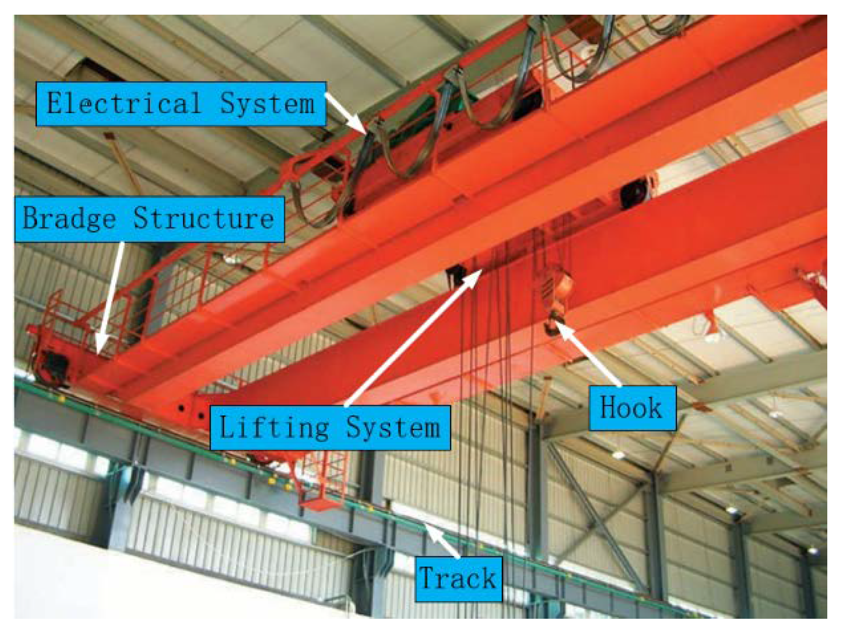
(1) Bridge structure: bearing the weight of the lifting trolley, composed of end beams, main beams, railings, walking platforms, tracks, and cabs.
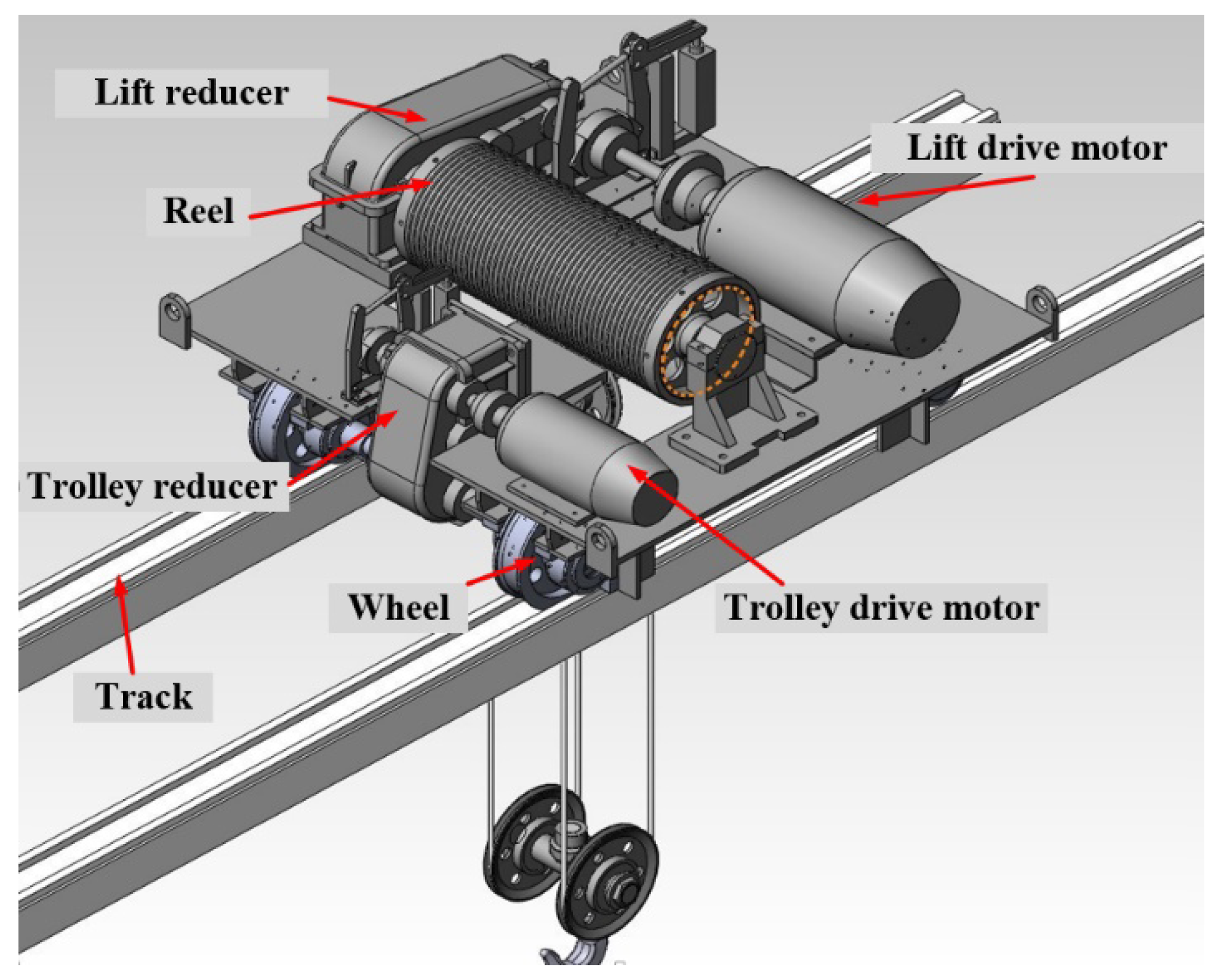
(2) Operating mechanism: The operating mechanism is subdivided into a large trolley operating mechanism and a small trolley operating mechanism, which drive the wheels of the crane and the trolley respectively to run along their respective tracks to complete the specified movement (Fig.2 is the mechanism diagram of the trolley).
Figure 2.
Three-dimensional model of bridge crane trolley mechanism.
(3) Lifting mechanism: The function of the lifting mechanism is to realize the lifting movement of materials, which is mainly composed of motor, pulley block, steel wire rope, braking device and other corresponding safety devices.
(4) Electrical device: The electrical system of the bridge crane includes electrical equipment and electrical wiring. It is composed of power supply device, protection box, lighting equipment, electrical circuit, electrical main circuit, lighting signal circuit and control circuit, etc.
2.2. The Workflow of the Bridge Crane
Under normal circumstances, the main workflow of a complete lifting process is:(1) The lifting process of the load, that is, lifting the hoisting weight to a specified height for the next step of transportation,(2) Carry the hoisting load to the front or above the target position by the movement of the trolley,(3) Drop the hoisting weight vertically from above the target position to end this working stroke. In the actual work process, the above three steps are carried out in sequence.
There are two main reasons that cause the crane to sway during the working process: The first reason of the swing of the lifting weight is caused by the acceleration and deceleration movement of the crane's large and small trolley operating mechanism and the main and auxiliary lifting mechanisms during the working process. The second reason of the swing is caused by some uncertain factors in the operation process, such as the wind load received by the crane during the operation, the operation error of the operator, the height difference of the track, etc. In this paper, the different swing factors of the crane that cause the swing are analyzed, and the mathematical model of its swing angle is build.
2.2.1. Load Analysis of Crane during Lifting Stage
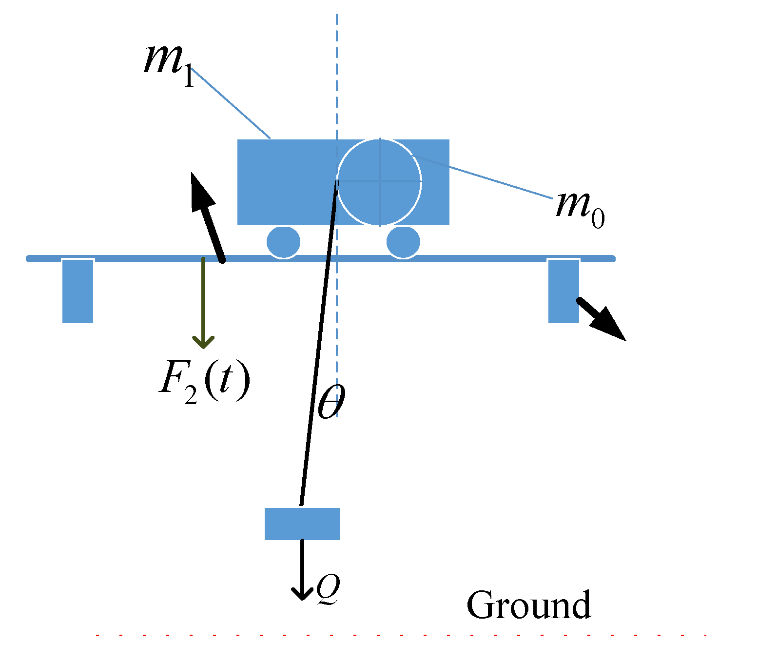
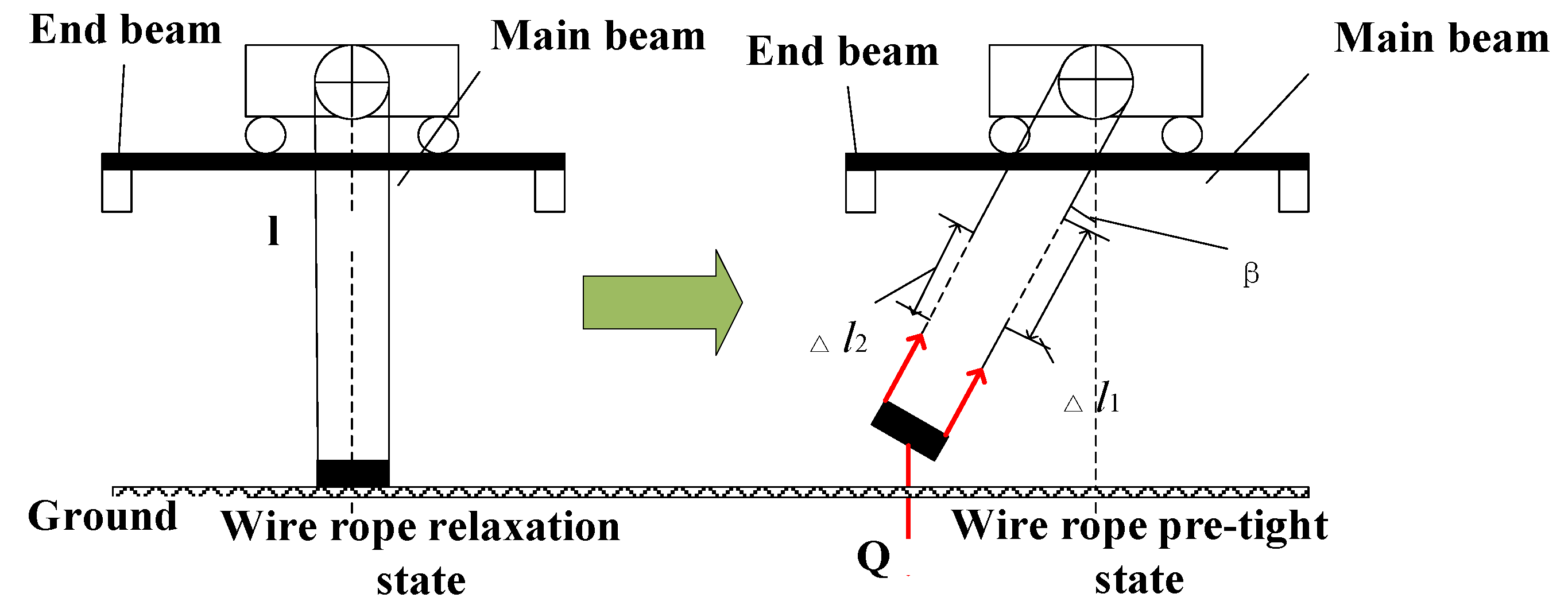
According to the working conditions of the crane, the lifting process is divided into three stages: In the first stage, before the lifting mechanism is started, the wire rope is in a relaxed state. At the moment when the lifting mechanism is started, the wire rope changes from slack to straightened. If the weight of the wire rope is ignored at this time, the wire rope is not stressed and the lifting weight Q is equivalent to being at a standstill. In the second stage, the force of the wire rope is from 0 to , the lifting wire rope is gradually increased from the unstressed state to the tension, and the force is applied to the bridge through the drum and its supporting members, which indirectly causes the force on the bridge to gradually increase, but the lifting objects are still not off the ground (as shown in Fig.3). is trolley quality, is reel quality.
Figure 3.
Working conditions after lifting heavy objects off the ground.
The third stage after the load is lifted off the ground. The hoisting weight starts to leave the ground and resonates with the structure. At this time, the force of the wire rope reaches the maximum, and the dynamic load generated by the hoisting mechanism is also the maximum. Due to the different resistance of each pulley in the pulley block, the pulling force generated by the hoisting cannot be evenly distributed to each rope, resulting in uneven rope tension, making the system a weak damping system, and causing a slight load swing. Due to the existence of the initial swing, the acceleration movement of the large and small trolley will make the swing more violent, so the vibration swing angle is generated[6].
2.2.2. Load Analysis of Large (Small) Trolley of the Cranes during Acceleration
After the crane hoisting mechanism lifts the load, the load needs to be hoisted in front of or above the target position, at this time, the crane and its wheels and other structures are subjected to horizontal loads. In the actual operation of the crane, the large and small trolley usually move separately, even in the case of the large and small trolley are linked, the law of motion in the linkage direction is the same as that of the trolley alone, therefore, the motion of the big trolley is separately considered in the load analysis. The main load of the crane in the horizontal direction along the track is:
(1) Horizontal inertia The horizontal inertia force of the trolley movement is the inertia force along the rail direction generated by the crane's own weight and lifting heavy objects when the trolley operating mechanism is started or braked, which includs the inertia force of the whole machine and Inertia force of small trolley with lifting weight .
(2) The rolling friction of the track to the wheels and the structural resistance of the crane's rotating mechanismconstitute the total walking resistance of the wheels on both sides [11]:
where: :bearing friction factor of rotating mechanism, : wheel axle diameter of large trolley, :diameter of wheel tread of the large trolley, :rolling friction coefficient,: Wheel pressure.
(3) Horizontal lateral force when the crane moves obliquely The existence of the track height difference of the bridge crane will lead to the occurrence of the phenomenon of rail gnawing and the running lateral force acting along the axial direction of the wheel, which will cause the crane to be worn to different degrees. The track of the bridge crane (travel) is in use due to the crane The displacement, settlement and deformation of the beams cause the unevenness of the driving track. There are many reasons for the height difference of the crane track. The most common one is that the crane's service life is too long, which leads to the displacement, settlement and deformation of the crane track. In addition, there are certain tolerances for wheel manufacturing quality and installation. The friction between the rim of the wheel and the side of the track causes additional resistance , intermittent swings of the lifting weight will be produced. According to the "Crane Design Code" [12], the formula for solving the deflection lateral force of the crane is:
Whereadditional friction resistance coefficient,:the maximum total wheel pressure on the side of the crane subjected to the deflection lateral force,: deflection lateral force coefficient.
(4) Wind load of direction The crane is exposed to wind load during outdoor operation, the wind load is related to the windward area of the crane. Therefore, when constructing the swing model of the crane during the movement, according to the operating environment of the crane, the influence of the load deflection caused by the wind load must be considered[13].
Where,wind pressure calculated,windward area of the crane,:the shape factor of the lifting weight in the wind direction,Wind pressure height change coefficient.
3. Dynamic Analysis and Mathematical Model Construction of Crane Motion System
3.1. Kinematics Analysis of Crane in a Working Cycle
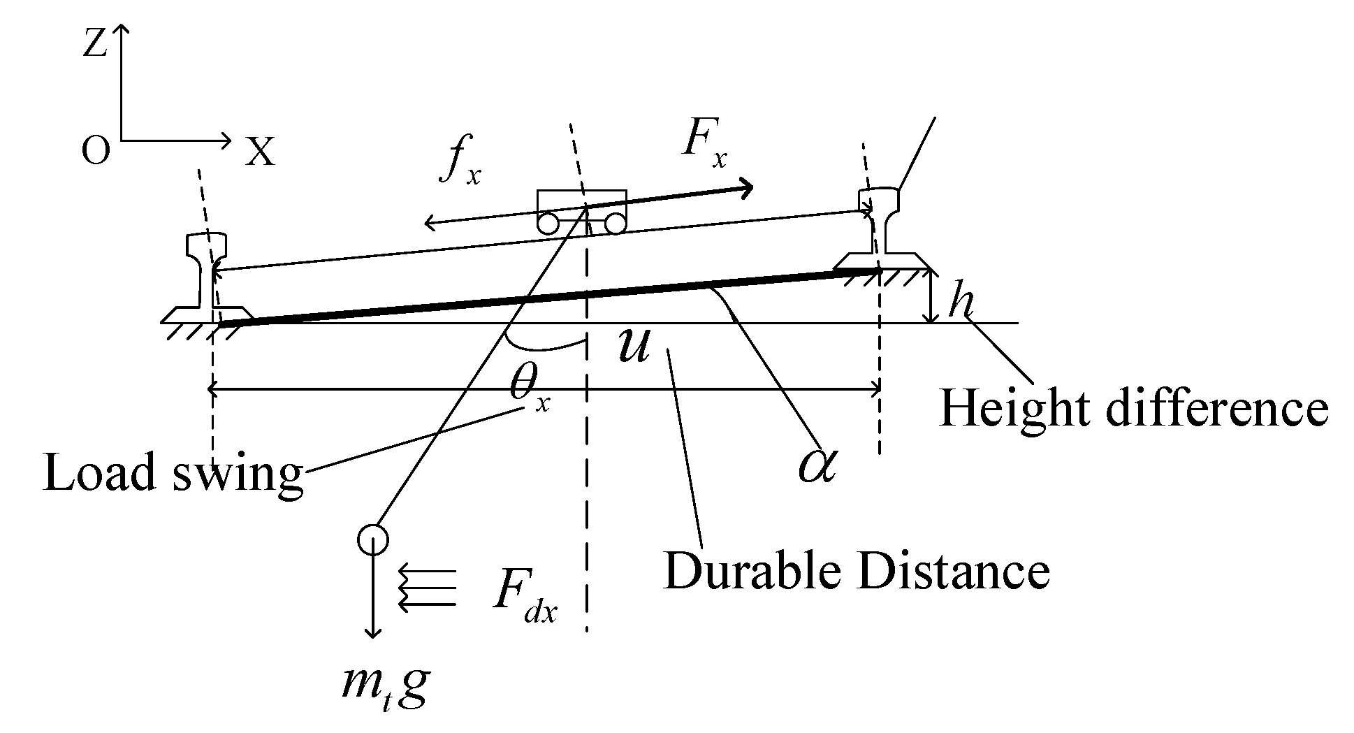
In Fig.4, there is the swing diagram of the lifting weight under the horizontal load when the crane is moving (in the Cartesian three-dimensional coordinate system), it can be seen from the figure that when the crane is working, the heavy object will swing through the rope to the suspension point of the trolley, the swing angle is .Analyze the swing angle along the crane's forward direction and the horizontal movement direction of the heavy object on the bridge, and projected to planes and respectively to getand,and are the driving forces that drive the movement of large and small trolley respectively, andare the frictional resistance of large and small trolley respectively, andare the acceleration of the large and small trolley along the running direction respectively,andrepresent the corresponding displacement in theanddirections,is mass of lifting weight, and are the equivalent masses of the trolley bridge structure (including the platform, main beam, end beam, the structure of the small trolley, etc.) and the mass of the small trolley,is the wind load imposed on the lifting weight. Due to the difference in height of the track, the upper surfaces of the two tracks are not in the same plane, and there is an angle between the trolley body and the horizontal plane.
Figure 4.
The motion model diagram of the crane in a working cycle.
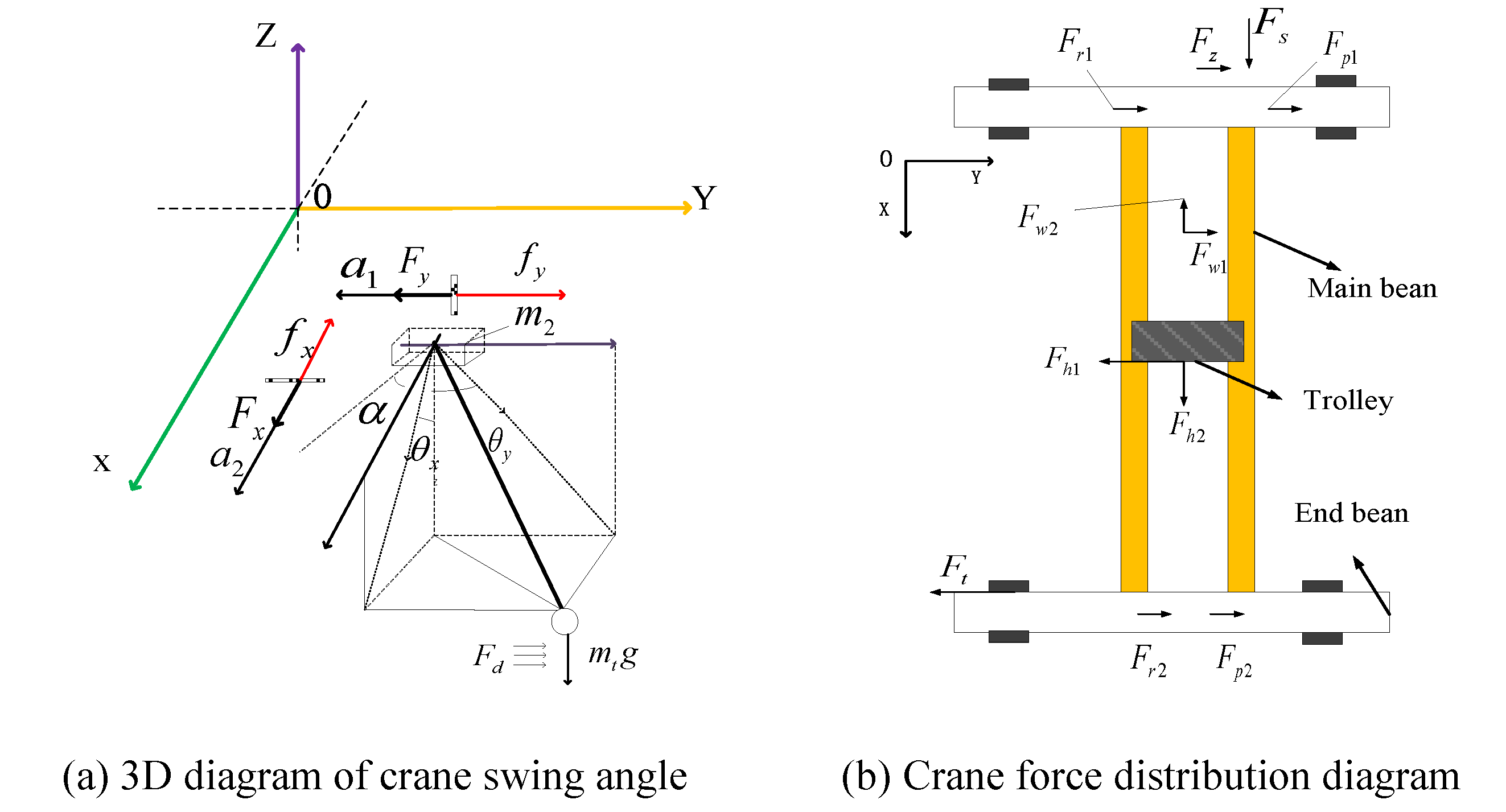
(a) 3D diagram of crane swing angle
(b) Crane force distribution diagram
According to existing research [14], when a complete operation cycle is carried out, the trajectory of the lifting weight is similar to a circular swinging motion on a spherical surface. The swing angle of the lifting weight can be decomposed into the swing angle generated by the large and small trolley moving in a two-dimensional plane. Therefore, the three-dimensional swing angle model of the bridge crane can be regarded as the swing angle formed by the large and small trolley in the moving direction when they move separately, then the independent two-dimensional motion equations are obtained in the x-axis direction and the y-axis direction respectively. To simplify model construction, the following assumptions need to be made:
(1) The movement processes of the big and small trolley are independent of each other.
(2) The elastic deformation of the bridge crane structure is ignored.
(3) The friction between the wheel of the trolley and the track of the trolley is ideal rolling friction, and the friction coefficient is constant.
(4) The steel rope is regarded as a qualities sling, and the friction between it and the pulley and drum of the trolley hoisting mechanism is ignored.
(5) The wire rope is ideally wound on the drum groove and pulley, and does not slip during lifting or lowering.
(6) The additional resistance caused by the two tracks being not in the same plane is incorporated into the wheel rolling friction.
(7) and are completely affected by the output of the inverter, and some non-linear factors such as reducer and trolley motor is ignored
3.2. Construction of the Mathematical Model of the Swing Angle in the
Direction during the Working Process of the Crane
(1) The initial swing angle of the lifting weight during the lifting phase
Many scholars treat the wire rope as a rigid body when studying the lifting mechanism of a crane, simplifying the calculation of the wire rope. In fact, the wire rope is an elastic body, and the wire rope will be elastically deformed under the action of the lifting weight. Let the weight of the lifting weight received by the wire rope be , let and be the elastic elongation of the left and right wire ropes under tensile load (unit: mm), according to Hooke's law: the load value of each wire rope is,( is the stiffness coefficient of the wire rope) [15]. Assuming that there are n sets of steel wire ropes passing through the pulley block, and the force analysis on the hoisting weight is carried out(Fig.5), then:
Figure 5.
Schematic diagram of swing angle during lifting.
The length of the rope has the following relationship with The length of the rope has the following relationship with the weight of the weight.
where, is the maximum static tension of the wire rope wound into the drum (for the convenience of calculation, it is assumed that each steel wire bears the same tensile force and is the maximum tension.). the sum of the lifting load and the weight of the spreader, is the pulley block magnification. is maximum tension in the specified pulley group ratio. is the efficiency of the pulley block (available by referring to the manual). is the equivalent elastic modulus of steel wire rope, is the cross-sectional area of the wire rope. is the total length of the wire rope. is Full length of the wire rope below the reel without force. Therefore, the initial swing angle of the hoisting wire rope can be obtained as:
(2) When the large trolley is moving in the direction
When the large trolley is moving in the direction and the wind load is affected, the working conditions are as follows: the small trolley is located in the middle of the main girder, the hoisting weight is off the ground, and the full load is suspended on the small trolley. The lifting mechanism and the running mechanism of the trolley are stationary, and the large trolley completes the movement process of starting, accelerating, running at a constant speed and braking. The load analysis is shown in Fig.6.
Figure 6.
Force diagram of large trolley operating mechanism.
The three-dimensional dynamics analysis of the crane movement process is carried out, and the coordinate system is constructed with the large trolley displacement direction (left is the positive direction) as the direction, and the dynamic differential equation of the large trolley system during the movement process is obtained.
where, : large trolley quality, large trolley driving force, : the friction between the wheel set of the large trolley and the guide rail, :additional resistance.
Take lifting heavy objects as the research object for analysis.
where, :during the movement of the large trolley, : wind load of direction, the angle between the lifting weight and the trolley direction, from equations (11) and (12), we can get:
where, the friction forcebetween the wheel set of the large trolley and the track can be expressed as formula (14).
where, is the coefficient of dynamic friction between the wheel set of the large trolley and the track, then (13) can be calculated as:
According to the load analysis of the lifting weight in the vertical direction:
According to formula (4), (5), (6) and (16), then formula (17) is gotten:
After finishing formula (18), formula (19) is gotten:
In summary, the swing angle in the direction is:
Substituting equations (9) and (19) into equation (20), formula (21) is gotten.
3.3. Construction of the Mathematical Model of the Swing Angle in the
Direction during the Working Process of the Crane
There is a track angle when the large trolley is moving and the upper surface of the double track is uneven.
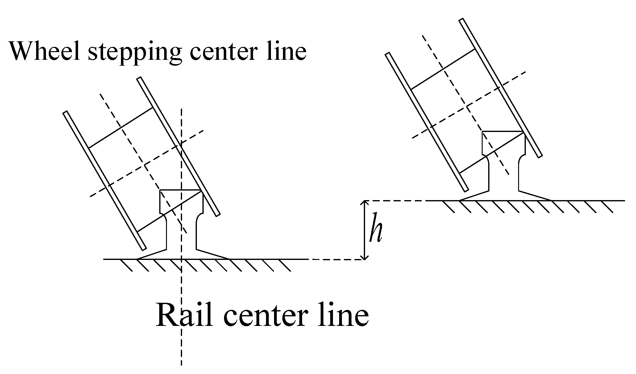
The deformation and tilt of the track will be inevitably occurred during the installation and long-term operation of the bridge crane. According to the requirements of "Bridge and Gantry Crane Manufacturing and Track Installation Tolerance", when the height difference between the tracks exceeds , lateral slippage will be occurred due to the load, and the horizontal force on the running mechanism will change, which the load swing will be aggravated. The schematic diagram of the track height difference is shown in Fig.7.
Figure 7.
Schematic diagram of track height difference.
Load analysis diagram constructed according to Fig.8, because the two rails of the large trolley are not in the same plane, an inclination angle will be generated, and the additional resistance generated is unified into the wheel rolling friction. It can be seen from the structural analysis, , at this time, The existence of this included angle will cause a certain slope to the track of the trolley. The force analysis of the trolley is shown in Fig.9.
Figure 8.
Schematic diagram of track height difference.
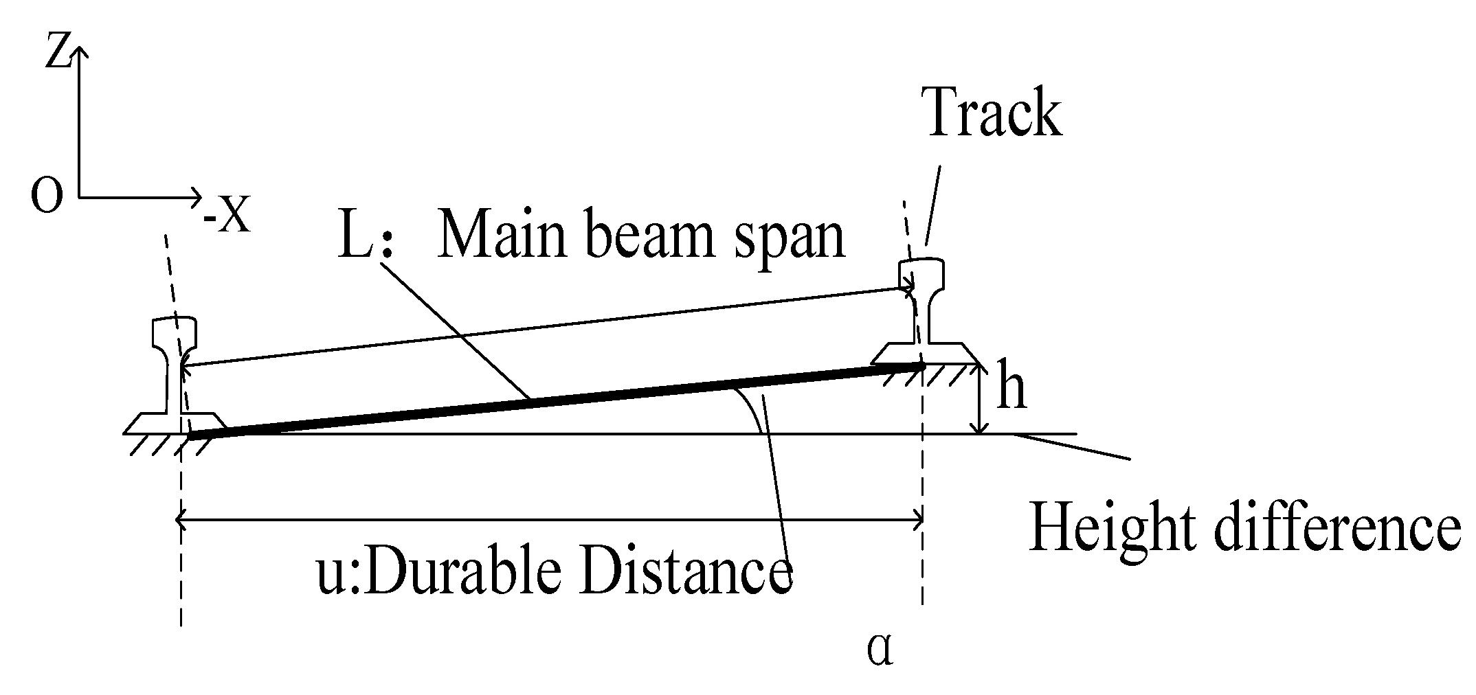
Figure 9.
Force diagram of small trolley operating mechanism.
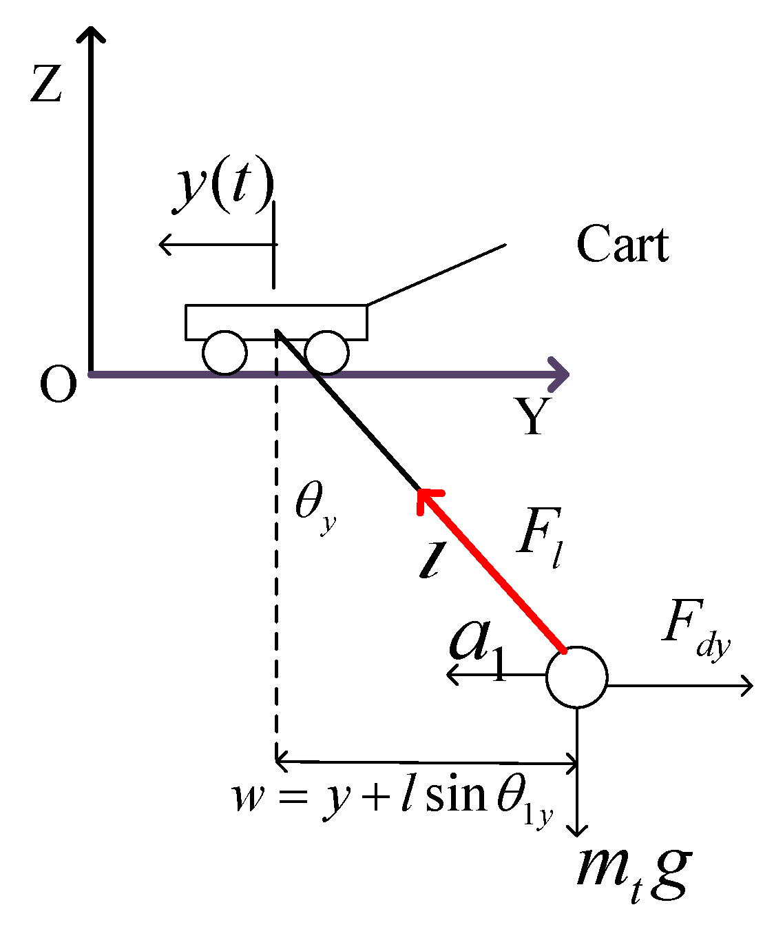
From this, the dynamic differential equation of the crane small trolley system in the movement process is:
where,: the mass of small trolley, the driving force of the small trolley, :the friction between the wheel set of the small trolley and the guide rail, :the wind load of x direction.
Analyze the lifting weight as the research object:
where, :the wind load, generally, :is in the range of , when ,, according to formula (25),formula (26) is gotten.
According to the load analysis of the lifting weight in the vertical direction:
The swing angle component of the crane in the direction is:
In summary, the comprehensive swing angle of the crane is:
Substituting equations (21) and (28) into equation (29), equation (31) is gotten.
4. Three-Dimensional Simulation Model of Swing Angle of Lifting Weight
Normally, for the mathematical model of the swing angle of the lifting weight, simulink needs to be used for simulation analysis to determine the degree of influence of each influencing factor on the swing angle of the lifting weight, and provide analysis conclusions for the subsequent anti-sway control.
In this paper, a standard crane QD−5T−22.5m−ASW is selected as the simulation object, according to the standard, the selected type of steel wire rope is , and relevant parameters is obtained through crane design specifications GB/T3811-2008. According to the "Crane Design Specification", when the load is high, the height is 10 meters,. the wind load expression is, and other calculation parameters are shown in Table 1.
According to formula (30), making,, and the functional formula (Formula 32) of the Simulation module is established.
5. Analysis of Influencing Factors of Swing Angle of Lifting Weight
5.1. The Influence of the Driving Force on the Swing Angle
As shown in Fig.10, driving force variation curve over time, and its amplitude has reached 3000N. Under the condition that other simulation parameters remain unchanged, the swing angle-time curve of the same driving force under different acting time is obtained in , is linear increase, in , the driving force remains the same, in , the driving force is linearly decreasing. Assuming no interference wind load, simulation gets the graph shown in Fig.11.
Figure 10.
The waveform of the driving force of the crane in the
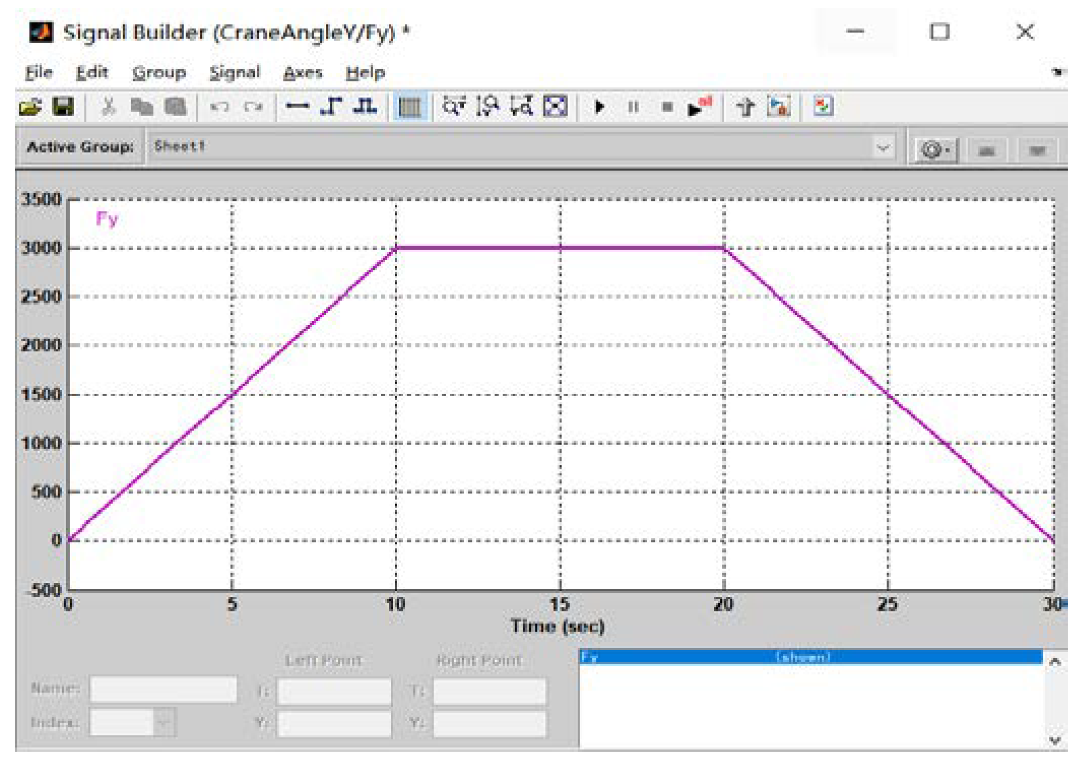
Figure 11.
Lifting weight swing angle-time curve under different driving time.
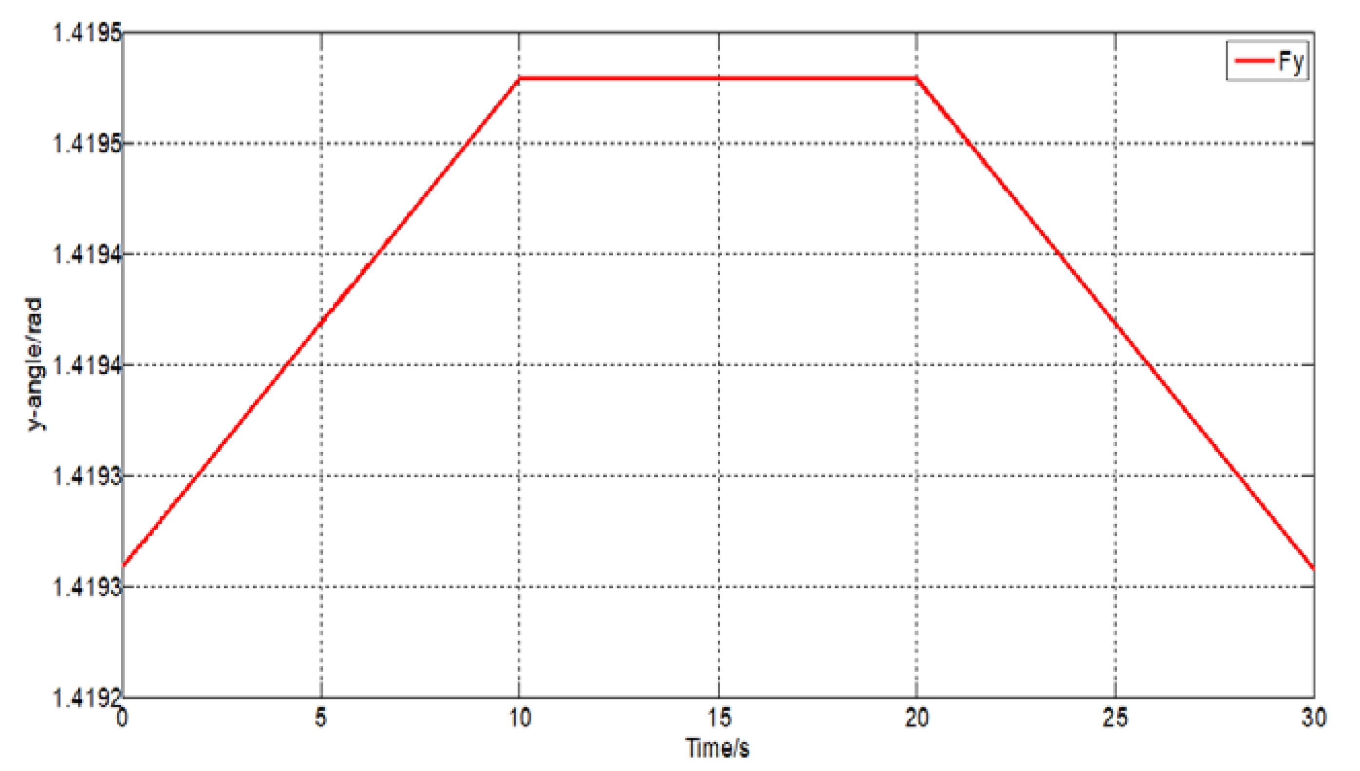
It can be seen that the increased driving force has a certain promotion of the crane swings. Even if the driving force is reduced, due to the inertial effect, swing angle is not promptly reduced to 0. According to Fig.12, it can be concluded that the change in the driver of the crane is consistent with the load angle. It can be seen that the size of the driving force will affect the swing angle of the hoist, and the swing angle increases with the increase of the driving force.
This gives us a revelation: according to the load swing angular signal, the crane outputs the appropriate driving force, thereby achieving the effect of eliminating the load swing.
direction of the large trolley changes with time.
5.2. The Influence of Wind Load on Swing Angle
In the process of working on the bridge crane, the existence of wind-in contraction will inevitably affect the load swing. According to the relevant literature, the bridge crane needs to stop the operation when the wind reaches 6th. In order to study the influence of the wind storage size, this experiment has studied the swing of the crane under the wind speed of , and obtains swing angle-wind speed graph(shown in Fig.12).
Figure 12.
Swing angle diagram of lifting weight varies with wind speed.
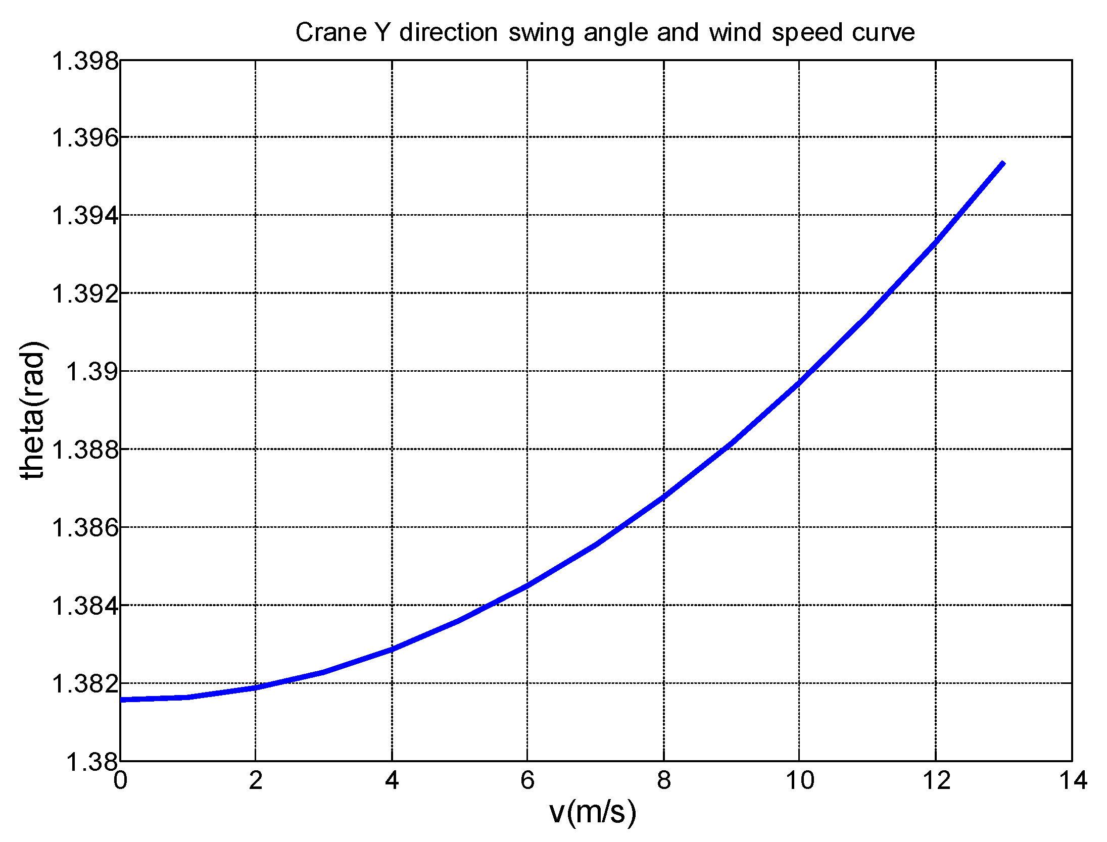
As can be seen from the figure, when the wind speed is 0-4 m/s, the swing angle increase is relatively slow, after 4 m/s, the swing angle increases with the wind speed, and the angle growth is also rising, which is due to inertia and wind speed. The double effect is caused, so that it is understood that the impact of wind stall on the lift of the crane is not negligible.
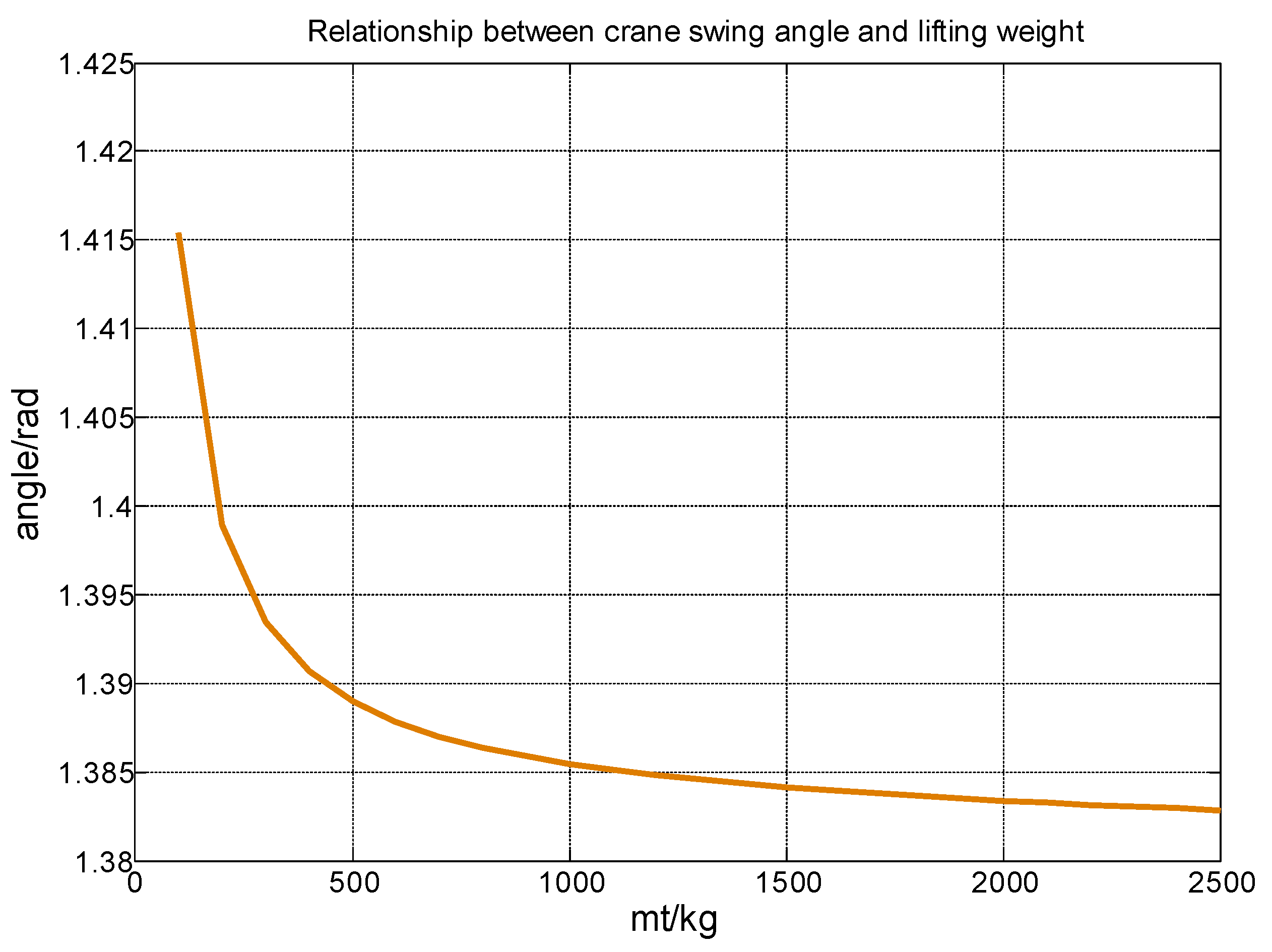
5.3. The Influence of Lifting Weight Quality on Swing Angle
In response to the effect of hoisting quality on the hanging rocking, the simulation conditions include other parameters, the driving force is 3000N, and the wind speed is 4m/s. Simulation analysis of the model is obtained to get the relationship between the angle of hoisting and the weight. As can be seen from Fig. 13, as the heating mass increases, the smaller the hanging rocking angle, the initial hoist quality is the smallest, and its swing angle is the largest, because when the driving force F is fixed, the smaller the height mass M, then The larger the acceleration A, the smaller the swing angle of the hoisting. This can be obtained, and the quality of the hoisting is affected under certain conditions.
Figure 13.
Swing angle diagram of lifting weight varies with weight.
6. Research on Anti Sway Control Technology of Bridge Crane
6.1. Swing Angle Detection during Crane Operation
In this study, Kienz LS-5041 laser scanner is used to measure the swing angle of the crane during operation[16]( As shown in Figure 14). The laser scanner can be connected to four scanning heads with a resolution of and a maximum scanning range of .Two groups of laser scanners are installed in the square bracket at the bottom of the crane trolley bridge, and the wire rope passes through the center point O of the optical plane when it does not swing. The scanning range of the two groups of laser scanners is the optical plane (as shown in Figure 14). The coordinates of the intersection of the wire rope and the plane are the key data for detection. The coordinates and the distance from the wire rope connection point to the optical plane form the spatial coordinates, then the algebraic expression of swing angle is obtained indirectly through geometric relationship calculation. is the included angle between the wire rope and the centerline as shown in Figure 14.
As shown in Figure 15, direction that from group A laser scanning transmitter to receiver is the trolley moving direction, direction from group B laser scanning transmitter to receiver is the crane moving direction, if the crane swings, two sets of laser scanners can detect the coordinate at the intersection of the swinging wire rope and the plane.
Get the coordinates and the distance from the top of the crane wire rope to the plane, and then the crane swing angle is calculated through the geometric relationship.
where,is the -direction swing angle of the crane, and is the -direction swing angle of the crane.
The swing angle of the crane during operation is detected by laser detection technology. The acquired swing angle signal is processed and input to the anti swing control system of the crane. The anti swing control system of the crane conducts comprehensive processing in combination with the displacement, speed and measured swing angle of large and small trolleys, and then feeds back to the crane control system through closed-loop feedback, so as to control the operation of the crane operating mechanism and lifting mechanism, and finally achieve anti swing control.
6.2. Design of Anti Sway Controller for Bridge Crane
6.2.1. Design of Conventional PID Anti Sway Controller for Bridge Crane
PID (Proportional, Integral, Differential) control technology is the most mature and widely used closed-loop feedback control technology. The control principle is as follows: Let the given input value and the actual output value of the mechanical system to form a deviation , take this deviation as the feedback input of the controller, and obtain the output control variable through the proportional integral differential logic operation. The general form of PID controller control quantity is [16]:
where, is a proportional control parameter, is the integral control parameter, is differential control parameter, is a deviation.
The performance of the PID anti sway controller mainly depends on the reasonable adjustment of the three parameters、 and . The three parameters of the PID controller play different roles in different time periods. To increase the proportion coefficient that the response speed is conducived to increase, but too large the overshoot is increased too. To increase the integral coefficient that the overshoot is reduced to a certain extent, but the static error elimination time will be prolonged. To increase differential parameters that the system can be made more stable, but the anti-interference ability will be weakened. The PID control parameters are determined according to critical curve method [17], at first, a larger scale coefficientis selected and the value of the scale coefficient is gradually reduced, when the output curve reaches constant amplitude oscillation, then the critical oscillation scale coefficient and critical oscillation period are recorded. The calculation formula is seen in Table 2.
According to the crane swing angle model, a PID controller is designed to control the crane displacement and swing angle. The control schematic diagram is shown in Figure 16.
The initial swing angle is assumed 0, the crane mass is 10T, the load mass is 5T, the rope length is 3m, g is 9.8m/s, and the friction coefficient is 0.2, for the above model, then the three parameter values 、、 are calculated by the critical curve method. When , the swing angle output curve can be achieved approximately constant amplitude oscillation (as shown in Figure 17), according to Table 2, then the three coefficients of the swing angle PID controller are calculated as,,.
Figure 18 shows the swing angle curve of the bridge crane under the control of the conventional PID anti swing controller. When the initial swing angle is 0, the crane will swing gradually under the action of the driving force, the PID anti swing controller can control the maximum swing angle below, and finally the swing angle can be controlled to zero.
6.2.2. Design of Fuzzy Anti Sway Controller for Bridge Crane
With the continuous improvement of production requirements, there are also high requirements for control accuracy, response speed and stability of control technology. The main advantage of fuzzy control is that when the system model data is inaccurate, only the controlled object data and expert experience need to be converted into "fuzzy rules" that can be processed by the computer to achieve intelligent control [17]. The crane anti sway fuzzy controller is consisted of six parts: control variables, knowledge base, fuzzy processing, fuzzy rules, fuzzy reasoning and non fuzzy. Its control principle is shown in Figure 19
Based on the research of conventional PID anti sway controller, the fuzzy algorithm is used to optimize the PID parameters. The input of the fuzzy controller isand, and the output is the modified value of the PID controller parameters,and. The design process of fuzzy PID controller is:
① Determine the dimension of anti sway fuzzy controller. In this design, two-dimensional input is selected, swing angle deviation and deviation rate are selected as input variables, and output variables are the three parameter correction values of PID controller: ,and.
② Two domains of variables is determined: the basic domain is the actual range of deviation and deviation change rate , the fuzzy universe is that the fuzzy controller can identify the actual variation range of the input signal, and finally the quantization factor and scale factor are calculated.
③ Fuzzy subsets is defined: Determine the number of each fuzzy subset and the fuzzy language, and to select the appropriate membership function for each fuzzy subset
④ Constructing output fuzzy control rule table under input variables.
⑤ According to the input quantity in (1) and the fuzzy rule in (3), the outputs of the fuzzy controller are,and. Then the initial parameters of the conventional PID controller and the output values of the fuzzy controller are linearly added to obtain the control quantity of the anti sway control system of the bridge crane.
⑥ To convert the fuzzy variables of the fuzzy universe to the clear values of the basic universe.
(1) Determination of basic parameters of fuzzy controller
The basic parameters of the fuzzy PID controller include the basic universe of language variables, swing angle and swing angle acceleration, the basic universe of cart displacement and displacement acceleration. In the process of justification, it is necessary to calculate the quantization factor and scale factor of variables. The quantization factor corresponds to the input of the controller and the scale factor corresponds to the output of the controller. The basic scope of deviation is, the basic universe of deviation change rate is, the basic universe of control quantity is. Let the upper bound of the universe of the three fuzzy subsets be, and , quantification factor can be calculated: ,. The scale factor [18] is calculated by. Then the basic domain of load swing angle is[-1.5,1.5], the basic universe of other variables as well as scale factors and quantification factors are shown in Table 3.
(2) Membership function and fuzzy rules of anti sway fuzzy controller
The number of input variables of the fuzzy controller determines the control effect. Theory shows that the more the number of input variables of the fuzzy controller is, the more accurate the control effect will be, but it will increase the complexity of the model and the calculation time. Under the condition that the control effect is accurate and the calculation time is moderate, seven subsets are selected to represent the output and input of the fuzzy controller, they are respectively: {negative big, negative middle, negative small, zero, positive small, positive middle, positive big}, it is described in fuzzy language as: {,,,,,,}. An appropriate membership function is selected for each subset, which represents the compliance of input variables with fuzzy rules. One of the rule statements is: If e is and is , Thenis , is, andis . According to expert experience, a set of control rules with good performance is shown in Table 4.
The fuzzy quantity is obtained through fuzzy reasoning, and the accurate value is obtained after the area center method (Centroid) is used for de fuzzy processing. The de fuzzy calculation is:
where, represents proportional, integral and differential parameters,if ,then represents the value of x at time,represents the value of x at time, corresponds to control rules. The integral and differential parameters are deduced by analogy, and the parameter increments , and are substituted into Formula (35)[19] to obtain the actual PID controller parameters after fuzzy processing.
where, 、、 is initial values of,and respectively, ,and respectively represent the modified values of the three parameters by the fuzzy controller.
6.3. Simulation of Fuzzy PID Control System for Anti Sway of Bridge Crane
6.3.1. Simulation Analysis Model of Fuzzy PID Anti Sway Controller for Bridge Crane
Figure 20 shows the simulation model of anti sway fuzzy PID controller of bridge crane.
In the fuzzy PID controller of the swing angle, the gain module,are the quantization factors of the swing angle and its acceleration respectively, angle and are the actual output angle and displacement of the bridge crane model.,and are the scale factor of the three parameter, ,and are respectively the three control parameter values of the swing angle PID controller, they are the initial value of ,and. The internal structure of the swing angle fuzzy controller is shown in Figure 21.
6.3.2. Simulation of Anti Sway Effect of Fuzzy PID Controller
Figure 22 shows the curve of swing angle with time under the control of anti sway fuzzy controller.
From the simulation results, it can be concluded that the maximum swing angle of the bridge crane is, and the swing angle amplitude gradually decreases with time, and the swing angle is eliminated to 0 after 11s. According to the measured data at the crane working site, without any anti sway measures, the swing angle should be about, and the swing angle continues to oscillate. Therefore, the fuzzy PID anti sway controller can achieve good anti sway control.
6.3.3. Simulation of Swing Angle under Different Rope Lengths and Load Masses
In order to verify the anti sway positioning effect of the fuzzy PID anti sway controller when the wire rope length changes, three groups of rope length parameters are set up on the basis of ensuring that other parameters remain unchanged: , and.The anti sway simulation test results are shown in Figure 23. It can be seen from the figure that before the swing angle reaches the first amplitude, the shorter the wire rope length is, the greater the load swing amplitude is. After t=5s, the shorter the rope length is, the faster the load swing angle drops. This shows that the fuzzy PID anti swing controller has a faster anti swing positioning effect for the load swing under the condition of short rope length, and the fuzzy PID anti swing controller has a better adaptability for the load swing under different rope lengths.
Figure 24 shows the swing angle curve under different load masses. Set three groups of load mass test parameters as: ,and . It can be seen from Figure 24, after the load mass changes, the larger the mass is, the smaller the swing angle amplitude is, and the swing angle change trend is basically consistent with that before the increase. Therefore, when the binding force is constant, the smaller the mass is, the greater the swing acceleration is, and the swing will be more intense.
6.4. Comparison of Simulation Results between Conventional PID Anti Sway Controller and Fuzzy PID Controller
The comparative analysis of swing angle curve under the control of conventional PID anti sway controller and fuzzy PID controller is shown in Figure 25, when , the swing angle of the crane under the conventional PID control reached the first peak , then the peak value of the swing angle gradually decreases until it becomes stable to 0. Under the action of the fuzzy PID controller, the peak value of the first swing angle of the crane load is, after , the swing angle basically tends to zero and there is no oscillation, which is 2s ahead of the conventional PID algorithm. The research results show that the fuzzy PID controller can restrain the swing of the crane quickly and reduce the time for the swing angle to stabilize.
From the analysis of engineering application, it can be seen that the fuzzy PID anti sway controller can shorten the anti sway time of the crane, thereby improving the operating efficiency to a certain extent and ensuring the safety of hoisting. The analysis of the experimental results shows that compared with the conventional PID anti sway controller, the fuzzy PID controller can not only weaken the external environmental interference, but also quickly eliminate the swing, with low overshoot, strong adaptability and other advantages.
7. Conclusion
According to a working cycle of a bridge crane, a three-dimensional model of the crane is established, the dynamic behavior of its movement process is analyzed, and two movements direction of a large and small trolleys are divided into according to the spatial state of the swing angle of the lifting weight during the movement of the crane, and the mathematical model is constructed and the simulation analysis of the component is done.
According to Newton’s second law, a mathematical model of the swing angle is constructed by comprehensively considering the influence of the lifting weight, the double-track angle of the trolley and the wind load on the lifting weight. These factors are simulated, and the corresponding curves of the swing angle change with time or these factors are obtained. According to the results of the study, the initial swing angle can not be ignored, the acceleration and deceleration of the crane will increase the swing amplitude of the lifting weight, the presence and speed of wind load have a significant impact on the swing of the lifting weight. The research results can provide a theoretical research basis for the subsequent research on crane anti-sway, and provide a theoretical basis for improving the work efficiency and safety of the crane.
Finally, according to the swing angle model of the bridge crane in the working process, the control target is proposed, and the conventional PID anti sway control technology and fuzzy PID anti sway control technology are studied and simulated. The research results show that: because the conventional PID controller cannot adjust the parameters in real time according to the system parameter changes, facing the specific nonlinear and time-varying model of the bridge crane, the conventional anti sway PID controller can not eliminate the load swing in a smaller time range, which has limitations, but the fuzzy PID controller can accurately locate and effectively control the swing angle of the lifting load, and its anti sway effect is better than the conventional PID controller.
Acknowledgments
This research is supported funded by Natural Science Fund of Hubei Province [Grant No. 2016CFB581], Teaching Research Project of Wuhan University of Science and Technology (Yjg202008) and (2020X042), Cooperation Project of Wuhan Special Equipment Supervision and Inspection Institute (2022H20344) and Open Project Fund of Chemical Equipment Strengthening and Intrinsic Safety Hubei Provincial Key Laboratory.
Conflicts of Interest
The authors declare no conflicts of interest.
References
- Xu, X.-x. Research on anti-sway technology of bridge crane based on new control concept. TaiYuan University of Science and Technology, TaiYuan, China, 2020.
- Gao, C.-l. Design and research of anti-sway control system for bridge crane. Southwest Jiaotong University, Chengdu, China, 2019.
- Zhang M, Ma X, Rong X, et al. A novel energy-coupling-based control method for double-pendulum overhead cranes with initial control force constraint. Advances in Mechanical Engineering 2018, 10, 168781401775221. [Google Scholar] [CrossRef]
- Ramli L, Mohamed Z, Jaafar HI. A neural network-base-d input shaping for swing suppression of an overhead crane under payload hoisting and mass variations. Mechanical Systems and Signal Processing 2018, 107, 484–501. [Google Scholar] [CrossRef]
- Fan Bo, Zhang Wei-wei, Liao Zhi-ming. Positioning and Swi-ng Control of Bridge Crane Based on Load Energy Coupling. Control Engineering 2020, 27, 2077–2083. [Google Scholar]
- Pang Zhen-hua,Liu Fang,Tang Yu,etal. Research on the coupling of speed and swing angle of gantry crane. Manufacturing Automation 2021, 43, 138–142. [Google Scholar]
- 7. Wu Q, Wang X, Hua L, et al. Modeling and nonlinear sliding mode controls of double pendulum cranes considering distributed mass beams, varying roped length and external disturbances. Mechanical Systems and Signal Processing, 2021; 158.
- Liu Lei, Yang Guo-lai. Analysis of Lateral Vibration of a Class of Variable Section Beam Acted by Moving Mass. Engineering Mechanics 2015, 32, 212–219. [Google Scholar]
- Zhou Qi-cai, Wang Lu, Xiong Xiao-lei, etal. Research on M-athematical Modeling Method of Overhead Crane Anti-sway Control System Considering Elastic Structure. Manufacturing Automation 2017, 39, 20–22+35. [Google Scholar]
- Yang Zong-yu. Dynamic Modeling and Simulation of Lifti-ng System of Bridge Crane. Wuhan University of Technology, Wuhan, Chian, 2018.
- 11. Yang Qing, Ji San-you, Jiang Zheng. Analysis and calculate-ion of skew operation of gantry crane. Lifting and Transporting Machinery, 2020; 47–52.
- National Standard GB/T3811-2008 "Crane Design Specifi-cation". BeiJing, Beijing Hoisting and Conveying Machinery Design and Research Institute 2012, 1, 1.
- 13. Yan Zi-mian. Crane wind load calculation problem-calcula-tion of wind pressure (part 1). Refrigeration and Air Conditioning and Electrical Machinery, 1981; 22–25.
- Liyana Ramli,Z. Mohamed,Auwalu M. Abdullahi,H.I. Jaafar,Izzuddin M. Lazim.Control strategies for crane systems: A c-omprehensive review. Mechanical systems and signal proc-essing 2017, 95, 1–23. [Google Scholar]
- 15. Yuan Xu-cheng, Li Xiang-dong. Wireless sensor network for real-time monitoring of the force status of crane wire ropes. Heavy Machine, 2014; 72–74.
- LU Feng-jiao, LIU Hai-jiang, YOU Lei. Overview of Anti sway Control Algorithm for Bridge Crane. Journal of Ship and Ocean Engineering 2020, 36, 1–7. [Google Scholar]
- NGUYEN A-T, TANIGUCHI T, ECIOLAZA L, et al. Fuzzy control systems: Past, present and future. IEEE Computational Intelligence Magazine 2019, 14, 56–68. [Google Scholar] [CrossRef]
- JIANG Wei, LIU Gang, WANG Tao. Fuzzy PID vibration control method under variable universe based on adaptive scaling factor. Engineering Mechanics 2021, 38, 23–32. [Google Scholar]
- ZHAO Bin-xin, LU Ning, LU Kai-xu. Modeling and simulation of elevator landing door linkage device based on fuzzy PID. Electromechanical Engineering 2021, 38, 1038–1044. [Google Scholar]
Figure 14.
Installation diagram of crane swing angle detection device.
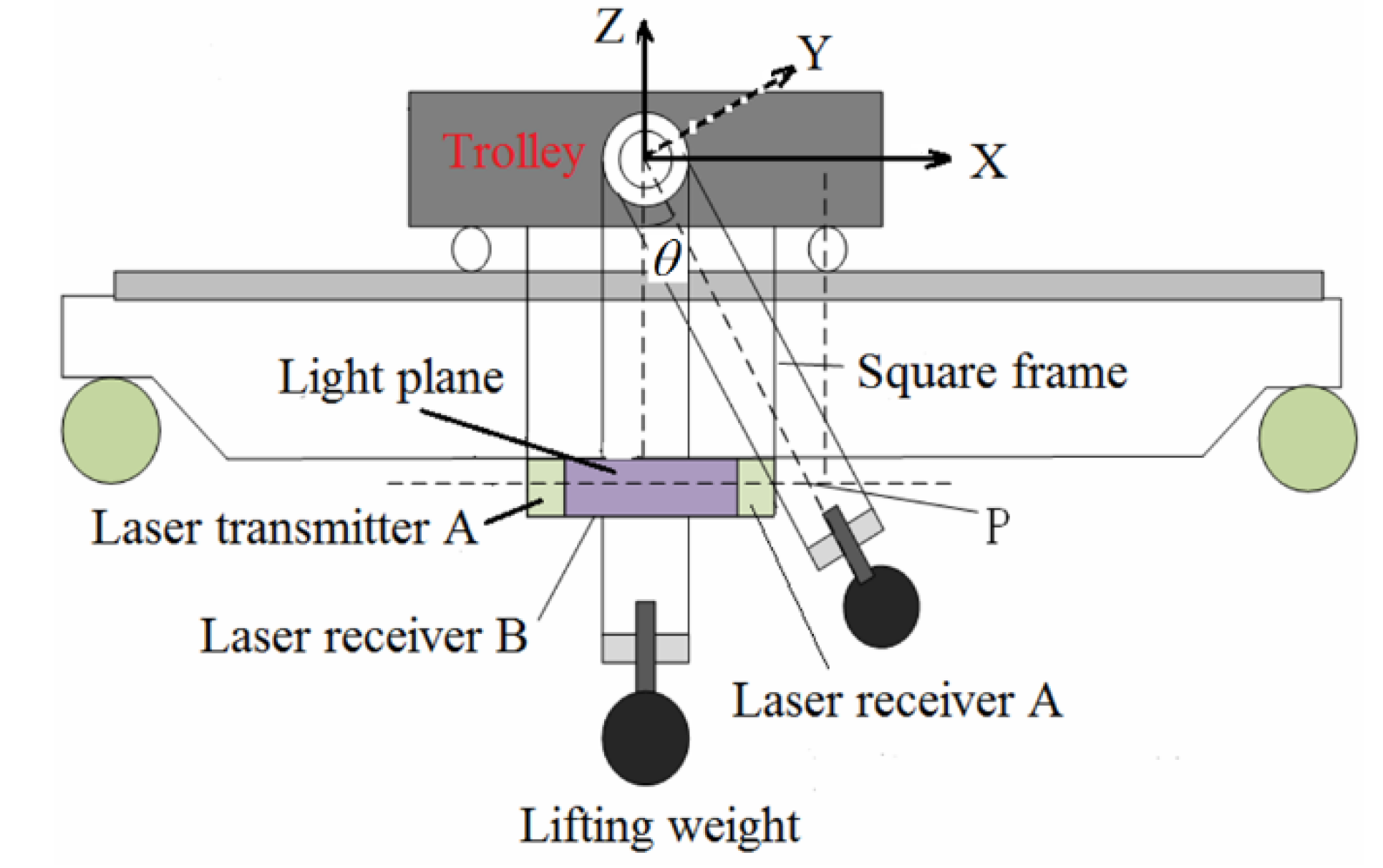
Figure 15.
Top view of crane swing angle detection device.
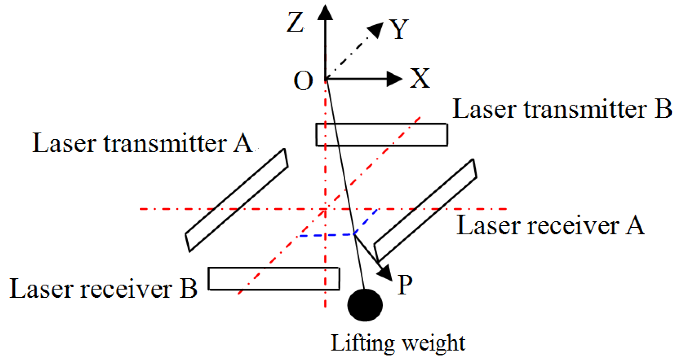
Figure 16.
Anti sway PID control structure diagram of bridge crane.
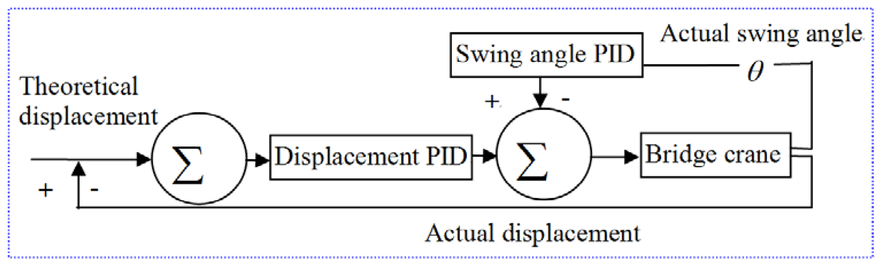
Figure 17.
System output response under critical curve method.
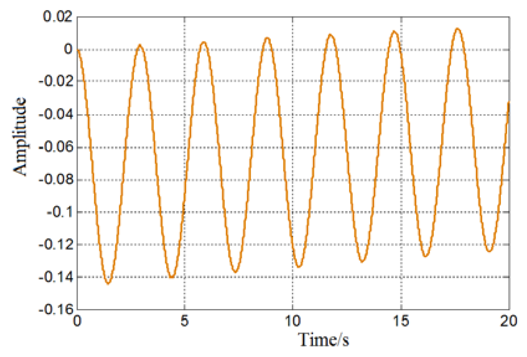
Figure 18.
Swing angle curve under the control of PID anti sway controller.
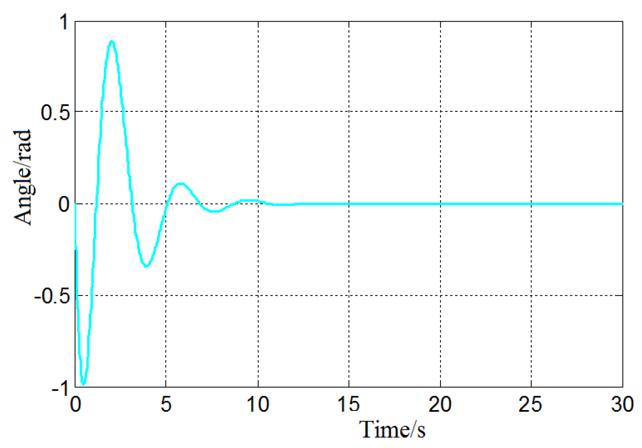
Figure 19.
Logic diagram of fuzzy control algorithm principle.
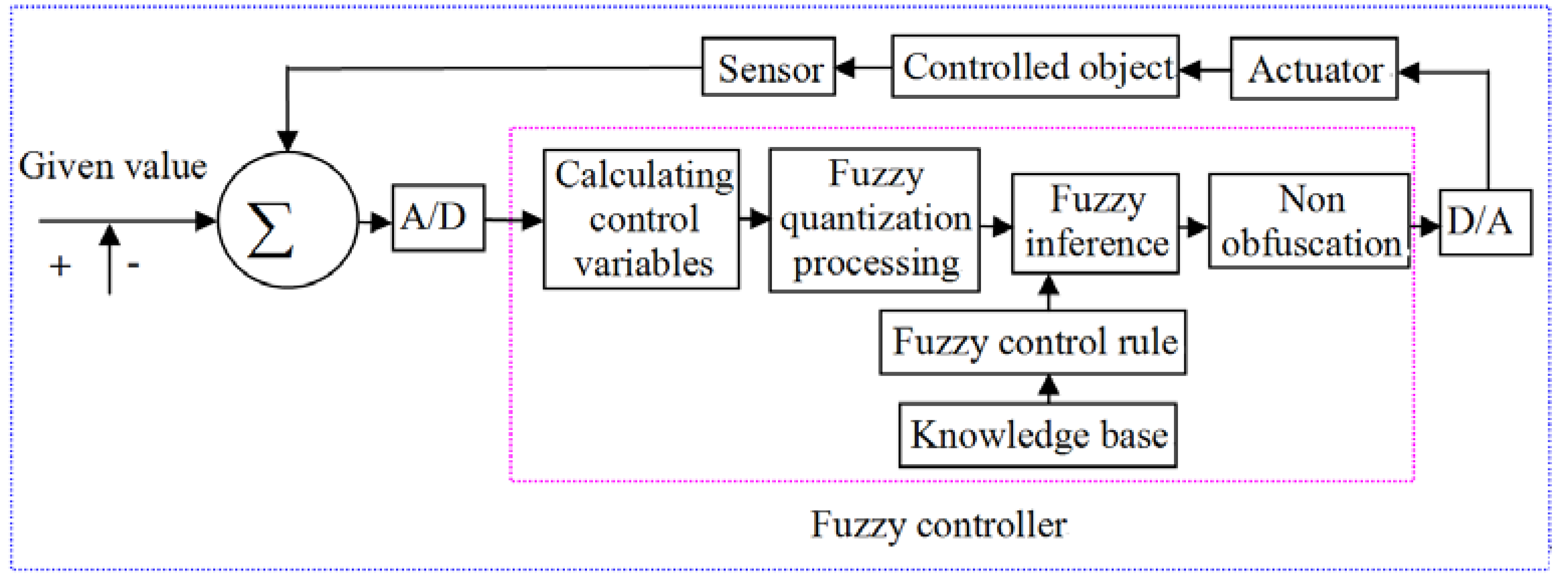
Figure 20.
Simulation Model of Anti sway Fuzzy PID Controller for Bridge Crane.
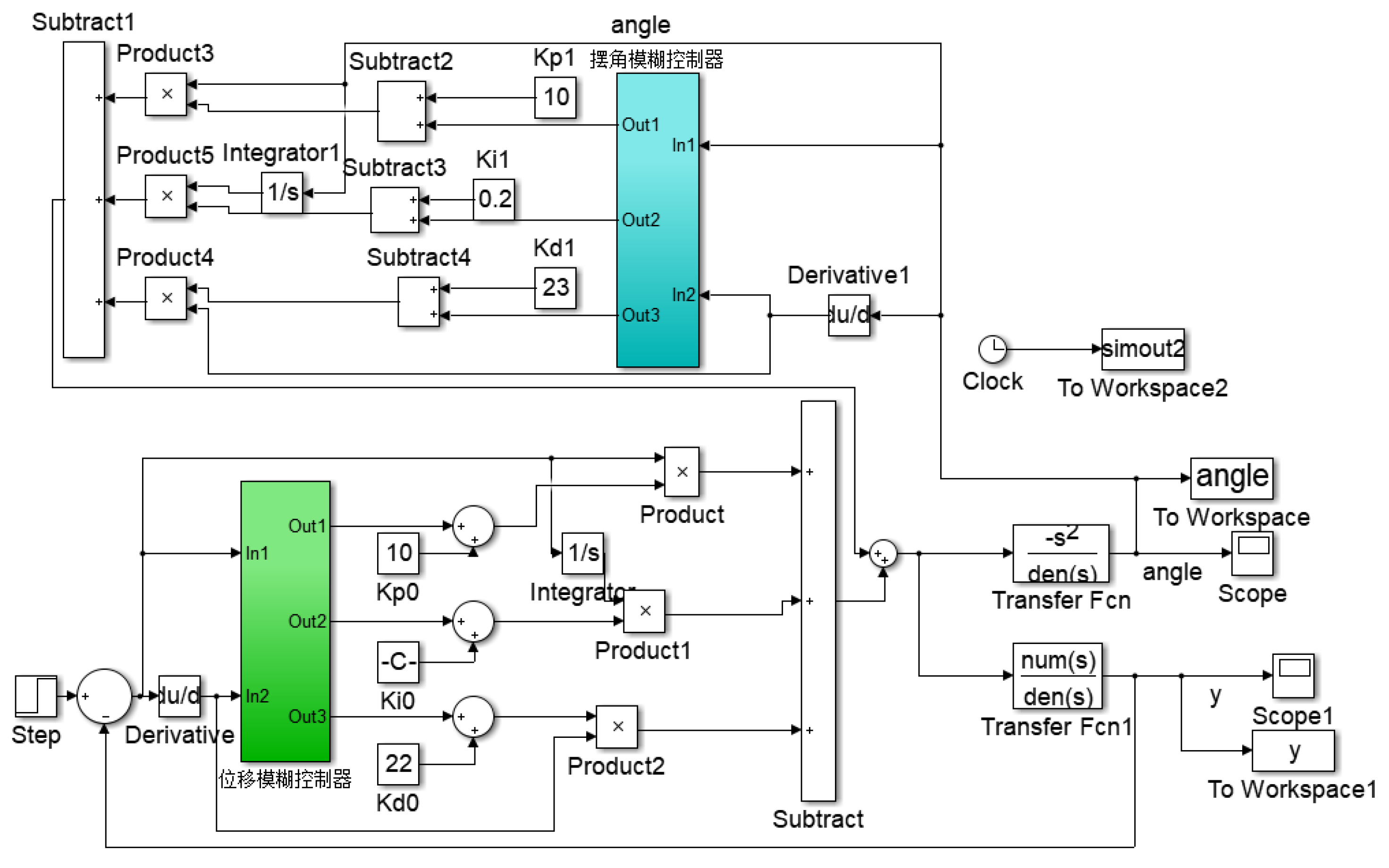
Figure 21.
The structure of Swing Angle Fuzzy Controller.
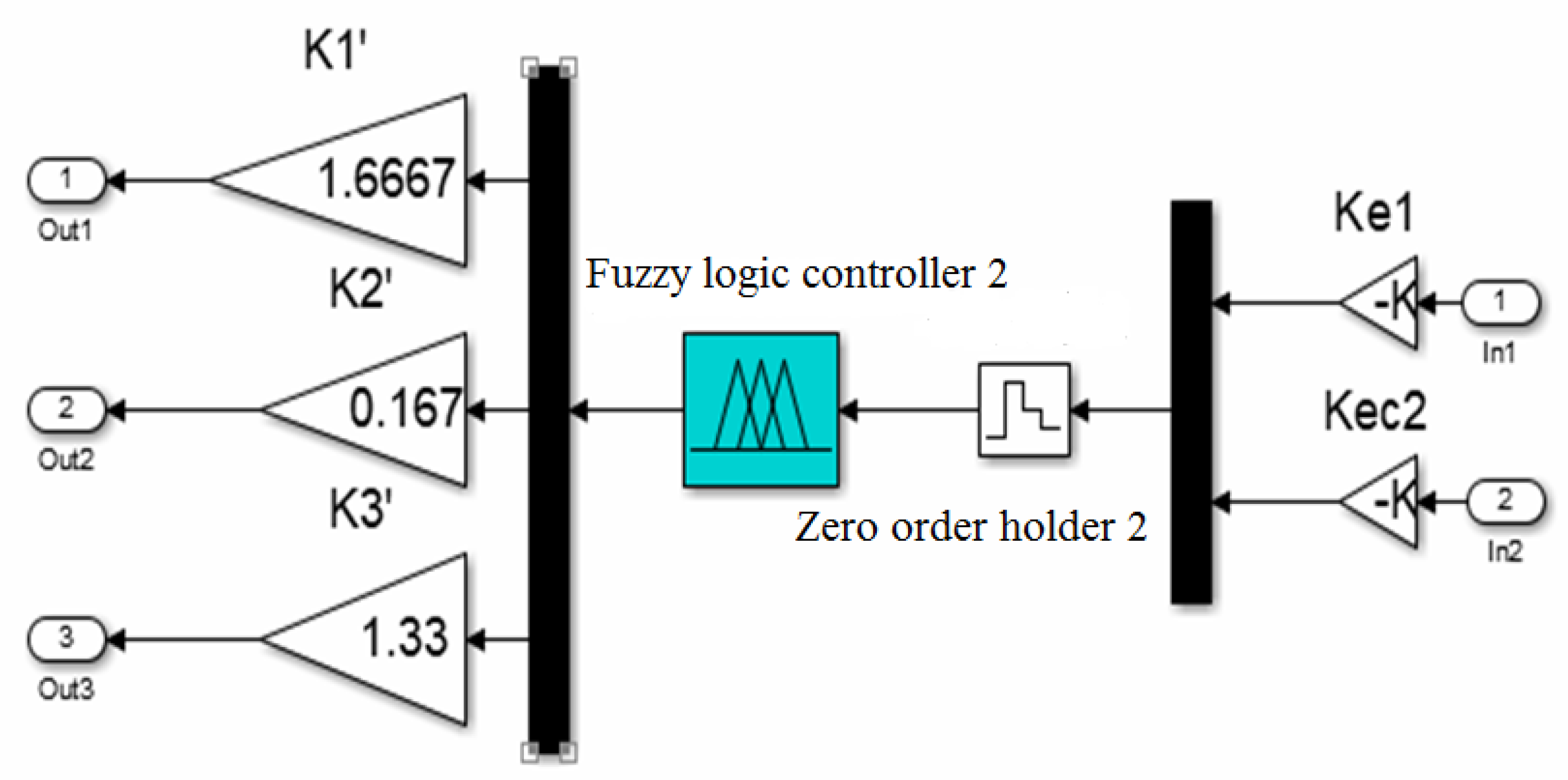
Figure 22.
Swing angle curve of crane load.
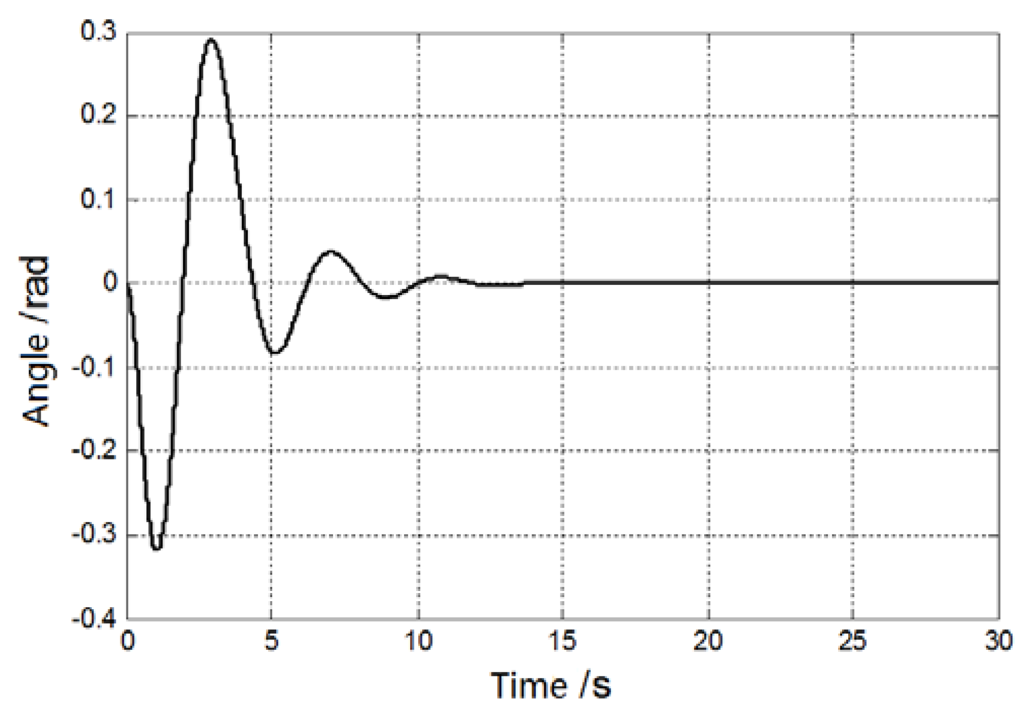
Figure 23.
Swing angle curve under different wire rope lengths.
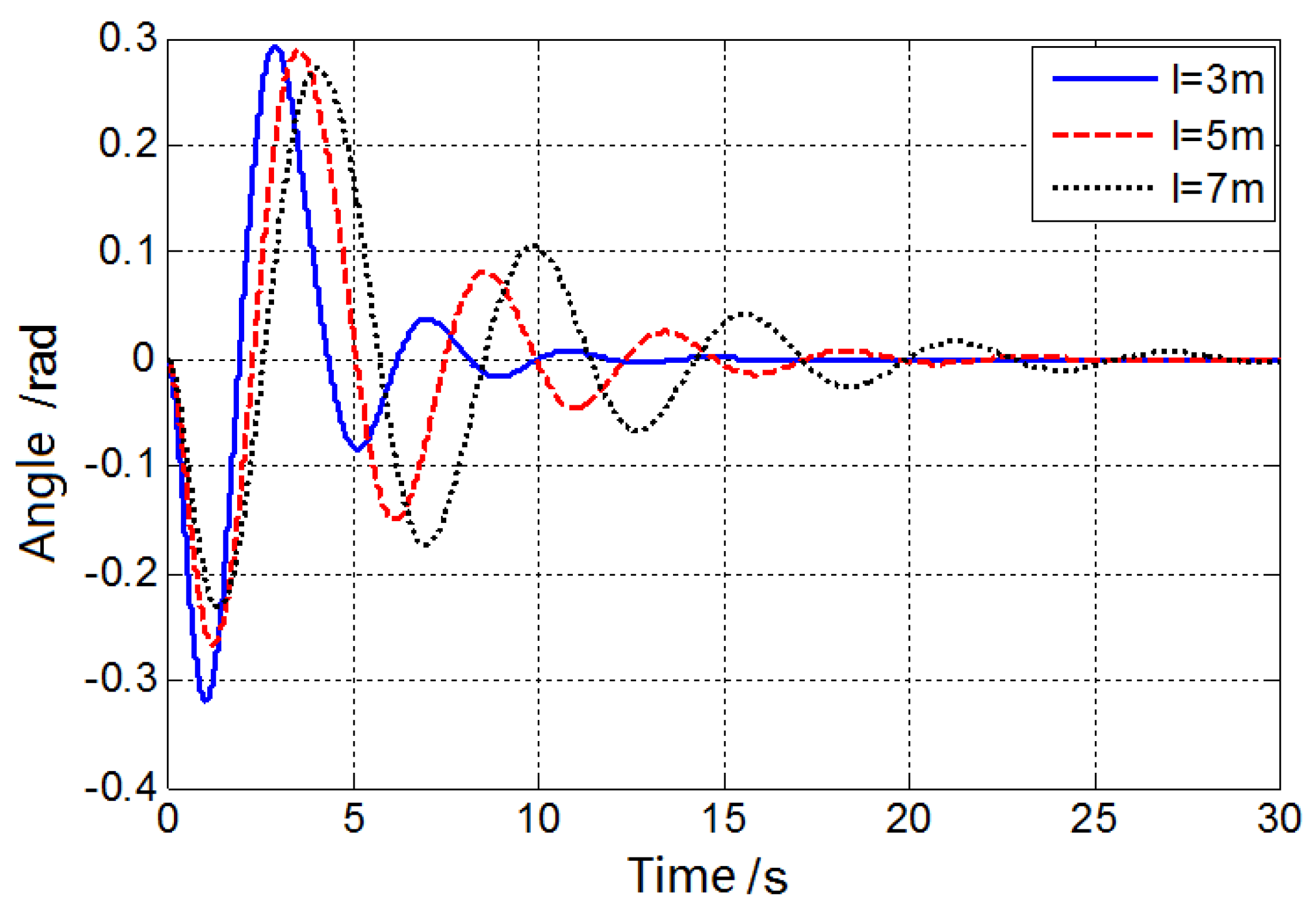
Figure 24.
Swing angle curve under different load.
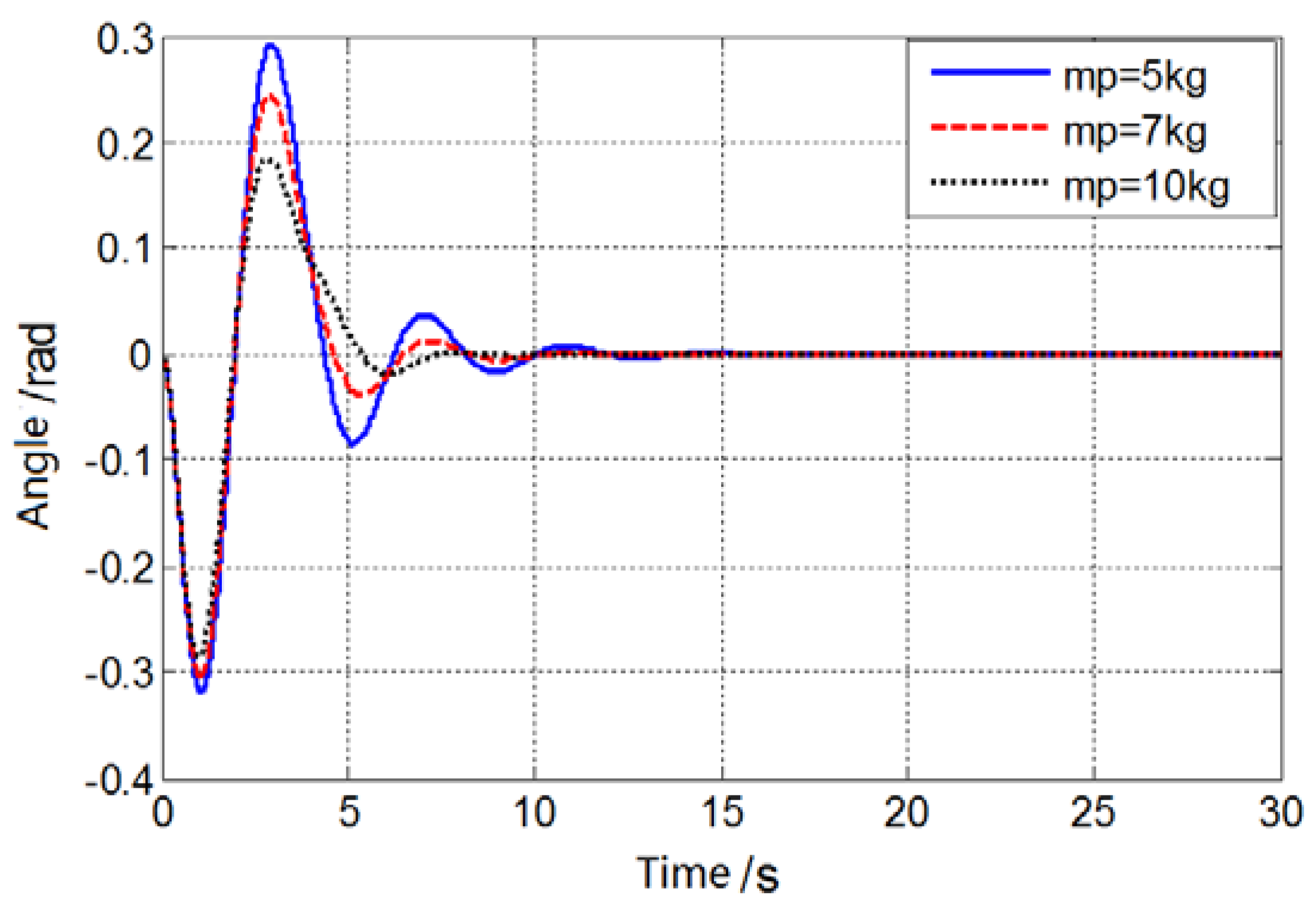
Figure 25.
Comparison of simulation results of crane swing angle.
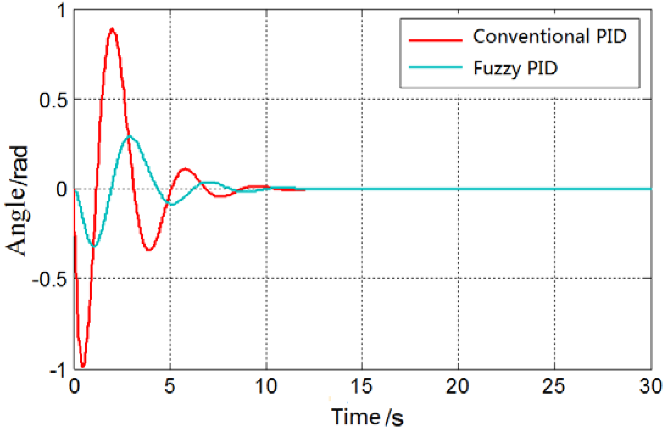

Table 1.
Parameter table of the crane.
| Additional friction resistance coefficient | |
| Deflection lateral force coefficient | |
| Single steel wire rope maximum tension | |
| Steel wire rope elastic modulus | |
| Wire rope cross sectional area | |
| Coefficient of friction of large and small trolley wheels | |
| Pulley set magnification | |
| Corresponding pulley block efficiency | |
| (The mass of small trolley) | |
| (the mass of large trolley) | |
| (the mass of lifting heavy objects) | |
| (wire rope tension) | |
| ( Full length of the wire rope below the reel without force) | 4m |
| ( additional resistance) | |
| ( Stiffness coefficient) | |
| (Wire rope elongation) |
Table 2.
Parameter Calculation Formula Based on Critical Curve Method.
| Type | |||
|---|---|---|---|
| P | 0.5 | ||
| PI | 0.445 | 0.535 | |
| PID | 0.6 | 1.2 | 0.075 |
Table 3.
Input and output variable universe and factors.
| Variable | Basic universe | Fuzzy universe | Quantification factor/scale factor |
|---|---|---|---|
| [-12 12] | [-4 4] | 0.33 | |
| [-0.5 0.5] | [-3 3] | 6 | |
| [-1.5 1.5] | [-3 3] | 2 | |
| [-1 1] | [-3 3] | 3 | |
| [-10 10] | [-6 6] | 1.667 | |
| [-0.5 0.5] | [-3 3] | 0.167 | |
| [-8 8] | [-6 6] | 1.33 |
Table 4.
Fuzzy rule table of PID parameter correction.
| PB/NB/NS | PB/NB/NS | PM/NB/NB | PM/NM/NB | PS/NM/NB | ZO/ZO/ZO | ZO/ZO/NB | ||
| PB/NB/PS | PB/NB/PS | PM/NM/PS | PM/NM/PS | PS/NS/ZO | ZO/ZO/PS | ZO/ZO/NM | ||
| PM/NM/PB | PM/NM/PB | PM/NS/PM | PS/NS/PS | ZO/ZO/ZO | NS/PS/PS | NM/PS/NM | ||
| PM/NM/PB | PS/NS/PM | PS/NS/PM | ZO/ZO/PS | NS/PS/ZO | NM/PS/PS | NM/PM/PM | ||
| PM/NS/PB | PS/NS/PM | ZO/ZO/PS | NS/PS/NS | NS/PS/ZO | NM/PM/PS | NM/PM/NS | ||
| ZO/ZO/PM | ZO/ZO/PS | NS/PS/PS | NM/PM/PS | NM/PM/ZO | NM/PB/PS | NB/PB/NS | ||
| ZO/ZO/NS | NS/ZO/ZO | NS/PS/ZO | NM/PM/ZO | NM/PB/ZO | NB/PB/PM | NB/PB/NB | ||
Disclaimer/Publisher’s Note: The statements, opinions and data contained in all publications are solely those of the individual author(s) and contributor(s) and not of MDPI and/or the editor(s). MDPI and/or the editor(s) disclaim responsibility for any injury to people or property resulting from any ideas, methods, instructions or products referred to in the content. |
© 2023 by the authors. Licensee MDPI, Basel, Switzerland. This article is an open access article distributed under the terms and conditions of the Creative Commons Attribution (CC BY) license (http://creativecommons.org/licenses/by/4.0/).
Copyright: This open access article is published under a Creative Commons CC BY 4.0 license, which permit the free download, distribution, and reuse, provided that the author and preprint are cited in any reuse.


