
Submitted:
19 April 2023
Posted:
19 April 2023
You are already at the latest version
Abstract
In order to solve the interference of narrowband communication system to ultra-wideband (UWB) system and meet the design requirements of high isolation of multiple-input multiple-output (MIMO) antenna, two MIMO antennas with double notch structures are designed. Firstly, a two-element antenna was placed symmetrically in parallel, and two rectangular branches were loaded to improve the isolation. U-shaped slots and inverted U-shaped slots are etched on the radiating patch and feeder to achieve notch characteristics in WIMAX and ITU band, respectively. Then, in order to meet more application scenarios, a four-element MIMO antenna is designed, where each element is placed orthogonally to each other, and the isolation is improved by loading a cross-shaped branches in the middle of elements. Both antenna samples are tested to verify the design. Measured results show that the working bandwidth of the two-element UWB MIMO antenna is 2.45-14.88 GHz, the isolation is greater than 17 dB, the peak gain is 5.7 dB, the maximum radiation efficiency can reach 96%, the envelope correlation coefficient (ECC)is less than 0.02. Meanwhile, the working bandwidth of the four-element antenna is 2.14-14.95 GHz, the isolation is greater than 20 dB, the peak gain is 5.9 dB, the maximum radiation efficiency can reach 95%, the ECC is lower than 0.05. They both are with very good omnidirectional characteristic, and meet the requirements of the UWB application.
Keywords:
coplanar waveguide
; double band-notched
; mutual coupling
; MIMO antenna
; UWB antenna
; isolation
; orthogonal elements
1. Introduction
With the rapid development of wireless communication technology, ultra-wideband (UWB) technology has become the focus of many researchers due to its advantages of high transmission rate, low power consumption, omnidirectional radiation characteristics and wide bandwidth. So far, UWB technology has been widely applied in the fields of ground-penetrating radar [1-2], wireless sensor [3], precise positioning [4], biomedical engineering [5-6] and so on. However, many narrowband communication bands will strongly interfere with the normal operation of the UWB system, because these bands are also included in the operating bandwidth of the UWB system. For example, WiMAX (3.3-3.7 GHz), International satellite band (4.5-4.8 GHz), International Telecommunication Union band (ITU, 8.01-8.5 GHz) and so on [7]. At present, the simplest way to suppress the interference problem of narrowband signal is to design the UWB antenna with band-notched characteristic. In the design of UWB antenna, the main methods to achieve the notch characteristic of antenna are etching slots [8], adding defected ground structures [9] and adding parasitic elements [10,11]. The advantages of these methods are simple structure, easy design, little influence on impedance matching in the working frequency band, ensure that the antenna can work normally in the working frequency band, and the size of the original antenna will not increase, which is conducive to the miniaturization and large-scale integration of the antenna. It is also found that the UWB system is difficult to achieve long-distance transmission under the condition of limited power, and the UWB channel has extremely rich frequency components, belonging to the high-frequency selective fading channel. If the symbol length is smaller than the path delay, very serious inter-symbol interference will be generated, thus reducing the signal transmission efficiency and transmission quality of the UWB system. Therefore, multiple-input multiple-output (MIMO) technology is introduced to solve the above problems. MIMO technology increases the channel capacity and improves the transmission quality of the channel by placing multiple antenna elements at the transmitter and receiver [12]. The combination of UWB technology and MIMO technology can increase the signal transmission distance of UWB antenna without changing the power and reduce the disadvantage caused by multipath fading. However, in many practical scenarios, the design requirements for UWB MIMO antennas are high, and the antennas need to be as small as possible in order to better integrate into the actual system. However, too small antenna volume will increase the coupling between antenna elements, so it is necessary to improve the isolation degree between antenna elements. At present, the methods to improve the isolation degree include introducing conductor branches [13], etching slots between antenna elements [14], loading neutralization line [15,16], and improving the isolation performance of antenna through reasonable layout of antenna elements [17-22].
To solve the above problems, the UWB MIMO antenna with double-notched characteristics is investigated. First, two-element parallel antenna is designed with the size of 38 mm×68 mm×1.6 mm, which can be better integrated into various wireless communication devices and has the characteristics of suppressing WIMAX and ITU band interference on UWB system. In addition, the antenna isolation can reach 17 dB, which meets the requirement that the isolation degree of MIMO antenna is higher than 15 dB in practical engineering. In order to adapt to more application scenarios, a four-element UWB MIMO antenna with double-notched characteristics is designed. The antenna size is only 68 mm×68 mm× 1.6mm, which also has the characteristics of suppressing the interference of WIMAX and ITU bands to the UWB system, and the antenna isolation can reach 20 dB. The simulation and measurement results show that the two MIMO antennas have good performance and can be widely used in various wireless communication devices.
In this paper, a compact two-element MIMO antenna and a more compact four-element orthogonal MIMO antenna are proposed with dual notched characteristics at WIMAX and ITU bands. The total antenna structure design with its geometric specifications is introduced Section II. The notch and decoupling design of two antennas are simulated and the corresponding parameters and principles are analyzed in Section III, where the scattering matrix, radiation pattern, and the current distribution is simulated. Fabricated sample is measured in Section IV, and results from simulation and experiment have been discussed. Finally, conclusions are drawn in Section V.
2. Antenna Structure and Design
Two MIMO antennas are designed, one is a two-element UWB MIMO antenna with double notch characteristics, and its structure diagram is shown in Figure 1(a). The other is a four-element UWB MIMO antenna with double notch characteristics, and its structure diagram is shown in Figure 1(b). Both MIMO antennas are fed by coplanar waveguide (CPW) and printed on F4BTM440 dielectric substrates with a relative dielectric constant of 4.4 and a tangent loss of 0.0015. The two MIMO antennas have the same antenna element, which adopts microstrip monopole antenna structure, including a semicircular radiation patch, two inverted trapezoidal radiation patch, feeder and ground plane. The width of the feeder is Wm to meet the impedance matching of 50 Ω. In this paper, U-shaped slots are etched on the radiation patch of the antenna element to realize the notch of WIMAX band, and inverted U-shaped slots are etched on the feeder of the antenna element to obtain the notch of ITU band. To obtain the notch property, the most important thing to calculate is the total length of the etched slot. The total length of the slot can be estimated by formula (1) and (2):
Where, fn is the center frequency of notch; c is the speed of light; L is the length of the slot; ɛe is the equivalent permittivity; ɛr is the dielectric constant of the dielectric substrate. According to formula (1) and (2), when the center frequency is 3.5 GHz, the length of the U-shaped slot is about 26 mm. The electromagnetic simulation software HFSS is used for optimization, and the stopband characteristics are the best when the length of the U-shaped slot is 25.8 mm, which can completely cover the WIMAX band. At a center frequency of 8.3 GHz, the length of the inverted U-shaped slot is approximately 11 mm. After optimization by electromagnetic simulation software HFSS, when the length of inverted U-shaped slot is 11.8mm, the stopband characteristics are the best, which can cover the ITU band completely.
The antenna elements of the two-element MIMO antenna are placed symmetrically, and two rectangular branches are loaded between the antenna elements. The two rectangular branches can generate two new current paths, reduce the coupling current between the ports, and improve the isolation between the antenna elements. The four antenna elements of the four-element MIMO antenna are placed orthogonal to each other, and the antenna elements have different polarization modes, resulting in mismatch of polarization between adjacent antenna elements, thus improving the isolation degree between antenna elements. In order to further improve the isolation degree of the four-element MIMO antenna, a cross branch is added in the center of the dielectric substrate. After simulation and optimization of electromagnetic simulation software HFSS, the geometric dimensions of the two MIMO antennas are shown in Table 1.Interventionary studies involving animals or humans, and other studies that require ethical approval, must list the authority that provided approval and the corresponding ethical approval code
3. Simulation Result Analysis
3.1. Notch design and parameter analysis
In order to avoid the interference problem of narrowband communication system, U-shaped slots in the radiation patch of UWB antenna and inverted U-shaped slots in the feeder are used to generate notch properties. In order to verify the mutual independence of the two notch structures, Figure 2 shows the |S|-parameter simulation curve corresponding to the UWB MIMO antenna when no notch structures are introduced and when different number of notch structures are introduced respectively.
The non-notch curve in the figure represents the |S11| of the UWB MIMO antenna without notch structure. It can be seen that the operating frequency band of the antenna is 2.12-14.73 GHz, but in the 4.2-4.6 GHz band, the impedance matching of the antenna is poor, but it still meets the design requirements. The single notch curve represents the |S11| after the U-shaped slot is loaded on the radiation patch of the UWB antenna. The working frequency band of the antenna changes to 2.05-14.54 GHz, and a stopband appears in the frequency band of 3.28-3.75 GHz, which just includes the narrow band of WIMAX. The notch property of the antenna in this frequency band is realized. The double notch curve corresponds to |S11| after the inverted U-shaped slot is loaded on the antenna feeder on this basis. The working bandwidth of the antenna changes to 2.02-14.74 GHz, and the notch is generated in the frequency band of 7.99-8.58 GHz, and the inverted U-shaped slot has almost no effect on the first notch frequency band, which proves that the two notch structures are independent of each other. The antenna notch property in ITU frequency band is realized. Finally, the above two narrow band frequency bands were accurately filtered.
In order to study the influence of U-shaped slot and inverted U-shaped slot on the notch characteristics, the key dimensions of the two kinds of notch structures were parameterized and simulated by HFSS. In the simulation, port 1 was the excitation port, and port 2 was connected with 50 Ω load. As shown in Figure 3, when L3 increases from 6.8 mm to 7.2 mm and other parameters remain unchanged, the center frequency of the notch band 3.28-3.75 GHz changes significantly, decreasing from 3.6 GHz to 3.5 GHz. When L3=7.0 mm, the stopband bandwidth of the antenna just covers the WIMAX band. Figure 4 shows the influence of the location of the U-shaped slot on antenna |S11|. When H1 increases from 20.4 mm to 20.8 mm, the center frequency of the 3.28-3.75 GHz notch band does not change significantly, but the stopband bandwidth of the 3.28-3.75 GHz notch band gradually increases. It can be seen from the above analysis that the notch frequency band can be flexibly controlled by adjusting the length and position of U-shaped slot of notch structure.
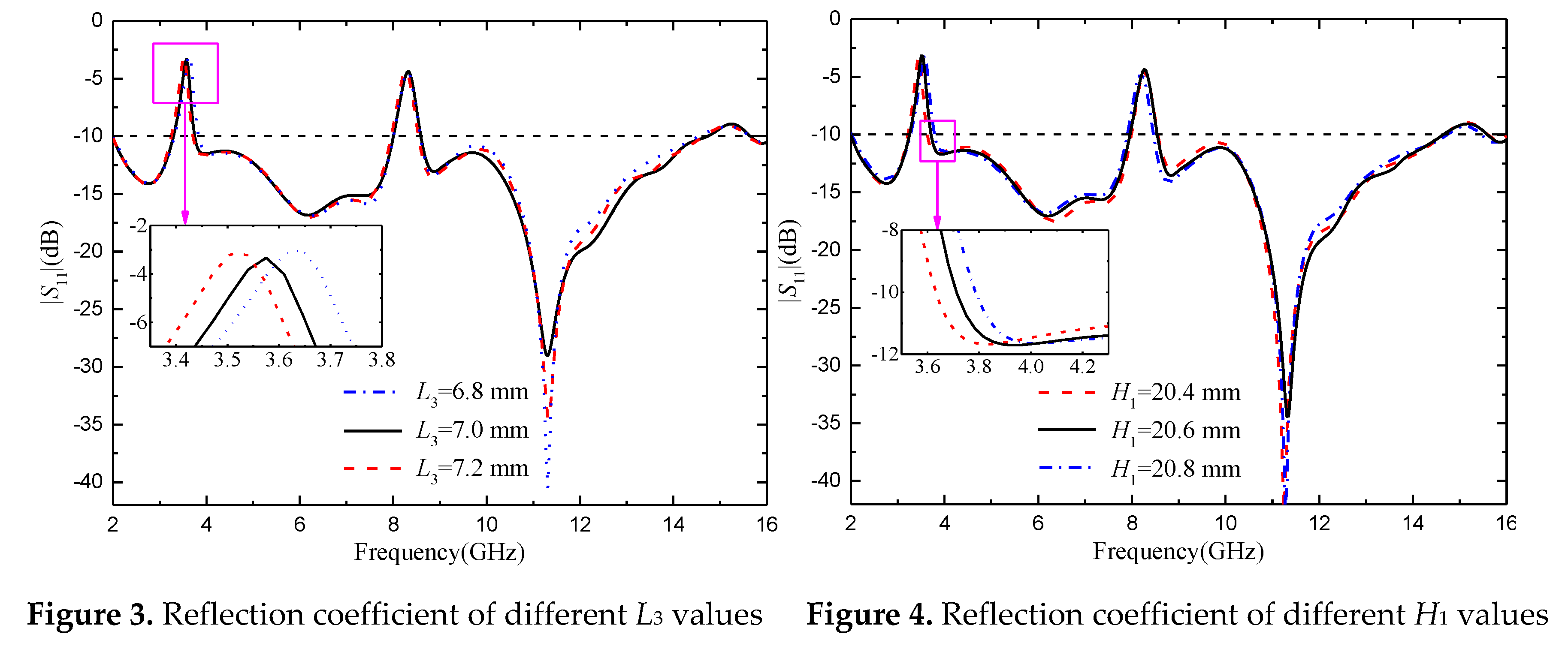
Figure 5 shows the corresponding |S11| simulation curve when the key parameters of the inverted U-shaped slot with notch structure change. As shown in Figure 5, when other parameters of the inverted U- shaped slot remain unchanged and L4 increases from 4.7 mm to 5.1 mm, the notch band 3.28~ 3.85 GHz does not change significantly, and the center frequency of the notch band 7.99-8.58 GHz will gradually decrease. Since the inverted U-shaped slot is etched on the feed line of the antenna, the position of the inverted U-shaped slot has obvious influence on the two notch bands of the antenna. After simulation, it is known that when H2=11 mm, the ITU frequency band can be covered exactly. By optimizing the key parameters of the two notch structures, it can be seen that the U-shaped slot mainly affects the notch band at 3.28~ 3.85 GHz, and the inverted U-shaped slot mainly affects the notch band at 7.99-8.58 GHz, with little mutual interference.
In order to understand the principle of antenna notch, it is further analyzed to determine the relationship between U-shaped slot and inverted U-shaped slot and corresponding notch segment. Taking unit antenna as an example, the surface current of unit antenna is simulated. Figure 6 shows the antenna surface current distribution at two notch center frequencies of 3.55 GHz and 8.25 GHz and two passband frequency points of 5.5 GHz and 12.5 GHz. It can be seen from the figure that the current at 3.55 GHz is mainly concentrated in the U-shaped slot, and the current at 8.25 GHz is mainly concentrated in the inverted U-shaped slot. Since energy is concentrated in these two places, it cannot radiate outward, so it produces a trap wave. At the passband frequencies of 5.5 GHz and 12.5 GHz, the electric field on the patch and ground floor is evenly distributed, and the electric field near the feeder and the power port is the largest, and the energy can be radiated out, which confirms that the antenna can work normally on the passband frequency.
3.2. Decoupling design and parameter analysis
3.2.1. Two-element MIMO antenna
In order to study the influence of rectangular branches on UWB MIMO antennas and the decoupling effect, HFSS is used to simulate and analyze the UWB MIMO antennas with unloaded rectangular branches and loaded rectangular branches, and the parameters of rectangular branches are scanned and analyzed.
Figure 7 shows the comparison of S-parameters before and after antenna loading rectangular branches, (a) represents |S11|, (b) represents |S21|. As can be seen from Figure 7(a), loading rectangular branches will deteriorate the antenna's impedance matching in the 4-10 GHz frequency band, but the influence is small. The antenna can still meet the design requirements and meet the performance indexes of UWB antennas. As can be seen from Figure 7(b), when the rectangular branches are not loaded, the antenna's isolation degree is higher than -15 dB in the 8.7-8.9 GHz and 12.64-13.41 GHz bands, and the isolation effect is poor, which does not meet the basic requirements for designing MIMO antennas. However, after loading the rectangular branches, the antenna isolation is obviously improved, especially in the 5-13 GHz frequency band, the antenna isolation is lower than -20 dB, and the antenna isolation is also lower than -16 dB in the other frequency bands of the working frequency band, with an average decrease of about 7 dB, indicating an obvious isolation effect. In short, figures (a) and (b) show that rectangular branches effectively inhibit electromagnetic coupling between antenna elements, and significantly improve the isolation degree between elements. At the same time, the |S11| of the antenna changed little and remained below -10 dB in the UWB band, and the antenna did not appear impedance mismatch phenomenon.
In order to further study the influence of the isolation structure on the antenna performance, the key dimensions of the isolation structure were parameterized, and the simulation was optimized by using HFSS software. Port 1 of the MIMO antenna was set as the excitation port, and port 2 was connected to 50 Ω load.
Figure 8 represents antenna S-parameters corresponding to different L6 values, where (a) represents |S11| and (b) represents |S21|. As can be seen from Figure (a), the change of L6 has little overall influence on the impedance matching of the two-element MIMO antenna. |S11| only has some changes in the WIMAX band, which will affect the initial frequency of the notch band. When L6=20 mm, the notch band just covers the WIMAX band, accurately meeting the notch requirements. As can be seen from Figure (b), the change of L6 has a significant impact on the isolation degree of the two-element MIMO antenna. With the increase of L6, the isolation degree between the two antenna elements increases, and the decoupling effect is better. In general, when L6=20 mm, the antenna can accurately cover the notch band, but also has a high isolation degree, the isolation degree is lower than -15 dB, meet the basic design requirements of MIMO antenna, has a good decoupling effect.
Through simulation and optimization, it is found that other dimensions of isolation branches have little influence on antenna impedance matching, and have no significant effect on the improvement of isolation degree, so it will not be analyzed and described.
In order to more directly reflect the function of rectangular isolated branches, Figure 9 shows the surface current comparison diagram of without and with rectangular isolated branches at frequencies of 3 GHz, 7.25 GHz and 11.6 GHz. Where, (a) represents the surface current comparison of the antenna at 3 GHz, (b) represents the surface current comparison of the antenna at 7.25 GHz, and (c) represents the surface current comparison of the antenna at 11.6 GHz. Port 1 of the two-element MIMO antenna acts as the excitation port, and port 2 is connected to the 50 Ω load. It can be clearly seen from the comparison figure that when the rectangular isolation branch structure is not added, there are more green areas on the feeder and radiation patch of the antenna element where port 2 is located, which indicates that the surface current intensity of the antenna element where port 2 is located is relatively large, and further proves that part of the energy of port 1 is coupled to port 2. When the rectangular decoupling structure was added between the two antenna elements, it could be seen that the surface current intensity of the radiation patch of the antenna element where port 2 was located decreased significantly, which indicated that most of the energy was separated by the rectangular branches, and also proved that the antenna element where port 1 was located had little energy coupled to port 2. The comparison shows that the decoupling structure can well isolate the interference between antenna elements, improve the isolation degree between two ports, and realize the function of port isolation.
3.2.2. Four-element MIMO antenna
After increasing the number of MIMO antenna elements, it will increase the difficulty of decoupling. Therefore, each element of the four-element MIMO antenna is placed orthogonal first. The orthogonal placement of antenna elements will lead to the polarization mismatch of adjacent antennas, thus reducing the coupling between antenna elements and improving the degree of isolation between antenna elements. Due to the MIMO antenna has a symmetrical structure, so the antenna the antenna element |S11| equal, at the same time, the degree of isolation between antenna element meet |Sij| = |Sji| (i≠j; i, j≤4). In order to more convenient to study the MIMO antenna S-parameter changes, this can only study antenna element 1 S-parameters. Figure 10 is the S-parameter diagram of the four-element MIMO antenna. It can be seen from the figure that the operating frequency band of the antenna is 2.17-14.71 GHz, in which the notch band of the U-shaped slot is 3.26-3.89 GHz, and the notch band of the inverted U-shaped slot is 7.93-8.51 GHz. Two notch bands can cover WIMAX band and ITU band respectively. When port 1 is excited, the isolation degree between port 1 and port 2 and between port 1 and port 4 is lower than -23 dB, and the isolation degree between port 1 and port 3 is lower than -15 dB in the working frequency band. It can be proved that the orthogonal placement of antenna elements can reduce the coupling between antenna elements and obtain good polarization diversity effect. Since the isolation between port 1 and port 3 just meets the basic design requirements, considering that the addition of antenna elements will increase the instability of antenna operation, it is necessary to further improve the isolation between port 1 and port 3.
In order to further improve the isolation degree between the antenna elements of the four-element MIMO antenna, the center of the dielectric substrate is loaded with cross-shaped branches for decoupling. In order to study the influence of cross-shaped branches on antenna performance, the key parameters of the cross-shaped branches are scanned and optimized by HFSS. Port 1 of the MIMO antenna is set as the excitation port during simulation. Other ports are connected to 50 Ω loads. Figure 11 is the S-parameter diagram of the four-element MIMO antenna after loading the cruciform branches. As can be seen from Figure 11, the addition of cross-shaped branches significantly reduces the isolation degree between port 1 and port 3, but has little impact on the isolation degree between port 1 and other ports. The isolation degree between ports is lower than -21 dB, which has a good decoupling effect. The working frequency band of the four-element MIMO antenna is 2.13-14.62 GHz, in which the frequency band of the U-shaped slot becomes 3.27-3.87 GHz, and the frequency band of the inverted U-shaped slot becomes 7.89-8.65 GHz. The two frequency bands can still cover the WIMAX and ITU band respectively. The antenna has accurate trapping property and good impedance matching.
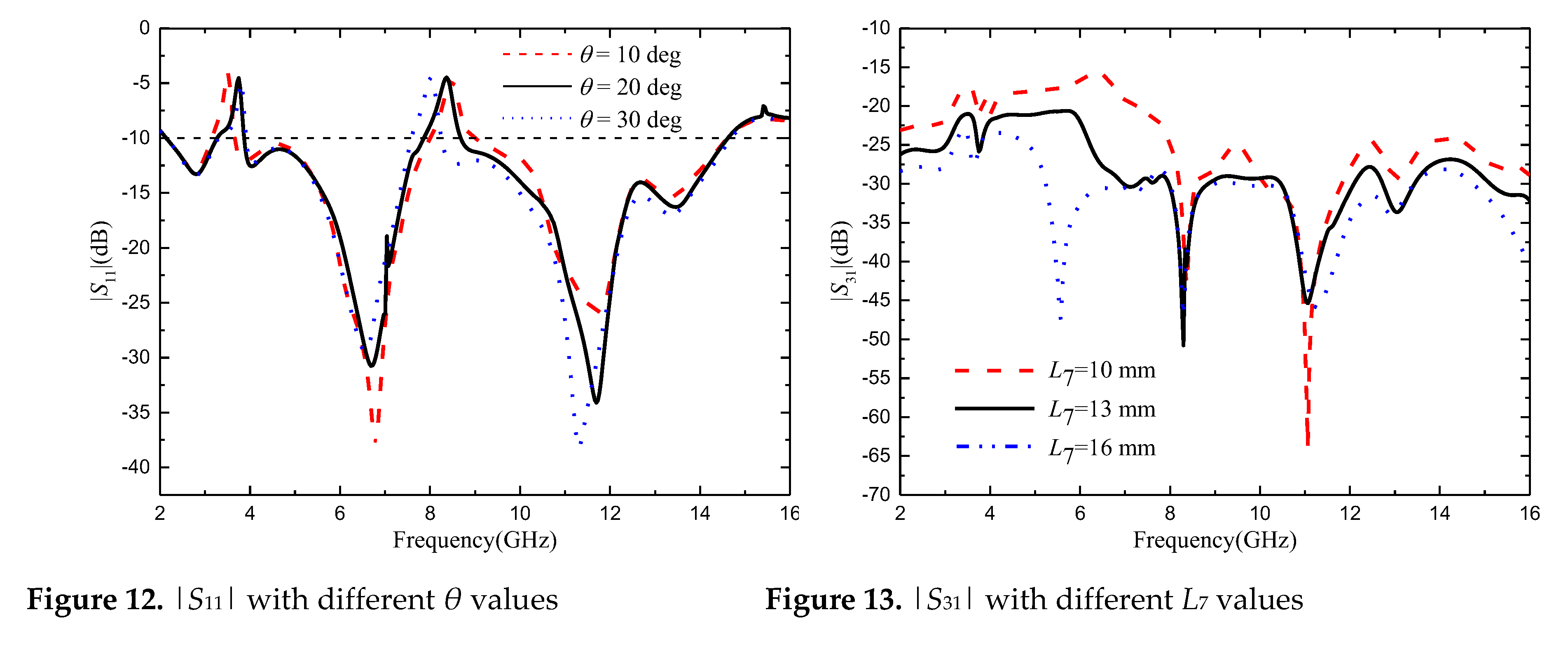
Through simulation analysis, it is found that the rotation Angle θ of the cross branch has a great influence on the notch band of the four-element MIMO antenna, and the length of the cross branch has a significant effect on improving the isolation between port 1 and port 3. The antenna parameter θ was set as 10-30 deg, and the step size was set as 2 deg. Figure 12 shows |S11| with different θ values. It can be seen from the figure that when θ increases from 10 deg to 30 deg, the center frequency of the notch band corresponding to U-shaped slot gradually increases, while that corresponding to the notch band corresponding to the inverted U-shaped slot gradually decreases. When θ=20 deg, the two notch bands exactly cover the WIMAX and ITU band. The antenna parameter L7 is set from 10 mm to 16 mm, and the step is set to 1 mm. |S31| corresponding to different values of L7 is shown in Figure 13. As can be seen from the figure, as L7 increases, the isolation between port 1 and port 3 gradually increases. However, with the change of the value of L7, the accuracy of the notch band will be slightly affected. When L7=13 mm, the antenna has a high degree of isolation and the notch band can achieve accurate coverage.
In order to more directly reflect the effect of orthogonal placement of antenna elements and the isolation effect after loading the cross branches, Figure 14 shows the surface current comparison diagram of the four-element MIMO antenna at the frequencies of 4.5 GHz, 7.25 GHz and 11.6 GHz. When port 1 is energized, the other ports are loaded with 50 Ω load. As can be seen from FIG. 14, when the cross branches are not loaded, part of the energy of port 1 is coupled to other ports. From the current distribution on the antenna surface, the coupled energy is small, which proves that the isolation degree can be improved by placing antenna elements orthogonal to each other. By observing the current distribution of the antenna surface with the cross-shaped branches loaded, it is found that the energy coupled from port 1 to other ports is less than that without the cross-shaped branches loaded. The currents on both sides of the cross-shaped branches form opposite directions, and the electric fields radiated by the cross-shaped branches cancel each other in opposite directions to realize the decoupling effect, which further proves that the cross-shaped branches can improve the isolation between antenna elements.
4. Measured Results and Analysis
In order to verify the performance of the two MIMO antennas designed, the antennas are manufactured according to the data in Table 1. Vector network analyzer (N5244A) and microwave anechoic chamber were used to measure the MIMO antenna |S|-parameter and far-field radiation pattern, as shown in Figure 15 and Figure 16.
4.1. S-parameter
4.1.1. Two-element MIMO antenna
Figure 17 shows the two-element UWB MIMO antenna simulation and the measured |S|-parameters, due to the symmetry of the antenna unit, only consider the |S|-parameters of port 1. As can be seen from the figure, the measured working frequency band of the antenna is 2.45-14.88 GHz, which can cover the UWB frequency band. The notch band corresponding to the U-shaped slot is 3.26-3.75 GHz, and the notch band corresponding to the inverted U-shaped slot is 7.96-8.65 GHz, which can cover the WIMAX and ITU band respectively. The measured isolation between two antenna ports is lower than -18 dB. By comparing the simulation results and the measured results in Figure 17, it can be seen that the measured |S|-parameters are roughly consistent with the simulated |S|-parameters. However, due to the errors caused by antenna machining, welding process and network analysis instruments, the measured and simulated values have a small difference.
4.1.2. Four-element MIMO antenna
Figure 18 shows the simulation and the measured S-parameters of the four-element UWB MIMO antenna, due to the symmetry of the antenna element, only consider the S-parameters of port 1. As can be seen from the figure, the measured working frequency band of the antenna is 2.14-14.95 GHz, which can cover the UWB frequency band. The notch band corresponding to the U-shaped slot is 3.02-3.99 GHz, and the notch band corresponding to the inverted U-shaped slot is 7.56-8.58 GHz. The bandwidth of the two notch bands becomes wider. However, WIMAX and ITU band can still be covered separately. The measured isolation degree between each antenna port is lower than -20 dB, which proves that the isolation degree between antenna elements is high and they can maintain independent normal operation. By comparing the simulation results and the measured results in Figure 18, it can be seen that the measured |S|-parameters are roughly consistent with the simulated |S|-parameters, which proves that the antenna has good performance.
4.2. Radiation pattern
4.2.1. Two-element MIMO antenna
Figure 19 shows the measured radiation pattern of the two-element MIMO antenna at the operating frequencies of 4.2, 6.8 and 10.6 GHz when port 1 is excited and port 2 is connected to a 50 Ω load. It can be seen from the figure that the radiation pattern of E-plane is good at 4.2 GHz and 6.8 GHz, but becomes irregular at 10.6 GHz, while the H-plane shows omnidirectional characteristics at 4.2 GHz and 6.8 GHz, and becomes irregular at 10.6 GHz. With the increase of frequency, the wavelength of the antenna decreases and is no longer much larger than the size of the antenna. The antenna no longer has the characteristics of an electrically small antenna. Therefore, the radiation pattern of the antenna changes and no longer presents the radiation pattern similar to that of a monopole antenna. Although the shape degradation and deformation of antenna radiation pattern will occur at high frequency, the radiation intensity still meets the communication requirements of UWB antenna. It can be seen from the radiation pattern of the antenna that the antenna is an omnidirectional antenna, which is suitable for most scenarios of UWB technology application.
4.2.2. Four-element MIMO antenna
Figure 20 shows the measured radiation pattern of the four-element MIMO antenna at the operating frequencies of 4.0, 7.6 and 11.6 GHz when port 1 is excited and other ports are connected to a 50 Ω load. It can be seen from the figure that the radiation pattern of E-plane is good at 4.0 GHz and 7.6 GHz, but becomes irregular at 11.6 GHz, while the H-plane shows omnidirectional characteristics at 4.0 GHz and 7.6 GHz, and becomes irregular at 11.6 GHz. Although the antenna radiation pattern is deformed at high frequency, it still meets the design requirements of UWB antenna. The antenna is omnidirectional and suitable for most UWB technology application scenarios.
4.3. Envelope Correlation Coefficient
The envelope correlation coefficient is used to measure the correlation between the channels of MIMO antenna units. It refers to the correlation between different signal amplitudes received by the antenna. For MIMO antennas, smaller ECC means weaker channel correlation and better system performance. In general engineering applications, if the ECC is less than 0.5 [24], it can be considered that the antenna channels can work independently. The calculation of S parameter for ECC [23]is shown in Formula (3):
Where Sii, Sij, Sji and Sjj are the real parts of the S-parameter, and S*ii and S*ji are the imaginary parts of the S-parameter.
Figure 21(a) shows the ECC of the two proposed MIMO antennas, which shows that the ECC is very small (< 0.02) in the whole passband bandwidth except for the notch band. Although the ECC is affected by these notch structures, it is less than 0.03 in the whole impedance bandwidth. Similarly, it can be seen from Figure 21(b) that except for the notch band, the ECC within the passband bandwidth is less than 0.02, and the entire impedance bandwidth is less than 0.05. The ECC values of the two proposed MIMO antennas are low and meet the standard of ECC less than 0.5, which indicates that the antennas have good diversity performance and can be effectively applied in multi-antenna systems.
4.4. Diversity Gain
Diversity gain (DG) is another important parameter to measure the performance of MIMO antenna [23]. The ideal value is 10 dB. It can be calculated as [4]:
The measured and simulated DG of the proposed two MIMO antennas are shown in Figure 22. From Figure 22, we can confirm that the diversity gain of the two MIMO antennas is very close to 10 dB, and the maximum value is 9.999dB. We also noticed that the value of the diversity gain was very similar for the simulated and measured cases.
4.5. Radiation efficiency
As an energy conversion device, antenna converts high-frequency current energy into electromagnetic wave energy or electromagnetic wave energy into high-frequency current energy. However, due to various losses in the transmission process, such as antenna dielectric loss, copper loss and component loss, the input antenna power can only be partially converted into electromagnetic wave energy. The efficiency of the antenna is used to characterize the degree of such conversion. The calculation method is shown in Formula (5):
Where Pin is the power entering the antenna, Pr is the radiated power of the antenna, and Pd is the lost power of the antenna.
The radiation efficiency of the two proposed MIMO antennas is shown in Figure 23. It can be seen from the figure that, except for the notch band, the minimum radiation efficiency of the two MIMO antennas is also higher than 80% in the whole passband bandwidth range, which proves that the antennas achieve good radiation energy conversion and fully meet the requirements of wireless devices. However, the radiation efficiency of the antenna decreases obviously in the two notch bands, which further proves that the energy radiation of the antenna in the notch band can be reduced by notch design.
In order to further verify the effectiveness of this design, the experimental results of the designed antenna are compared with those of the references. The comparative experimental results antenna impedance bandwidth, relative impedance bandwidth, number of MIMO antenna units, notch band, isolation, peak gain and ECC. The details for each comparison item are shown in Table 2. In the references listed in Table 2, most antennas are not designed for notch and have low peak gain. The radiation efficiency of the antenna in [16, 20] are also relatively low and the antenna in [14] has low isolation and narrow impedance bandwidth. By comparing the data in Table 2, it can be found that the designed antenna has a wide impedance bandwidth, with relative impedance bandwidth higher than 140%, low ECC and good radiation efficiency. In a word, the antenna performance is better.
5. Conclusions
Two compact UWB-MIMO antennas with high isolation have been checked. One is a two-element MIMO antenna located parallel with an impedance bandwidth from 2.45-14.88 GHz, which is loaded with two rectangular branches to achieve an isolation higher than 17 dB in the passband range. The other is a four-element MIMO antenna located at quadrature with an impedance bandwidth from 2.14-14.95 GHz. By placing the antenna elements orthogonal and loading the cross branches, the antenna has an isolation degree of more than 20 dB in the passband range. Both can suppress the interference of WIMAX and ITU bands to UWB communication, which are with simple in structure and easy to process. At the same time, they have stable gain and very lower ECC, which can be widely used in UWB communication system.
Author Contributions
Design and concept, L.W., Z.W.L.; methodology, Z.W.L. and L.W.; experiment, L.W.; resources, L.W.; writing-original draft preparation, Z.W.L. and L.W.; writing-review and editing, H.X.Z.; validation, H.X.Z., M.J.W.; supervision, H.X.Z., and E.P.L.; project administration, H.X.Z.
Acknowledgments
This work is supported by the National Natural Science Foundation of China, under Grants 62071166 and 62071424.
Conflicts of Interest
The authors declare no conflict of interest.
References
- Mescia, L.; Mevoli, G.; Lamacchia, C.M.; Gallo, M.; Bia, P.; Gaetano, D.; Manna, A. sinuous antenna for UWB radar applications. Sensors 2022, 22, 248. [Google Scholar] [CrossRef] [PubMed]
- Wang, M.; Tian, X.W.; Song, L.Z. A ultra wideband dual-polarized antenna with high isolation degree for passive radar application. Electromagnetics 2021, 41, 409–419. [Google Scholar] [CrossRef]
- Mohammad, K.; Sajad, M.A. Radar cross-section reduction of an UWB MIMO antenna using image theory and its equivalent circuit model. Int. J. RF Microw. Comput. Aided Eng. 2021, 31, 22563. [Google Scholar] [CrossRef]
- Emadian, S.R.; Ahmadi-Shokouh, J.; Ghobadi, C.; Nourinia, J. Study on frequency and impulse response of novel triple band notched UWB antenna in indoor environments. AEU-Int. J. Electron. Commun. 2018, 96, 93–106. [Google Scholar] [CrossRef]
- Martínez-Lozano, A.; Blanco-Angulo, C.; García-Martínez, H.; Gutiérrez-Mazón, R.; Torregrosa-Penalva, G.; Ávila-Navarro, E.; Sabater-Navarro, J.M. UWB-Printed rectangular-based monopole antenna for biological tissue analysis. Electronics 2021, 10, 304. [Google Scholar] [CrossRef]
- Kissi, C.; Särestöniemi, M. Receiving UWB antenna for wireless capsule endoscopy communications. Prog. Electromagn. Res. C 2020, 101, 53–69. [Google Scholar] [CrossRef]
- Zhong, Z.P.; Liang, J.J.; Fan, M.L.; Huang, G.L.; He, W.; Chen, X.C.; Yuan, T. A compact CPW-fed UWB antenna with quadruple rejected bands. Microw. Opt. Technol. Lett. 2019, 61, 2795–2800. [Google Scholar] [CrossRef]
- Iqbal, A.; Smida, A.; Mallat, N.K.; Islam, M.T.; Kim, S. A Compact UWB Antenna with Independently Controllable Notch Bands. Sensors 2019, 19, 1411. [Google Scholar] [CrossRef]
- Liu, J.B.; Ding, W.H.; Chen, J.H.; Zhang, A. New ultra-wideband filter with sharp notched band using defected ground structure. Prog. Electromagn. Res. Lett. 2019, 83, 99–105. [Google Scholar] [CrossRef]
- Siddiqui, J.Y.; Saha, C.; Sarkar, C.; Shaik, L.A.; Antar, Y. Ultra-wideband antipodal tapered slot antenna with integrated frequency-notch characteristics. IEEE Trans. Antennas Propag. 2018, 66, 1534–1539. [Google Scholar] [CrossRef]
- Luo, S.; Chen, Y.; Wang, D.; Liao, Y.; Li, Y. A monopole UWB antenna with sextuple band-notched based on SRRs and U-shaped parasitic strips. AEU-Int. J. Electron. Commun. 2020, 120, 153206. [Google Scholar] [CrossRef]
- Mu, W.; Lin, H.; Wang, Z.; Li, C.; Yang, M.; Nie, W.; Wu, J. A flower-shaped miniaturized UWB-MIMO antenna with high isolation. Electronics 2022, 11, 2190. [Google Scholar] [CrossRef]
- Wang, L.L.; Du, Z.H.; Yang, H.L.; Ma, R.Y.; Zhao, Y.C.; Cui, X.Q.; Xi, X.L. Compact UWB MIMO antenna with high isolation using fence-type decoupling structure. IEEE Antennas Wirel. Propag. Lett. 2019, 18, 1641–1645. [Google Scholar] [CrossRef]
- Ren, J.; Hu, W.; Yin, Y. Compact printed MIMO antenna for UWB applications. IEEE Antennas Wirel. Propag. Lett. 2014, 13, 1517–1520. [Google Scholar] [CrossRef]
- Zhang, S.; Pedersen, G.F. Mutual coupling reduction for UWB MIMO antennas with a wideband neutralization line. IEEE Antennas Wirel. Propag. Lett. 2016, 15, 166–169. [Google Scholar] [CrossRef]
- Boumaaza, K.; Hebib, S.; Mouffok, L. Compact two-port tapered microstrip feed MIMO antenna for UWB applications. 2022 2nd International Conference on Advanced Electrical Engineering (ICAEE), Constantine, Algeria, 2022; pp. 1–4. [Google Scholar] [CrossRef]
- Rekha, V.S.D.; Pardhasaradhi, P.; Madhav, B.T.P.; Devi, Y.U. Dual band notched orthogonal 4-element MIMO antenna with isolation for UWB applications. IEEE Access 2020, 8, 145871–145880. [Google Scholar] [CrossRef]
- Agarwal, S.; Rafique, U.; Ullah, R.; Ullah, S.; Khan, S.; Donelli, M. Double overt-leaf shaped CPW-Fed four port UWB MIMO antenna. Electronics 2021, 10, 3140. [Google Scholar] [CrossRef]
- Srivastava, G.; Mohan, A. Compact MIMO slot antenna for UWB applications. IEEE Antennas Wirel. Propag. Lett. 2016, 15, 1057–1060. [Google Scholar] [CrossRef]
- Kumar, P.; Pathan, S.; Vincent, S.; Kumar, O.P.; N, Y.; Kumar, P.; Shetty, P.R.; Ali, T. A compact quad-port UWB MIMO antenna with improved isolation using a novel mesh-like decoupling structure and unique DGS. IEEE T. Circuits-II. 2023, 70, 949–953. [Google Scholar] [CrossRef]
- Arumugam, S.; Manoharan, S.; Palaniswamy, S.K.; Kumar, S. Design and Performance Analysis of a Compact Quad-Element UWB MIMO Antenna for Automotive Communications. Electronics 2021, 10, 2184. [Google Scholar] [CrossRef]
- Kolangiammal, S.; Balaji, L.; Mahdal, M. Design of compact planar monopole UWB MIMO antenna with four orthogonal elements and tapered fed configuration for wireless diversity applications. Electronics 2022, 11, 3087. [Google Scholar] [CrossRef]
- He, Z.; Jin, J. Compact quad-port MIMO antenna with ultra-wideband and high isolation. Electronics 2022, 11, 3408. [Google Scholar] [CrossRef]
- Zhao, X.; Riaz, S.; Geng, S. A reconfigurable MIMO/UWB MIMO antenna for cognitive radio applications. IEEE Access 2019, 7, 46739–46747. [Google Scholar] [CrossRef]
Figure 1.
Schematic diagram of the UWB MIMO antenna structure: (a) Two-element MIMO antenna; (b) Four-element MIMO antenna.
Figure 1.
Schematic diagram of the UWB MIMO antenna structure: (a) Two-element MIMO antenna; (b) Four-element MIMO antenna.
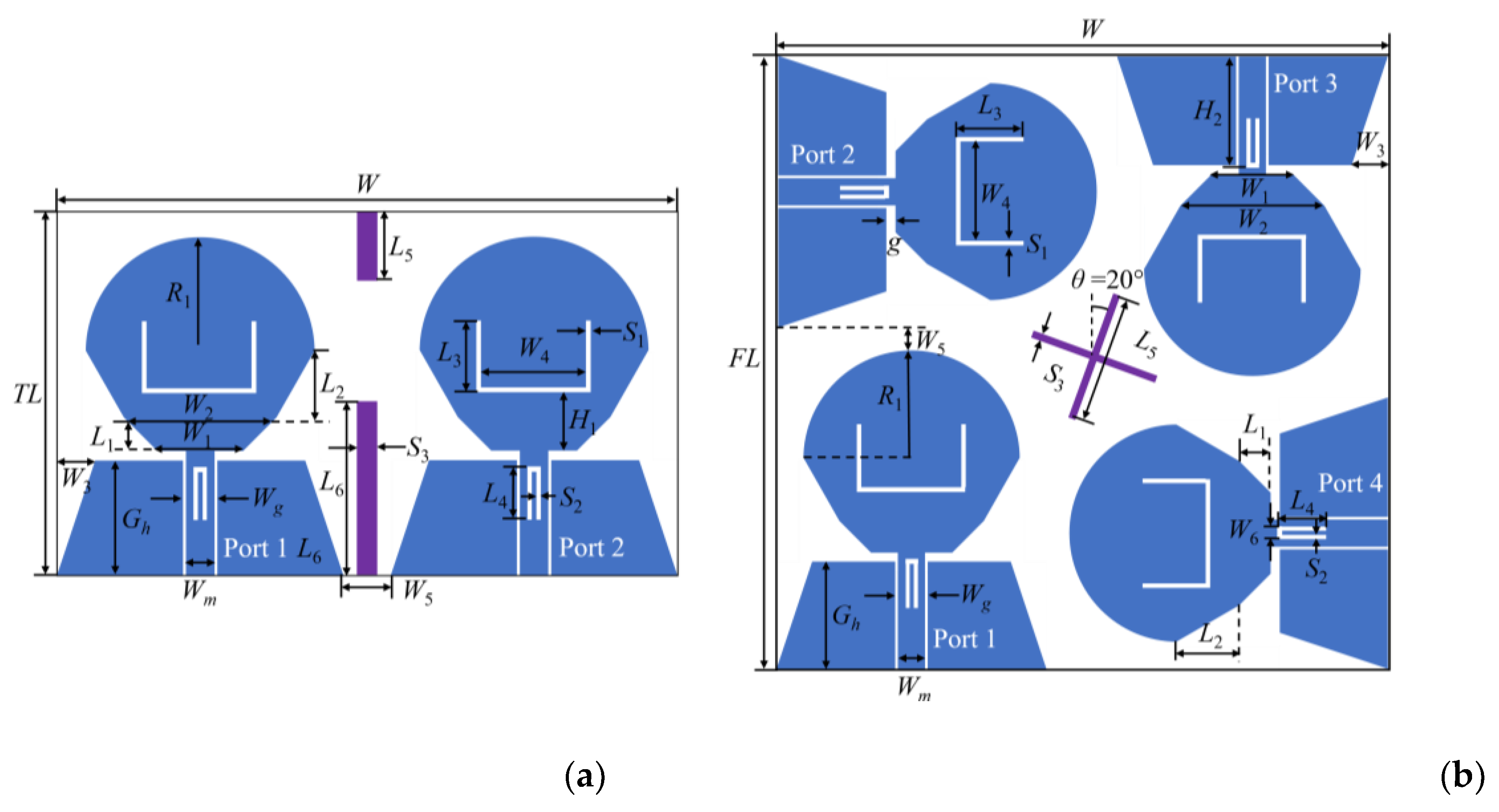
Figure 2.
Reflection coefficients of MIMO antenna elements with different numbers of notches.
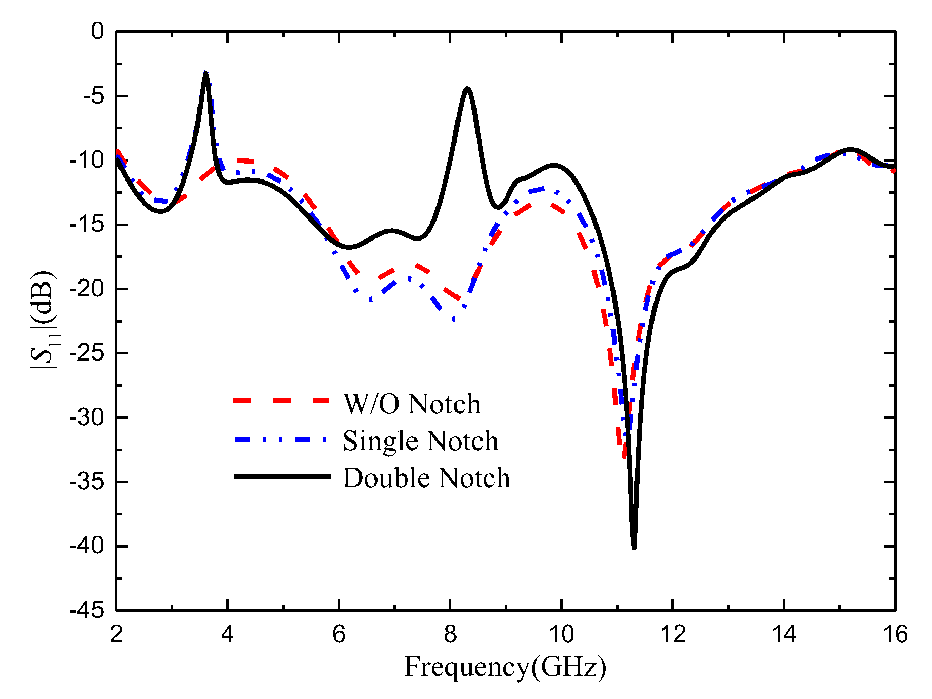
Figure 5.
Reflection coefficient of different L4 values
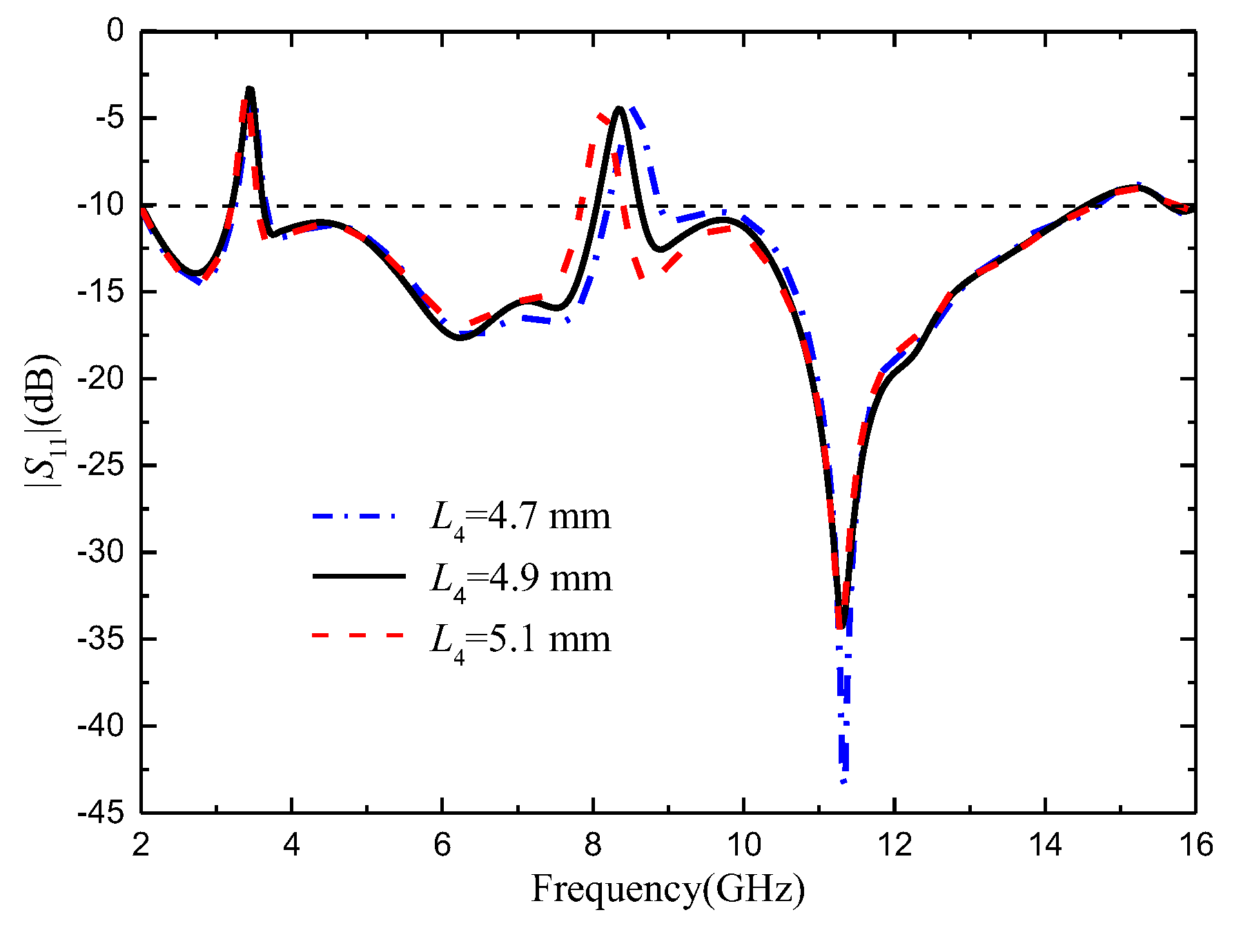
Figure 6.
Antenna surface current distribution at four frequency points: (a) 3.55 GHz; (b) 5.5 GHz; (c) 8.25 GHz; (d) 12.5 GHz.
Figure 6.
Antenna surface current distribution at four frequency points: (a) 3.55 GHz; (b) 5.5 GHz; (c) 8.25 GHz; (d) 12.5 GHz.
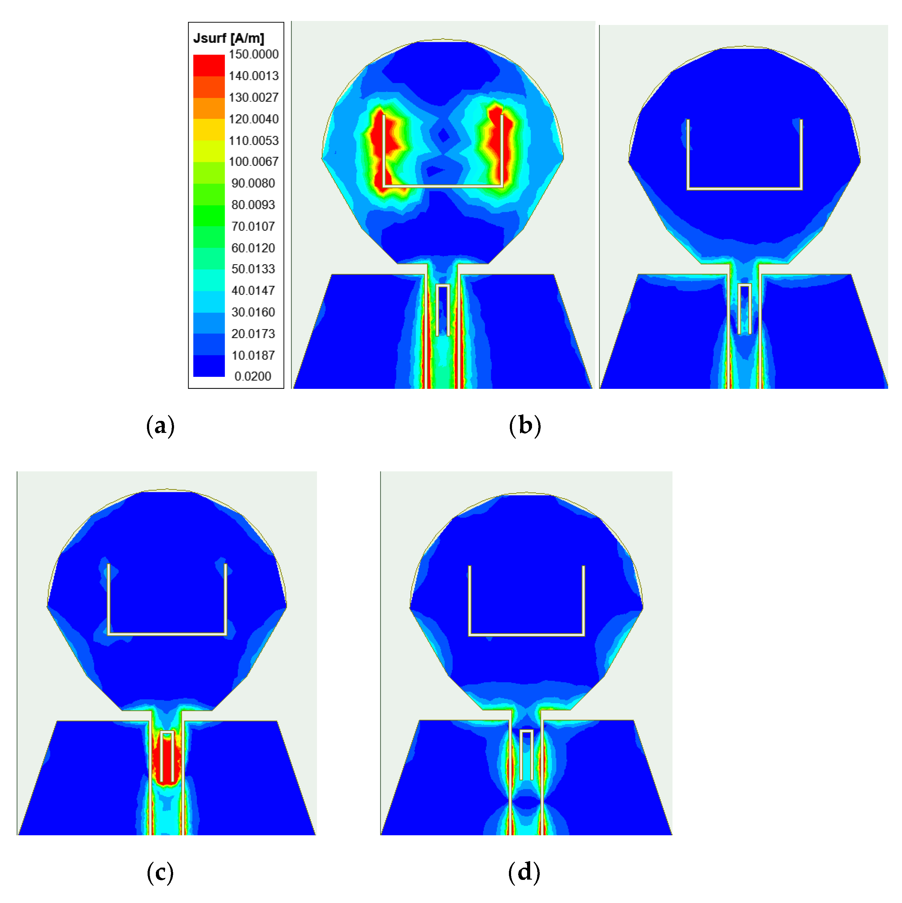
Figure 7.
The |S|-parameter with or without rectangular branches: (a) |S11|; (b) |S21|.
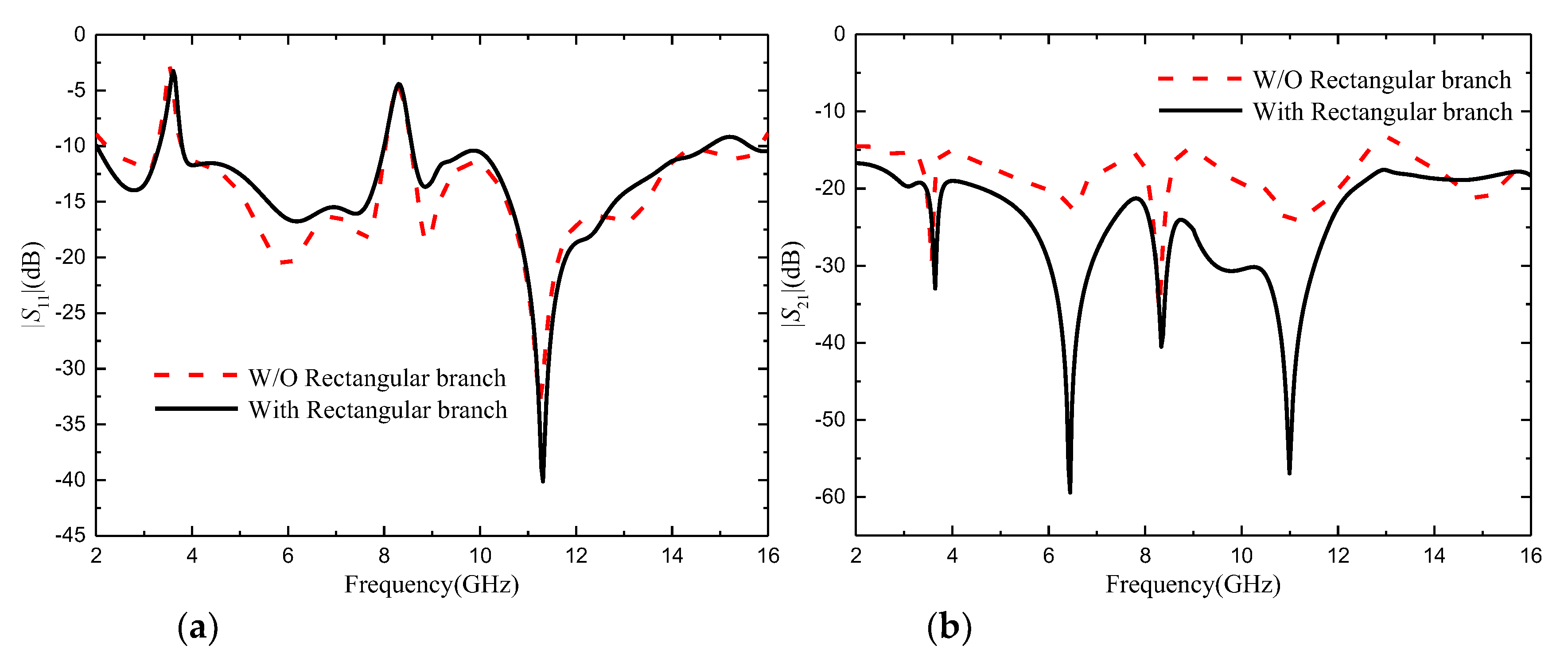
Figure 8.
|S|-parameter with different L6 values: (a) |S11|; (b) |S21|.
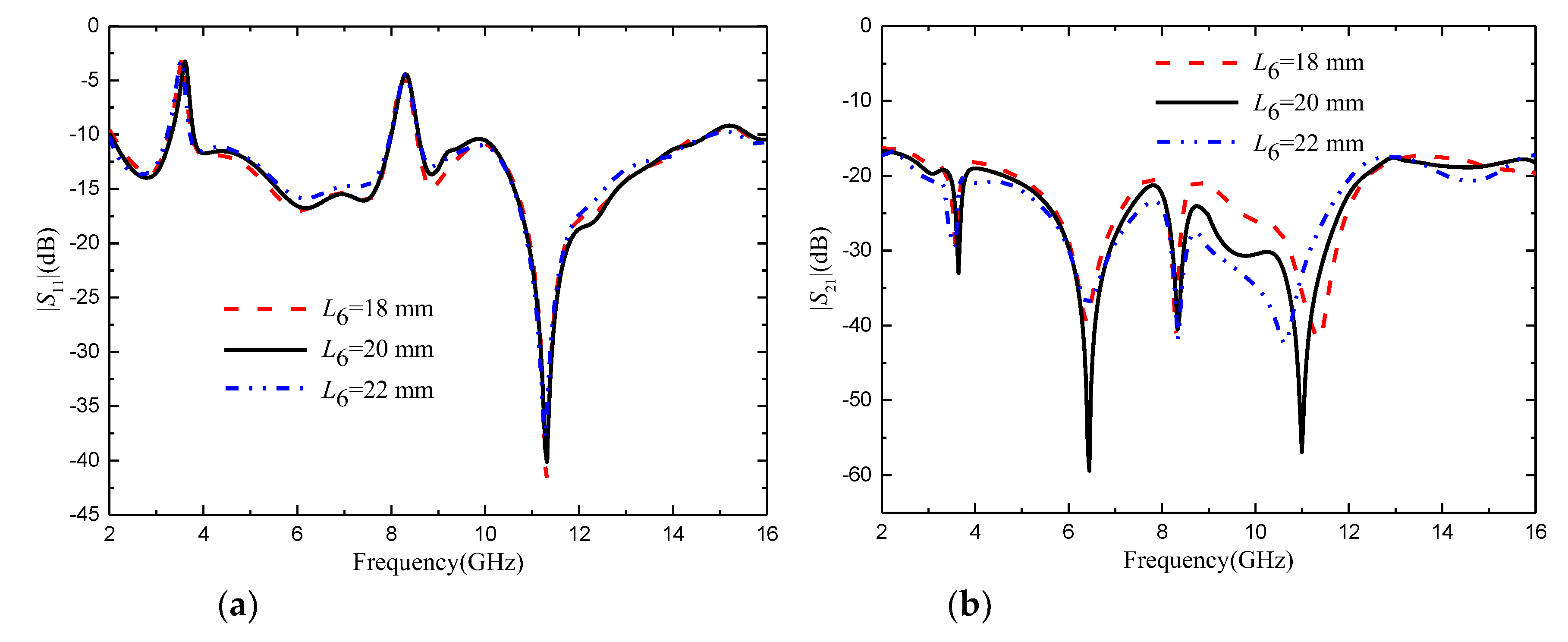
Figure 9.
Antenna surface current distribution at: (a) 3 GHz without adding rectangular branch; (b) 3 GHz with adding rectangular branch (c) 7.25 GHz without adding rectangular branch; (c) 7.25 GHz with adding rectangular branch; (e) 11.6 GHz without adding rectangular branch; (e) 11.6 GHz with adding rectangular branch.
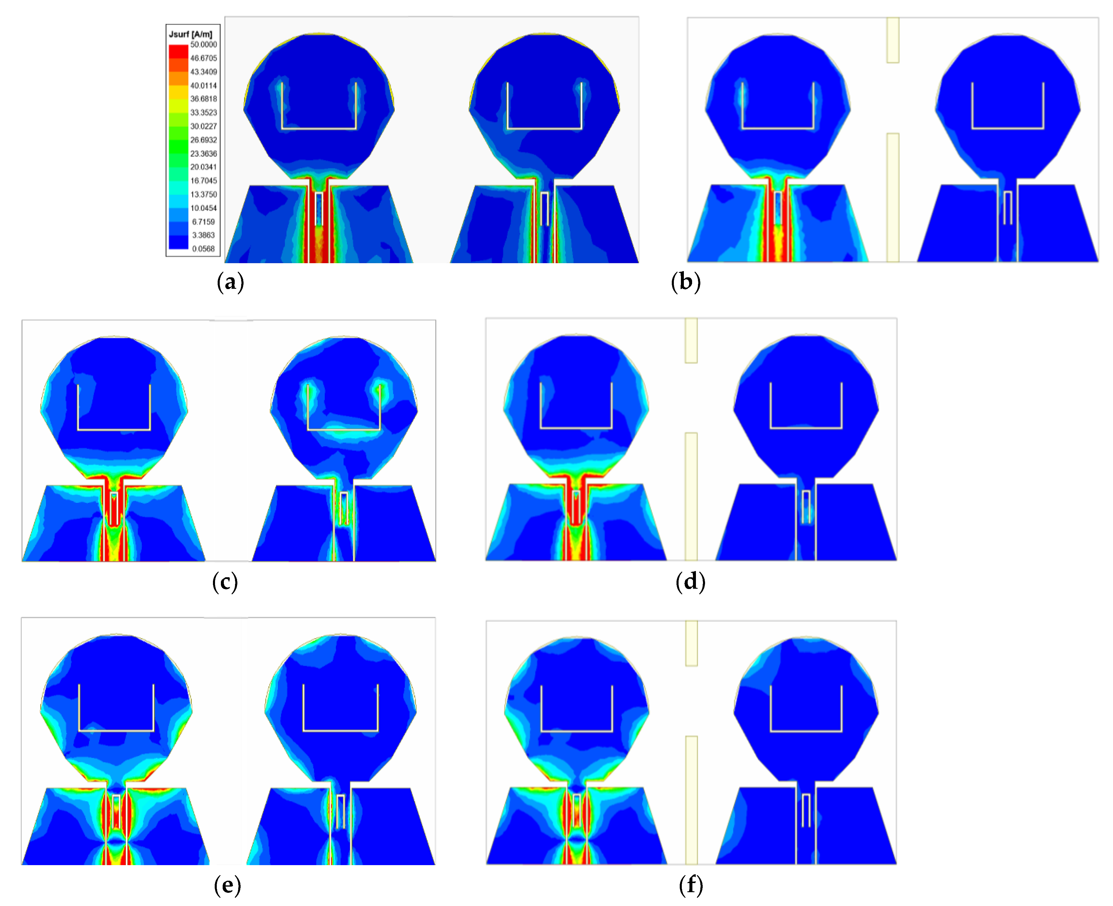
Figure 10.
|S|-parameters of the four-element MIMO antenna
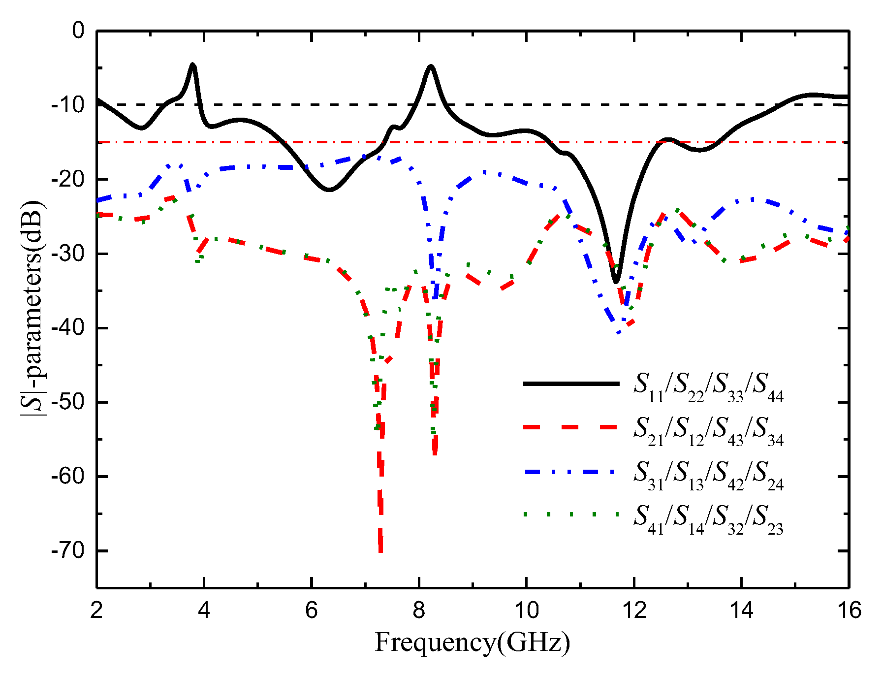
Figure 11.
The |S|-parameter of the four-element MIMO antenna with the cross branch
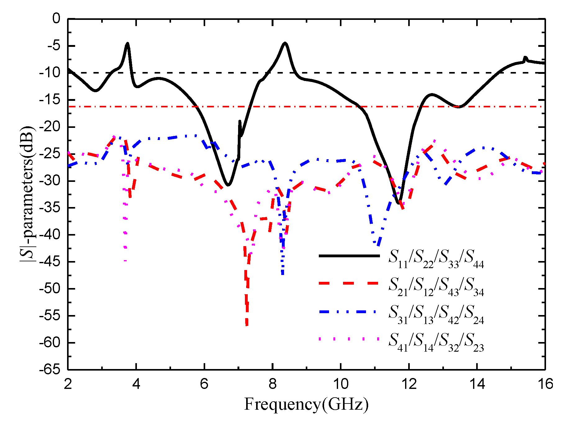
Figure 14.
Antenna surface current distribution at: (a) 4.5 GHz without adding cross-shaped branch; (b) 4.5 GHz with adding cross-shaped branch; (c) 7.25 GHz without adding cross-shaped branch; (d) 7.25 GHz with adding cross-shaped branch; (e) 11.6 GHz without adding cross-shaped branch; (e) 11.6 GHz with adding cross-shaped branch.
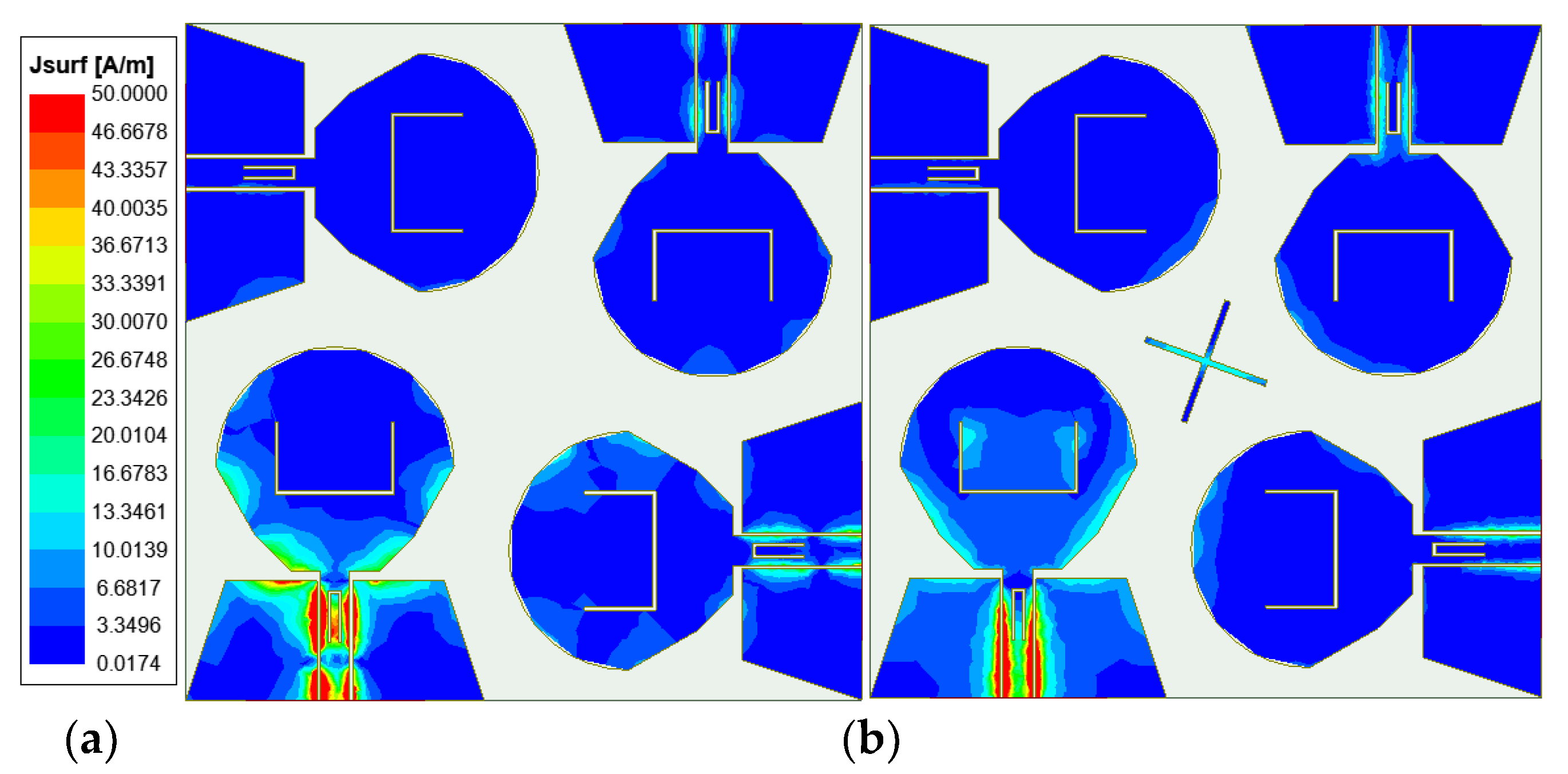
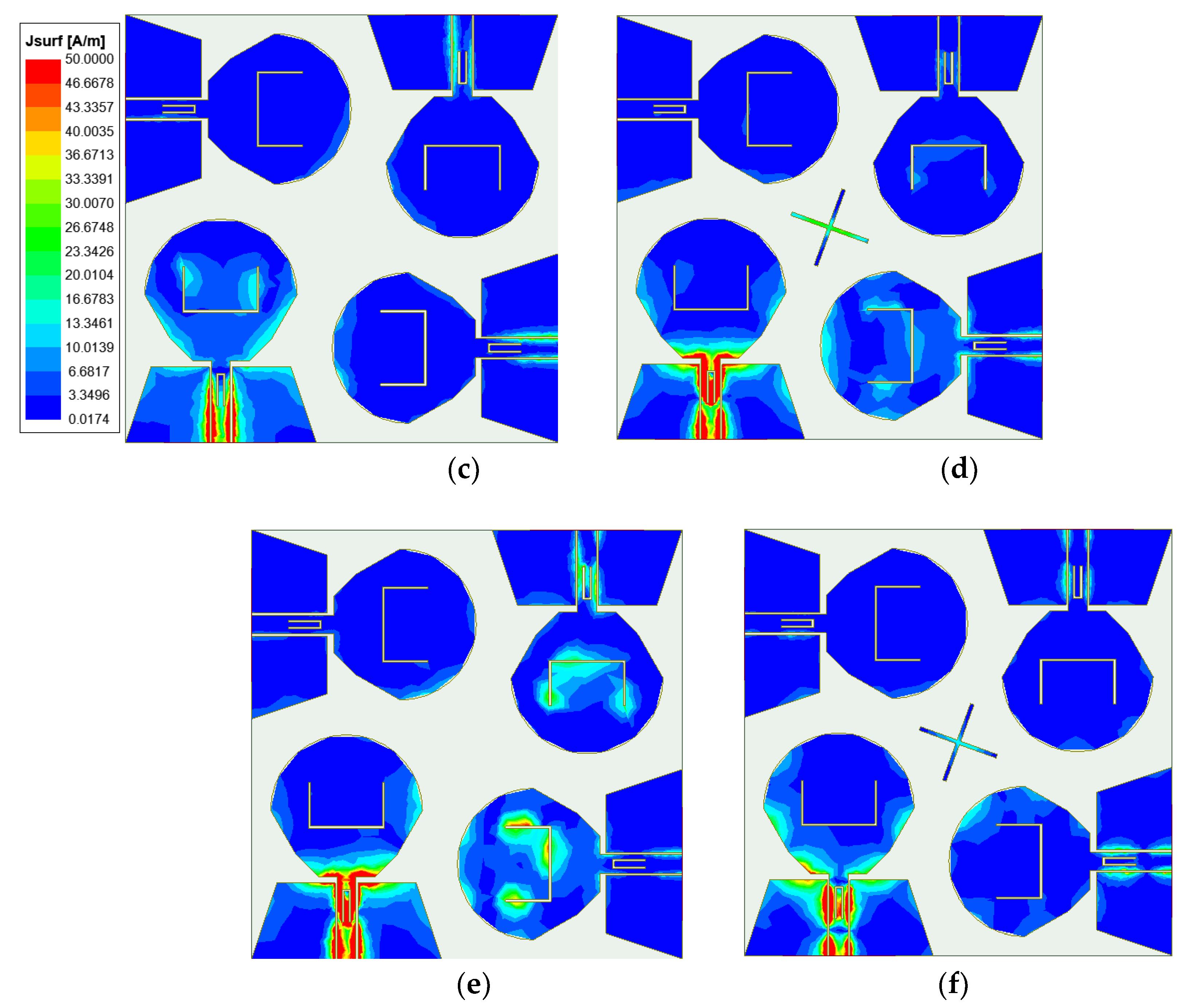
Figure 15.
Photographs of the measured |S|-parameter scenarios using vector network analyzer Keysight N5244A: (a) Two-element MIMO antenna; (b) Four-element MIMO antenna.
Figure 15.
Photographs of the measured |S|-parameter scenarios using vector network analyzer Keysight N5244A: (a) Two-element MIMO antenna; (b) Four-element MIMO antenna.
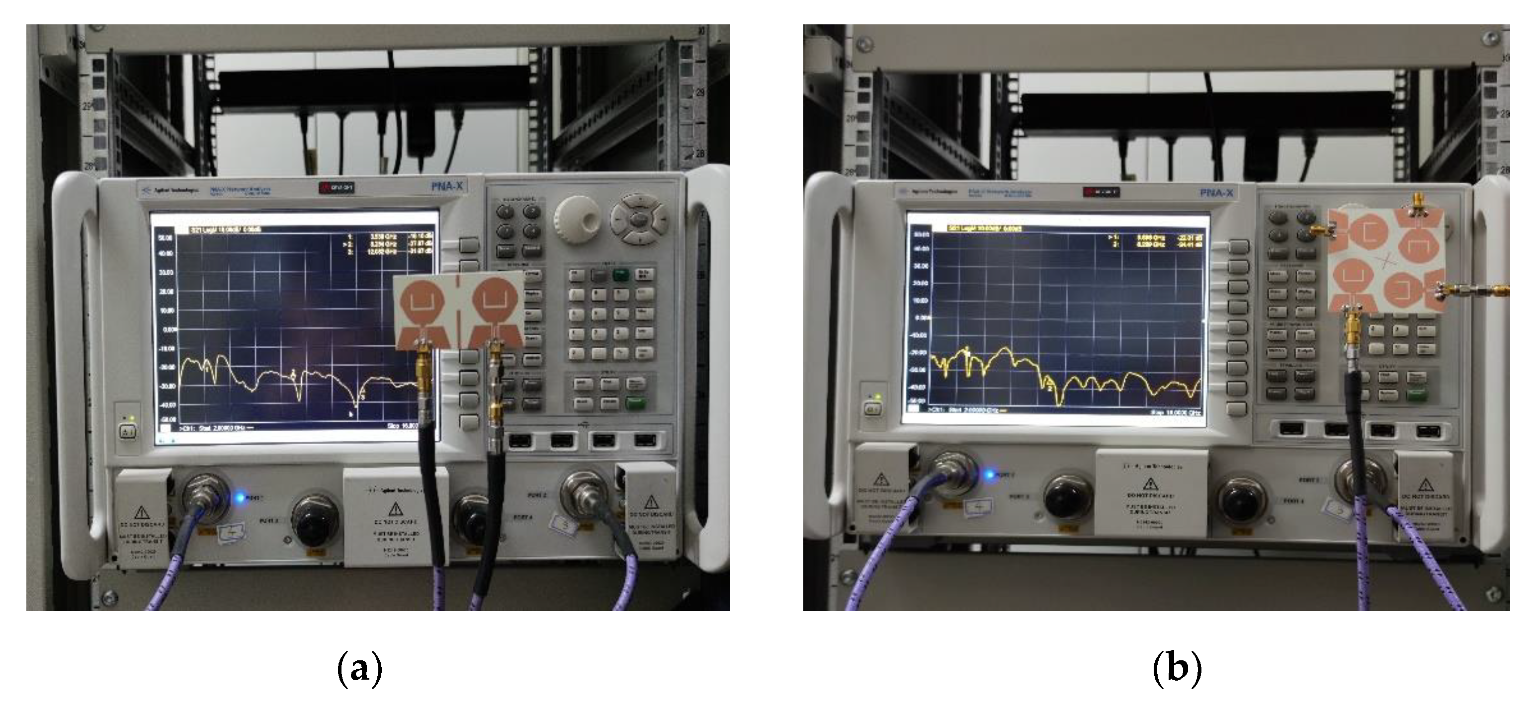
Figure 16.
Photographs of far-field radiation pattern measurements using a microwave anechoic chamber: (a) Two-element MIMO antenna; (b) Four-element MIMO antenna.
Figure 16.
Photographs of far-field radiation pattern measurements using a microwave anechoic chamber: (a) Two-element MIMO antenna; (b) Four-element MIMO antenna.
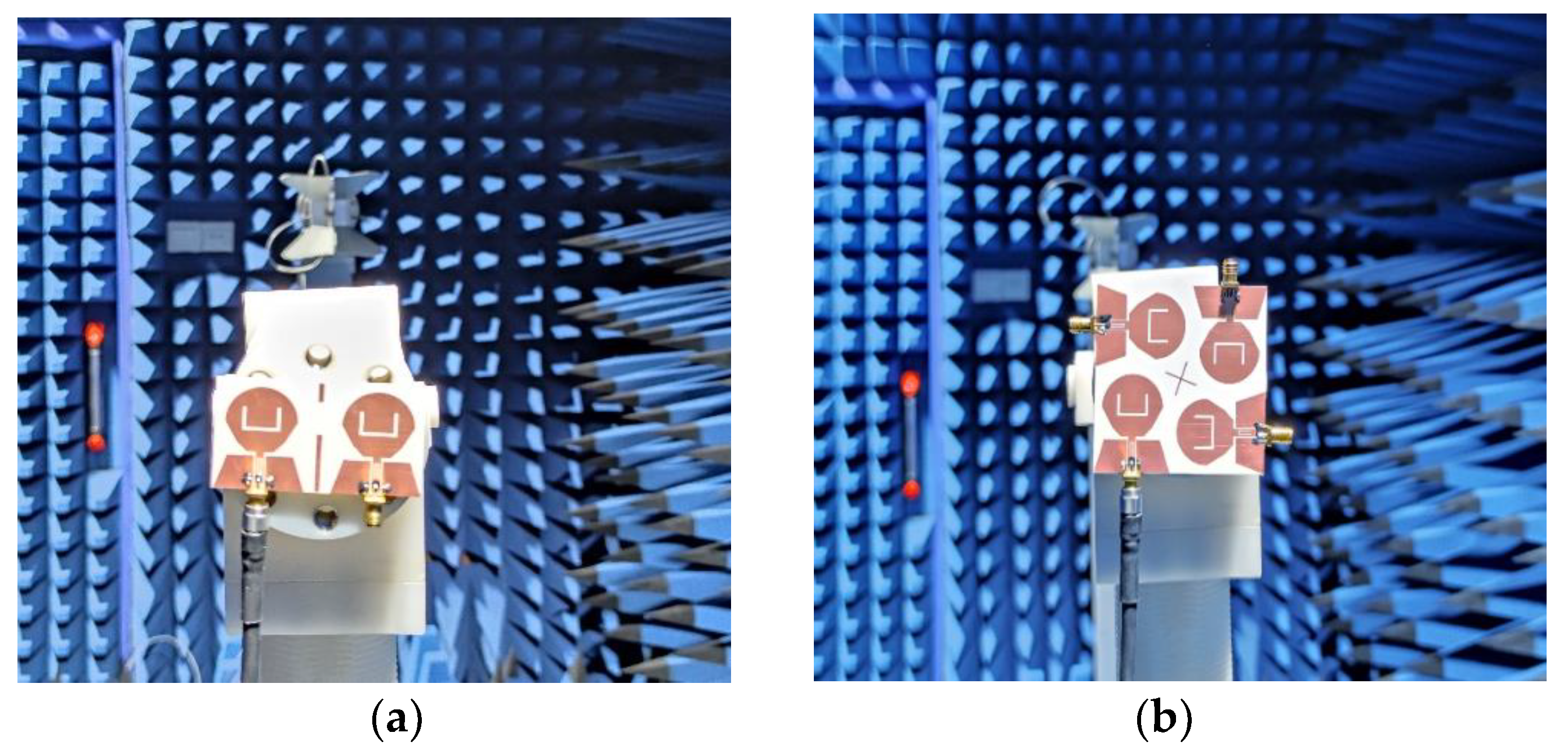
Figure 17.
Simulation and measured |S|-parameters of the proposed two-element MIMO antenna
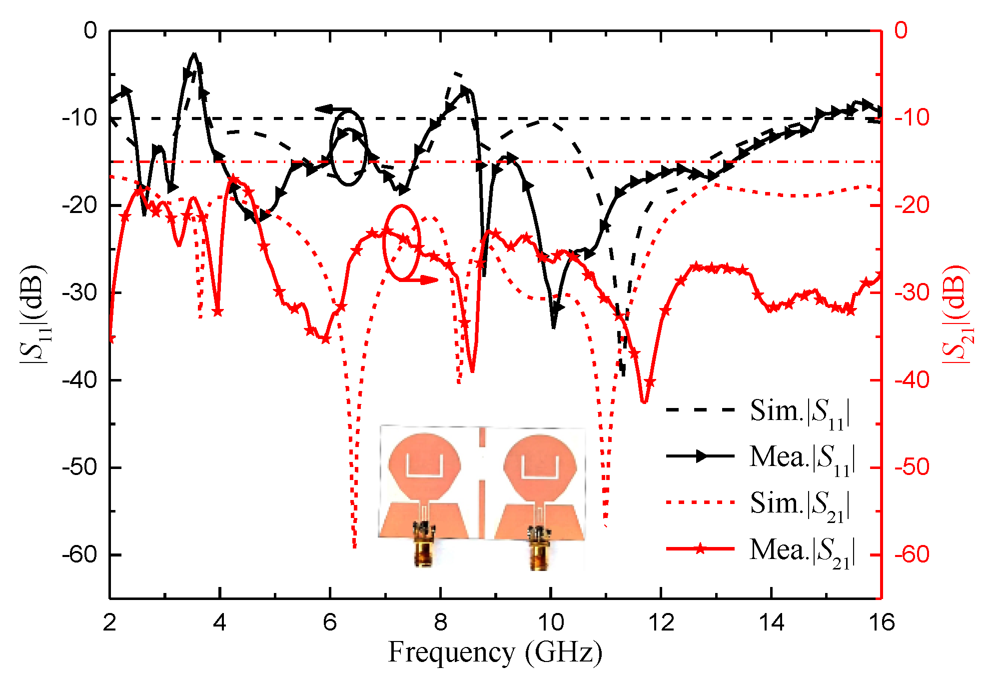
Figure 18.
Simulation and measured |S|-parameters of the proposed four-element MIMO antenna.
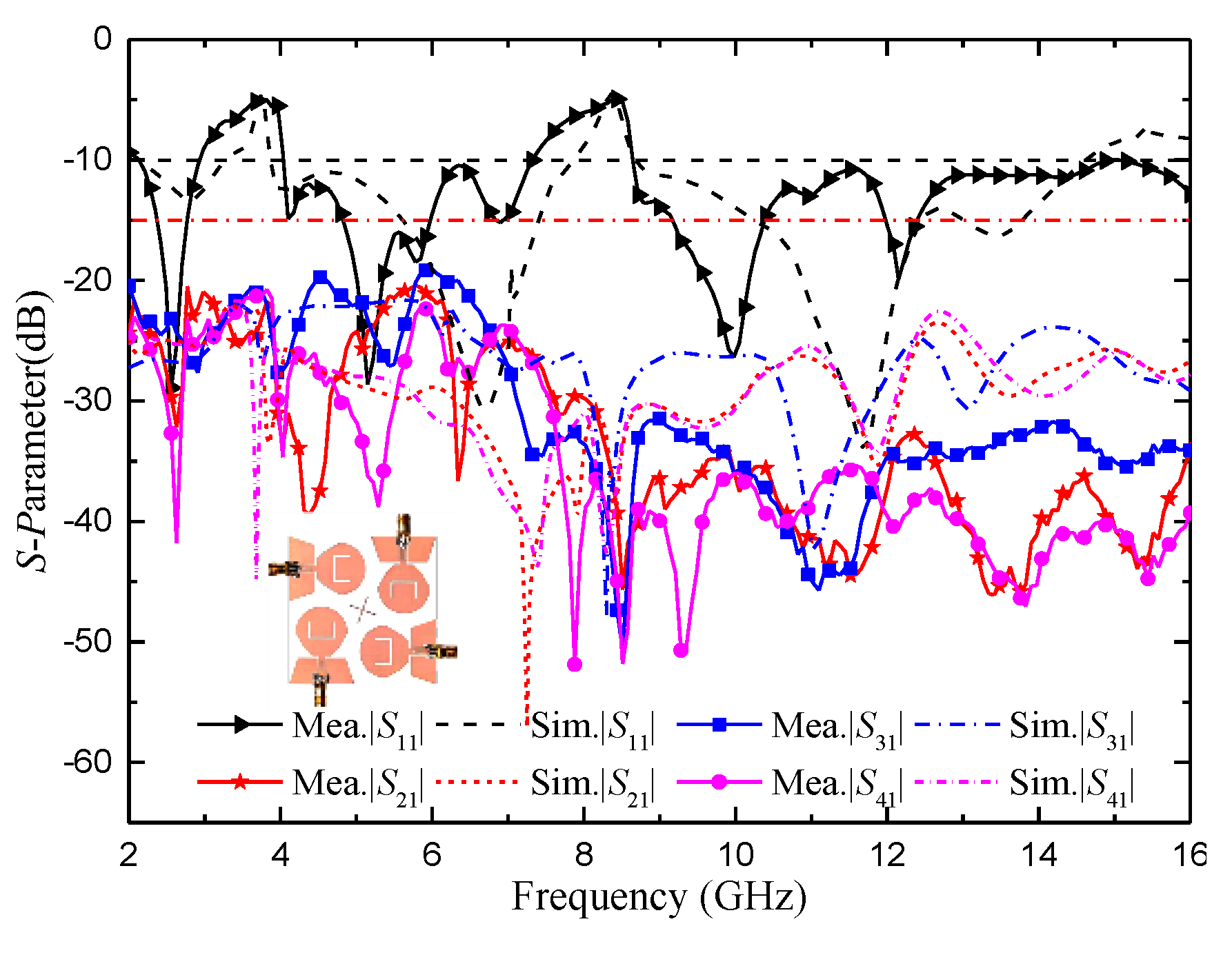
Figure 19.
The measured radiation pattern of the proposed two-element MIMO antenna: (a) 4.2 GHz; (b) 6.8 GHz; (c) 10.6 GHz.
Figure 19.
The measured radiation pattern of the proposed two-element MIMO antenna: (a) 4.2 GHz; (b) 6.8 GHz; (c) 10.6 GHz.
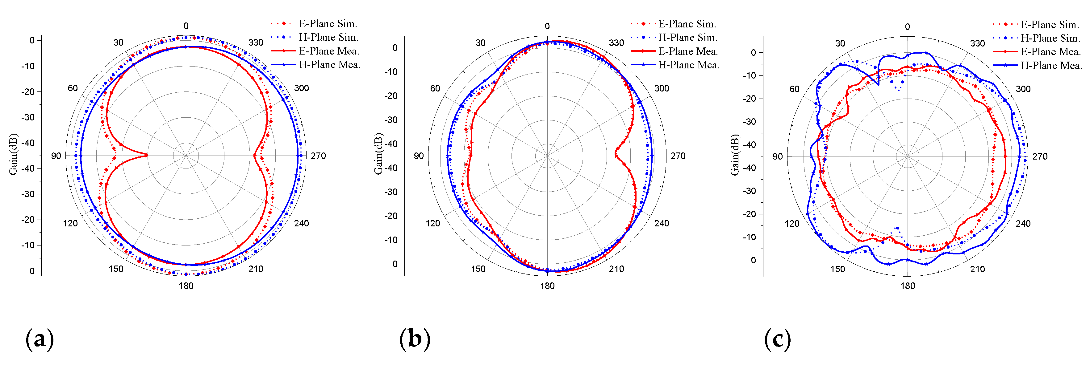
Figure 20.
The measured radiation pattern of the proposed four-element MIMO antenna: (a) 4.0 GHz; (b) 7.6 GHz; (c) 11.6 GHz.
Figure 20.
The measured radiation pattern of the proposed four-element MIMO antenna: (a) 4.0 GHz; (b) 7.6 GHz; (c) 11.6 GHz.

Figure 21.
ECC of the proposed antenna: (a) Two-element MIMO antenna; (b) Four-element MIMO antenna.
Figure 21.
ECC of the proposed antenna: (a) Two-element MIMO antenna; (b) Four-element MIMO antenna.
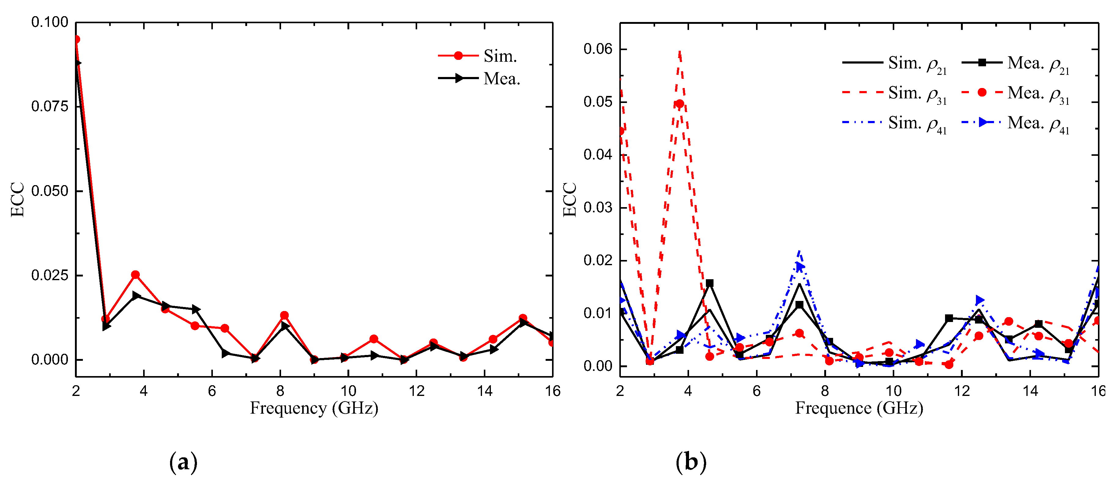
Figure 22.
DG of the proposed antenna: (a) Two-element MIMO antenna; (b) Four-element MIMO antenna.
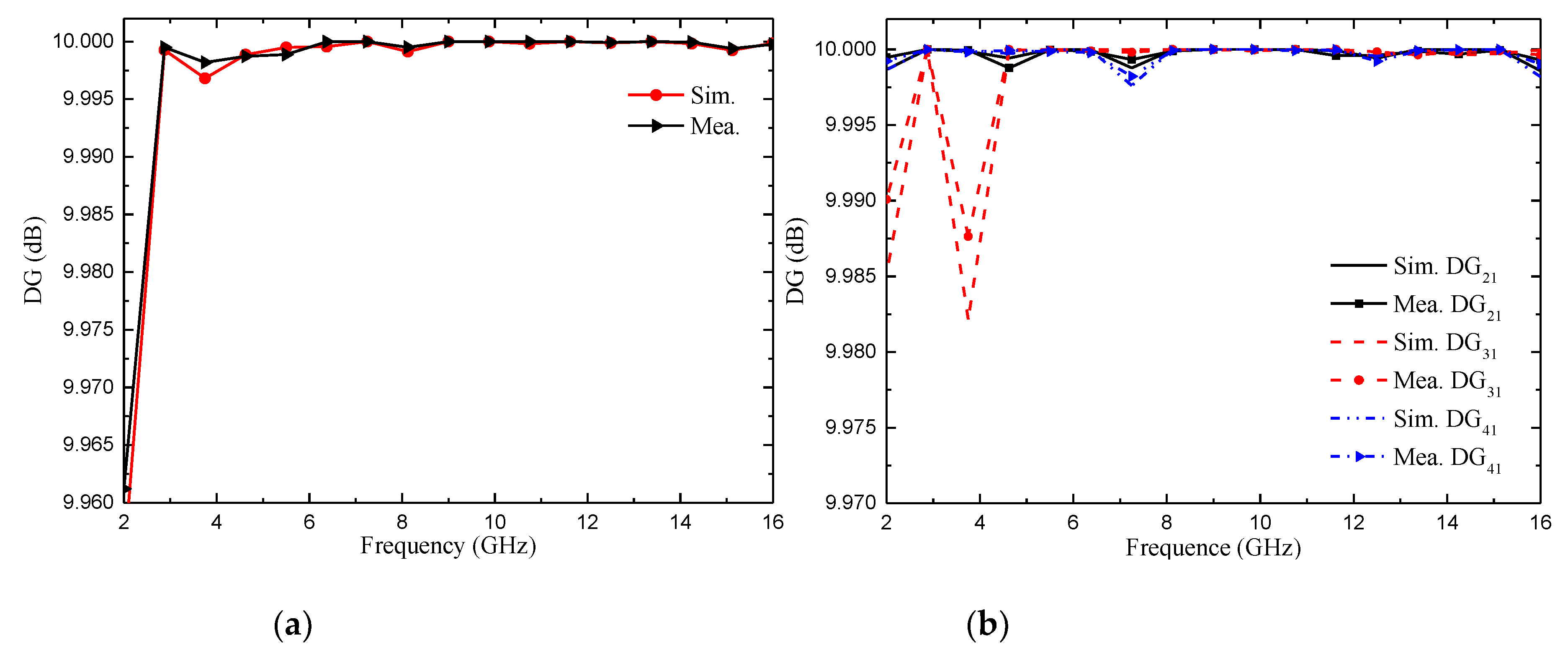
Figure 23.
Radiation efficiency of the proposed antenna.
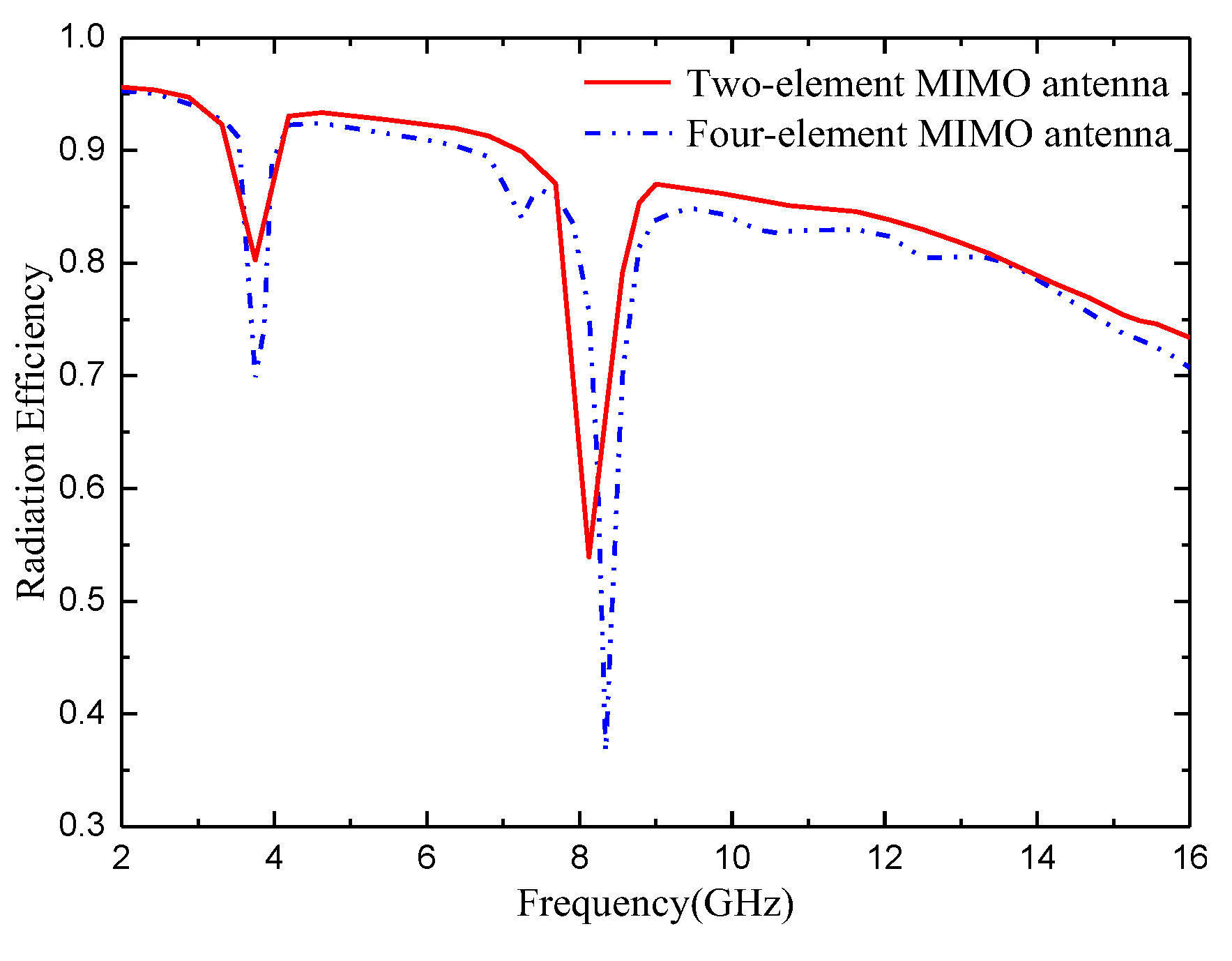

Table 1.
Antenna geometry (unit: mm).
| Parameter | TL | FL | W | H | H1 | W1 | W2 | W3 | W4 |
|---|---|---|---|---|---|---|---|---|---|
| Size | 38 | 68 | 68 | 1.6 | 7.6 | 9 | 16 | 4 | 11.4 |
| Parameter | W5 | W6 | W7 | L1 | L2 | L3 | L4 | L5 | L6 |
| Size | 8 | 1.4 | 1.5 | 3.5 | 7 | 7.2 | 5.2 | 7 | 20 |
| Parameter | L7 | S1 | S2 | S3 | S4 | g | Gh | R1 | H2 |
| Size | 14 | 0.3 | 0.3 | 2 | 0.6 | 1 | 12 | 12 | 11 |
Table 2.
Comparison of antennas in references and this paper.
| Ref. | Impedance bandwidth (GHz) |
Relative bandwidth (%) |
Number of elements |
Notch band |
Isolation (dB) |
ECC | Gain (dB) |
Radiation efficiency (%) |
|---|---|---|---|---|---|---|---|---|
| [12] | 4.3-15.63 | 114 | 2 | - | 20 | <0.0075 | <5.35 | >85 |
| [14] | 2.9-12 | 122 | 2 | - | 15 | <0.02 | <4.2 | >60 |
| [16] | 2.9-12.2 | 123 | 2 | - | 17.8 | - | <3.8 | - |
| [17] | 2.1-20 | 161 | 4 | WIMAX | 25 | <0.02 | <5.8 | >80 |
| [19] | 3.2-12 | 115 | 4 | - | 22 | <0.5 | <4 | >80 |
| [20] | 4.5-16.4 | 114 | 4 | - | 20 | <0.002 | <7.8 | >61 |
| This work | 2.45-14.88 | 143 | 2 |
WIMAX /ITU |
>17 | <0.02 | <5.7 | >82 |
| 2.14-14.95 | 150 | 4 |
WIMAX /ITU |
>20 | <0.02 | <5.9 | >80 |
Disclaimer/Publisher’s Note: The statements, opinions and data contained in all publications are solely those of the individual author(s) and contributor(s) and not of MDPI and/or the editor(s). MDPI and/or the editor(s) disclaim responsibility for any injury to people or property resulting from any ideas, methods, instructions or products referred to in the content. |
© 2023 by the authors. Licensee MDPI, Basel, Switzerland. This article is an open access article distributed under the terms and conditions of the Creative Commons Attribution (CC BY) license (http://creativecommons.org/licenses/by/4.0/).
Copyright: This open access article is published under a Creative Commons CC BY 4.0 license, which permit the free download, distribution, and reuse, provided that the author and preprint are cited in any reuse.


