
Submitted:
02 March 2023
Posted:
03 March 2023
You are already at the latest version
Abstract
Power generation using renewable technologies has become a primordial option to satisfy the energy demand all over the world, being solar concentrating technologies widely applied for this purpose. A combination of Parabolic Trough Collector with Direct Steam Generation has been considered an excellent option for power generation, due to the economic cost and complexity in the plant are reduced. The thermal evaluation of the solar power plant as well as the PTC in the DSG process is very important in viability and economic analysis. In this sense, as the main objective of this work, a numerical tool for evaluating DSG with PTC technology has been developed. The software SOLEEC is a versatile, reliable, accurate and friendly to the user for thermally evaluating a DSG with PTC technology. The user has the possibility to compare the thermal behavior of different geometrical dimensions for a PTC; and even consider different materials; in order to satisfy the demand of superheated steam by a DSG process. The software has an error less than 5% when compared with literature results and in this paper is used to evaluate a power plant in Mexico obtaining that the change to DSG proposing different PTC could reduce the solar field about 35%.
Keywords:
PTC
; DSG
; solar energy
; power plant
1. Introduction
The solar power plants based on Parabolic Trough Solar Collectors (PTC) have been under study and with constant improvements in the last years, due to the fact that PTC technology is one of the most mature devices to convert the incident solar irradiation into sensible heat through a heat transfer fluid, this kind of devices can be used individually or combined to form different arrays. The application for electrical power generations is mainly through solar power plants or as auxiliary systems in an integrated combined cycle power plant.
The concentrating solar thermal systems have been introduced as solar technologies for electrical power generation by heating a working fluid to high operating temperature range, normally up to in combination with a thermodynamic power cycle, the prediction and analysis could be developed using a simulation tool, such as Mathcad that can be used for a pre-design, some results show that in summer months the power plant capacity can be increased up to around 50 MW reducing the carbon dioxide emission [1].
Solar power plants based on parabolic trough solar collectors can be used as auxiliary systems for Combined cycle power plants to improve the overall efficiency, different plants using this technology have been installed around the world with excellent results, such as Kurymat plant, installed at Cairo, Egypt, in that plant, the exit gasses from the gas turbine are used to produce superheated steam into a steam turbine without any supplementary energy. The plant was modelled and numerically simulated using the software TRNSYS, the steam turbine produces 52 MW which is about 44% of the total power generated by the entire plant [2].
The configuration of the power generation systems is also an important aspect, such as a solar collector used to supply the heat for a two-stage steam turbine with inter heating and an Organic Rankine cycle, this system was simulated and optimized using the PSO algorithm with a combination of the EES and MATLAB. The PSO algorithm select the best designing variables, the results show that 59% of the total exergy destruction happens on the solar collector [3].
A model based on an energy balance in the solar collectors is used to determine the main operative parameters of a typical power plant. The simulation considers forced convection inside the solar absorber tube and the model was verified using heat data from a Solar Thermal Power Plant located in Spain. The heat generated in similar conditions of the solar collector in the region with a temperature climate, in the city of Bialystok, Poland was determined by the model for different months of the year. The results show that the energy obtained from the same area of concentrated solar collectors is eight times lower compared to the installation of Spain [4].
Other work investigates the performance of a conventional steam power plant retrofitted with a solar-assisted regenerative system using Parabolic trough solar collectors, the steam power plant is located in Kuwait receiving high solar radiation levels. The results show that removing the low-pressure turbine extractions enhance the performance of the solar power plant by 9.8 MW and with an aperture area of , also a techno-economic analysis was used to estimate the levelized cost of energy, this power plant compared to a conventional photovoltaic solar plant reduces the total aperture area to 45% and 44% [5].
Also, the study of solar power plants is being extended to places where the climate effects existing in the zone make it hard to study, such as the potential of power production in Adventdalen, Svalbard, this study shows that snow drifts pose a significant challenge for solar power plants, due to the fact that they can grow to cover the plant, resulting in reducing the power produced and the imposed of a mechanical load to the array. The results of solar power production indicate that the module yield is enhanced by the low ambient temperatures and the Polar climate enhance the module performance [6].
In this paper, the thermal evaluation of the solar power plant by means of a numerical tool for evaluating DSG with PTC technology is developed. At the end the user has the possibility to compare the thermal behavior of different geometrical dimensions for a PTC; and even consider different materials; to satisfy the demand of superheated steam by a DSG process and substitute the actual configuration of a CCPT in Mexico that uses PTC field with a synthetic oil to get the steam saturated conditions.
2. Materials and Methods
PTC collector is a solar device used to convert the irradiation solar energy reached on the collector’s aperture into heat energy absorbed by a heat transfer fluid (HTF) which is flowing inside the absorber tube, the amount of heat available is increased due to the optical and geometrical configuration.
2.1. PTC and DSG generation
The performance of a PTC depends on the construction material as well as the geometrical dimensions. A high reflectivity is required for the parabolic surface to reflect the incident radiant energy towards the absorber pipe that should be an excellent heat conductor and it is covered up with a coating paint to obtain a selective surface, reduce energy loss, and improve the conversion process by supplying the maximum of energy to the HTF or working substance. Sometimes, the absorber pipe is enveloped by a transparent cover to reduce the heat convection to the surroundings, in this sense the transparent cover must have a high value of transmittance and low absorptance. Resistance to the thermal stresses is another quality for the construction material due to the high temperature gradients found in the PTC systems.
The PTC technology has a amply application range; from low temperature applications to high temperature ones. For low temperature applications, the HTF does not experiment a phase change and many devices use water as working fluid. The maximum temperature reached is below the saturation point and the applications are mainly for heating water in hospitals, hotels, swimming pools or small applications for industry uses, mainly for heating water. When higher temperatures are required the applications of thermal oils for HTF in the PTC is commonly used and the temperature reached are around the 400°C [7]. However, the addition of a heat exchanger is required for steam generation. This last step increases the cost in the installations and generated loss of energy in the heat transfer process, in several cases the implementation of these devices for power generation increases the cost of the thermal plant and complicates the configuration of it, as a result, its implementations becomes prohibitive.
Recently, many devices and technological configurations have been under study to get steam directly (DSG) from the absorber tube. Three different configurations have been studied. The first one is once trough, where the water entering is turned into steam in the same pipeline of the absorber. A second one is recirculation mode; in this case; a drop separator is installed between the saturated steam section and the superheated steam; the separator returns the liquid water to the inlet of the collector. Finally, the third option is the injection mode, where the absorber tube is divided into many stretches and an injection valve is installed at the start of every section [8]. The most studied configuration is the once trough, due to a less complexity on the installation. The principal point of DSG generation is a cost reduction and to avoid the need of heat exchangers between the solar collector and the steam turbine, on the other hand, some problems are presented during the steam generation because the flow stratification in the absorber tube induces strong thermal stresses and in some cases a deformation, leaks, and severe damage in the absorber tube of the PTC collector are presented.
The next section shows the mathematical models for the heat transfer along the absorber pipe that will be used in the software for computing the heat coefficients in the PTC collectors.
3. Mathematical Model
DSG generation based on parabolic trough solar collectors can be simplified for analysis as horizontal pipes with a constant heat flux at the outer boundary while in the interior a forced evaporation phenomenon is developing. The evaporative process can be divided in three different heating zones: saturated liquid where the temperature is less than the saturation liquid temperature when the fluid enters the absorber, then the steam generation zone where the fluid goes through several flow patrons until reach the saturated steam condition. Finally, the reheating zone, where the steam reaches the steam desired condition. In the first and last heating zones, the HTF will be considered as one phase fully developed fluid. The HTF goes into the collector at subcooled fluid and when passing through the collector, the fluid temperature and wall temperature increase in the flow direction and the mean temperature can be computed by means of an energy balance in the axial direction. Similarly, once the HTF has become a steam, it will be treated as a one phase fluid. This zone is critical because as the heat flux remains constant at the boundary, and the sudden diminution in the heat transfer coefficient carries a sudden increasing in the wall temperature than can caused severe damage in the duct. Several studies consider that this critical situation is because the liquid film in the annular regime is evaporated because the heating flux conditions in the wall [9].
In the zones 1 and 3, the heat transfer coefficient will be computed using the classical model for fully developed flow in one phase for circular pipes. The heat transfer coefficient for fully developed flow in pipes depends on the flow regime and in the heat imposed on the pipe wall as boundary. For turbulent regime, the Nusselt is a function of the Reynolds, the Prandtl and the friction factor. Gnielinski developed a correlation valid for several Reynolds including the transition zone with a maximum of 10% error when compared with experimental data [10].
In the evaporative zone or changing phase zone the liquid and steam are at saturation conditions and the heat at the wall produces the latent thermal energy for the evaporation process. Here the assumptions of horizontal smooth pipe will be applied. The flow patterns and the heat transfer are function of the temperature differences between the wall and the fluid saturation temperature as well as the fluid properties.
The heat radiant energy supplied to/captured by the receiver pipe induces changes in the flow going from saturated liquid to saturated steam. The flow goes through different patterns as those showed in Figure 1. As the mass flow is higher the flow pattern is more symmetric and stable as happened in vertical ducts. In this sense, a high mass flow would be recommended by the PTC operation.
There are several correlations in the literature related to the evaporative forced convective heat transfer. Chen´s correlation is the most used when water is considered, Chen (1966) used more than 600 experimental data for water in a vertical duct [12]. The approximation is good for water at low pressure but is not suitable for thermal oils or refrigerants. Gungor and Winterton combines the models of Chen and Shah, while Liu and Winterton (1991) showed a correlation based on more than ten thousand data for water, refrigerants and cryogenic substances [9,13,14]. The data are suitable for a huge variety of density relations for the liquid and vapor phases as well as different heat flux and mass flows. The effect for density and boiling number are critical for the computation. He presented a simple model for the convective effects and the nucleation introducing an additional parameter for taking in account the effects of the fluid surface and the nucleate boiling dominant region and the convective boiling dominant region based on the convective number, boiling number and Froude number. The heat transfer is computed by the addition of the following equations:
where NBD and CBD refer to nucleate boiling dominant and convective boiling dominant respectively. The dimensionless parameters are the convective number (Co), the boiling number (Bo) and the Froude number (Fo):
The Froude multiplier for horizontal smooth pipes is defined as:
The heat transfer coefficient for the liquid phase is computed according the Gnielinski correlation (1976) for and .
But, for y , the Petukhov and Popov (1963) is used:
The friction factor is computed by the equation (2.36):
according to Kandlikar (1999) is equal to unity for water.
4. Numerical Methodology
The software SOLEEC was codified to run in MATLAB platform. The reason of this choice is because the huge quantity of operations and the versatility of the MATLAB for process the vectorial arrays, as well as the easiness to develop graphic interfaces.
For a DSG with PTC designing, the absorber pipe can be considered to be horizontal and the energy uniform along the pipe. The water at the inlet with a temperature lower than the saturation temperature for a given pressure will increases until reach the saturation point, then starts the phase change; first the nucleation and after the steam quality going increasing and the different several flow patterns occur as the evaporative convection is presented. The heat transfer coefficient in the phase change is influenced by the bubble generation and the liquid film on the wall. The saturated water is completely converted into steam and the heat coefficient is reduced. The maximum in the heat transfer coefficient is found in the change of phase, when the steam quality reaches the value of x=0.8 [15].
The numerical methodology considered in the SOLEEC for computing the conditions from saturated water to super heating steam at the pressure given was divided in three parts for easiness. First, the preheating util reach the saturation point, the second one is the evaporative section where the change from liquid to steam is given and finally the superheating zone. Each zone is treated with different mathematical model because in fact the HTF is changing and have different properties thus, the mathematical model has to be the appropriate one to calculate the heat transfer and pressure drop.
Figure 2.
Sections in the absorber pipe in the DSG: preheating zone (liquid phase), evaporative zone (two-phase flow) and superheating zone (steam). The flow is from left to right. The letter x represents the steam quality.
Figure 2.
Sections in the absorber pipe in the DSG: preheating zone (liquid phase), evaporative zone (two-phase flow) and superheating zone (steam). The flow is from left to right. The letter x represents the steam quality.
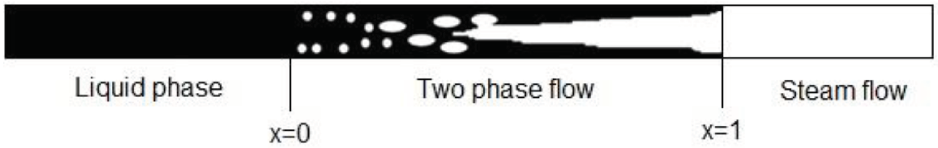
The preheating is the first part of the absorber pipe. At the inlet the water is at a temperature close to the ambient and at the exit the saturation point for the given pressure should be reach. With the mass flux (kg/s) and the heat supply it can be computed the length of the pipe for this zone. The software makes the required interpolations for compute the thermal properties considering the flow is a one phase flow or liquid phase [16]. Once the saturated temperature is reached, it starts the evaporation or forced evaporation. The substance stars as liquid and at the exit we find saturated steam. In this zone, the pressure and temperature are constants for the mass flow previously computed. Here, the heat transfer coefficient and the pressure drop are the most important parameters to define, and the models for nucleating and the flow patterns are used for the correct computation.
In the last section the superheating process is considered. At the inlet the flow is a saturated steam and at the end of the absorber pipe a superheating steam at the temperature and pressure desired. The flow mass remains constant from the other sections and been considered as fully developed flow and the mathematical models are those of one phase flow while the software does doble interpolated values for the properties for every point.
SOLEEC software is a computational tool for designing and evaluating DSG systems. The software allows the evaluation of the solar resource for any locality and then by means a succession of different windows the software allows the computing and evaluation of different geometrical dimensions for a DSG. In this sense, the software gives complete information of the thermal behavior of different PTC that according to the energy requirements can supply the thermal demand considering the meteorological data and the solar energy supply. In a first stage, the software was planned for no phase change systems, but in an upgrade the computing subroutines were introduced for considering the two-phase flow and the steam generation, the result is a robust, versatile, and complete numerical tool for the analysis these systems.
The principal advantage of the software SOLEEC is its ability to considerer different PTC's geometrical dimensions as well as different materials (Table 1). The user can execute the program and make the comparison in order to choose the best combination of parameters to supply the energy demand required. This is numerical tool have become an auxiliary option for analyzing and designing thermal devices or thermal equipment because several combinations of the different variables can be analyzed at low cost and at the end it is possible to choose the combinations of parameters that give the maximum efficiency and the best thermal behavior.
Figure 3 shows the main menu of the SOLEEC software. In the upper section, the user can select for the evaluation of the solar resource, in the lower part, the user can choose between designing a PTC without phase change or designing a DSG system. In both of these options the user can choose between a one-month evaluation or compute the evaluation for all the year. In the first, the evaluation is for a specific month of the year, meanwhile in the second option, the evaluation is for twelve months. Once the choice is made, the software executes in order to show the calculated values in another interface window as it can be seen in Figure 4. The input data are solar irradiance, incident angle, air velocity, ambient temperature, pressure, temperature at the inlet and at the outlet of the PTC. Here, the user has the option to choose between some construction materials for the PTC, as reflective surface, selective surface, material for exterior cover. Once it’s executed, the software will give the geometrical parameters of the PTC parabola radii, focal length, lengths for each section, mass flow to produce the steam at the needed conditions as well as some thermodynamics values as heat gain, heat lost and thermal efficiency. In addition, the software allows to export the computed values organized in tables for text format and shows some charts for an easy understanding in the designing process.
The reliability, accuracy and precision of every numerical tool must be proved by means of experimental data or published results of other authors. In this sense, the SOLEEC software was validated with several papers and textbooks. The validation process and description can be consulted in the reference [17].
5. Results
The combined cycle power plant 171 CC Agua Prieta II, is conditioned with PTC that produce the steam mass flow at the temperature and pressure conditions, generating 14 MW. Agua Prieta, Sonora, is located at the North of Mexico, Latitude of 31.31°N and Longitude of 109.53°W, predominating a desertic climate, meaning that it is an excellent place for installing solar thermal systems, due to the huge quantity of solar radiation availability.
The inclusion of this solar field for steam generation using renewable energies diminishes the fossil fuel (natural gas) consumption, impacting positively the decrease of the greenhouse effect gases, avoiding the emission of 17760 tons of carbon dioxide (CO2) per year. The solar field installed in the power plant uses 277 tons of synthetic oil as heat transfer fluid (HTF) reaching temperatures closed to 500 °. The HTF is pumped across the heat exchangers located in the Combined Cycle Power Plant (CCPT) to produce saturated steam. The operative conditions of the solar field in the CCPT are summarized in Table 2.
The solar-gas hybrid power plant in Agua Prieta II Sonora, consists of 34944 mirrors and 3744 absorber tubes distributed in 26 rows. Each row is composed by 4 PTC and each PTC has a length of 150 m. The solar field aperture is 300000 m2 and the total area of the solar field is about 600000 m2. The PTC rows are North-South oriented and an electromechanics positioner one-axis system allows the East-West rotation to diminish the solar irradiance incident angle and make a better use of the solar resource. A schematic diagram of the Integrated Solar Combined Cycle power plant, Agua Prieta II is shown in the Figure 5.
It should be understood that the operative conditions for the solar field of the CCPT requires a saturated steam at 330°C and at 130 bar, that means that, the heat for superheat the steam is provided from the exhausted hot gases from the gas turbine. The purpose of this work is to assess the feasibility of using PTC collector with DSG in once-trough mode in the mentioned power plant instead of PTC solar collector field with synthetic oil. The software SOLEEC is going to be used to determine the best configuration, the dimensions, flow and thermal analysis of three different sizes of PTC collectors, that provide the steam demand considering the operative parameters.
In order to execute the thermal evaluation, the software SOLEEC needs input data as the solar radiation in the place as well as some information about the constructions´ materials for the PTC. In this case, the data from Table 3 were used for solar radiation and about the materials, it was proposed that the absorber pipe for the PTC was copper because its high conductivity and because this material present a minimal deflection for high temperatures [19]. In addition, for the reflective surface in the parabola it was chosen anodized aluminum, black chrome as selective surface for the coper absorber and borosilicate as the coating tube for covering up the absorber and reduce the heat losses.
Other geometric parameters as parabola aperture, focal length, internal coating tube diameter and coating tube thickness for the PTC are function of the absorber diameter and is the internal computing process of the software that estimates these dimensions according to the input data and the steam pressure, temperature and mass flow required. For analysis purpose three different diameters were proposed and the geometric parameters of the PTC obtained from the software execution are presented in Table 4 for absorber pipe´s diameter of 1.0, 2.0 and 3.0 inches. Table 4 indicates that if the diameter in the absorber pipe augments the aperture and the focal length also increase, its mean that larger parabola is needed for thicker absorber pipes.
The combination of materials proposed in the software computing, considering one axis tracking system and that the solar irradiance angle is maximum, resulted in an 69.42% for the optical efficiency for the PTC, this mean that, for the total solar irradiation reaching the parabola aperture, only 69.42% reaches the absorber pipe and the other 30.58% is lost to the surroundings. The optical efficiency in the PTC is considered a good one and indicates that the PTC has been suitably designed, and it is working properly.
By means of an iterative process based on the mathematical model presented the Software SOLEEC determines the flow, optimal length and the energy balance for a PTC for DSG in once trough mode. The results of computing for 1.0 in, 2.0 in and 3.0 in for the absorber pipe diameter are presented in Table 5, Table 6 and Table 7 respectively. Note that the superheating length is not presented because the DSG is only for saturated steam according to the plant diagram.
Table 5 show the PTC geometrical designing parameters for 1” absorber. The results are presented for each month of the year. As can be seeing, for all the months the total length is very similar, having an average of 14.63m. However, the solar irradiance for every month directly impacts in the mass flow, whose values significant fluctuate for every month, having a minimal value of 0.0048 kg/s in July, when the solar irradiance is the smallest and 0.0093 kg/s for October, when the solar irradiance has its highest. The variation in the solar irradiance also affects the heat gained by the PTC collector, having a range of 11600W to 22700W.
A similar analysis is carried out for the designing parameters with 2 and 3 inches for the absorber pipe as it can be seen in Table 6 and Table 7. The total average length of the PTC for a 2 in tube is 27.17m, having a saturated steam production in the range of 0.0166 kg/s to 0.0326 kg/s, and the heat gained in the range of 40600W to 79800W. The total average length for the PTC collector with a 3 inches tube is 39.76m and the saturated steam production is in the range of 0.0356 kg/s to 0.0702 kg/s, having a range of heat gained of 46500W to 91800W.
The number of PTC collectors and the total aperture area for supplying the steam to the CCPT can be determined for every simulated case considering that the power plant operates with 20.594 kg/s of steam. The smallest and highest steam mas flow computed in the simulation is used to compute the number of PTC collectors to generate the steam and the total aperture area is computed by multiplication of the number of PTC and the aperture in Table 3 for each absorber diameter. Table 8 shows this combination of parameters, in order to correctly sizing the solar field.
As it can be observed from Table 8, the number of collectors needed decreases as the diameter collector increases. However, the total aperture area remains almost constant averaging values of 19.379 hectares for the month with less solar irradiance and 9.989 hectares for the month with the highest solar irradiance value. According with the results of the Table 8, the total area for the solar field remains almost the same for the geometrical proposals, however the size of each PTC and its cost is significantly different. Obviously, less PTC are needed for a 3 in absorber, but its size is significantly larger and then its cost and maintenance.
The results show that using the DSG system in once-trough mode, the solar field area necessary to satisfy the saturated steam diminishes significantly. The actual PTC collector solar field, installed in the Combined Cycle Power Plant Agua Prieta II have a total solar field aperture of 30 hectares, and if the least value of solar irradiance is considered as designing point, using DSG system, the total solar field aperture is 19.379 hectares, which means an aperture surface decrease in 35.4%. Aside from the decrease in the total installed solar field area, other important advantage of using a DSG system, is that the use of heat exchangers is not necessary, diminishing the installation cost.
The mass flow is the main parameter of the PTC collector designing, as it was explained previously, the mass flow directly depends on the solar irradiance reaching the collector, that is the reason why it is imperative to use a good flow control system due to the solar irradiance variation every day and in every season of the year, even more if the exit temperature must be maintained constant.
6. Conclusions
The present work describes the feasibility to implement Parabolic Trough Solar Collectors with Direct Steam Generation System in a combined cycle power plant 171 CC Agua Prieta II at the North of Mexico, where the desertic weather shows an abundant solar irradiance making the place an excellent option to leverage the solar resource.
The thermal analysis obtained by means of the software SOLEEC provides a comparison point between the Solar Power Plant implemented in the Combined Cycle Power Plant Agua Prieta II and the proposed PTC solar field using a DSG system in once-trough mode. Three kinds of PTC designs where analyzed, based on the absorber tube diameter for a saturated steam demand of 20.594 kg/s. All the three-designing proposals satisfy the steam demand, and the results showed that the total aperture area of solar field is almost constant having values of 19.379 hectares for the month with less solar irradiance and 9.989 hectares for the month with the highest solar irradiance.
The total aperture area is reduced in 35.4% with the DSG system compared to the actual installed solar field in the CCPT Agua Prieta. Aside of the reduction in the total installed area of the solar field, using the DSG system, the heat exchanger installation is not necessary, due to the saturated steam is directly produced, reducing the complexity, the installation cost and the total size.
The use of solar irradiance to produce steam, do not generate any kind of exhaust gases that contribute to the greenhouse effect, this way the solar field proposed by the software SOLEEC contribute to diminish the global warming. The numerical tool designed is an excellent tool for evaluating and designing DSG system with high accuracy.
Author Contributions
Dr. Ernesto Enciso Contreras and Dr. Juan Gabriel Barbosa Saldaña contribute in the software SOLEEC designing, considering the correct implementation of the used mathematical models, to determine the correct geometrical parameters for the PTC collector, the optical efficiency and the software validation using different experimental or simulated published data, Dr. Jesús de la Cruz Alejo design the graphic interfaces for the software SOLEEC main menu and the Direct Steam Generation software application, Dr. José Alfredo Jiménez Bernal realize the thermal analysis for the preheating section, considering monophasic flow, Dr. Claudia del Carmen Gutiérrez Torres and Dr. María Belem Arce Vázquez analyzes the two phase flow phenomenon at the second stage of the absorber tube where the evaporation process is carried out and by last, all the authors contribute in the paper redaction and revision.
Funding
This research received no external funding.
Conflicts of Interest
The authors declare no conflict of interest.
References
- Elmohlawy, A.E.; Ochkov, V.F; Kazandzhan, B.I. Study and prediction the performance of an Integrated Solar Combined Cycle Power Plant. Energy Procedia, 2019, 156, pp. 72-78. [CrossRef]
- Abdel Dayem, A.M.; Nabil Matwally, M.; Alghamdi, A.S.; Marzouk, E.M. Numerical simulation and experimental validation of Integrated Solar Combined Power Plant. Energy Procedia, 2014, 50, pp. 290-305. [CrossRef]
- Bahari, M.; Ahmadi, A.; Dashti, R. Exergo-economic analysis and optimization of a combined solar collector with steam and Organic Rankine Cycle using particle swarm optimization (PSO) algorithm. Cleaner Engineering and Technology, 2021, 4, pp. 1-13. [CrossRef]
- JAnusz, T.T.; Zukowski, M.; Krawczyk, D.A; Rodero, A. Analysis of the Applicability of the Parabolic Trough Solar Thermal Power Plants in the Locations with a Temperate Climate. Energies, 2021, 14, pp 1-19. [CrossRef]
- Alotaibi, S.; Alotaibi, F.; Ibrahim, O.M. Solar-assisted steam power plant retrofitted with regenerative system using Parabolic Trough Solar Collectors. Energy Reports, 2020, 6, pp. 124-133. [CrossRef]
- Frimannslund, I.; Thiis, T.; Aalberg, A.; Thorud, B. Polar solar power plants – Investigating the potential and the design challenges. Solar Energy, 2021, 224, pp. 35-42. [CrossRef]
- Kalogirou, S. Solar energy engineering processes and systems. Elsevier Inc. New York, USA, 2009; pp. [CrossRef]
- Eck, M; Hirsch, T. Dynamics and control of parabolic trough collector loops with direct steam generation. Solar Energy, 2007, 81, pp. 268-279. [CrossRef]
- Kandlikar, S.; Masahiro S.; Dhir, V. Handbook of phase change, boiling and condensation, Taylor and Francis, USA, 1999; pp. 368-399. [CrossRef]
- Incropera, F.; De Witt D.; Bergman, T.; and Lavine A. Fundamentals of Heat and Mass Transfer, 6th ed.; John Wiley and Sons: New York, USA, 2007; pp. 505-518.
- Baehr, H.; Stephan, K. Heat and mass transfer, 2nd ed.; Springer-Verlag, Berlin Heidelberg, Germany, 2006; pp. 475. [CrossRef]
- Chen. Correlation for boiling heat tranfer to saturated fluids in convective flow. Industrial and Engineering Chemistry, Process Design and Development, 1966, 5 (3), pp. 322-329.
- Gunger, K; Winterton, R. Simplified general correlation for saturated flow boiling and comparisons of correlations with data. The Canadian journal of chemical engineering, 1987, 65 pp. 148-156.
- Liu, Z.; Winterton, R.H.S. A general correlation for saturated and subcooled flow boiling in tubes and annuli base on nucleate pool boiling. Int. J. Heat and Mass Transfer, 1991, 34, pp 2759-2765. [CrossRef]
- Odeh, S.; Morrison, G.; Behnia, M. Modelling of parabolic trough direct steam generation solar collectors, Solar Energy, 1998, 62, 395-406. [CrossRef]
- Enciso, C.E. Desarrollo de un software para el diseño de concentradores solares de canal parabólico. MsD. Thesis, Master degree, Polytechnic National Institute, Mexico City, 2012.
- Enciso, C.E.; Barbosa, S.J.G.; Jiménez, B.J.A.; Del Carmen, G.T.C.; Quinto, D.P. Software SOLEEC designing parabolic through solar collectors with direct steam generation system, DYNA Ingeniería e Industria, 2018, 93, pp. 89-95. [CrossRef]
- CFE Federal Electricity Comision in Mexico. Risk study Level 2, 171 CC Agua Prieta II.
- Almanza, R.; Lenz, A.; Jiménez, G. Receiver behavior in direct steam generation with parabolic troughs. Solar Energy, 1997, 61, pp. 275-278. [CrossRef]
Figure 1.
- Flow patterns formed during the evaporation process, considering forced flow on horizontal tubes [11].
Figure 1.
- Flow patterns formed during the evaporation process, considering forced flow on horizontal tubes [11].
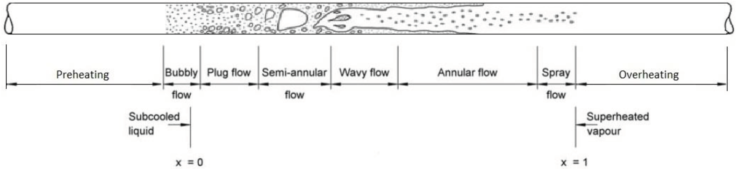
Figure 3.
Main menu SOLEEC software.
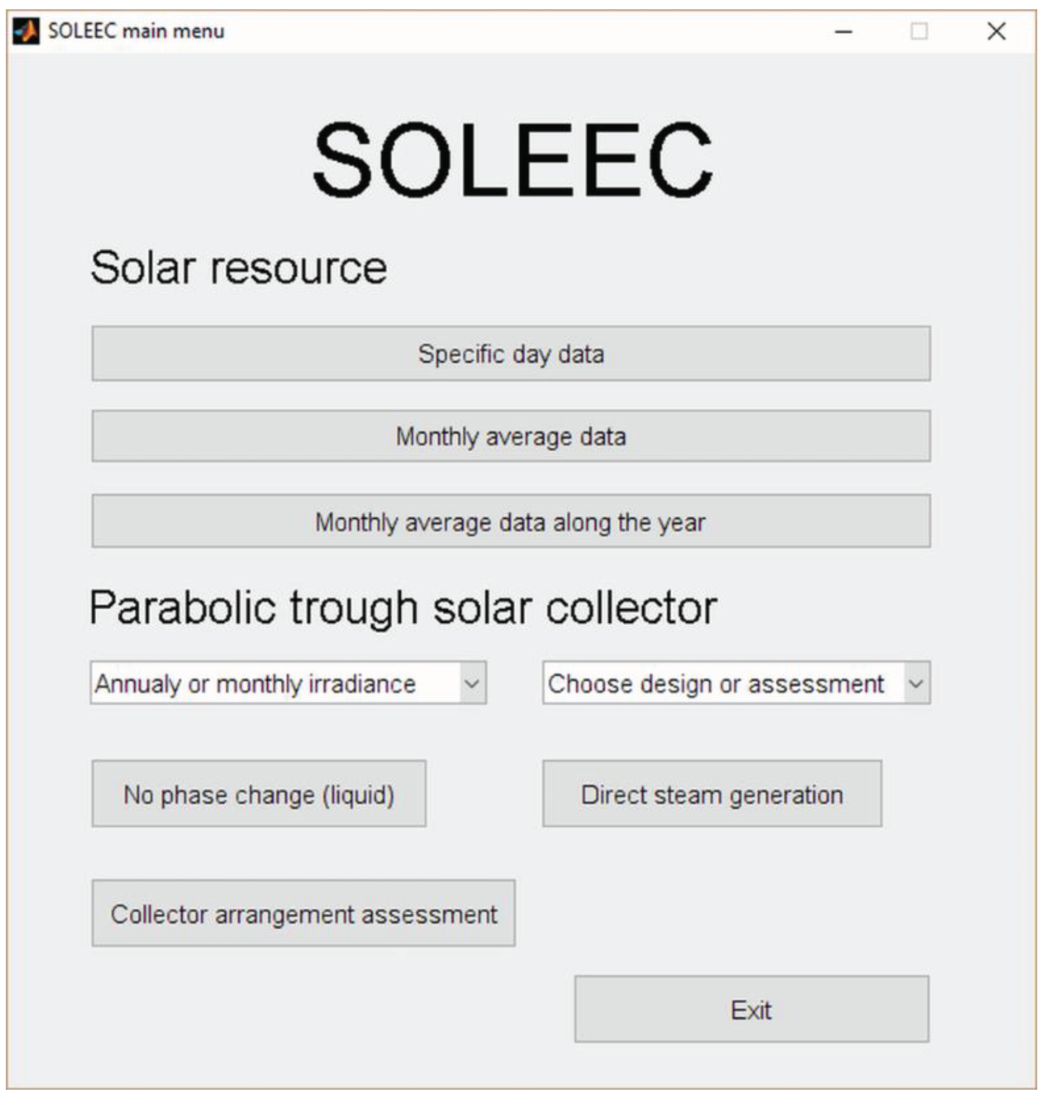
Figure 4.
DSG results from SOLEEC software.
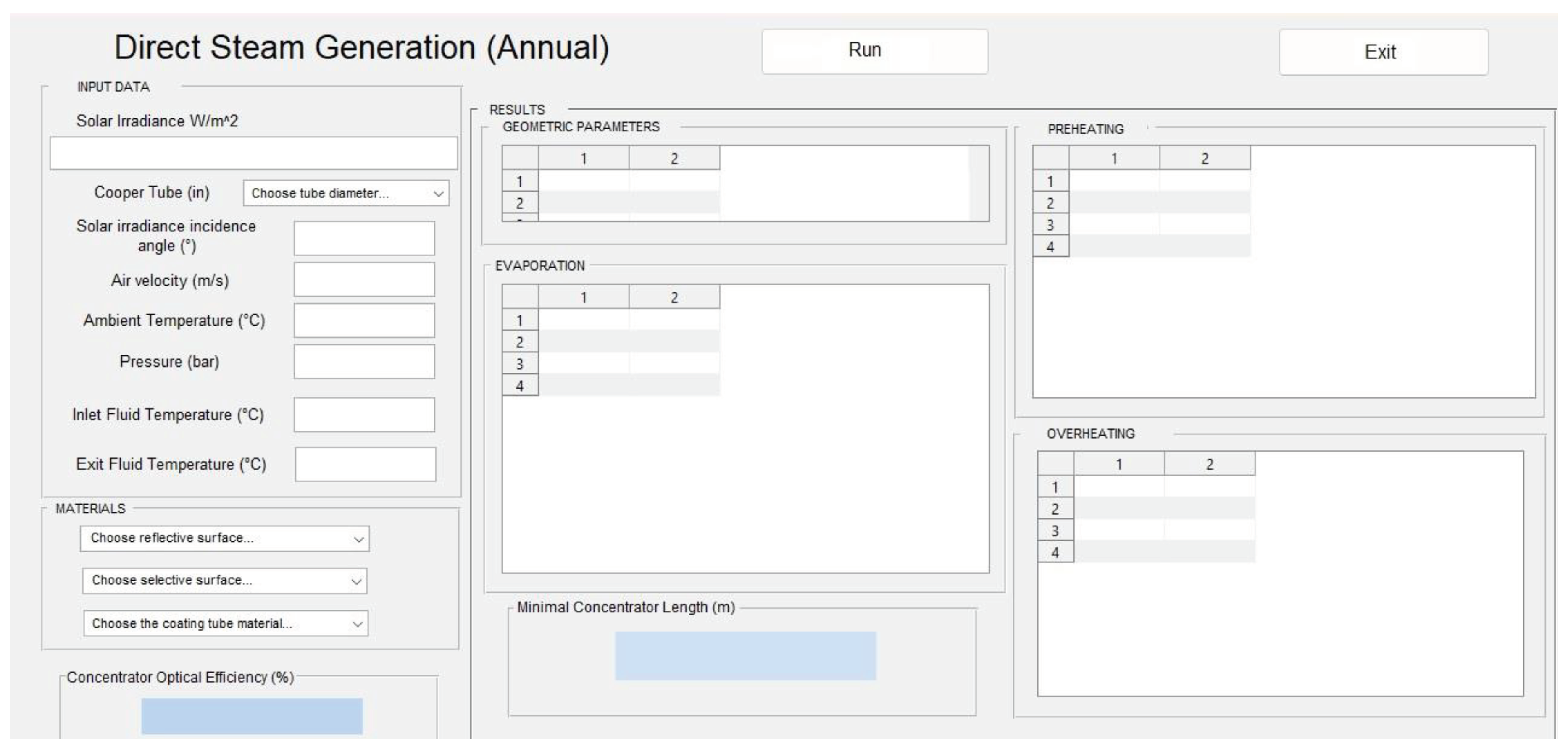
Figure 5.
- Schematic diagram of the Integrated Solar Combined Power Plant, Agua Prieta II [18].
Figure 5.
- Schematic diagram of the Integrated Solar Combined Power Plant, Agua Prieta II [18].
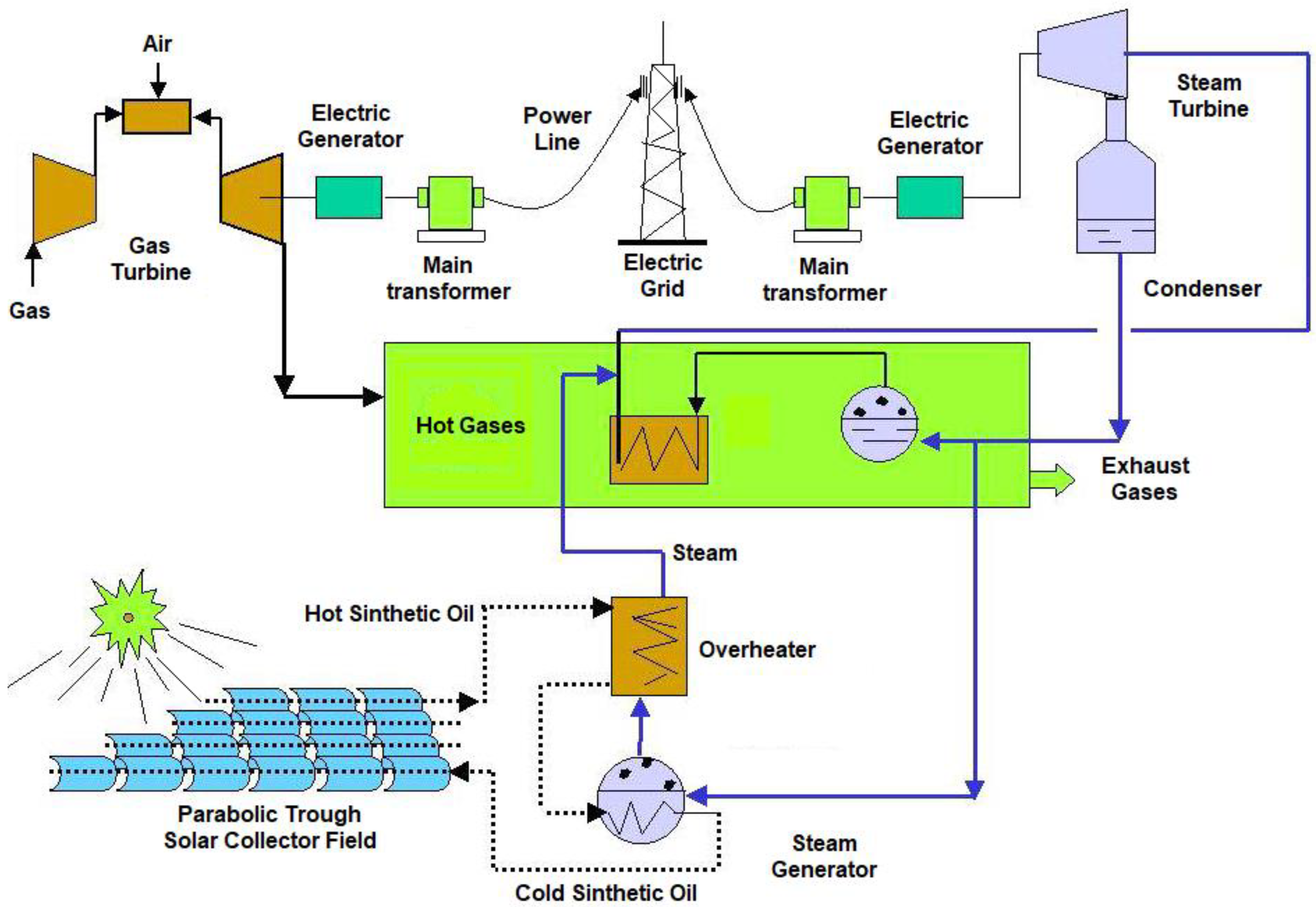

Table 1.
Materials considered in SOLEEC software.
| PTC component | Material |
|---|---|
| Reflective surface | Aluminum anonaized Silver covering Acrylic aluminized |
| Selective surface | Black chrome Lead sulfate paint Copper oxide |
| Absorber pipe | Copper 3/4, 1, 2, 3. 4 (in) nominal diameter |
| Coating tube | Acrylic Borosilicate |
Table 2.
Operation Conditions for the Power Plant Agua Prieta Sonora II.
| Operative conditions | Values |
|---|---|
| Guaranteed steam flow | |
| Working pressure | 130 bar |
| Steam temperature | 330 °C |
Table 3.
Agua Prieta’s solar resource (https://power.larc.nasa.gov/data-access-viewer/).
Table 3.
Agua Prieta’s solar resource (https://power.larc.nasa.gov/data-access-viewer/).
| Month | Solar irradiation |
Solar insolation hours for representative day | |
|---|---|---|---|
| January | 6.87 | 10.2 | 673.53 |
| February | 7.59 | 10.9 | 696.33 |
| March | 8.48 | 11.8 | 718.64 |
| April | 8.62 | 12.76 | 675.55 |
| May | 10.04 | 13.6 | 738.24 |
| June | 8.27 | 13.9 | 594.96 |
| July | 5.40 | 13.8 | 391.30 |
| August | 6.25 | 13.1 | 477.10 |
| September | 6.05 | 12.2 | 495.90 |
| October | 8.44 | 11.2 | 753.57 |
| November | 6.74 | 10.4 | 648.08 |
| December | 5.41 | 10 | 541.00 |
| Annual average | 7.34 | 11.98 | 617.01 |
Table 4.
Geometric parabolic trough collector parameter for every diameter studied.
| Diameter (in) | Aperture (m) |
Focal length (m) | Internal coating tube diameter (m) | Coating tube thickness (m) |
|---|---|---|---|---|
| 1 | 3.0545 | 0.7636 | 0.0666 | 0.0042 |
| 2 | 5.7695 | 1.4424 | 0.095 | 0.005 |
| 3 | 8.4846 | 2.1211 | 0.12 | 0.005 |
Table 5.
Analysis for the 1 inch absorber tube PTC collector.
| Month | Preheating section length (m) |
Evaporation section length (m) | Total length (m) | Steam mass flow (kg/s) | Total heat gained (W) |
|---|---|---|---|---|---|
| January | 8.036 | 6.675 | 14.711 | 0.0083 | 20200 |
| February | 7.960 | 6.612 | 14.572 | 0.0085 | 20700 |
| March | 7.985 | 6.633 | 14.618 | 0.0088 | 21500 |
| April | 8.012 | 6.655 | 14.667 | 0.0083 | 20200 |
| May | 8.038 | 6.677 | 14.715 | 0.0091 | 22200 |
| June | 8.001 | 6.646 | 14.647 | 0.0073 | 17800 |
| July | 7.999 | 6.645 | 14.644 | 0.0048 | 11600 |
| August | 7.927 | 6.585 | 14.512 | 0.0058 | 14100 |
| September | 8.021 | 6.663 | 14.684 | 0.0061 | 14800 |
| October | 8.048 | 6.685 | 14.733 | 0.0093 | 22700 |
| November | 7.949 | 6.603 | 14.552 | 0.0079 | 19200 |
| December | 7.955 | 6.608 | 14.563 | 0.0066 | 16100 |
Table 6.
Analysis for the 2 inches’ absorber tube PTC collector.
| Month | Preheating section length (m) |
Evaporation section length (m) | Total length (m) | Steam mass flow (kg/s) | Total heat gained (W) |
|---|---|---|---|---|---|
| January | 14.864 | 12.347 | 27.211 | 0.0290 | 71000 |
| February | 14.923 | 12.396 | 27.319 | 0.0301 | 73700 |
| March | 14.892 | 12.370 | 27.262 | 0.0310 | 75900 |
| April | 14.871 | 12.353 | 27.224 | 0.0291 | 71300 |
| May | 14.918 | 12.392 | 27.310 | 0.0319 | 78100 |
| June | 14.855 | 12.339 | 27.194 | 0.0256 | 62700 |
| July | 14.645 | 12.165 | 26.810 | 0.0166 | 40600 |
| August | 14.761 | 12.262 | 27.023 | 0.0204 | 49900 |
| September | 14.759 | 12.260 | 27.019 | 0.0212 | 51900 |
| October | 14.935 | 12.406 | 27.341 | 0.0326 | 79800 |
| November | 14.862 | 12.345 | 27.207 | 0.0279 | 68300 |
| December | 14.805 | 12.298 | 27.103 | 0.0232 | 56800 |
Table 7.
Analysis for the 3 inches’ absorber tube PTC collector.
| Month | Preheating section length (m) | Evaporation section length (m) | Total length (m) | Steam mass flow (kg/s) | Total heat gained (W) |
|---|---|---|---|---|---|
| January | 21.819 | 18.124 | 39.943 | 0.0626 | 81800 |
| February | 21.812 | 18.119 | 39.931 | 0.0647 | 84600 |
| March | 21.854 | 18.153 | 40.007 | 0.0669 | 87400 |
| April | 21.788 | 18.099 | 39.887 | 0.0627 | 82000 |
| May | 21.846 | 18.147 | 39.993 | 0.0687 | 89800 |
| June | 21.741 | 18.059 | 39.800 | 0.0551 | 72000 |
| July | 21.358 | 17.741 | 39.099 | 0.0356 | 46500 |
| August | 21.552 | 17.902 | 39.454 | 0.0438 | 57200 |
| September | 21.587 | 17.931 | 39.518 | 0.0456 | 59600 |
| October | 21.869 | 18.166 | 40.035 | 0.0702 | 91800 |
| November | 21.770 | 18.084 | 39.854 | 0.0601 | 78500 |
| December | 21.653 | 17.986 | 39.639 | 0.0499 | 65200 |
Table 8.
PTC necessary collectors and total aperture area for every study case.
|
Absorber tube diameter (inches) |
Mass flow (kg/s) | Number of PTC collectors | Total aperture area (hectares) | |||
| Minimal | Highest | Minimal | Highest | Minimal | Highest | |
| 1 | 0.0048 | 0.0093 | 4290 | 2214 | 19.172 | 9.896 |
| 2 | 0.0166 | 0.0326 | 2140 | 632 | 19.450 | 9.903 |
| 3 | 0.0356 | 0.0702 | 579 | 294 | 19.515 | 9.897 |
Disclaimer/Publisher’s Note: The statements, opinions and data contained in all publications are solely those of the individual author(s) and contributor(s) and not of MDPI and/or the editor(s). MDPI and/or the editor(s) disclaim responsibility for any injury to people or property resulting from any ideas, methods, instructions or products referred to in the content. |
© 2023 by the authors. Licensee MDPI, Basel, Switzerland. This article is an open access article distributed under the terms and conditions of the Creative Commons Attribution (CC BY) license (http://creativecommons.org/licenses/by/4.0/).
Copyright: This open access article is published under a Creative Commons CC BY 4.0 license, which permit the free download, distribution, and reuse, provided that the author and preprint are cited in any reuse.


