Submitted:
19 February 2024
Posted:
21 February 2024
You are already at the latest version
Abstract
The article suggests methods that allow creating the most complicated type of polygonal masonry existing in Peru. This masonry type consists of large stone blocks weighing from several hundred kilograms to several tons fitted close to each other almost without a gap between complicated curved surfaces over a large area. The work provides a description of techniques, which apparently were used by builders who arrived from Europe. The techniques under discussion are based on the use of a reduced clay model, 3D-pantograph, topography translator and replicas. The use of the topography translator, reduced clay model and pantograph provides not only the unique appearance and high quality of the masonry of large blocks, but also allows to increase productivity of the builders significantly. As mechanisms for coping-scaling three-dimensional objects are known since the beginning of the 18th century, the stone structures under consideration should be approximately dated by this time. The remaining simpler types of the polygonal masonry, when the stones are small or the fitted surfaces are almost flat, or the stones contact each other over a small area, or there are significant gaps between the stones, are quite consistent with the well-known methods of stone processing at that or earlier time and, therefore, they do not require any additional explanations. The Fortress Sacsayhuaman is considered as an example of early star fortresses that has survived to our time. The polygonal structures in Peru, the polygonal Face Towers and polygonal bas-reliefs in Cambodia, the symmetrical statues of pharaohs in Egypt are based on the same construction technologies, working methods, tools and technical contrivances. Therefore, with a high probability one can state that all these monuments were created by the same group of architects, sculptors, builders and could not have appeared before the 17th century.
Keywords:
stone block
; polygonal masonry
; clay model
; pantograph
; translator
; parallelogram mechanism
; replica
; chisel
; hammer
; megalith
; star fortress
; Inca
; Cusco
; Ollantaytambo
; Machu Picchu
; Sacsayhuaman
; Peru
; polygonal bas-relief
; polygonal Face Towers
; Angkor
; Cambodia
; symmetrical statue
; pharaoh statue
; Ramses
; Egypt
1. Introduction
Polygonal masonry is a type of masonry made of natural stone. Stones having an initially arbitrary shape are processed in such a way that form irregular polygons tightly adjacent to each other on the front side of the structure. [1] It should be noted that the name “polygonal masonry” is largely conditional. The fact is that there are many structures classified as polygonal in which stone “polygons” have curved sections besides the linear ones. A feature of the polygonal masonry is that it does not require a building mortar (dry masonry). The polygonal masonry possesses sufficient strength and stability to withstand moderate earthquakes [2,3,4,5].
In the present paper, a polygonal masonry in the megalithic structures located on the territory of modern Peru is under consideration. The main attention is paid to the masonry consisting of large stone blocks weighing from several hundred kilograms to several tons fitted close to each other almost without a gap between curved surfaces of large area. The remaining simpler types of the polygonal masonry, when the stones are small [6] or the mating surfaces are almost flat [6,7] or the stones contact each other over a small area [7], or there are significant gaps between the stones, are quite correspond to the long-known methods of the stone processing and, therefore, they do not require any special explanation.
1.1. Design features of the dry polygonal masonry
Since mortar is not used in the polygonal masonry, to ensure integrity of a structure, significant static friction forces should act in addition to the mechanical locking between the stone blocks of the masonry. The static friction force depends on the stone-by-stone static friction coefficient, weight of the stone block and the microrelief in the contact area of the surfaces. Since the friction coefficient is determined mainly by the properties of the used material, it cannot be changed for chosen rock. Although the contact area does not affect the value of the static friction force practically, nevertheless, its increasing (especially between the horizontal faces of the blocks) allows to distribute the block weight more evenly without using mortar that reduces local stresses and thus decreases a probability of wall cracking and stone crushing.
In the long term, a large contact area can provide effective mineralization (filling) of the gap in the contact area with penetrating aqueous mineral solutions (see Section 3.3), which further increases the strength, cohesion, and stability of the masonry. It is known that with equal adherence to all other requirements, the thinner the mortar layer, the stronger the masonry with mortar. [8] Thus, the type of the polygonal masonry under consideration, in which the mineralization (monolithing) of the gap between the stones tightly adjacent to each other takes place, provides maximum strength of the masonry and, in this regard, brings it closer to the theoretical strength limit. The only thing that cannot be reached in such masonry is a good bonding8 of the blocks due to widely varying shape and sizes of the used stone blocks.
Obviously, the larger the vertical size of the stone blocks, the smaller is the number of courses of the polygonal masonry for a given wall height. Moreover, it is known that increasing the height of a stone block increases its bending resistance abruptly (in proportion to powers of two) [8]. As a result, those polygonal masonry turns out to be stronger which stone blocks have a greater height. Thus, to achieve the high strength and stability of the polygonal structure, it is necessary to use as heavy (large size) stone blocks as possible, maximize the contact area between the adjacent blocks, and obtain a certain microrelief in the contact area.
It follows from the foregoing that the concept feature of the polygonal masonry under consideration is the use of large, heavy stone blocks weighing from several hundred kilograms to several tons. The Peruvian polygonal masonry is usually applied for erection of load-bearing walls of the first floor or retaining walls intended for slope strengthening. A dry polygonal masonry of small blocks does not provide adequate strength and stability of the structure. The polygonal masonry of large blocks with large gaps was made by simple transfer of sizes. More advanced polygonal masonry of large blocks tightly contacted with each other over a curved surface of large area required applying new, more complex techniques for block mating (see Section 2.3) as well as invention of special contrivances. The article describes two such possible contrivances – a topography translator (see Section 2.11) and more complex 3D-pantograph [9] (see Section 2.1, Section 2.6, Section 2.7, Section 2.8, Section 2.9, Section 2.10). In addition, the article provides several methods to use these devices, it explains advantages and disadvantages of these methods, and their areas of applicability.
1.2. Construction material used
The main building materials of those years were boulders and blocks of rock of random (arbitrary) shape. As a rule, this building material did not need to be extracted (broken out in quarries), since it was initially presented everywhere in the form of multi-meter deposits of mountain debris formed at the foot of the mountains as a result of fallings and landslides. In most cases, this material did not even need to be transported from anywhere, since construction took place usually at those locations where the stone material was already in great abundance. If a megalithic structure was located on top of a mountain, then the construction material was taken (broken out) here on the site. That is why, for example, the top of the mountain, where the Machu Picchu complex of buildings is located, is cut off, while the tops of the neighboring mountains, where no one lives, are sharp.
At first, the boulders are being examined. The boulder is split along the crack while detecting visible cracks. If the boulder consisted of, say, two parts connected by a comparatively narrow bridge, the boulder was split across this narrow bridge. The boulder surfaces were roughly preprocessed with a sledgehammer to obtain stone billets of a simpler shape. In particular, too prominent sharp corners were removed.
1.3. Comparative analysis of fabrication methods, pros and cons
In general, a polygonal masonry is not something unprecedented, such masonry has been used in Europe since antiquity [5,10]. In the Peruvian version, only the quality of the curved interfaces is striking, which is not easy to repeat even in our time [11]. The methods suggested by both the scientific-engineering community [6,11,12,13,14,15,16] and enthusiasts [17,18,19,20,21] for fabrication of the Peruvian polygonal masonry do not explain all the observed features and/or are often far from a reality.
The methods of polygonal masonry fabrication proposed by the author are based on the use of a reduced clay model and 3D-pantograph [9] (see Section 2.1, Section 2.6, Section 2.7, Section 2.8, Section 2.9, Section 2.10), topography translator (see Section 2.11), and replicas [12] (see Section 2.3 and Section 2.6). A distinctive feature of the polygonal masonry type under consideration and the methods of its creation is that a drawing with indicated there dimensions and tolerances is not required for precise fabrication of complex shaped stone blocks. When creating a wall by the method of polygonal masonry, only wall thickness and height are held by selecting stone billets of appropriate sizes, and even then approximately. These features significantly speed up and simplify the process of creating structures based on polygonal masonry from stone blocks of arbitrary shape.
The main tools for stone processing in the suggested methods are a hammer and steel chisel (in practice, a set of chisels of different types [22] made of hardened steel). Besides the hammer and chisel, to work effectively with stone blocks, another simple tool is needed that many often forget about, this is a steel crowbar. The use of the topography translator, reduced clay model and pantograph provides not only the well-known unique appearance and high quality of masonry of large blocks, but also allows to significantly increase the productivity of the builders. Only due to the high productivity it became possible to carry out the volumes of the polygonal construction revealed in Peru for an acceptable time, engaging a reasonable amount of labor force.
If we closely look at the shape of the stones in the masonry, at the sites of their almost perfect fitting, then there is a feeling that the stones were not processed mechanically but were sculpted (see Section 3.1). In this regard, many researchers mistakenly decided that the stones were sculpted or cast from a certain plastic mixture – artificial granite, concrete, geopolymeric concrete, lime, rock softened by heating, and so on [18,19,20,21]. In this regard, the question immediately arises: why produce an expensive plastic mixture when there is a lot of ready-to-use material around – natural stone of arbitrary shape? What is even more unclear is: why should plastic mixture be given such complex shapes? Why not make a limited range of standard concrete blocks with locking elements, for example? Nevertheless, a sculpting really took place during the polygonal construction, but it was the sculpting of a reduced model of the future stone block from clay, not the sculpting of the stone block itself. Further, using a 3D-pantograph, the “sculpture” was simply transferred to a stone block with the enlargement set in the pantograph by means of a hammer and chisel.
There are other arguments against the plastic version. For example, the backside of many blocks is a ragged stone; there is no plastic mixture flowed into the interblock spaces inside the masonry; the stone blocks have veinlets and other features inherent in natural stone. [23] Unlike clay, concrete [18], lime, and artificial granite are not suitable for hand modeling. Therefore, the blocks cast from these materials will have flat interface surfaces, as well as flat front and back sides, determined by the flat panels of the formwork used. Thus, if, for example, smooth L- or U-shaped recesses are present in the masonry, then, most likely, this masonry was not fabricated by the casting method generally accepted in construction (see also Section 2.2).
Any products obtained by casting/sculpting [21] shrink during the drying process. The shrinkage of modern concrete can reach 3%, lime shrinkage is noticeably greater. The casting shrinkage leads to casting size decrease, warping (shape distortion) and to cracking, as a result. Thus, the presence of cracks can be one of the casting hallmarks. The shrinkage-induced casting size decrease, in turn, leads to interblock gaps. Since the initial shape of the blocks in the polygonal masonry is irregular, the shrinkage in addition turns out to be non-uniform. Accordingly, the gaps resulting from such shrinkage will be non-uniform too (nonparallel, see [19]).
Thus, even if the blocks are cast sequentially one after another “in-place” [18,19], waiting each time for the end of the shrinkage (ideal case), it is still not possible to completely eliminate gaps between the blocks. For the reinforcement-free concrete block with modest sizes of 50×50 cm (width × height) having typical average shrinkage coefficient of modern concrete of 1.5%, the gap between the blocks makes 7.5 mm (!). The larger are the sizes of the blocks, the greater is the value of their shrinkage, and, accordingly, the larger is the resulting gap.
The shrinkage can be reduced by using steel reinforcement and/or adding crushed stones of hard rock to the concrete mix. To hide the use of the crushed stones, the front side of the blocks should be covered with a plaster layer. Surely, there are also quite expensive shrinkage-free concretes (shrinkage coefficient 0.1%), but this invention is relatively recent. Thus, additional signs of the concrete technologies will be: reinforcement, crushed stone inclusions, a layer of plaster. When, according to a number of signs, we see that some blocks of a polygonal masonry are made by casting/sculpting of a concrete-like material, that, unfortunately, takes place in many known Peruvian monuments, before us are either a fake of recent times or unsuccessful repair/restoration. [24]
Figure 1 shows an approximate view of the cast polygonal masonry of blocks tightly-abutted to each other. First, the large blocks are cast. After shrinkage termination, the polygonal masonry is assembled from the large blocks sequentially block by block (numbers in the figure show block installation order). After installing each course of the large blocks, small (compensatory) spaces between the large blocks are filled with concrete. Before casting, a thin layer of material is coated on the hardened concrete to prevent adhesion of the fresh concrete with the hardened one [18,19]. If necessary, the installation of large blocks resting on a still missing compensation insert is carried out using small temporally installed wedging stones. Note that the polygonal masonry obtained according to the described technology may not be completely dismountable in some cases.
It is seen from the presented procedure that the interface surfaces in the polygonal masonry obtained by the casting should be close to planes and the masonry itself should have a rather specific appearance (see Figure 1). The large non-marginal blocks in such masonry are in a conditional contact with the neighboring large blocks with only two of their sides – the base and top face; the contacts of the rest (lateral) sides occur through the small blocks with a small shrinkage of their own. The small blocks are designed to compensate for the shrinkage-related size reductions and shape changes of the large blocks. Only this approach allows to reduce to a minimum (but not to zero) the gaps between the concrete blocks obtained by casting.
The disadvantage of the presented masonry is a rather weak bonding of the blocks. The insufficiently good bonding of the blocks results in separation of the masonry into loosely connected “posts” [8]. In Figure 1, such posts are formed by the blocks 1-8-9-18, 2-7-10-17, 3-6-11-16, and 4-5-12-13-14-15. Moreover, local posts (blocks 12-15 and 13-14) may form within the posts. All this affects the strength and stability of the proposed type of the polygonal masonry negatively.
The more sides a large concrete block has, the more the compensating inserts are required, accordingly, the more complex the formwork used is. Since there are no triangular blocks in the Peruvian polygonal masonry, the simplest shape of the block in this case is a conditional quadrilateral (more precisely, a conditional parallelepiped). The conditional quadrilateral occurs if one ignores changes in the shape of a large polygonal block related to the recesses for the compensation blocks in its body.
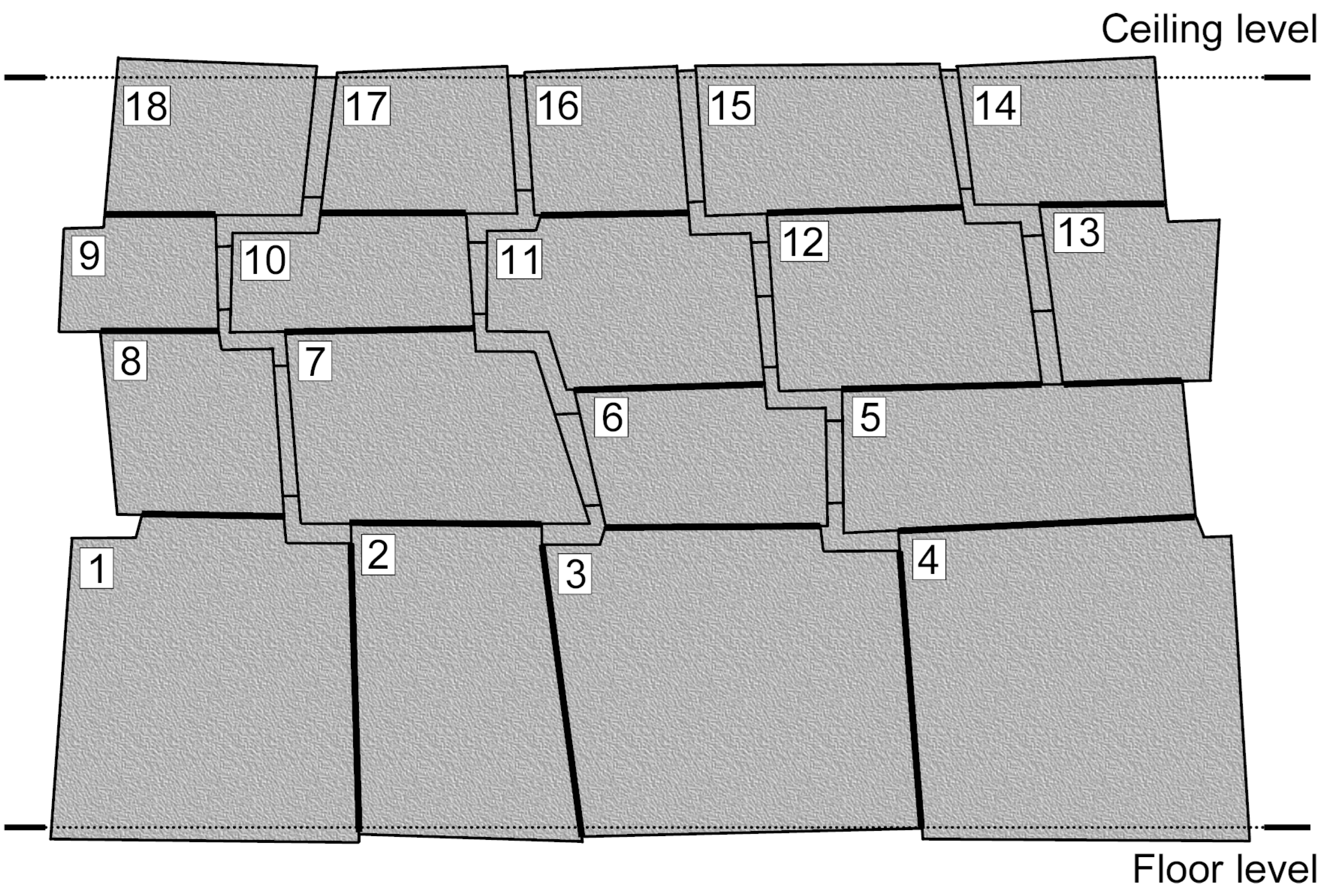
Figure 1.
The probable appearance of a casted polygonal masonry of blocks tightly-abutted to each other. The small blocks casted at the final stage are intended for taking up the interblock gaps caused by a concrete shrinkage in the large blocks. The abutment sections between the large blocks (shown with a bold line) are only depicted as rectilinear with zero gaps, in reality, these sections, strictly speaking, are curvilinear and the abutments always have an irregular gap due to the uneven shrinkage. The larger is the shrinkage coefficient and the larger is the block sizes, the wider are the gaps. Block deviations from the floor and ceiling levels due to a shrinkage are exaggerated for more clarity. The disadvantage of the masonry is a rather weak bonding of the blocks. The numbers show the installation order of the large blocks.
Photo 1 shows a section of stone polygonal masonry with narrow vertical inserts [25] at the corner of Maruri and Qapchikijllu streets in Cusco. It could be assumed that this masonry was fabricated by the casting method discussed above. However, unlike the masonry shown in Figure 1, the presented section is the only one and no longer repeats along the wall. On the other hand, if the stone blocks of this masonry were fabricated mechanically, the masonry would not have the narrow vertical inserts. In case of a mechanical processing, the lateral sides of the stone blocks would simply abutted directly to each other. With that, it would only be necessary to ensure the proper block bonding. In the case of a mechanical processing, the masonry shown in Photo 1 can only contain quadrangular inserts contacting their four sides with four adjacent blocks. However, the masonry style of the rest part of the wall is completely different – the blocks having shape close to parallelepiped are laid in courses, each course consists of the blocks of approximately the same height.
Nevertheless, the mating of the stone blocks shown in Photo 1 can occur while processing mechanically if a wall construction is carried out from both directions towards each other using standard-sized blocks. In this case, a small gap may form at the meeting site. Typically, the masonry of identical blocks is started from a corner and closed with the similar narrow inserts, if necessary, somewhere on the backside or a lateral side of the building in an inconspicuous place. However, the masonry section in question consists of unequal length blocks and is located on the corner of the building, moreover, on its facade side. Besides that, the narrow horizontal inserts (leftmost) cannot be justified either by a casting or mechanical treatment. It follows from the conducted analysis that the quadrangular inserts, the narrow vertical and horizontal inserts, most likely, had to be embedded in this masonry site during some repair related to elimination of a crack, chippings/crumbling of the blocks. The presence of a thick layer of mortar confirms this assumption additionally.
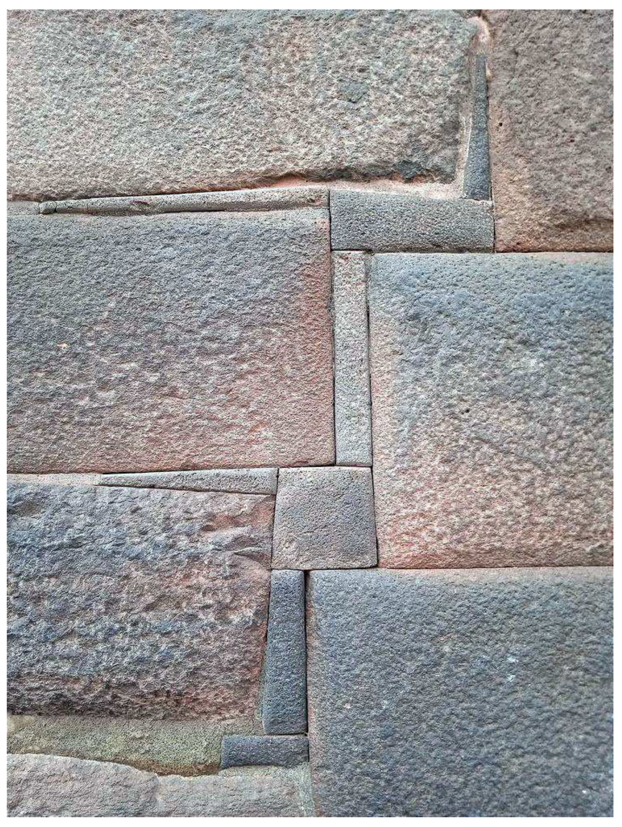
Photo 1.
A section of the polygonal masonry with narrow vertical and horizontal inserts. Cusco (author of the photo is unknown, 2022).
Photo 1.
A section of the polygonal masonry with narrow vertical and horizontal inserts. Cusco (author of the photo is unknown, 2022).
Initially, in the design presented in Figure 1, quadrangular inserts like those in Photo 1 were used, which four sides contact with the four adjacent blocks. However, these quadrangular inserts were replaced by L- and Z-shaped inserts later on ensuring greater strength and stability for the building but making it incompletely collapsible. Since no masonry similar to the one shown in Figure 1 has been found in Peru, the methods of casting into a formwork were not used for fabrication of the polygonal walls from the blocks tightly-abutted to each other.
In the article, besides the mechanical treatment of stones by means of a hammer and steel chisel, the method is also proposed that allows casting large polygonal blocks into a mold (see Section 2.2). In this case, the tight abutment of polygonal masonry blocks is achieved due to high casting accuracy (small shrinkage). According to this technology, the typical signs of the casting are: a solid/hollow core made of cheap concrete-like material and a comparatively thin shell made of more expensive artificial granite.
As for influence of a chemical [16] or heat [26] treatment on a natural stone, it results in the nonuniform surface layer formation with degraded mechanical properties. A polygonal masonry assembled of such stone blocks will disintegrate soon because of crumbling of the stone blocks at their contact points.
1.4. Historical, economic, political, civilizational and other aspects
By the time the Europeans conquered the South America, the Indians did not know either iron tools or a wheel or a potter’s wheel, did not have draft animals, did not own the technology of brick firing, and did not possess a written language. Peru is a mountainous country, thus, it is impossible to grow large volumes of agricultural products there simply because of an acute shortage of sown areas suitable for agriculture. The acute shortage of agricultural land, in fact, became the reason for the large-scale construction of the terraces [27] on the mountain slopes, especially at that moment of the Peruvian history, when the arrived Europeans have launched the large-scale mining of gold and silver. A town (civilization), let alone an empire, cannot arise without a developed agriculture. The developed agriculture implies the food production in commodity quantities.
On himself, a peasant is able to plow a vegetable garden from which only his family will feed. To feed several families of townspeople, the peasant needs to use agricultural machines of those years – horses or oxen, as well as agricultural implements to those “machines”. In order to deliver food and raw materials for craftsmen in the town, transport machines of those years – carts and wagons drawn by horses or oxen, at least mules and roads were required. Agricultural and transport machines of those years – horses need “fuel” to work, a lot of fuel. Therefore, a part of the scarce land will have to be taken away for grazing and for fodder grain cultivation.
Since the towns in Peru could not self-originate for the above reasons, then an empire could not arise in Peru. The Inca Empire is a fiction, a myth, it never existed (see Section 3.5). In certain natural and climatic conditions, human settlements in the form of a village can exist indefinitely. The first towns in Peru appeared only when European settlers arrived there. The settlers brought the iron tools, wheeled transportation, horses, cereal crops, modern for that time weapons, agriculture and handicraft technologies, written language; established own laws, introduced money and commodity-money relations, built the roads and bridges; had ordered the religious beliefs of the Indians gradually; being the victors, they composed a nice history of Peru to form the nation state [28,29].
Taking into account the above arguments, one can conclude that only the builders who came from Europe could erect the polygonal structures under consideration in the article (see Section 3.5 and Section 3.6). Unlike the Indians, these builders had all the necessary tools, mechanisms, and skills for the large-scale construction. The marks of this large-scale stone construction are visible everywhere – Catholic cathedrals, monasteries, palaces, villas, a lot of urban and industrial buildings, bridges, roads. [30] In particular, the famous Fortress Sacsayhuaman is an example of early star fortresses that survived to our time (see Section 3.6).
Any large-scale construction always implies the existence of an economy corresponding to this scale. Therefore, the article additionally explains what the economy of Peru was based on in those years (see Section 3.5). As machines coping-scaling three-dimensional objects are known since the beginning of the 18th century (see Section 3.4), the polygonal structures under consideration should be dated around this time.
Section 3.8 shows that some “Ancient” Egyptian statues of pharaohs could be made using the casting technology described in Section 2.2. Also, Section 3.8 explains how, by performing a slight modification of the 3D-pantograph design, it is possible to fabricate the “Ancient” Egyptian statues of pharaohs, which left and right halves have a high enough degree of mirror symmetry.
2. Tools, contrivances and methods of fabrication of the polygonal masonry
2.1. Clay model shape transfer on a stone billet by means of a 3D-pantograph
According to the proposed method, first, as consistent with a sketch, the clay model of a structure is made in a reduced scale which blocks form a polygonal masonry. Let us assume for certainty that the structure is just a wall of one block thickness. Small polygonal blocks of the planned shape are sculpted from clay. The sizes of these blocks correspond to the sizes, say, of a basketball or so. The surface interfaces are additionally formed by pressing the blocks into each other. If the project provides for beveled edges, then they are fabricated along edges of the front sides of the model blocks. To reduce shrinkage, a solid core of suitable shape and size – a stone or a piece of dry clay from a previously used model block is put inside the clay blocks.
The model of the wall is assembled from the raw model blocks. During the assembly, some material is laid between the blocks that prevents the blocks from sticking to each other during the drying-solidification process. To reduce the influence of the shrinkage effect, the bottom course is dried first, then the next course, and so on. If necessary, the wall is given the required slope (see Section 2.6). During the drying-shrinkage process, the model blocks are matched more closely under their own weight and with small corrections of the builder. If a shrinkage-resulted gap appears between the model blocks, it is eliminated by putting clay layers of a necessary thickness.
After model wall solidification, it is disassembled. Now “magic” began. The Medieval European builders transferred the surface topography from a small model clay block to a large stone billet of suitable sizes and shape with a specified scale using a 3D-pantograph [9], a hammer, and a steel chisel.
The pantograph is a simple hinge-lever device based on a parallelogram mechanism. [31] A 2D-pantograph allows to proportionally enlarge/reduce a flat drawing [31,32]. Being a logical advancement of the 2D-pantograph, a more complicated 3D-pantograph [33,34] (see Figure 2) allows to proportionally enlarge/reduce a space figure, for example, a statue. In our case, using the 3D-pantograph, the enlarged copy of a small clay model of the block is obtained by processing the stone billet with a hammer and chisel.
The parallelogram mechanism is located on a boom of the 3D-pantograph. Due to cylindrical hinges, the parallelogram mechanism can freely rotate around the boom. The boom is attached to a frame using a ball joint (Pivot in Figure 2). The boom has a counterweight. A sharp probe (Pointer A in Figure 2) is fixed on one arm of the parallelogram mechanism, a sharp pointer (a part actually similar to the probe; Pointer B in Figure 2) – on the other arm. If one touches the clay model with the probe, the pointer will show where the corresponding point of the enlarged copy is located in the space. The enlargement coefficient is set by the appropriate adjustment of the arms of the lever system. The model and its enlarged copy are located each on their rotary platform (Table A and Table B, respectively) backside down. Due to a chain transmission, the platforms can be synchronously rotated around their vertical axes, putting different sides of the model/copy under the probe/pointer.
A minimum size of the model clay block depends on the size of the stone block under fabrication and is determined by the error of the pantograph mechanism ultimately. The size of the model block is also determined by how convenient it is for one or two workers to handle (sculpt, correct, carry, install, shift, turn, etc.) such a block. The modern 3D-pantographs used by sculptors [33,34] (see Figure 2) allow enlargement of the object model by up to 6 times. Thus, by a clay block model size, say, 50×50×50 cm, which can be made hollow to reduce its weight and shrinkage, the stone blocks up to 3×3×3 m can be processed on the not very large pantograph.
It should be noted that by installing a stone billet on the pantograph, the clay model of the block suitable for this billet can be quickly selected. This feature is extremely useful exactly in the case of the polygonal type of masonry, since in such masonry, initial stone blocks often have a complicated shape that requires a lot of preliminary measurements while selecting a billet.
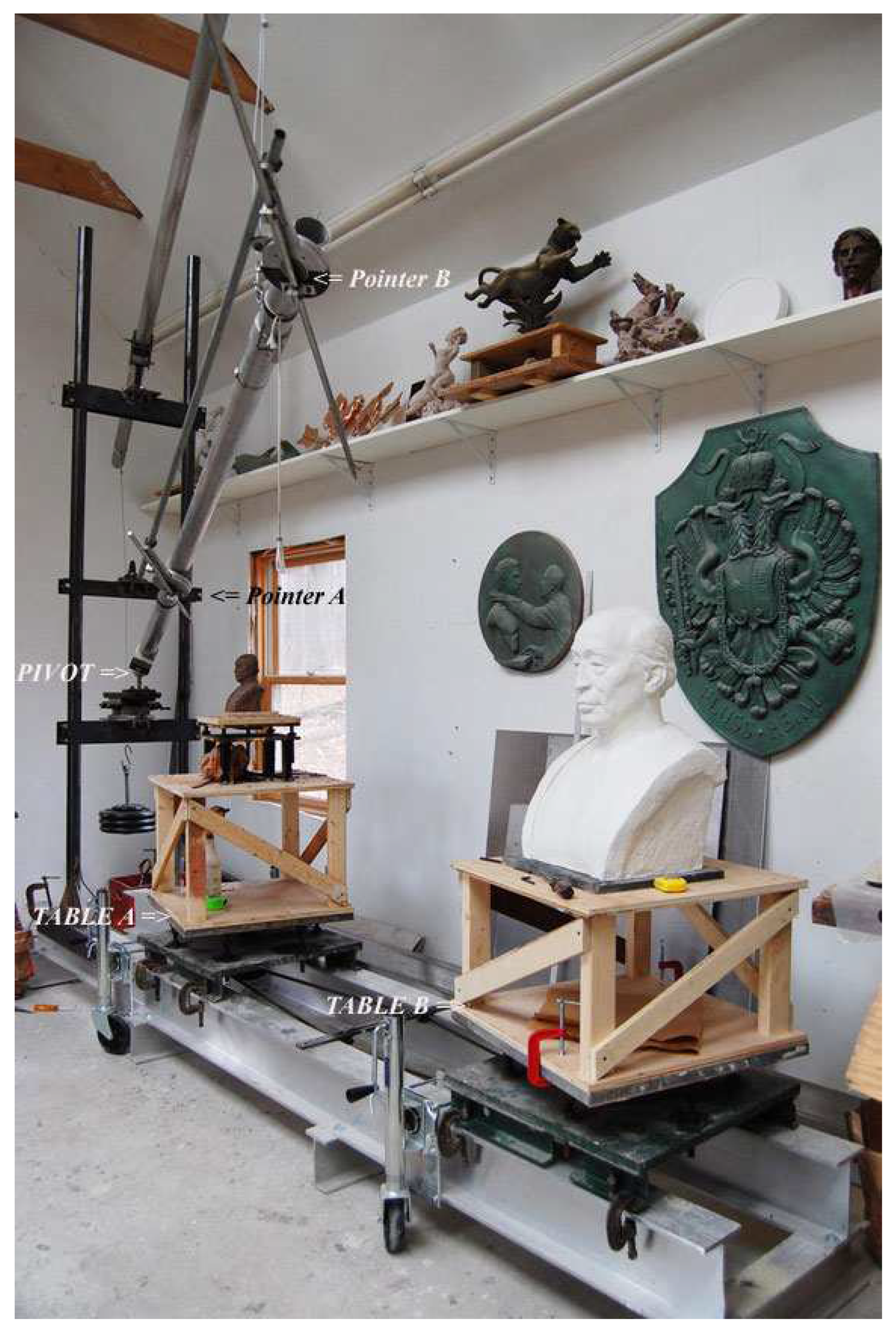
Figure 2.
Modern 3D-pantograph used by sculptors (M. Keropian, www.keropiansculpture.com). The 3D-pantograph allows to proportionally enlarge or reduce a space figure. The pantograph has a frame on which two rotary platforms are located. A model is installed on one platform (Table A), and an enlarged copy of the model is located on the other platform (Table B). A boom is attached to the frame using a ball joint (Pivot). The boom is equipped with a counterweight. There are cylindrical hinges on the boom, to which the parallelogram mechanism is attached. A sharp probe (Pointer A) is fixed on one arm of the parallelogram mechanism, a sharp pointer (Pointer B) – on the other arm. Due to a chain transmission, the platforms can be synchronously rotated around their vertical axes, putting different sides of the model/copy under the probe/pointer. If one touches the model with the probe, the pointer will show where the corresponding point of the enlarged copy is located in the space.
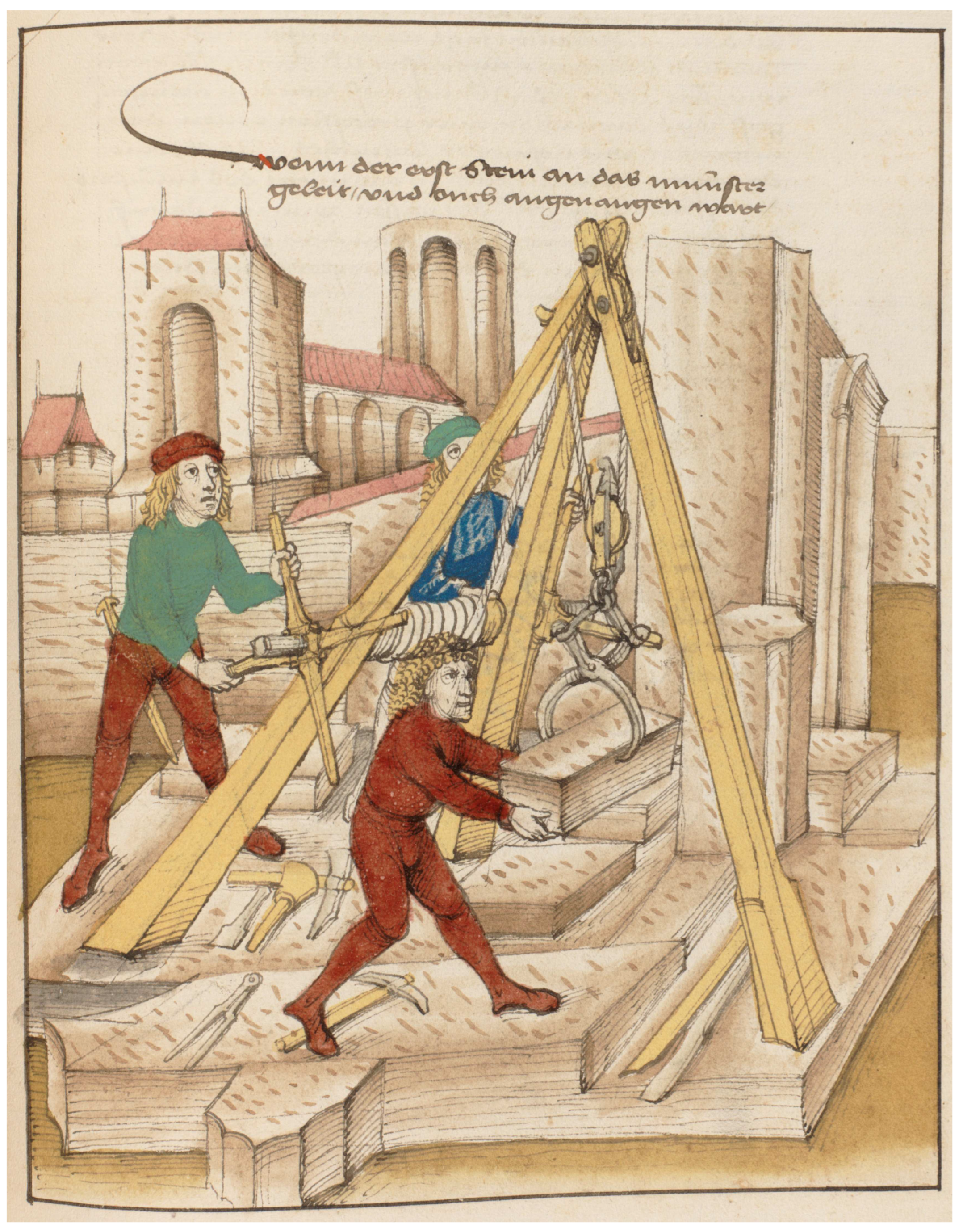
After the mentioned copying process with the specified scale, the wall of stone blocks is assembled without any adjustments using sleds, rollers, levers, steel crowbars, pulleys, [35] blocks and tackles, [36] winches, [37] and cranes [38] of the time [14,15,39,40,41,42]. As an example, Ill 1 shows a picture from the 15th century manuscript, [43] where medieval builders lift stone blocks using a tripod equipped with blocks and tackles and with a winch. With the help of this tripod, it is possible not only to lift a stone block but also to move (drag) the block in the horizontal plane. To do this, alternately, the stone block is lowered on the ground, the tripod is moved by a short distance, and the stone block is slightly raised above the ground again.
Ill 1.
Medieval builders use a tripod with blocks and tackles and with a winch to lift stone blocks. The picture is from a 15th century manuscript. To hold the stone block, a block tongs are used. With the help of the tripod, it is possible not only to lift a stone block but also to move (drag) it in the horizontal plane.
If there is a beveled edge, it is transferred from the clay model to the stone billet during pantographic copying. The front side of a stone block can be copied from the front side of its clay model, but it can be dressed or refined after the polygonal structure assembly. Processing of the backsides of the stone blocks is carried out after assembling a bearing wall. The backside of a retaining wall is not processed in any way. Blocks forming an outer wall corner should be placed with the most lengthy front face down on the pantograph to provide access to the side faces being processed. In such stone blocks, the front face, inaccessible for processing during copying, is dressed after the final assembly of the corner section of the wall.
When a polygonal masonry is built on a leveled reinforced ground, the first course is formed of not large stone blocks having a flat base, which are processed by the corresponding clay models. The stone blocks of the second course are usually noticeably larger than the blocks of the first course (see Photos 2–6, for example). Why is that? Why are the large blocks of the second course not put on the equally large or even larger blocks? There should be good reasons for such a masonry arrangement. Indeed, the higher a large heavy block is located, the higher is its gravity center, the less stable is the wall. Moreover, the load bearing capacity of small stones is less than that of large ones.
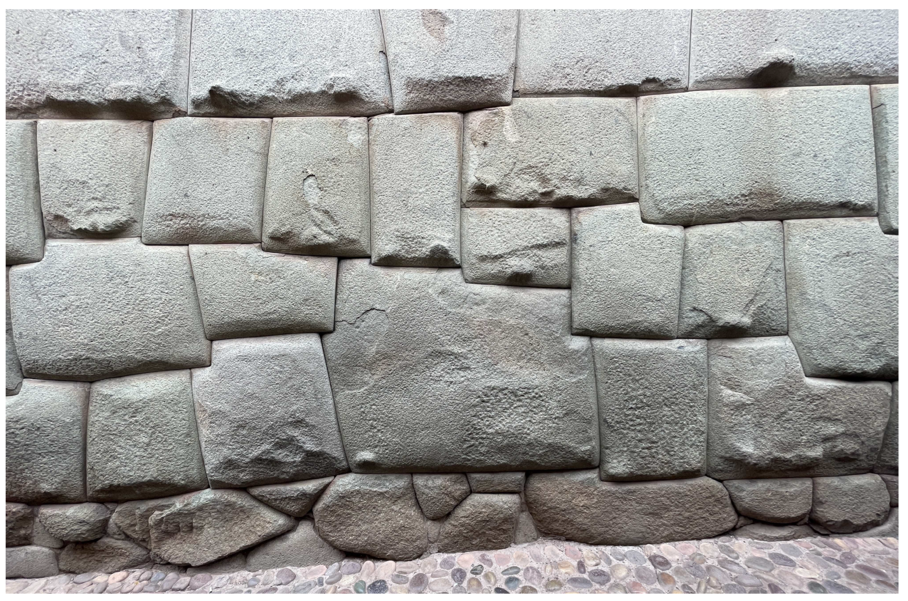
Photo 2.
Cusco (V. M. Soroka, 2021).
As an example, let us consider the wall on the Hatunrumiyoc street [44] in Cusco (see Photos 2–6). Since the street has a slope, one might think that the small stones in the base of the large blocks of the wall are needed to account for this slope. However, there are sections of the polygonal masonry in this wall, where one course of stones splits into two or two courses merge into one. For example, in Photo 2, moving from left to right, the second and the third courses merge into single course – the second course; and the fourth course splits into two courses – the third and the fourth. Thus, we see that the street slope could always be taken into account using the technique of masonry course merging/splitting.
In fact, everything is quite simple. By using the not large blocks of the first course, it is possible to take up the side gaps between the large stone blocks of the second course completely, i.e., correctly locate the latter relative to each other. Only provided that the relative position of the large blocks of the second course is correct, the rest blocks located above can be installed with minimal gaps.
Now, even if the ground would subside under one of the not large blocks of the first course, the neighbor not large blocks of the first course will continue to hold the located above large block of the second course in a predetermined spatial position. Only pressure acting on these blocks will increase. However, this is not a problem since the margin of compressive strength in any stone material is much greater than the margin of bending strength [8]. Thus, the gap caused by the ground subsidence will increase over a small area under the large block of the second course only. The occurring bending force in the large block of the second course is far from a critical value provided that the height of the block is sufficient [8]. Having the large block with sufficient height, the gap occurring under the block does not result in increasing the side gap and gap above the block because of no bending.
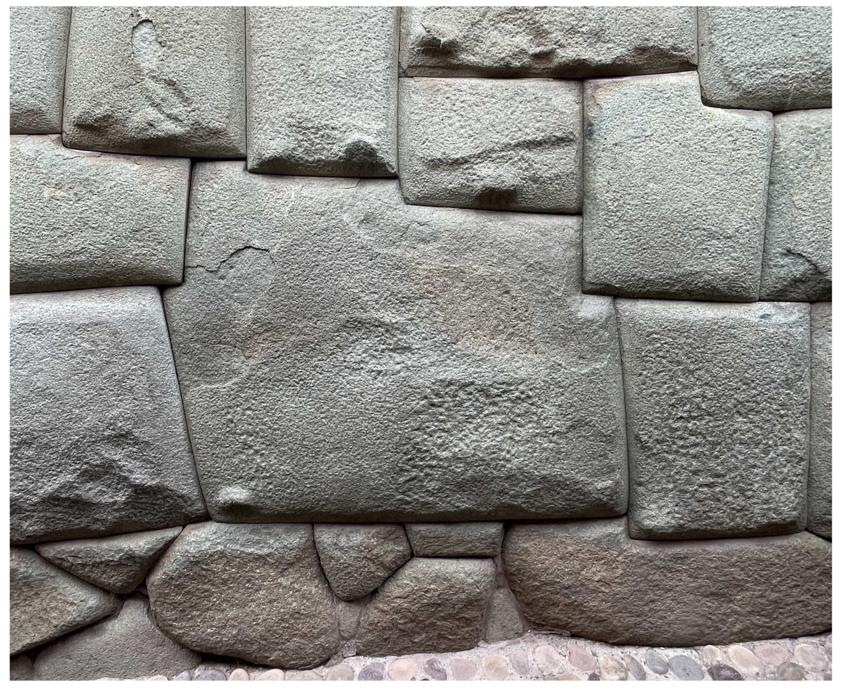
Photo 3.
Cusco (V. M. Soroka, 2021).
If a single extended block is put in the first course instead of the several not large blocks, then a bending (extension) force will inevitably occur in such a block, when the ground subsided under it, and the gap increase will take place over the entire length of the block, and unequally. In some cases, such a block can act as a turning out lever. The occurrence of the unequal gap will cause the spread of unequal gaps higher up in the masonry. As a result, the uneven weight distribution of the stone blocks will occur in this section of the polygonal masonry, which, in turn, would cause formation of a network of bend and shear stresses and, as a consequence, higher probability of cracks and stone crumbling in the wall.
The use of the not large stone blocks in the first course is one more confirmation that the wall of the polygonal blocks of the type under consideration was not built course after course with fitting the stones in-place (see Section 2.11) [13], but it was fabricated by a reduced clay model and then it was only assembled. During the course-after-course construction, the first course of the masonry would always consist of the largest stone blocks, since according to this approach, both the mounting surface for the next stone block and this stone block itself are successively made in-place.
Note that it is difficult to process not large stones in the first masonry course with a hammer and chisel while precise fitting since it is not easy to ensure the stone immobility due to its low weight. A micro-displacement of the stone occurs each time when the hammer strikes by the chisel. Therefore, it is possible that the not large stone blocks in the first masonry course could initially represent a single extended block of small height, which was split into several parts after interface copying with the pantograph. The locations, where the block was divided into parts, were chosen so that the bonding [8,45] of the masonry blocks would not deteriorate.
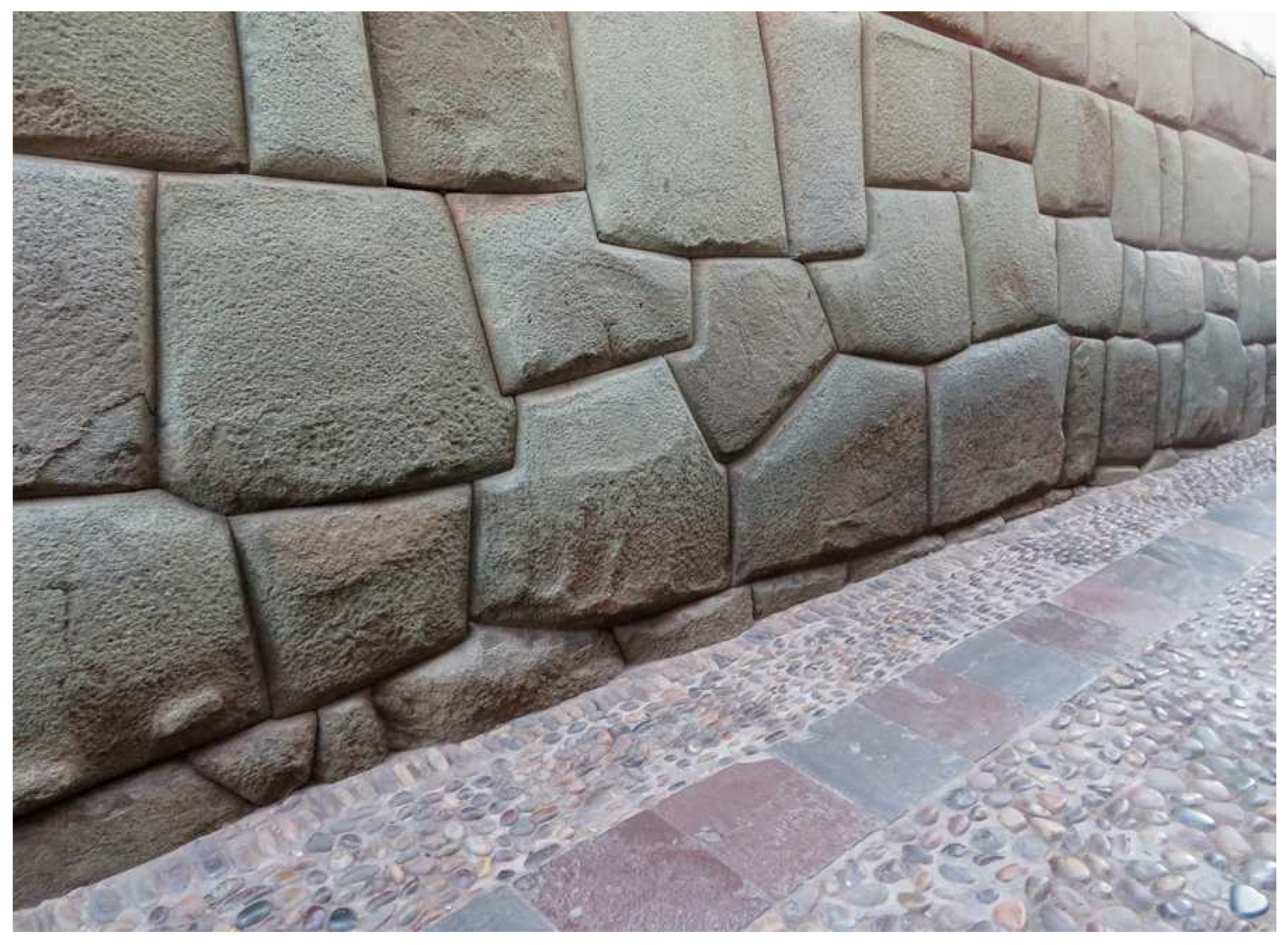
Photo 4.
Cusco (S. N. Kozintsev, photo.sirano.info).
If the base of the not large stone blocks of the first course stands out of the general aesthetics of a particular polygonal masonry, then it can be hidden by a layer of soil (see Photo 11). The soil under the masonry weight will be compacted and the not large stones-wedges of the first course can crack and crumble, then the masonry will slide apart. To prevent such event, hard wedging stones having no visible defects should be used and not in one but in several places; the soil under the building should be strengthened [13]; after laying the first two courses, the work on this site should be stopped and the masonry should be observed for some time, etc.
When a polygonal masonry is erected on a bedrock, the bedrock is pre-prepared. For example, L- or U-shaped recesses are fabricated in the bedrock. Next, clay replicas are taken by the pre-prepared section of the rock. To further correctly locate the model blocks of the first course relative to each other, marks are put with a narrow object on the front and back sides of the clay replicas along a horizontally stretched construction cord. After drying, the replicas are removed from the bedrock and put in the pantograph in place of a stone billet (Table B in Figure 2). Using the pantograph, the surface of the interface with the bedrock and the marks are transferred from the clay replicas on the reduced clay model blocks of the first course. The obtained reduced model blocks of the first course are dried.
To avoid bottom surface damage of the model blocks of the first course, the model blocks are put in beds with a flat base by pressing into raw clay bars. The correct mutual positions of the model blocks of the first course at the construction site of the model wall are adjusted by the above marks by adding soil and installing small wedging stones under the beds of these blocks.
As a rule, the polygonal structures in Peru have no sections that differ by weight significantly. In cases when one part of a polygonal structure rests on a bedrock, and the other part rests on an ordinary, albeit reinforced, ground, unacceptable stresses may occur in the polygonal structure. These stresses originate from the settling of the building part erected on the ground. Due to differences in the foundations of the different parts of the structure, the similar stresses caused by different thermal expansion [46] of the foundations may also occur. In the above cases, a settlement/expansion joint [8,45] should be provided in the polygonal structure. The settlement/expansion joint stretches from the base of the masonry to its top point. The joint provides vertical slipping of the stone blocks of the structure part located on the ground, relative to its other more stable part rested on the bedrock.
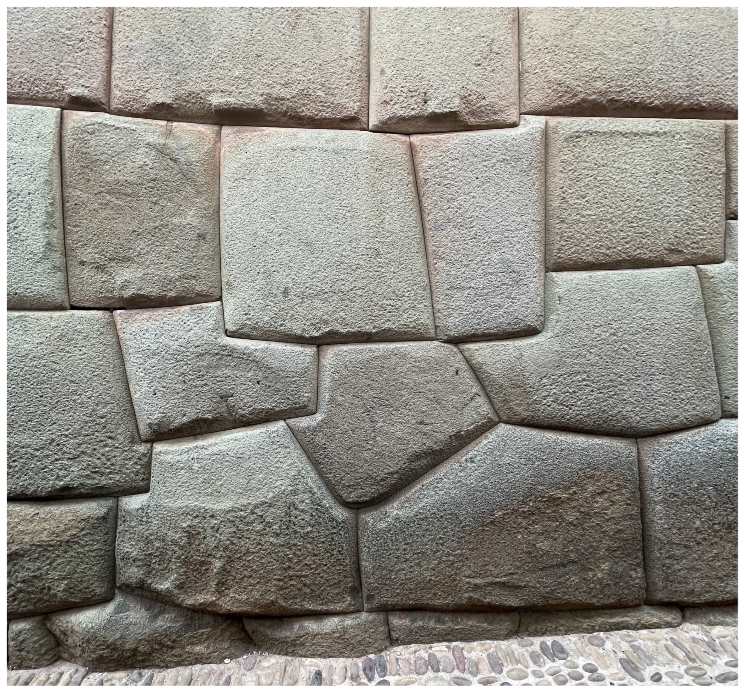
Photo 5.
Cusco (V. M. Soroka, 2021).
The proposed method of geometry transfer from a small clay model to a large stone block using a 3D-pantograph does not require a detailed drawing of the block geometry (for comparison, see the modern approach presented in [11], which uses high-tech means of design, measurement, manufacturing, and control). The builder should actually sculpt approximately the block and its interface with the neighboring blocks in accordance to a general idea of the sketch with his own hands (and applying tools such as spatulas, straighteners, scrapers, wire loops, and the like); then put this block in the model wall, where it would be finally fitted to the neighboring model blocks under its own weight and with small corrections of the builder. No precise dimensions need to be held here.
The verticality (or a small constant deviation from the vertical), straightness (or a curvature), and flatness of the wall built of the polygonal blocks are ensured at the stage of creating the model wall of clay model blocks. These parameters are set using a plumb line and construction cord (see also the end of Section 2.6). At the stage of wall assembling of the finished stone blocks, first of all, one monitors for the coincidence accuracy of the contact areas of the adjacent blocks, the minimality and constancy of the gaps.
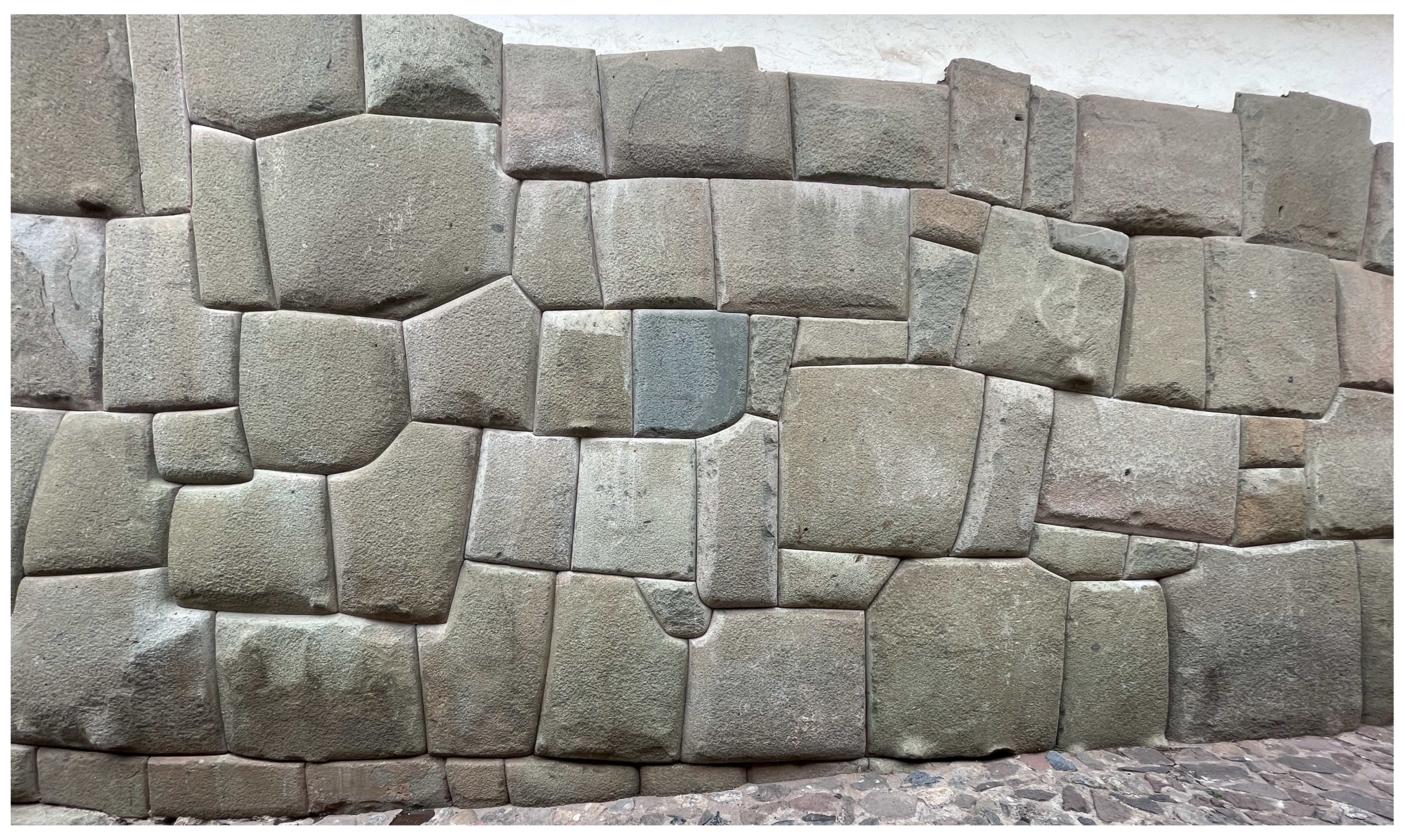
Photo 6.
Cusco (V. M. Soroka, 2021).
As additional elements, pedestals (leads) and pyramids of the same height are used to help maintain the straightness and flatness of the wall (see more details in Section 2.11.3). During the process of laying the stone blocks, the verticality (set deviation from the vertical), straightness (curvature), and flatness of the wall being erected are controlled using the plumb line and construction cord. After wall assembling, some pedestals are removed, some are converted into bosses (see Section 3.1).
2.2. Pantograph application for fabrication of the polygonal masonry blocks by casting
Using the proposed method, it is also possible to obtain large blocks of concrete, [47] geopolymeric concrete, [48] lime, artificial granite [49,50,51,52] and other materials by casting them into a mold. Using the pantograph, the reduced clay model of a block is enlarged to the desired size. The enlarged clay model is made hollow to reduce weight and shrinkage. Next, a mold is fabricated by the enlarged clay model.
Since shrinkage has a significant effect on the value of the interblock gap, it is desirable to make the cast blocks hollow to reduce shrinkage. Moreover, the cast blocks can be made of two components – a core (solid or hollow) of cheap concrete and a comparatively thin outer shell (“plaster” layer) of more expensive artificial granite. First, the core is cast. Then, after the end of the shrinkage, a fairly thin shell is cast over the core. Shrinkage of the shell is insignificant due to its small thickness. To ensure the strength and durability of the shell, its coefficient of thermal expansion (CTE) [46] should be as close as possible to the CTE of the concrete core. [53]
The enlarged clay models for hollow/solid core and for the outer shell are fabricated by the same reduced clay model of the block using the pantograph set to the appropriate enlargement factor. To increase adhesion of the shell to the core, radial grooves are made on the front surface of the enlarged core model, which continue on the side surfaces. The grooves are made either directly by the pantograph pointer (Pointer B), or by a wire loop attached to the pointer. Despite exfoliations on the granite blocks of some Peruvian structures that are similar to the described outer shell (see Photos 2–6, 16), the thicknesses of these exfoliations are small and thus these exfoliations should rather be attributed to the results of natural stone destruction [54] or unsuccessful restoration/conservation [24].
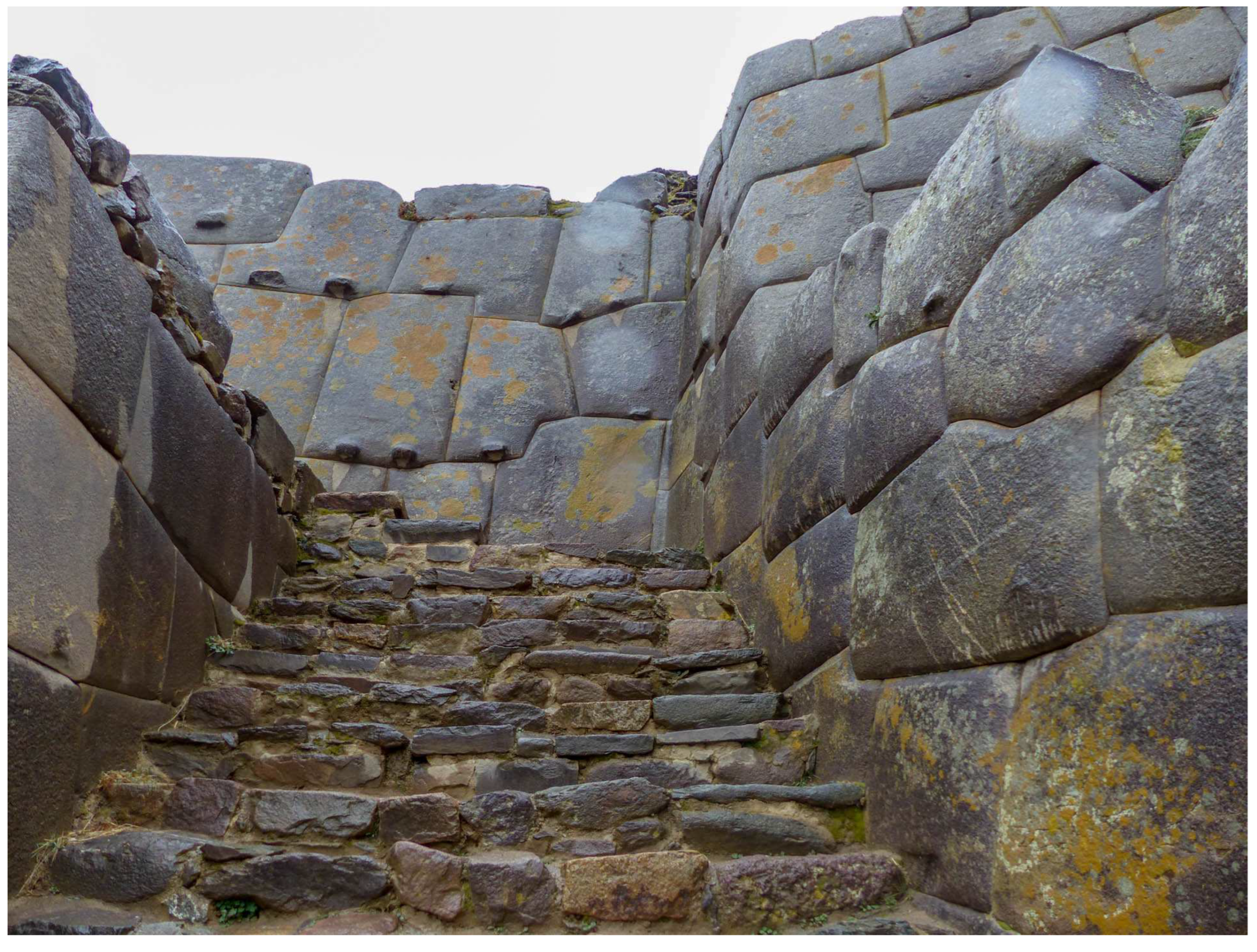
Photo 7.
Ollantaytambo (C. Jansen, M. Düerkop, 2016, www.travel-badger.com).
Photo 7.
Ollantaytambo (C. Jansen, M. Düerkop, 2016, www.travel-badger.com).
Although the proposed casting method is able to provide the polygonal masonry fabrication from large blocks tightly-abutted to each other, it is much more laborious in comparison with the mechanical processing method. The fact is that, besides the reduced model, this casting method requires additional fabrication of two more clay full-sized models of the block at least, followed by fabrication of two molds by these models – one for the concrete core, the other for the shell of artificial granite. To get a hollow core, one more full-sized clay model with minimal details is required, and one more casting mold is required in one of the fabrication alternatives.
Applying the 3D-pantograph to the reduced clay model and to an impression of its front face, it is possible to directly (i.e., without making intermediate full-sized clay models) fabricate the full-sized casting molds since the shape of the stone blocks used in polygonal masonry is quite simple (unlike a human sculpture, for example). To do this, an imprint of the front face of the reduced clay model is made in a clay pancake. After imprint solidification, the clay model is placed in its imprint and this packet is installed on its rotary platform (Table A in Figure 2) facedown. The clay billet for a full-sized casting mold is installed on the rotary platform of the enlarged model (Table B) with the open part (corresponds to the backside of the cast block) up.
First, with the 3D-pantograph, the side surfaces of the model (block base, top side, left and right sides) are transferred to the inner side surfaces of the casting mold. To transfer the side surfaces, a Π-shaped (in the vertical plane) pointer is installed in the pantograph instead of the conventional pointer; the tip of the Π-shaped pointer is directed opposite to the tip of the conventional pointer. After copying-scaling the side surface, the reduced clay model is removed from its imprint and the front face is transferred from the imprint onto the bottom of the casting mold by the 3D-pantograph equipped with the conventional straight pointer. If a split casting mold consisting of several parts is used, then the transfer of the model shape begins by transferring the imprint surface to the base (bottom) of the casting mold. Then the model is placed in the imprint and sequentially abutting the side parts of the casting mold to its base, the model side surfaces are transferred to the inner surfaces of these parts with the pantograph.
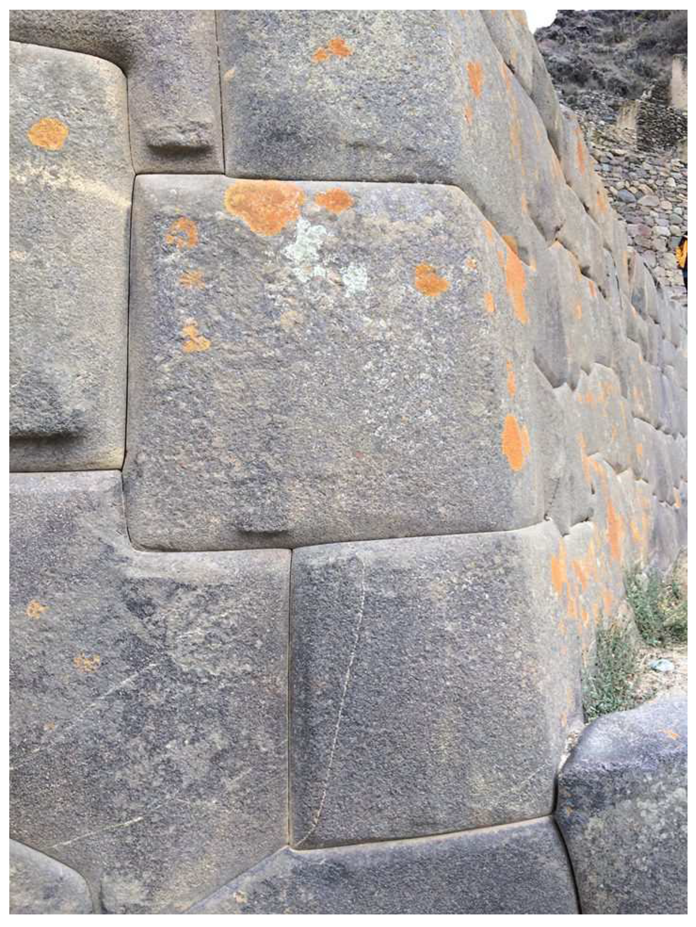
Photo 8.
Ollantaytambo (B. Everett, www.facebook.com/barry.everett.3).
Photo 8.
Ollantaytambo (B. Everett, www.facebook.com/barry.everett.3).
The casting method suggested can be simplified and made cheaper using a roughly mechanically processed natural stone as the core, which shape approximately repeats the shape of the final product in a reduced scale. However, in this case, the shell will have an unequal thickness, which, in turn, may affect the constancy of the gaps between the blocks (because of the non-uniform shrinkage). The required stone block acting as a core can be fabricated either simply by basic dimensions or by the reduced clay model using the pantograph. In the method under consideration, the backside of the cast block may not have an outer shell layer at all since in most buildings, taking up a gap between the blocks or taking care of the product appearance is not necessary at this location.
Since stone blocks in a polygonal masonry experience a weight load from several tons to several tens of tons, under certain circumstances, say, during tremors caused by an earthquake, the destruction of the outer hard but fragile shell of artificial granite may occur. The listed features show that although the presented casting method is capable to provide the desired result (small gaps), it is too complex and expensive for construction purposes, and it does not guarantee the necessary structure durability in the earthquake-prone region.
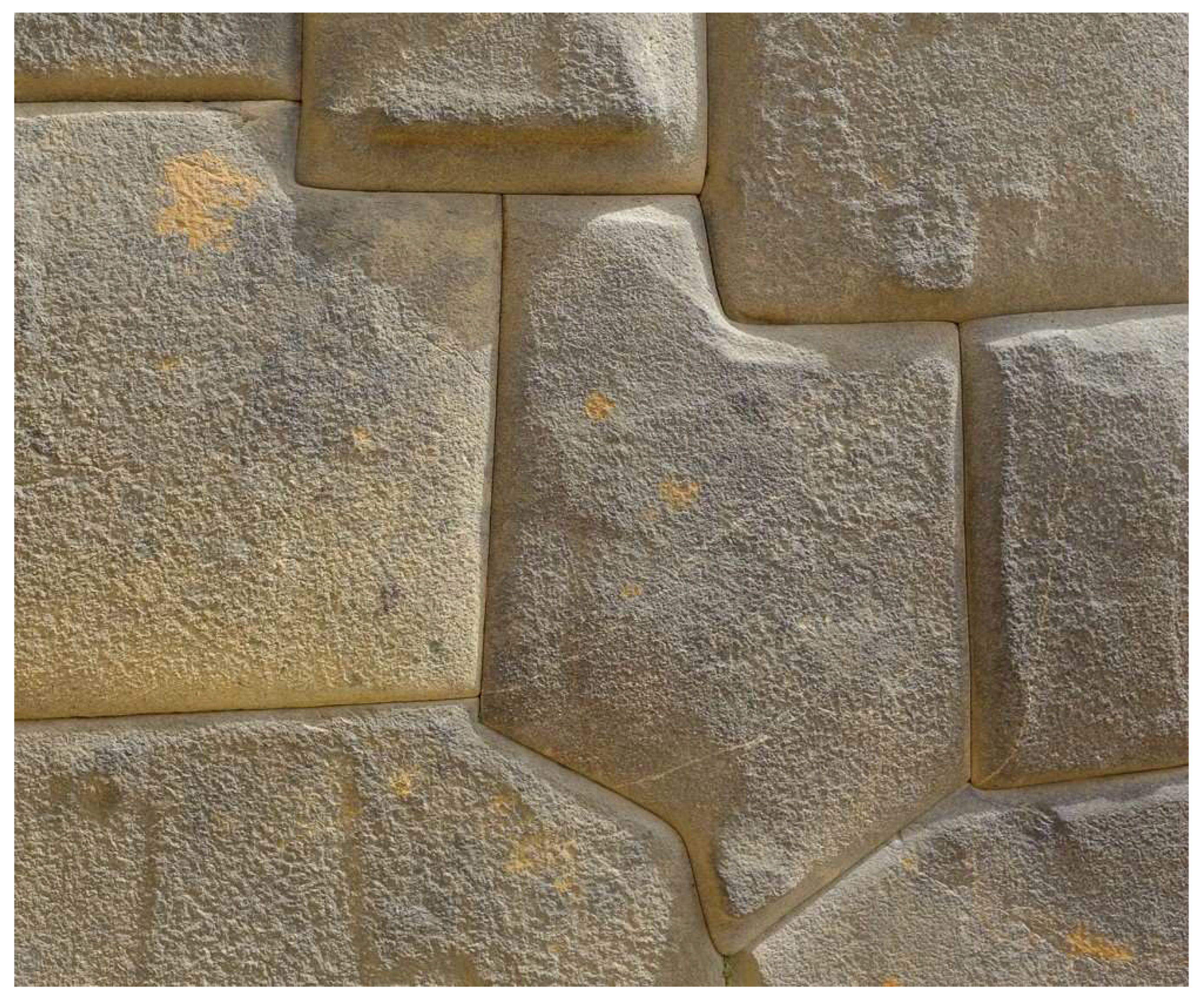
Photo 9.
Ollantaytambo (C. Boudou, 2013).
2.3. Usage of replicas
2.3.1. Replica-pancake
Not very complicated interfaces between large stone blocks are fabricated using replicas. A “pancake” of a constant thickness is pressed/rolled out of the clay. The raw pancake is put on a stone block, the surface of which should be replicated (the stone surface is previously covered with a composition that prevents clay sticking). After solidification, the replica-pancake is taken off. Periodically applying the obtained low weight replica-pancake to a heavy mating stone block, the excess material is gradually removed at the contact areas until full fitting of the replica to the block.
The smaller the relief to be transferred, the thinner the replica-pancake should be. In practice, the replica-pancake is able to transfer only comparatively smooth changes of a stone surface. While attempting to transfer small details, the replica-pancake becomes too thin, thus, it already bends under its own weight and breaks easily. In order to avoid the bending and prevent accidental damage during stone block processing, a fragile and still rather thin replica-pancake after separation from the original surface should be attached to some kind of a substrate-holder. By using the replica-pancake, it is impossible to transfer accurately the relief such as steep hills/pits since folds are formed in the replica's body. The folds result in changes of replica thickness, and, hence, the distortion of the copied topography. In general, the advantage of the replica-pancake is its simplicity; the disadvantage is a rather high error.
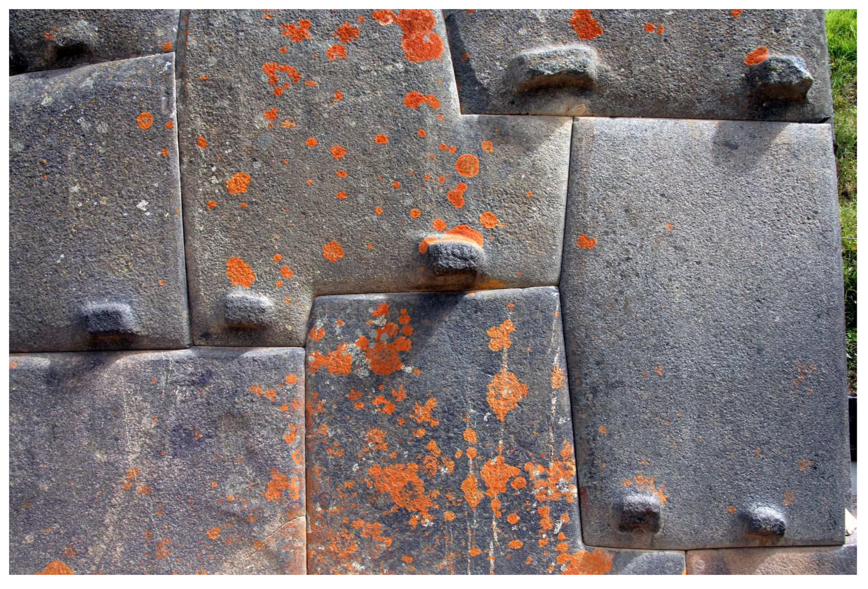
Photo 10.
Ollantaytambo (B. Foerster, 2009, hiddenincatours.com).
Photo 10.
Ollantaytambo (B. Foerster, 2009, hiddenincatours.com).
Since the replica-pancake is comparatively thin, its transversal shrinkage is not significant. Unlike the replica of replica described below, the transversal shrinkage in the replica-pancake cannot be corrected later in any way. To prevent the shrinkage-related longitudinal deformation, the material of the replica-pancake should have a small shrinkage coefficient and/or the replica-pancake should be pressed somehow against the original surface during the drying process. The replica-pancake should be pressed in such a way that its thickness would remain the same at any point. One can press the replica-pancake by putting an imprint of the original surface pre-made in a clay bar between a weight and the replica-pancake. The last improvement brings us close to the replica of the replica method discussed below.
2.3.2. Replica of replica
If a higher accuracy of the relief transfer is required than the replica-pancake is capable to provide, then a replica of the replica is produced. First, by applying a raw clay bar to the selected area of the stone block, an imprint of its surface is made. After solidification, another imprint is made in raw clay by the obtained replica. After drying, the replica of the replica is further used as a copy of the surface area of the stone block when making the mating part of the stone masonry.
In another method, a clay rim is installed along the perimeter of the selected area of the stone block, after that the formed container is filled with gypsum. After solidification, the obtained replica is imprinted in a raw clay or, having installed a rim on the replica, one fill the formed container with gypsum (the surface of the gypsum mold is pre covered with a substance preventing binding of the poured gypsum to the gypsum mold). After drying, the resulting replica of the replica is further used as a copy of the surface area of the stone block when making the mating part of the stone masonry.
The replicas were also used in the sites where the stone structures of large blocks were abutted upon rocks. The replica was taken from a pre-prepared rock section and then applied to the processing stone block or, vice versa, the replica was taken from a processed stone block and then applied to the processing rock. The used sequence of actions depended on what was more convenient in each particular case. Since very large stone blocks are like rocks – they being extremely difficult to move, the replicas were also used for joining large blocks to very large blocks and very large blocks to other very large blocks.
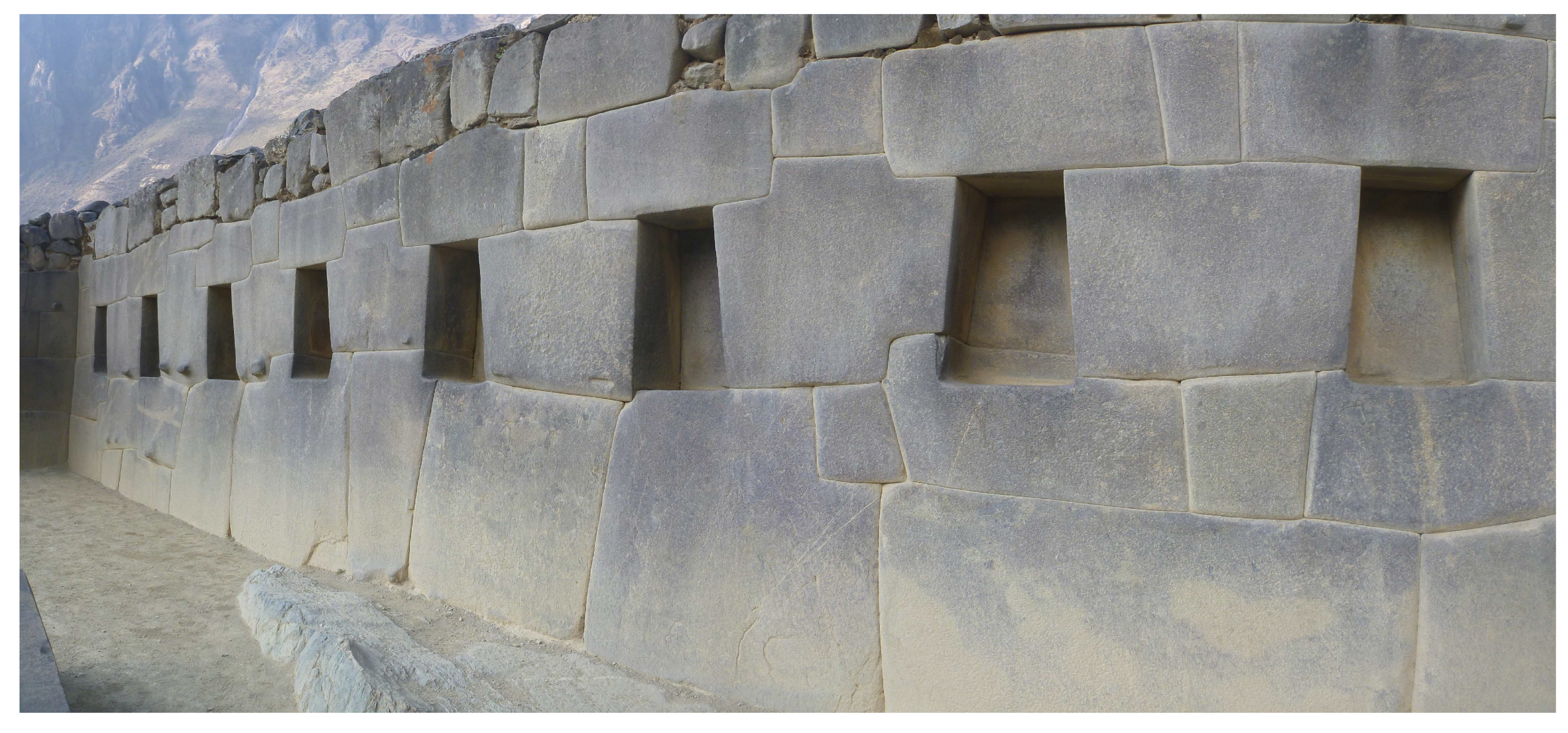
Photo 11.
The Temple of Ten Niches in Ollantaytambo (P. Adams, 2012, manboyinthepromisedlanddotcom.wordpress.com).
Photo 11.
The Temple of Ten Niches in Ollantaytambo (P. Adams, 2012, manboyinthepromisedlanddotcom.wordpress.com).
The larger are the sizes of a stone block, the larger and heavier are the replicas fabricated by it. Therefore, beginning from a certain size of the stone block, replicas have to be taken from separate sections of the stone block. To ensure the correct mutual position of the replicas on the processed mating surface of the block/rock, the sections of the neighboring replicas should be partially overlapped.
The disadvantages of the replicas are: a higher interface error of adjacent blocks in comparison with the pantograph and a higher fabrication laboriousness in comparison with the reduced block model. One of the sources of a replica of the replica error is clay/gypsum shrinkage. The shrinkage-related error of the replica-replica is twice that of a single replica. To reduce the shrinkage-caused error of the replica-replica, a thin layer of raw clay is applied to the replica; after that the replica is pressed against the original. As a result, raw clay fills the voids, after that the replica and the original are separated, then the replica is dried. Next, the similar operations are performed with the replica-replica. If necessary, the process is repeated.
The advantage of the replica is that just one of the mating surfaces of the adjacent blocks is processed upon a model (replica); the original surface is processed arbitrarily (independently). In contrast to the replica, it is necessary to process both mating surfaces by the model in the pantograph method. There are no arbitrarily processed surfaces in the pantograph method.
2.4. The main problem
What does a stonemason has to continuously do while fabricating blocks fitted to each other through a complicated profile? The stonemason has to repeatedly apply one stone to another in order to determine the areas where the excess material should be removed. When the stones are small, it is easy to do [6]. But how to do this, and quickly and precisely, when the weight of the stones is hundreds of kilograms or even several tons? The suggested methods just allow us to solve this problem. It is no longer necessary to repeatedly move a heavy mating block during processing.
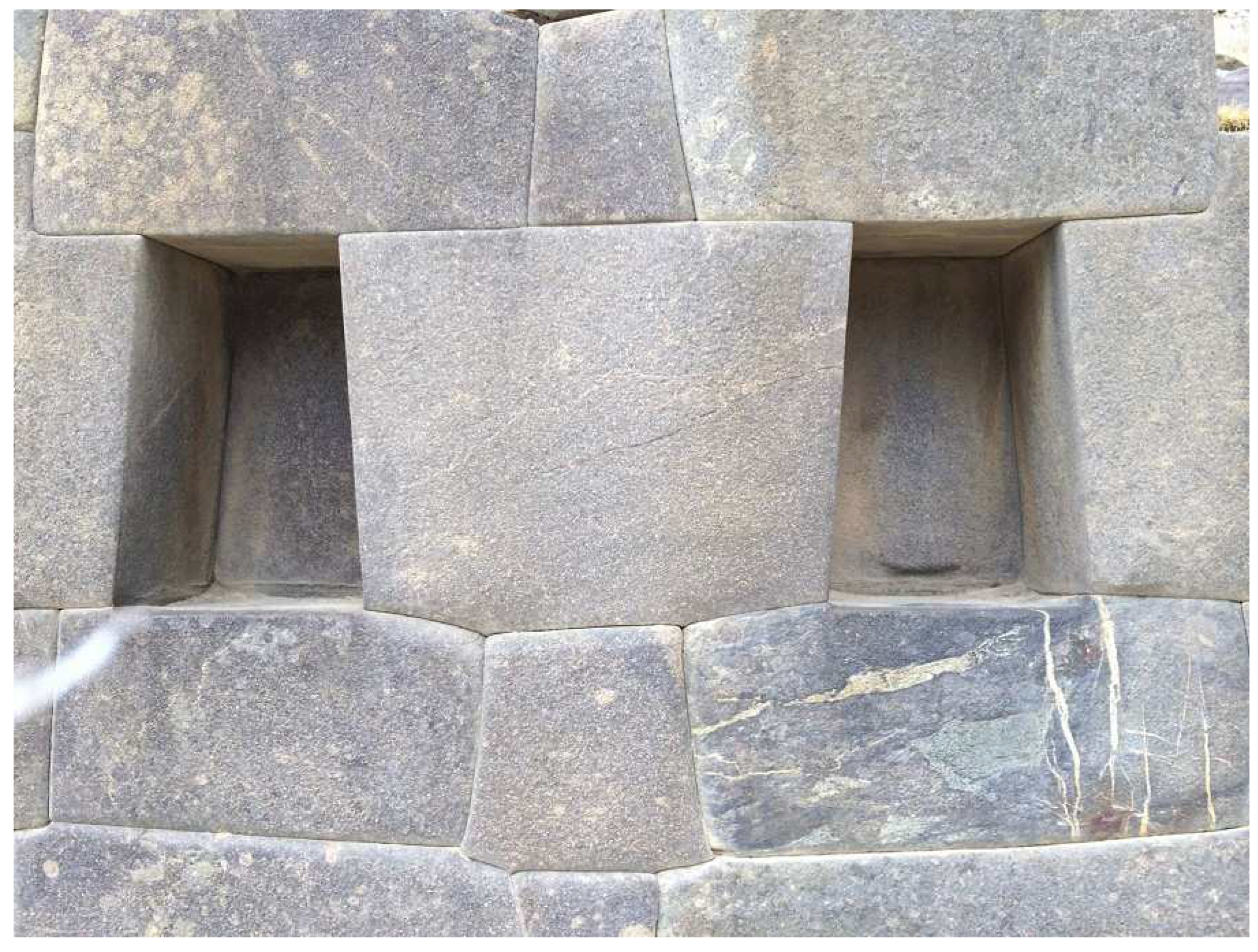
Photo 12.
The Temple of Ten Niches in Ollantaytambo (A. Fuchs, 2008, sy-akka.de/ wordpress). Pay attention to the symmetrical arrangement of the blocks in the masonry.
Photo 12.
The Temple of Ten Niches in Ollantaytambo (A. Fuchs, 2008, sy-akka.de/ wordpress). Pay attention to the symmetrical arrangement of the blocks in the masonry.
2.5. What else was the clay model of the object needed for?
It is always extremely useful:
- to have a small model of the object consisting of many parts of a complicated shape connected to each other in a complicated way;
- to turn each block in hands;
- to evaluate proportions more precisely;
- to correct the blocks if something is disliked in their shape or fitting;
- to assemble/disassemble the model wall to check the fundamental possibility of assembling the object containing locking elements;
- to assemble/disassemble the model wall to analyze the operations for moving, installing, and mounting heavy stone blocks;
- to see in advance how the object will look after the end of construction.
In those days, architects and builders had no computers to rotate a component in three-dimensional space on a monitor screen or, creating a virtual reality, wander around the future construction long before its erection. Even in our time, the making of scale models in architecture and planning did not lose its relevance.
It is well-known that the region, where the polygonal masonry was used, is earthquake-prone [2,3.4.5]. Therefore, by creating a model of the building with lock blocks and shaking it, one could see how the object would behave in an earthquake, after that make appropriate corrections to the project, if necessary. Other methods did not simply exist in those times, calculations were rough, and the intuition and experience could fail.
As shown above, both the concrete castings and the clay models have a shrinkage. Clay shrinkage makes 2-3% at best [47]. Consequently, the shrinkage-caused gaps should occur between the blocks of the polygonal masonry in both cases. Then what is the advantage of the clay model? Firstly, the shrinkage of the clay model is small, since the sizes of the model are small. Secondly, the clay model can be made hollow or a solid core can be put inside the model. Thirdly, it is not necessary for the clay model to be dried completely. Fourthly, the shrinkage-caused gaps in the clay model of the wall can always be eliminated by applying thin clay layers on the clay model blocks where needed. In this case, any requirements related to the strength and durability of the added clay layers are simply not applicable, since the clay model is just an auxiliary element of the construction process not experiencing heavy loads, which is thrown away after a short use.
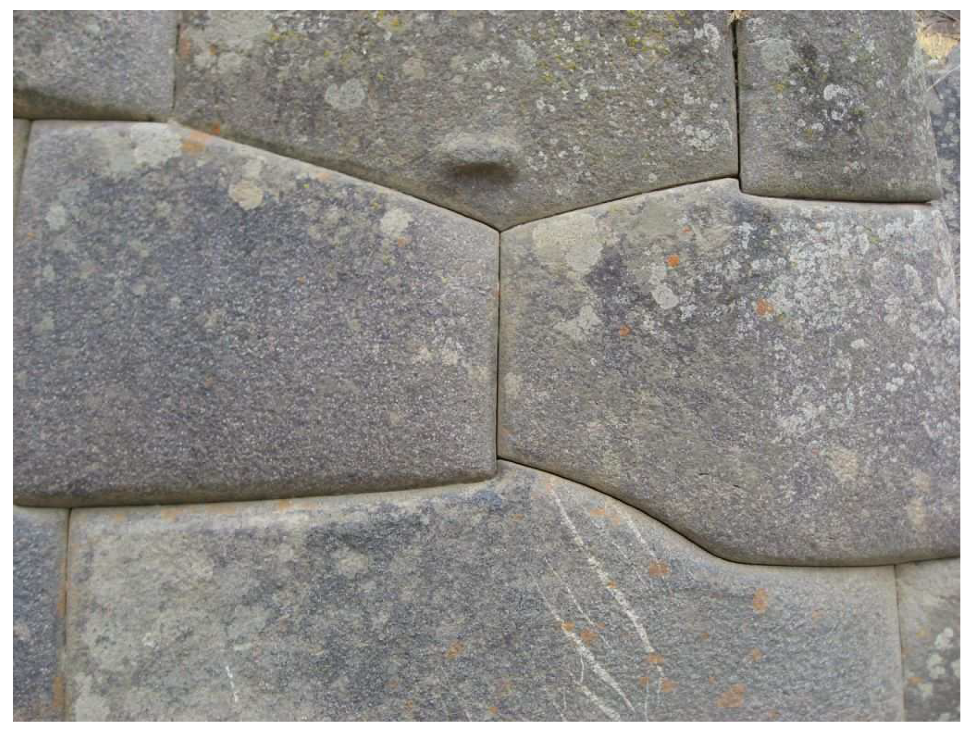
Photo 13.
Ollantaytambo (B. Everett, www.facebook.com/barry.everett.3).
Photo 13.
Ollantaytambo (B. Everett, www.facebook.com/barry.everett.3).
But it is useless to cover a concrete casting with a thin concrete layer of several millimeters thick, since the adhesion of this layer with the casting will not be strong enough and this layer will fall off or fail very soon under weight load and weather conditions. A thicker layer can be applied to the concrete casting covering all or most of the casting surface rather than a separate region (see Section 2.2). This layer will adhere better, but the construction technology for such layer formation is too complicated and expensive.
Thus, the signs of a recent construction (casting) and/or unsuccessful restoration [24] (Fortress Sacsayhuaman, the Tarawasi complex) are: cracks in blocks, traces of concrete mortar application, layered structure of disintegrated blocks (including the so-called “melted” stones), large gaps between blocks and non-parallelism of these gaps, falling apart polygonal masonry, failure to completely demount the masonry.
On the upper faces of a number of demounted stone blocks in Ollantaytambo, characteristic L- and U-shaped recesses for the bases of the blocks installed over draw attention [6,13]. Some of these recesses spread over two or even three adjacent blocks thereby providing bonding [8] of the blocks. According to the rules of stable equilibrium, the recesses ensure that the blocks would return to their initial position in the event of a small earthquake-caused horizontal displacement. The recesses under consideration in the upper faces of the blocks and the corresponding protruding parts at the bottom faces of the blocks installing over are fabricated while sculpturing the clay model.
2.6. What are the advantages of the pantograph over a replica?
When we apply a replica to a processing extensive surface of complicated topography, we do not clearly see where and how much material should be removed. Therefore, when using the replica, we should stain it by something, say, chalk or charcoal, and, applying it to the processing surface area, slightly rub it to mark the locations, where stone material should be removed. Remember, what a dentist does after filling the tooth. He puts a piece of carbon paper on the filling and asks to close your mouth and slightly rub it with teeth. After that, the dentist removes a little bit of the filling material in the marked place. Then he repeats the process several times until the teeth when closing would take the correct position.
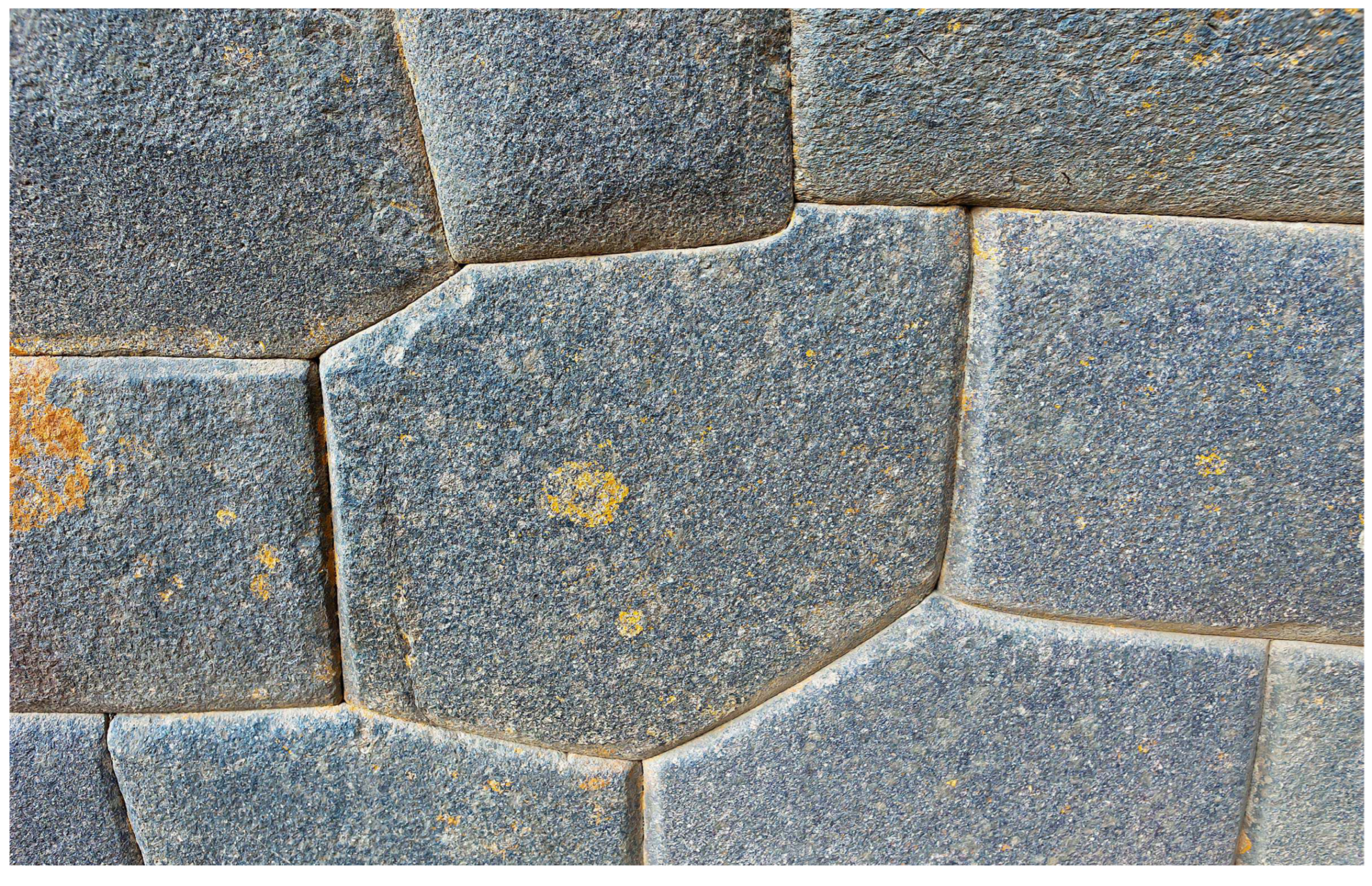
Photo 14.
Ollantaytambo (I. Otkalo, 2015, peru-info.me).
When working with the pantograph, the sharp probe (Pointer A) is applied to the clay model, and the sharp pointer (Pointer B), which is mechanically connected to the probe by means of the parallelogram mechanism, is applied to the processing surface of a billet. In contrast to the replica, due to the small area of the probe and pointer, the topography measurement is actually carried out in a surface point, and it is clearly visible in what exact point; the entire surface is completely open.
Moreover, the pantograph allows one to clearly determine the thickness of the material to be removed at any point to which the pointer is directed (see also Section 2.11.2). Therefore, the excess material can be removed for significantly fewer attempts. All these result in increasing productivity abruptly. The highest productivity is achieved when two people work with the pantograph. One person by the pantograph pointer shows a location (point) on the stone billet and reports the thickness of material that should be removed at this point, and the other person with the hammer and chisel removes the specified amount of the material.
Another advantage of the pantograph in comparison with the replica is that it is much faster, more accurate and easier to touch the clay model of the block with the almost weightless probe (the device is balanced by a counterweight) than to apply the relatively heavy replica to the stone billet, and then in addition to slightly rub with this replica by the billet.
Also, the pantograph allows to easily keep proportions set by an architect, that, in case of the replicas, have to be done by eye by spending a long time selecting billets of suitable sizes. Imagine that you need to accurately fit a structure into some unchangeable or difficult-to-change dimensions, say, between two rocky outcrops or into a cave. To do this, it is enough to measure the distance between the rocky outcrops and the size of the model, then divide first by second and set the obtained enlargement factor in the pantograph.
What else does the use of the clay model blocks and the pantograph give? Let it be required to make the outer side of the wall with a slope. To do this, it is sufficient to lay the raw clay model of the wall on the back side, install the stops setting the required slope, put a flat panel on top of the front side, and allocate above suitable weights. Instead of the weights, tightening clamps can be used. After some time, the clay model of the wall will be deformed properly. In the method, the specified angle can be kept very accurately along the whole length of the wall.
2.7. Reverse approach: clay model creation by a stone billet, formation of the interface surface and its transfer on the stone billet
According to the method described above, first, a reduced clay model was created by a sketch, and then the stone billet was selected for each block of the model. This approach allows us to repeat many times a section of the wall (if necessary, at different scales) using the same clay model each time (see a probable example of such masonry in Ref. [55]). The drawback of the method is the large volume of the chipped off material of the stone billet. The analysis shows that a reverse method was mainly used for the polygonal masonry.
In the reverse method, first, a reduced clay model is created by a stone billet of arbitrary shape using the 3D-pantograph. To do this, a piece of raw clay is impaled on a pointed, say, three- or four-sided metal pin located in the center of the rotating platform intended for a model (Table A in Figure 2). Due to this pin, the model can be removed from the pantograph at any time and precisely returned to its original position.
As before, the clay model and the stone billet are put on the pantograph with their backsides down. The exception is the wall corner blocks forming an outer corner (see Photo 8). These blocks should be placed with the most lengthy front face down on the pantograph to provide access to the side faces to be processed. In such stone blocks, the front face, inaccessible for processing during copying, is dressed after the final assembly of the corner section of the wall.
Clay is added to those places of the model where it is not enough. Removal of clay excess is carried out directly with the metal pointer (Pointer A in Figure 2; instead of a tip, a suitable tool can be attached to the pointer, for example, a wire loop, cutter, scraper, etc.) of the pantograph, which probe (Pointer B) moves over the surface of the stone billet block vertically up, then a small turn of the platform with the billet (Table B) around the vertical axis, then down, again a small turn, again up, etc. [33]. Owing to the pantograph, creation of the clay model body by the stone billet does not take much time.
At the next stage, a prototype of the wall is assembled from the obtained clay model blocks. The model blocks still have no mating surfaces. Taking into account the sizes and the shape of the model blocks, each block location is defined in the wall prototype. An architect-builder approximately layouts the contours of the future interfaces on the clay model of the wall, which should reflect: a conceived style, ensure strength and stability of the creating polygonal masonry, and minimize the labor of processing of the mounting surfaces. Further on, according to the accepted layout, the clay is cut out in the model block regions by which the blocks will adjoin each other.
Next, the wall model is assembled from the obtained model blocks. By small corrections, the blocks are matched more precisely to each other. If the block model was occasionally damaged during the manipulations, the shape of the model in any location can always be restored by placing the block model back on the pantograph (on the above indicated pin) and by comparing with the shape of the original stone billet.
Then, the wall is being dried. First, the bottom course is dried, then the next one, and so on. During the drying-shrinkage process, the model blocks are matched more closely under their own weight and with small corrections of the builder. If a shrinkage-resulted gap appears between the model blocks, it is eliminated by putting clay layers of the corresponding thicknesses on the model blocks at their interface.
At the final stage, the model wall is disassembled. A clay model of a block is put back on the pantograph (on the above indicated pin) and the mounting sites are transferred on the stone billet corresponding to this model block using the hammer and chisel.
In the described method, the stone block is installed in the pantograph at least twice. To accurately return the stone block to its initial position, two lines radially diverging from the center of the platform (Table B) can be plotted on the platform. At the first installation of the stone block, alignment marks are applied to the surface of the stone with paint in the places where the lines come out from under the block. Processing of the backsides of the stone blocks is carried out after assembling a bearing wall.
2.8. Several more advantages of the pantograph
The use of the reduced clay model and pantograph allows block fabrication directly in the quarry where the stones are extracted [6,13]. As a result, the already finished stone blocks are delivered from the quarry to the construction site. This approach significantly reduces the weight of the transported blocks and overall cargo traffic. Moreover, such organization excludes a large amount of construction debris on the construction site, which needs to be also transported somewhere after all.
Both the pantograph method and the replica method use auxiliary elements. In the pantograph method, these are the clay model blocks; in the replica method, these are the replicas themselves. To mate stone blocks in the replica method, the side surface of the block must be divided into several overlapping sections, each of which requires its own replica. If you mentally attach to the side surface of a non-marginal stone block all the replicas made for it and by it, you will get a kind of a wheel, i.e., a fairly massive formation. If a replica of replica is used, then there will be two such “wheels” already. Thus, it is necessary to fabricate one “wheel” of replicas for each non-marginal block in the replica of replica method. Let us compare such a “wheel” of replicas with the small model blocks in the pantograph-based method. The advantages of the pantograph are obvious.
2.9. Method combining elements of the replica, clay model and pantograph methods
In the beginning, every second stone block of the first course is installed on the site of the future structure (see Figure 3). The empty positions between these blocks will be occupied by stone blocks, which will be fitted in-place to these initially installed blocks at the next stage using a full-sized clay model and the 3D-pantograph. The heights of the stone blocks installed between the initial blocks should be approximately two times the heights of the initial blocks. The base surfaces of the initially installed stone blocks are pre-treated properly to ensure their stability.
Besides the prepared base, the initially installed blocks have finally processed side faces also. Processing of the side faces is straightening of a complicated initial shape of the stone billet by surfaces close to the planes with the hammer and chisel. The slopes of the side faces of the initially installed blocks to the bases of these blocks should not exceed 90°, if possible, in order to facilitate the subsequent installation of the adjacent blocks. The similar rule is applied later for every second block of the subsequent courses of the polygonal masonry.
Next, the space between the initially installed blocks is filled with clay. Actually, clay models of the blocks are created at the scale 1:1 in the spaces between the initial blocks. The side surfaces of these models contacting at the left and right with the side surfaces of the initial blocks are, in fact, their replicas. To decrease weight of the full-sized clay models and reduce their shrinkage deformations during drying, the models are made hollow. If a shrinkage-resulted gap appears between the initial stone block and the clay model, it is eliminated by putting a raw clay layer of suitable thickness on the clay model.
After drying, the clay model of the block is removed from the structure and installed in the pantograph in the model place (Table A). The corresponding stone billet is installed in the copy place (Table B). The pantograph is adjusted to the scale 1:1 (at the given scale, the placement of the model and the copy in the pantograph is only determined by operation convenience). If necessary, one can quickly check the matching of the selected stone billet to the model with the pantograph.
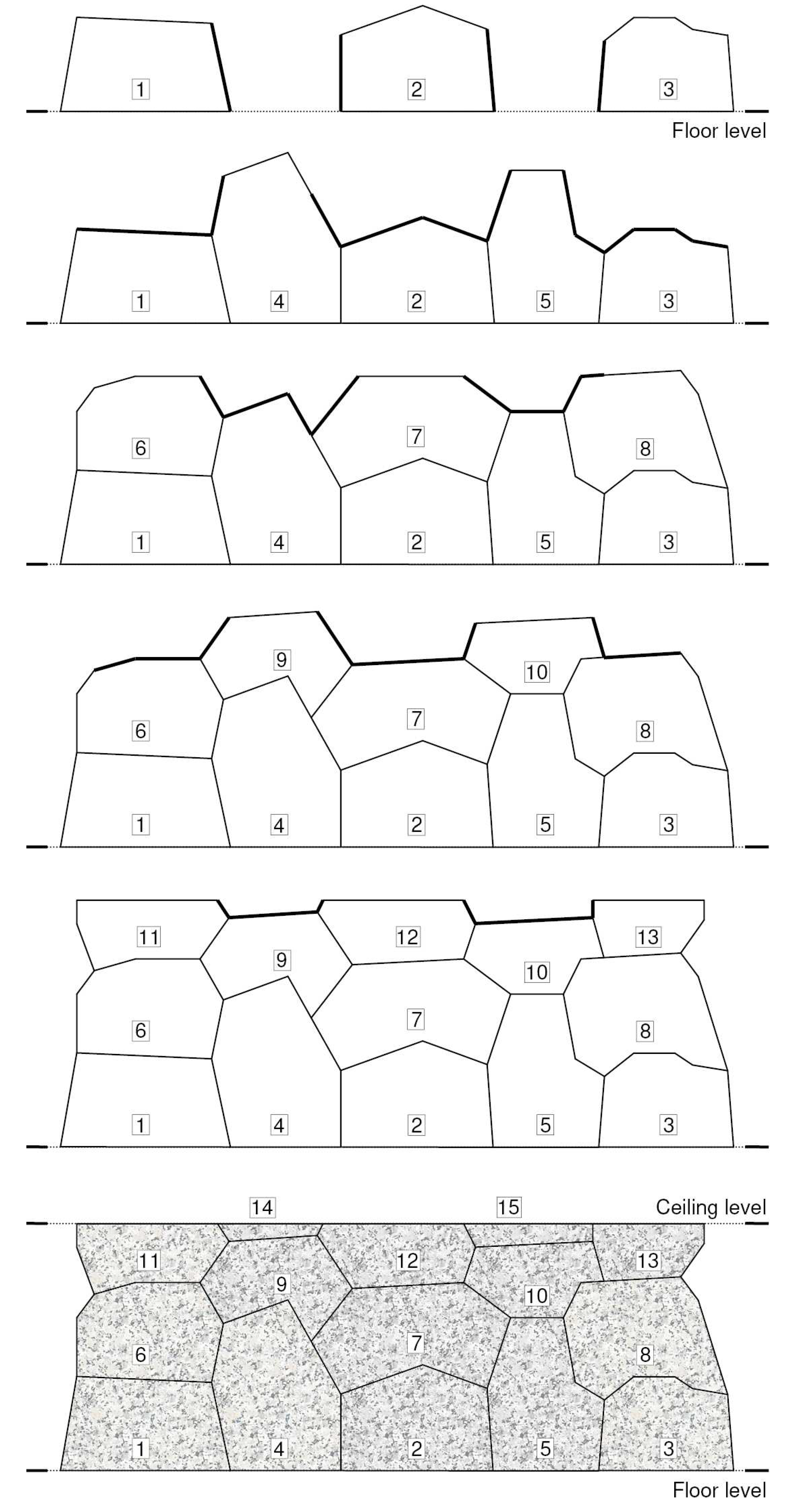
Figure 3.
Method of laying of polygonal blocks combining elements of the methods of replica, clay model and 3D-pantograph. The sections, by which the stone blocks are mated at each stage, are shown with a bold line. The numbers designate installation order of the blocks. The interfaces between the blocks are just depicted as rectilinear; in reality, these interfaces are curvilinear in more or less degree.
Next, the interface surfaces are transferred from the full-sized clay model to the stone billet using the pantograph, hammer and chisel, as described above. After transferring the interface surfaces, the rest (arbitrary) faces are formed on the remaining side surface of the stone billet. Processing of these faces is straightening of the complicated initial shape of the stone billet by surfaces close to the planes. Further, these faces will no longer be processed. The stone block obtained this way is finally put in its position in the polygonal masonry.
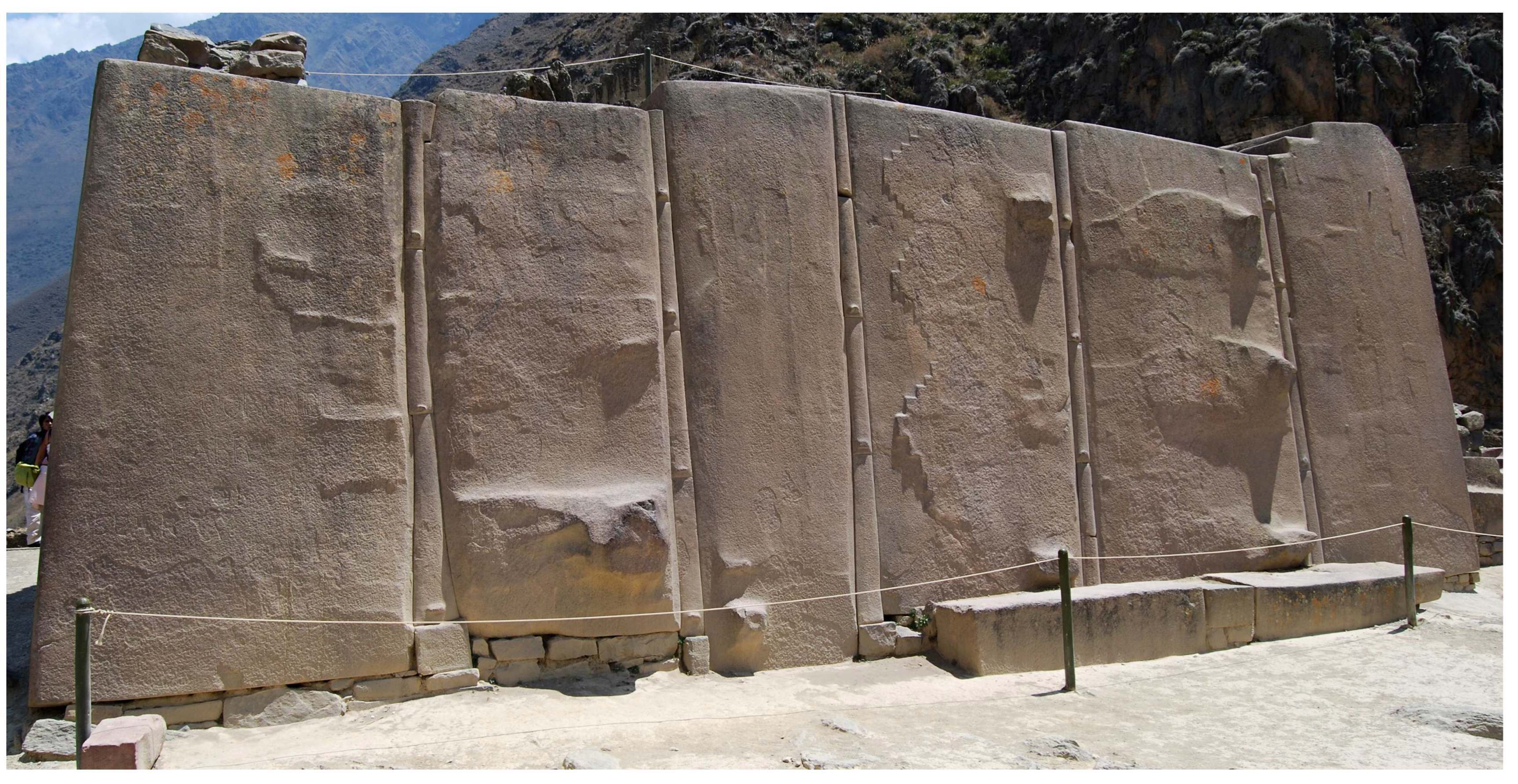
Photo 15.
The Wall of Six Monoliths in Ollantaytambo (P. Špindler, 2008, commons.wikimedia.org). Most likely, the Wall is built using the method combining elements of the methods of replica, clay model, and 3D-pantograph. The small stones under the megaliths indicate that the Wall seems to have been once reassembled, and possibly moved.
Having finished the first course, the next one is produced in the same way. As in the above methods, the stone blocks of an arbitrary shape are used in the described method as building material. The method provides a good vertical bonding of the blocks and a satisfactory horizontal one. Since the method has no a full-fledged clay model of the structure, to put together the original stone blocks well and thereby minimize the amount of material to be chipped off during processing, it is desirable to preliminarily lay out the stone blocks on the ground with the backside down, one next to the other.
The method disadvantage is the high laboriousness associated with the fabrication of the clay model of the block in the scale 1:1. Nevertheless, in comparison with the replica-replica method, this method is capable of providing a higher accuracy of the interface between the contacting surfaces when it is necessary. As in the replica cases, a half of the side surface of the non-marginal stone blocks is processed arbitrarily in this method.
The Wall of Six Monoliths at Ollantaytambo (see Photo 15) consisting of one conditional course was constructed according to the described method most likely. Leaving aside the architectural appearance of the monument for a while, let us ask the question: why are the monoliths not connected to each other directly, but require intermediate inserts (shims)? The fact is that the use of replicas on such extended contact areas of the side surfaces of the monoliths is unable to provide a zero gap. Therefore, the intermediate inserts were needed to connect the monoliths.
To emphasize the gigantic dimensions of the monoliths, the inserts should significantly differ from the monoliths in width. Since fabrication and installation of a single narrow monolith-high insert is even more difficult technical task than the direct fitting of the neighboring monoliths, the intermediate inserts were divided into 3-5 separate parts. Each insert was fabricated in-place and installed sequentially one after another – first, a row (conditional) of the lowest inserts, then the next row of inserts, etc. During wall assembly, some of the intermediate inserts were lowered on their place from top to bottom, some were installed from the front or back side of the wall.
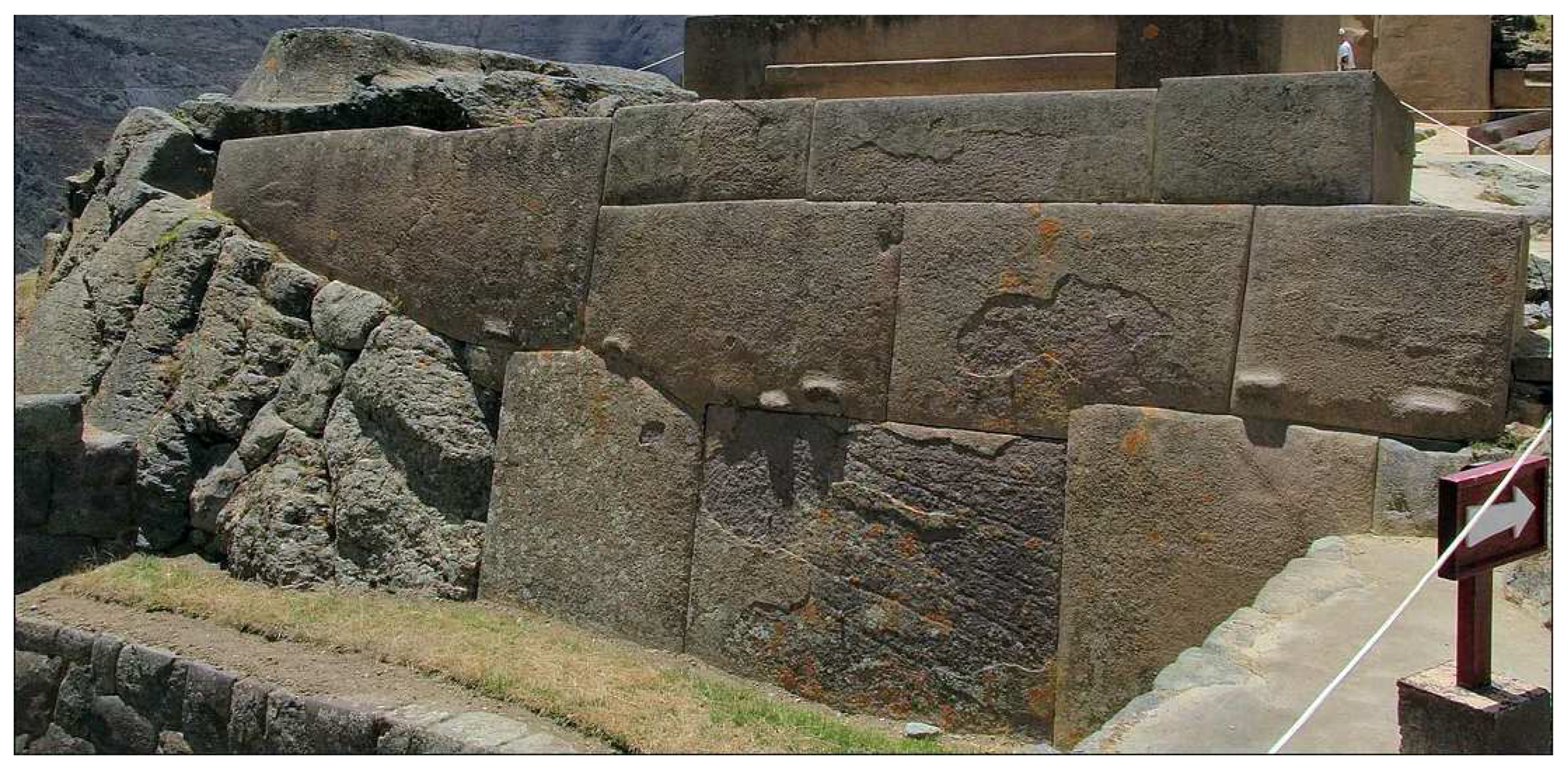
Photo 16.
Ollantaytambo (E. Berzin, 2015, allenatore.livejournal.com).
Photo 16.
Ollantaytambo (E. Berzin, 2015, allenatore.livejournal.com).
One should pay attention to the small stones on which the monoliths rest. These stones ensure taking up the side gaps between the monoliths and the lowest narrow vertical inserts (see Section 2.1). However, the considered method of block joining does not need such position adjustment, since fabrication of the intermediate inserts here is carried out in-place. It follows that the Wall of Six Monoliths was once reassembled and may have been originally located in other place. The need for reassembly could arise due to insufficiently thorough preparation of the monument basement or in connection with blocks that are falling apart after an earthquake, etc. Apparently, at the final construction stage, the small stones in the base of the reassembled monument were supposed to be hidden by a floor level.
2.10. “Planetary” pantograph for use in construction
The modern 3D-pantographs used by sculptors have two synchronously rotating platforms. A model is installed on one platform (see Table A in Figure 2), and the enlarged copy of the model is installed on the other platform (Table B). Usually the enlarged copy is hollow, so its weight is not high, as a rule. The reinforced platform of such pantograph applied for construction purposes is able to withstand stone billets weighing up to 500 kg.
When a sculpture is large and heavy, its model is divided into several parts. An enlarged stone copy is fabricated for each such part; then a large sculpture is assembled from the obtained enlarged copies of these parts. However, this is not our case. By the way, the polygonal Face Towers (see Photo 17) of the Cambodian temple complex Angkor [56] were apparently made according to a similar technology. Regarding the Face Towers, it is also worth noting that they have symmetry, which, in turn, may indicate the use of a 3D-pantograph for their fabrication (see details in Section 3.8).
The modern 3D-pantograph is not suitable for working with large and heavy stone billets. Instead of the existing design, one can offer the following “planetary” pantograph. The heavy stone billet in such pantograph is simply installed on a plane immovable horizontal base 2 (see Figure 4) and the frame 3, on which the platform 1 with the reduced clay model and the pantograph boom (not shown in the figure) are attached, is turning in the horizontal plane around the stationary standing billet during work. As the frame turns, the clay model also turns around its vertical axis at the same angle in the opposite direction (actually retains its original orientation in the space) using an appropriate mechanism. One revolution of the support point (Pivot in Figure 2) of the pantograph boom around the stationary billet corresponds to one revolution of the clay model around its axis.

Photo 17.
The polygonal Face Towers of the Angkor temple complex, Cambodia (D. Wilmot, 2005, www.flickr.com/photos/david_wilmot). According to the proposed technology, the reduced clay model of a Face Tower consisted of a number of parts forming a polygonal masonry. For each part of the clay model, an enlarged stone copy was produced using the 3D-pantograph. The Face Tower was assembled from the enlarged stone copies of these parts. The Face Towers have symmetry, which may also speak in favor of using a 3D-pantograph for their fabrication.
Due to the large sizes of the construction pantograph, the mechanism synchronizing rotation of the model with the rotation of the frame around the stationary billet turns out to be cumbersome and heavy. To simplify design and reduce cost of the planetary construction pantograph as well as to decrease a backlash-related error, any mechanism can be abandoned at all. To do this, just divide the round base site on which the billet is rested and the model platform by the same number of sectors with a step equal to, say, 11.25° (2π/32). Now, during the work, after rotating the pantograph frame around the billet by one sector, for example, counterclockwise, one just needs to manually rotate the model by one sector clockwise. The frame and model rotation discontinuity is leveled by the operation of the parallelogram mechanism located on the boom.
To rotate the pantograph around the processing stone block, there is an annular groove 6 of rectangular profile in the upper cylindrical part of the immovable base 2 on the side surface, into which two halves of a flat metal ring 4 are inserted that forms a sliding bearing with the base. Two flat plates 10 are tightly attached to the flat ring 4. The flat plates 10 have clamps 11 to attach the ring to the edges of the I-beam of the frame 3. To set the necessary pantograph magnification factor, the frame 3 is moved (shown with arrows) relative to the stationary base 2 after loosening the bolts 12 of the clamps 11. After setting the magnification factor by locating the support point of the pantograph boom at a certain distance from the center of the immovable cylindrical base 2, the position of the frame 3 is fixed by tightening the bolts 12 of the clamps 11.
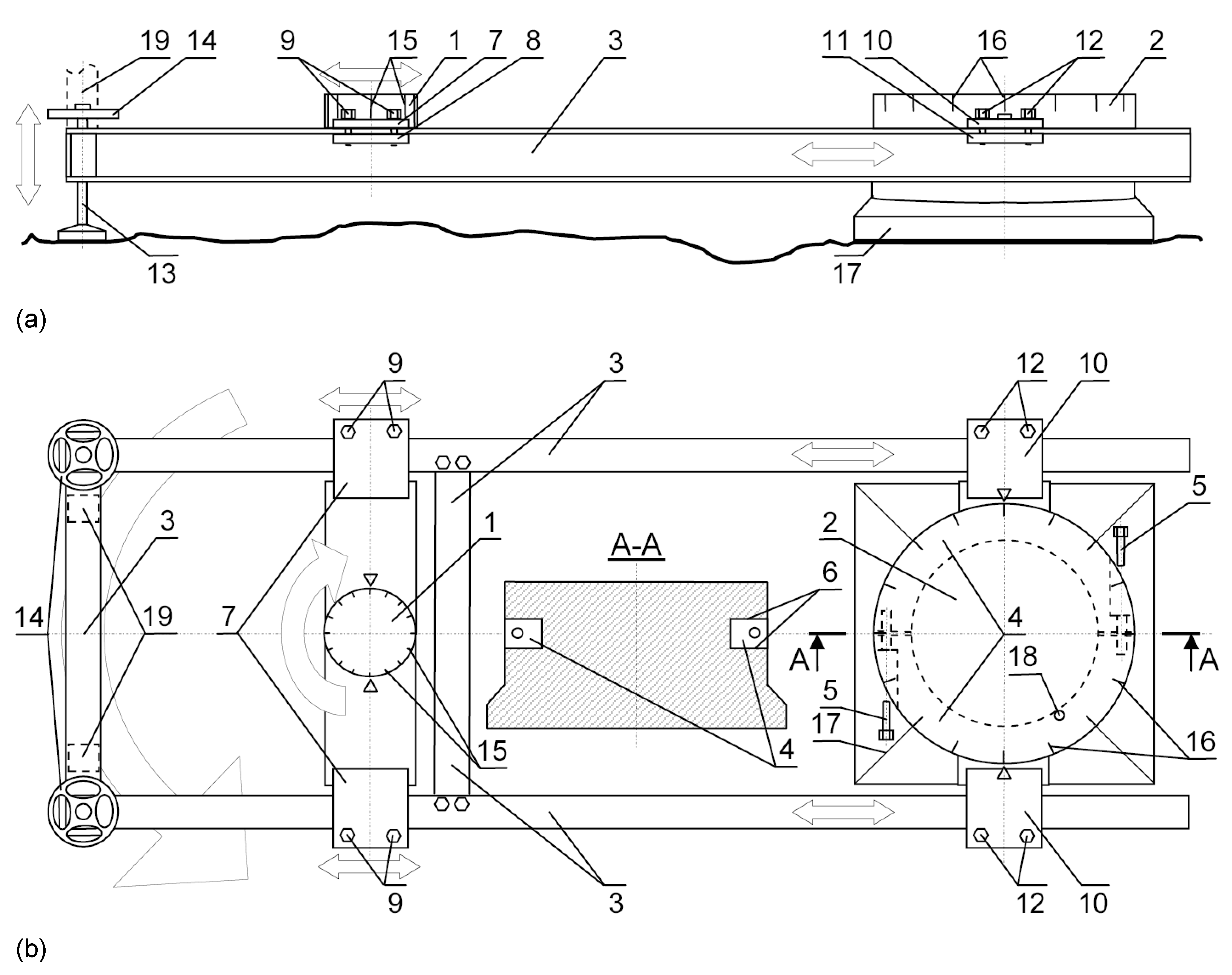
Figure 4.
Planetary construction 3D-pantograph: 1 is the rotary platform on which a reduced clay model of a stone block is installed; 2 is an immovable base on which a stone block being processed is installed; 3 is the pantograph frame assembled of I-beams; 4 is a two-part sliding bearing consisting of two halves of a ring that provides pantograph rotation around the immovable base 2 in the horizontal plane; 5 are bolts connecting two halves of the ring of the two-part sliding bearing 4; 6 is an annular groove of the rectangular cross-section in the cylindrical part of the immovable base 2 into which the ring of the two-part sliding bearing 4 is inserted; 7 are flat plates intending to attach the rotary platform 1 to the frame 3 using clamps 8 and bolts 9; 10 are flat plates intending to attach the ring of the two-part sliding bearing 4 to the frame 3 using clamps 11 and bolts 12; 13 are screw supports for leveling the rotary platform 1 in the horizontal plane; 14 are hand wheels of the screw supports; 15 are marks of the 11.25°-sectors dividing the circle of the rotary platform 1; 16 are marks of the 11.25°-sectors dividing the circle of the immovable base 2; 17 is a wide support portion of the immovable base 2; 18 is a plugged hole intended for lubrication of the two-part sliding bearing; 19 are installation locations for a vertical frame supporting the pantograph boom with the parallelogram mechanism and a counterweight (see Figure 2). Pantograph (a) front, (b) top view.
By means of the bolts 5 fastening the halves of the ring of the two-part bearing 4, it is adjusted how tight the sliding bearing will rotate when turning the pantograph frame 3 around the immovable base 2. Although the frame along with the boom, parallelogram, counterweight, model platform and model itself is heavy enough, the bolts 5 fastening the ring 4 can be tightened for time of processing to additionally fix the frame relative to the stone billet after turning the frame by one sector and loosened before the next frame turn by the next sector. By tightening the bolts 5 of the ring 4, a gap directly affecting the value of the copying error is taken up also. Moreover, periodical tightening of these bolts allows to take up a gap related to a wear of the inner cylindrical surface of the metal ring 4 while it is rubbing in the groove 6 against the harder immovable base 2. To decrease friction in the bearing 4 and reduce its wear, the bearing is lubricated with oil. To supply the bearing with lubrication, a small hole 18 equipped with a plug is provided in the base 2.
The frame 3 of the planetary pantograph as the frame of the pantograph in Figure 2 is assembled from I-beams but other types of beams can be used. The stationary base 2 can be installed directly on the ground of a construction site. To increase stability, the lower part of the base 2 has an extension 17. For better fixation of the base 2, its lower part 17 can be partially buried in the ground. After installing the base 2 on leveled, compacted soil, the upper plane of the base is strictly aligned horizontally using a plumb level [57,58]. For some time after a stone billet installation on the base 2, ones periodically check using the plumb level whether the base has a tumble in relation to the horizon or not. In case of a tumble, the base 2 is leveled again. After each movement of the frame 3 of the pantograph by a sector around the processing stone block, ones rotate the hand wheels 14 of the screw supports 13 and align the plane of the platform 1 with the clay model with the horizontal plane using the plumb level installed on this platform.
After rotation of the platform 1 with a clay model by a sector, it is fixed with a locking screw (not shown in the figure) to prevent an accidental rotation of this platform relative to the current position of the frame (position of the processed block) during operation. The vertical frame provided with a counterweight, the pantograph boom, and the parallelogram mechanism mounted on the boom (see Figure 2) is not shown in Figure 4, just its installation locations 19 are indicated. The stationary base 2 of the pantograph is cast from concrete. To form the sliding bearing, the metal ring of the bearing 4 is inserted in the casting mold bodily. To make it easier to drag the stone billet on the construction pantograph and drag the finished stone block off the pantograph, an inclined ramp is temporarily adjacent to the immovable base 2 on the right side.
Unlike the existing pantograph, the planetary pantograph requires more working space, and the person using the planetary pantograph has to move the pantograph frame around the stone block under processing and align the platform with the model in the horizontal plane after each movement during work. These features can be attributed to the shortcomings of the planetary pantograph, which, however, are not critical at all in the construction field.
2.11. Topography translator based on the double parallelogram mechanism
One can suggest a plain mechanical device – a topography translator (see Figure 5), which, in the case of a comparatively simple polygonal masonry, allows to perform quite acceptable joining of the surfaces of the adjacent stone blocks in-place. The comparatively simple polygonal masonry is a masonry that does not require the preliminary fabrication of an object model. The blocks in such masonry have a comparatively simple shape, they are joined to each other mainly along the side surface (backsides of the blocks are not processed, as a rule) using simple L- or U-shaped recesses, and do not contain complex three-dimensional locking elements. To process the stone blocks using the topography translator, both the mating blocks are put on the ground on their backsides. Thus, the side surface (base, top side, and side faces of the blocks) to be processed would be arranged vertically in this method.
First, the mating area of the surface of the first block is subjected to an arbitrary processing. During the processing, the surface in this area is made smoothly changing, close to a plane. Such a surface is obtained when a stonemason makes a flat surface manually “by eye” without deviation control of the treated surface from the plane in any way.
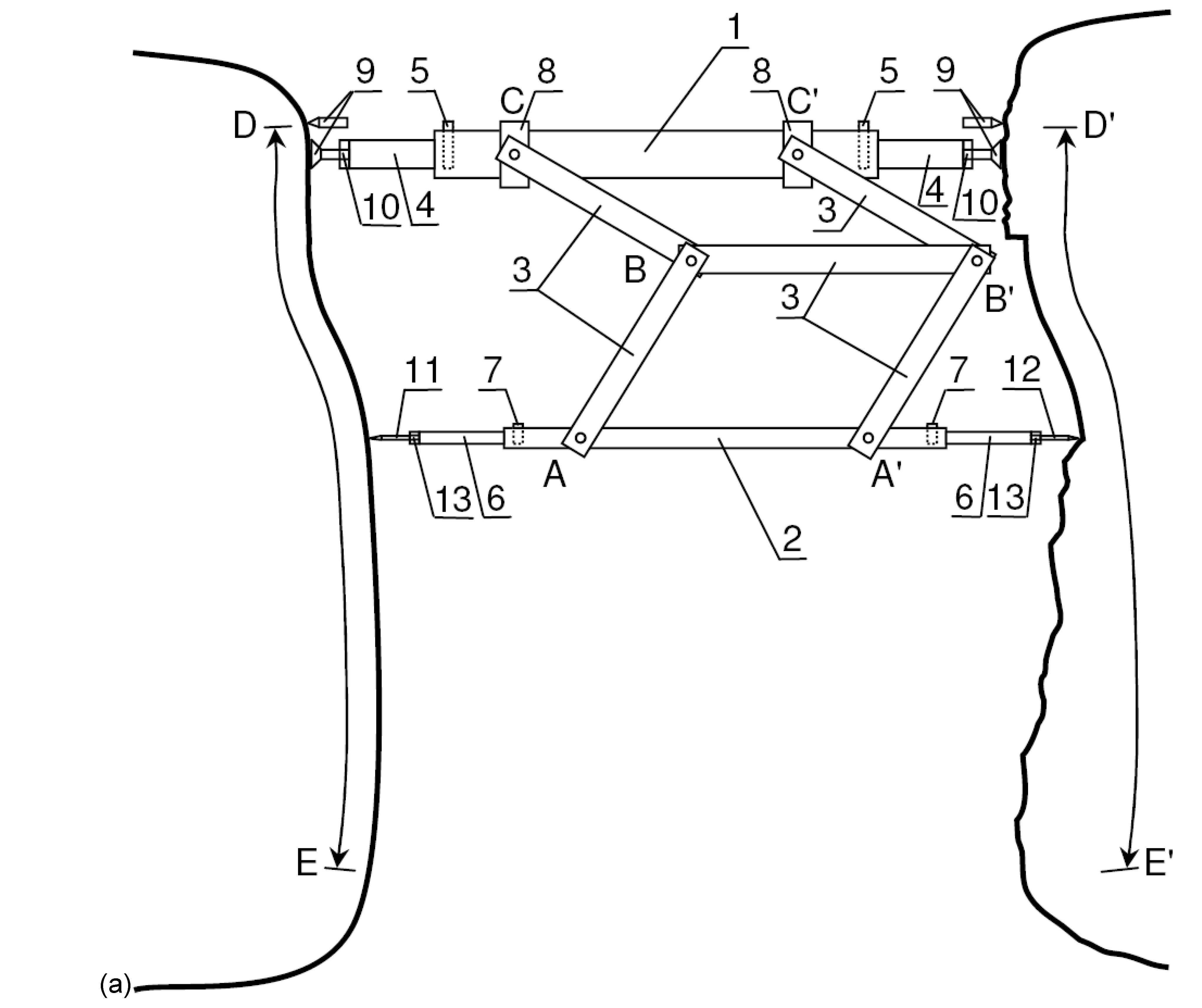
Figure 5.
Topography translator: 1 is a carrying rod; 2 is a measuring rod; 3 is a double parallelogram mechanism (AB=A'B'=BC=B'C', AA'=BB'=CC'); 4 are retractable sections for coarse set of length of the carrying rod; 5 are pins locking positions of the retractable sections of the carrying rod; 6 are retractable sections for coarse adjustment of length of the measuring rod; 7 are pins locking positions of the retractable sections of the measuring rod; 8 are cylindrical hinges providing free rotation of the measuring rod along with the double parallelogram mechanism around the carrying rod; 9 are supports (pointed or with a flat foot) of the carrying rod, by unscrewing of which, the carrying rod is set as a strut between two mating stone blocks; 10 are lock-nuts fixing the positions of the supports of the carrying rod; 11 is the probe of the measuring rod; 12 is the pointer of the measuring rod; 13 are the lock-nuts fixing positions of the probe and pointer of the measuring rod; 14 are cylindrical hinges providing free rotation of the measuring rod around its own axis; DE is an arbitrarily-processed section of the side surface of the previous stone block; D'E' is a section of the side surface of the current stone block processed using the translator. Installation of the carrying rod as a strut between the blocks (a) perpendicular to the mating surfaces using the flat foot supports, (b) at an angle to the mating surfaces using the pointed supports. (b) The translator equipped with additional hinges 14, a bent probe 11, and a bent pointer 12 to process the U-shaped recesses.
Then, a second stone block is put near the first block. The second stone block is located so that the surface areas under the fitting are opposite each other. The distance between the blocks is set such (60-80 cm) that a stonemason can accommodate between the blocks and is capable to work with a hammer and chisel in the space between these blocks without much trouble. Next, the proposed topography translator is installed between the blocks as a strut, so the stonemason can use it to transfer the inversed topography of the surface area of the first block previously processed in an arbitrary manner to the second block.
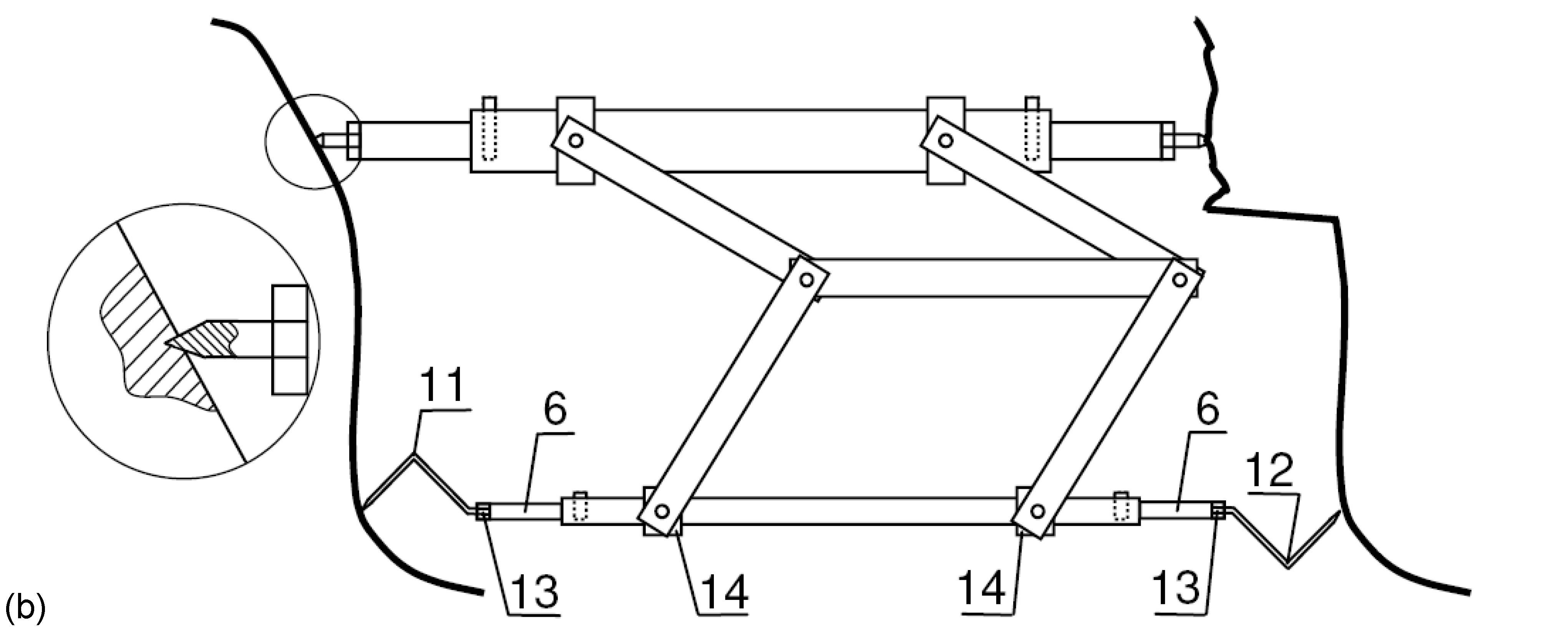
Figure 5.
Continuation.
In general, the lateral surface of a stone block is a set of the mentioned conditionally flat surface sections. The conditionally flat sections can adjoin each other forming a sharp boundary, or they can pass into each other quite smoothly as in the reciprocal parts of the L-shaped recesses. The U-shaped recesses are reduced to a pair of counter-located L-shaped recesses. Further, let us describe in more detail the translator and the stone block processing sequence based on its application.
2.11.1. Topography translator design
The topography translator consists of two parallel rods connected to each other by means of a double parallelogram mechanism (see Figure 5). The double parallelogram mechanism belongs to the hinge-lever guiding mechanisms, it has two degrees of freedom and consists of seven links such that AB=A'B'=BC=B'C' and AA'=BB'=CC' [31]. In the translator under consideration, the rod bodies are part of the double parallelogram mechanism. The rod with a bigger cross-section will be called a carrying rod; the rod with a smaller cross-section will be called a measuring rod. Using a telescopic or other joint, the length of the rods can be changed roughly by sliding in and out the edge sections along the rod. After the end of the rough adjustment of the rod lengths, the relative positions of the edge sections are fixed with pins.
Tip-supports are screwed in into the ends of the carrying rod, and by unscrewing them one can fix the translator rod securely like a strut on the processed area between the mating stone blocks. Pointed tips are screwed in into the both ends of the measuring rod. The pointed tip directed to the pre-treated surface of the first block will be called a probe; and the pointed tip directed to the processing surface of the second block will be called a pointer. By screwing in/out the threaded pointed tips, the length of the measuring rod is set precisely. The set positions of the supports and the pointed tips are fixed with corresponding lock-nuts.
If the carrying rod is installed as a strut between the blocks perpendicular to the mating surfaces, then the flat foot supports are used (see Figure 5a). If the carrying rod is installed as a strut with a significant tilt to the mating surfaces, then the pointed supports are used (see Figure 5b). In the latter case, before installing the carrying rod, small recesses are made in the stones at the installation locations of the supports. The recesses are necessary to prevent slipping of the carrying rod supports.
Since the translator have to transfer the spatial topography of the surface, and the double parallelogram mechanism has only two degrees of freedom, the parallelogram mechanism is attached to the carrying rod through cylindrical hinges. Thus, due to the cylindrical hinges of the carrying rod, the measuring rod together with the double parallelogram mechanism can rotate freely around the carrying rod. Such rotation makes it possible to “readout” the transferred topography by the probe of the measuring rod around the installation position of the carrying rod.
2.11.2. Order of operation with the topography translator
If the carrying rod of the translator is installed near the location of the longest distance between the blocks, then the longest distance is set in the measuring rod in-place, and the topography transfer starts from this location. Generally, the carrying rod can be installed at any location which is convenient for the stonemason. In practice, it is often convenient to install the carrying rod closer to a block edge, and to begin topography transfer (translation) from there.
After installing the carrying rod and setting the necessary length of the measuring rod, the probe tip of the measuring rod is brought into the contact with the pre-treated surface of the first stone block (shown in the figure on the left). As a result, the pointer tip of the measuring rod will show the point on the counter processing surface of the second block (shown in the figure on the right), where the stonemason should chip off material.
If one made the translator pointer sinkable into the retractable section of the measuring rod, spring-loaded, and equipped with a scale and an indicator (these elements are not shown in the figure) then the stonemason will know how much material should be chipped off at this point. The similar pointer device can also be used in the design of the 3D-pantograph. Thus, having information about the amount of material to be removed at each surface point, the stonemason performs the work in fewer chippings significantly improving his productivity.
The highest productivity is achieved when two people operate with the translator. One person with the translator pointer shows the location (point) on the stone block under processing and says the thickness of material that should be removed at this point, and the other person using the hammer and chisel removes the specified amount of the material.
The main purpose of the double parallelogram mechanism is to ensure the strict parallelism of the movement of the measuring rod. From the above description, it can be seen that the translator under consideration provides the same result on a separate mating section as the 3D-pantograph adjusted to the scale 1:1.
Translator accuracy is determined by gaps in the hinges and by bending deformations of the structural elements of the mechanism. To ensure structure rigidity, the bars and hinges used in the parallelograms have the appropriate cross-section sizes and stiffeners (not shown in the figure). To increase structure rigidity, besides the mentioned parallelogram mechanisms, additional identical parallelogram mechanisms can be used by attaching them both in parallel and in series (along the rods).
The translator mechanism has a limited movement space, which is a cylinder with 2AB radius (the axis of the cylinder is the carrying rod). Therefore, when operating with large blocks, it is impossible to process the entire mating surface in one installation of the translator. Moreover, due to the finite dimensions of the parallelogram bars, hinges, and rods themselves, the area in the immediate vicinity of the carrying rod installation location and at the spot itself also turns out to be unreachable for processing (see Figure 5).
Thus, after processing the area of the mating surface reachable by the measuring rod, the position of the measuring rod is fixed at the edge of the processed area like a strut by slightly unscrewing the probe and/or the pointer from the rod (sinkable pointer is blocked by a special pin). If the measuring rod is light enough and the hinges of the double parallelogram are not tight then the measuring rod fixation can be performed by compressing the spring of the sinkable pointer on the still unprocessed nearby area of the stone block. After that, the carrying rod is released and transferred parallel to the fixed-in-space measuring rod at a new location, where it is fixed as a strut again. Finally, the measuring rod is released, and the work continues on a new area of the stone block adjacent to the previous one.
To avoid an upset of the specified length of the measuring rod and a blunting of its probe and pointer when installing the measuring rod as a strut, it is possible, after moving the measuring rod to the edge of the translator's travel range, to simply mark with a paint the point that the probe touches and the corresponding point that the pointer looks at. After that, the carrying rod can be unfixed, moved and installed by supports on the paint-marked points. Note that, having a number of such marks and using the translator as an inspection tool, it is always possible to accurately return the stone blocks to their original position to continue processing, if they were moved for some reasons before. Installation of small wedging stones between the backsides of the stone blocks and the ground provides the necessary position fixation of the blocks in space.
The topography transfer process described above shows that if one can provide the carrying rod with the same pointed tips as the measuring rod has, and make the measuring rod as thick as the carrying one, and also provide the measuring rod with the same cylindrical hinges as the carrying rod has, then we get a modification of the translator of a symmetrical design, where there is no difference between the carrying and measuring rods. Such a translator can be more convenient while moving over a large area stone surface being processed; however, it will have a heavier and less sharp probe-pointer.
The conjugation of two adjacent blocks over one section was described above. The next section will demonstrate how the polygonal masonry as a whole could be created using the proposed translator.
2.11.3. The stone block processing sequence in the polygonal masonry by the translator
At first, the stone blocks forming the first course of the masonry are processed. For the first block of the first course, a preprocessed large-sized stone of arbitrary shape (see Section 1.2) is taken and put on the ground with its backside down so that its untreated front face would be approximately horizontal (see Figure 6, pos. 1). In what follows, the arbitrary processing of the stone block faces, the fitting of the adjacent blocks by means of the topography translator, a trial assembly of the wall of polygonal blocks on the ground in the horizontal position, and the horizontal alignment of the front faces of the blocks into a single wall plane will be carried out for this position of the blocks. Next, the top face and the side faces are formed in the first block (pos. 2). Processing of these faces is arbitrary – an initial irregular side surface of a natural stone is replaced with a set of the approximately flat faces. In what follows, the mentioned faces will no longer be processed.
Now, a straight line is drawn on the front surface of the first block, indicating the edge of the block base (in the figure, these lines are the horizontal lines in the outlines of the blocks of the first course starting from pos. 2). After that, a surface strip (draft [22], it is not shown in the figure) is processed along the perimeter of the front side so that the surface in this area is strictly horizontal. Horizontality check is carried out using the plumb level. If the project provides for a beveled edge (not shown in the figure), then it is formed along the perimeter of the block front side with the exception of the base. A marking gauge [59] is used to scribe the beveled edge boundaries. [60] Two lines are scribed with the marking gauge – one on the side surface of the block, the other on the front one. The beveled edge is made according to the generally accepted way. [61]
In width, the plane area under processing corresponds to the size of the foot of the plumb level legs57 (as well as to the size of the base of equal height pyramids, see the explanation below) plus some distance from the edge reserved for the beveled edge, if any. Now, using a square for checking, one forms a flat base of the block, which makes a right angle with the plane of the front face (pos. 3). On this, the processing of the first block is considered completed.
For the second block of the first course, another preprocessed large-sized stone of arbitrary shape is taken, which is put next to the first block (pos. 3) on the ground with its backside down so that its untreated front surface would be approximately horizontal, and the base line drawn on the block would be parallel to the base line of the first block. The second and subsequent blocks of the first course are laid along the construction cord defining the line of the bases of these blocks.
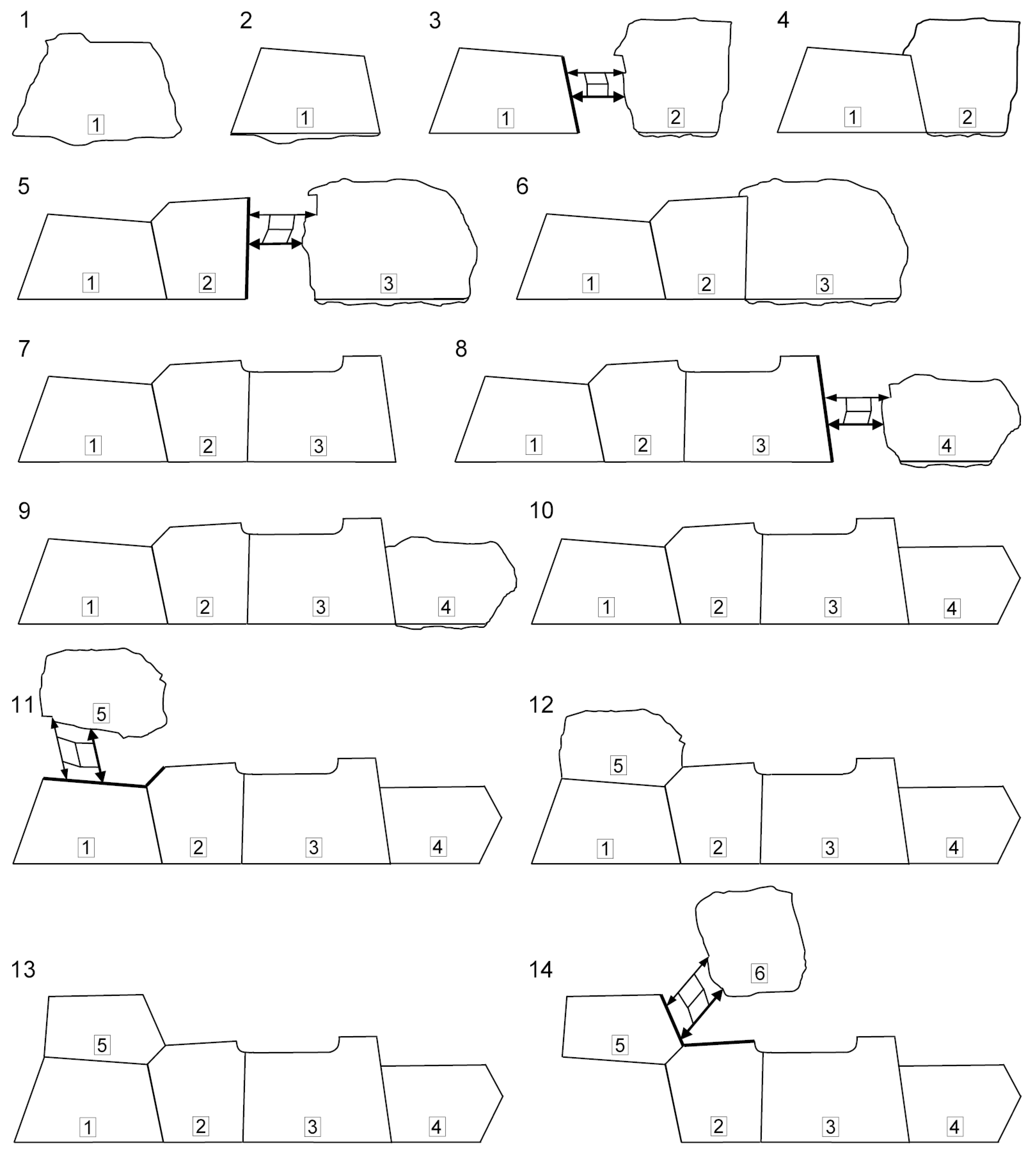
Figure 6.
Processing sequence of stone blocks using the topography translator. The polygonal masonry is represented by eight blocks laid in two courses of four blocks in each course. The sections, by which the stone blocks are mated, are shown by a bold line. Except position 22, the stone blocks lie on the ground on their backsides. The translator is shown in a simplified form. Movements of the carrying rod over the processing surface related to the exhaustion of the translator's action range are not shown. To transfer the U-shaped recesses, the bent tips are screwed in into the measuring rod instead of the straight ones. The straight-line sections of the interfaces between the blocks are only depicted as straight-line ones; actually, they are curved somewhat.
Since it is inconvenient to process the blocks lying on the ground, a trench should be dug in the ground around the block being processed, allowing a mason to work while sitting or standing. In order to significantly reduce the volume of soil being moved while providing the convenient working position of the mason, the stone blocks should be placed not on the ground, but on tables assembled from logs, sheathed with boards, and covered with a layer of chipping.
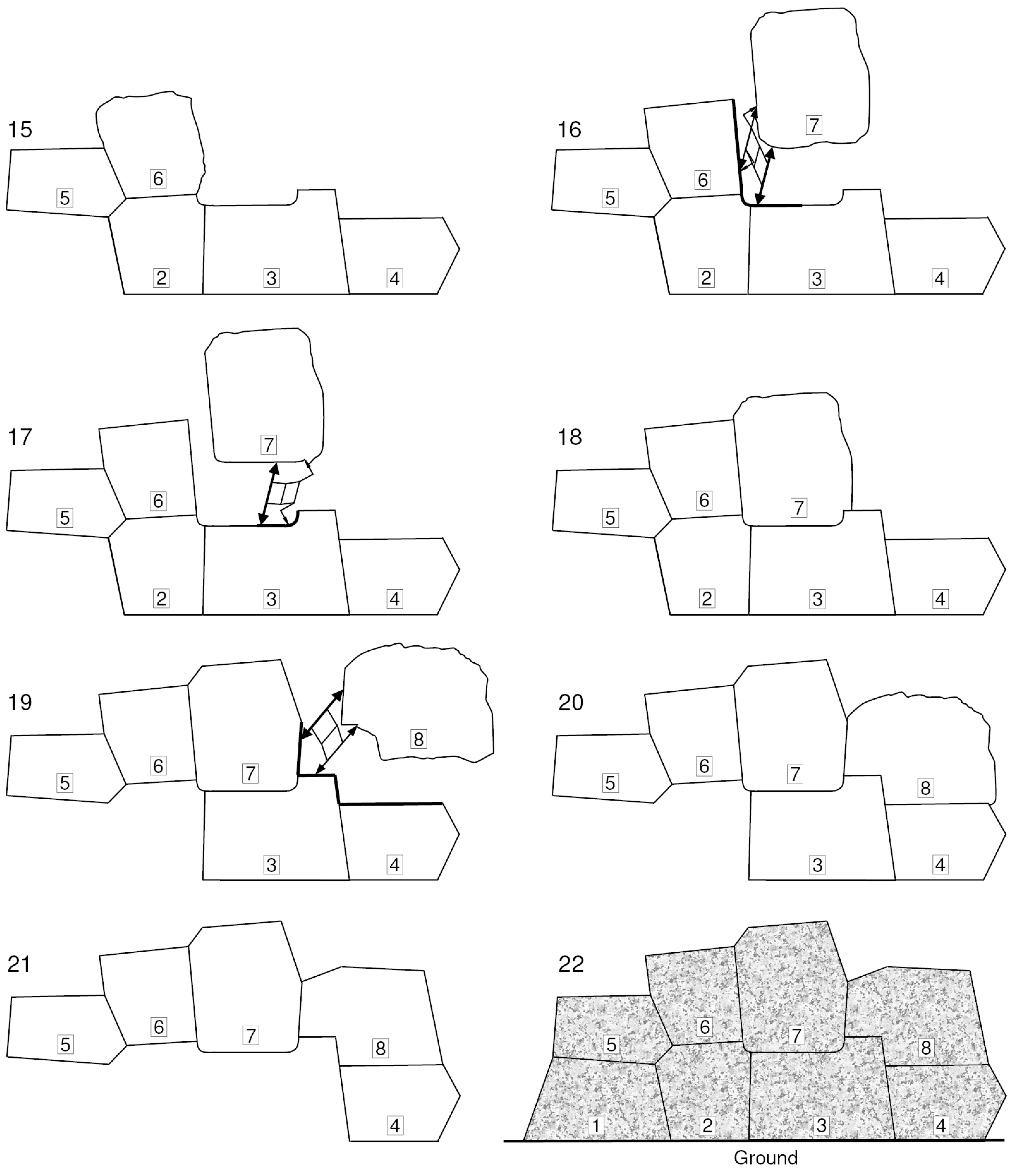
Figure 6.
Continuation.
Next, the translator is installed between the first and second blocks parallel to the base lines of these blocks. After that, the topography is transferred from the side face of the first block to the side face of the second block (the end of the copied area is shown by a bold line). If the joining side faces of the blocks are perpendicular or almost perpendicular to the block bases then the translator is installed on the flat supports; otherwise, the translator is installed on the pointed supports. If the joining side faces of the blocks are tilted to the bases at too acute angles (less than 45°), then the bent tips are screwed in into the measuring rod; otherwise – the straight tips. The translator in Figure 6 is represented in a simplified form. To avoid detail overloading of the figure, the carrying rod movements over the processed area related to the translator's range exhaustion are not shown hereinafter.
Now, the second block is joined to the first one in the horizontal position (pos 4). During joining the second and all the subsequent blocks, first of all, one monitors for accuracy of matching of the contact areas of the adjacent blocks, the minimality and constancy of the gaps. Next, on the remaining side surface of the block 2 except for the base, the rest (arbitrary) faces of this block are formed (pos. 5). As before, the processing of these faces except for the significantly curved areas in L- and U-shaped recesses (pos 7) represent rectifying of the complex initial shape of a stone billet with close to plane surfaces.
Now, along the perimeter of the front side of the second block within a certain strip, the strictly horizontal plane is fabricated exactly coinciding with the front plane of the first block. Horizontality check is carried out with the plumb level. To do this, first, one leg of the plumb level is installed on the horizontal edge of the front surface of the first block, and the other leg of the plumb level – on the processing horizontal edge of the front surface of the second block. As moving away from the edge of the first block, horizontal areas on the front surface of the second block that are ready to this moment start to be used to check horizontality.
Having completed fabrication of the horizontal area in the form of a strip going by perimeter of the front face of the second block, the beveled edge is formed (if the latter is provided for in the project). The beveled edge is fabricated along the entire perimeter with the exception of the mating section and base. The beveled edge on the mating section of the second block and on similar mating sections of all the subsequent blocks is fabricated after dismantling the horizontally lying wall before its final vertical assembly. As in the case of the first block, the beveled edge boundaries on the second and subsequent blocks are scribed on using the marking gauge. After that, a flat base of the second block is formed along the drawn line perpendicular to the plane of the front surface (pos. 5).
If the front surface of the stone blocks in the masonry should be flat according to the project, then excess stone material is removed from the front surfaces (excepting areas suitable for the pedestals/bosses formation) until an approximately flat surface is obtained. It is much easier to maintain the flatness of the wall being erected when the stone blocks have a comparatively flat front surface. The problem with the straightness and flatness of a polygonal masonry arises from the fact that such masonry does not have clearly defined courses (as in the masonry consisting of stone blocks having the same height, for example) and, consequently, its stones can not be laid along a stretched construction cord.
If, according to a project, the front surfaces of the stone blocks should have a noticeable bulge of the front surface, surface of a ragged stone, and/or a significant swell in the lower part of the block (see Section 3.1), then pedestals (leads) are fabricated on the front surfaces to hold the straightness and flatness of the wall (especially along the wall) being erected. To define the wall plane, the pedestals are made of the same height relative to the plane of the front surface. The pedestals allow checking the straightness and flatness of the wall over extended sections of the masonry in the horizontal position using a construction cord. Also, using a construction cord and a plumb line, it is possible to check the flatness of the wall in the vertical position during its erection. Some time after finishing the vertical wall assembly, a part of the pedestals are chipped off, the remaining part are converted into bosses (see Section 3.1).
The above steps are repeated for the third, fourth (pos. 5-10) and, if necessary, for the subsequent blocks of the first course. Having completed the first course construction, one proceeds to fabrication of the second course of the masonry (block 5, pos. 11).
To make the second course, a preprocessed stone of arbitrary shape slightly smaller in size than the stones of the first course is taken and also put on the ground with its backside down. The untreated front surface of the stone should again be positioned approximately horizontally (pos. 11). The stone block 5 is put next to the first block of the first course to join them. The translator is installed between the blocks and topography is transferred from the top face of the first block and from a small area in the upper part of the side face of the second block to the bottom face and a small area in the lower part of the side face of the fifth block.
Unlike the blocks of the first course, where the joining of the adjacent stones took place over one side section usually, the blocks of the second and the subsequent courses are joined over more than one section. As a rule, the joining of these blocks is carried out over the base and the lateral side adjacent to the base (pos. 11). If the angle between the neighboring sections being copied is close to 180° then the translator is installed on the flat supports. Otherwise, the translator is installed on the pointed supports.
The block to be fitted should be located relative to the masonry so that the amount of stone material removed is minimal. The translator should be installed on the pointed supports so that it is tilted approximately equally to both sections being copied. If the angle between two copied sections is too sharp (less than 45°) then the bent tips are screwed in into the measuring rod, otherwise – the straight tips. If the bent tip is unable to penetrate into a sharp interior corner then such angle should be replaced in the masonry by a rounding of suitable radius.
Having completed the transfer of topography in the interface area, the fifth block is jointed to the first and second blocks (pos. 12). Then, the rest (arbitrary) faces are formed on the remaining side surface of block 5 (pos. 13). After that, a strictly horizontal plane exactly coinciding with the front planes of the first and second blocks is fabricated along the perimeter of the front side of block 5 within some strip.
The horizontality check is carried out by means of the plumb level. To do this, first, one leg of the plumb level is put on the horizontal edge of the front surface of the first block, and the other leg of the plumb level – on the horizontal edge of the front surface of the fifth block being processed. As moving away from the edge of the first block, the horizontal edge of the second block starts to be used to check horizontality. Finally, moving away from the edge of the second block, the horizontal sections ready by this moment on the front surface of the fifth block start to be used to check horizontality. Having finished the fabrication of the horizontal edge of the front face, the beveled edge is formed (if it is provided for) on the remaining sections of the fifth block excepting for the reciprocal part of the interface area.
If there are suitable height stone excesses on the front surface of a block in locations convenient for placing pedestals, then the pedestals of the set height are fabricated in these locations. Using the new pedestals of the current block and the pedestals made earlier on other blocks, one checks the straightness and flatness of the current block in the masonry applying the construction cords. In case of deviation from the straightness and flatness, one adjusts the current block position correspondingly, while trying to keep the smallest gaps and their constancy.
Note that the interface sections between the blocks in Figure 6 are just shown as rectilinear. In practice, all these sections are curvilinear to greater or lesser extent. Having finished the block 5 processing and checking its face surface matching with the wall plane (pos. 13), block 1 can be removed from the temporary masonry (pos. 14) and passed for the final wall assembly (pos. 22). Block 1 and others like it can be removed from the temporary masonry and passed to the final wall assembly, if the block does not participate in the flatness check (does not have pedestals) or its removal will no longer significantly affect the detection of deviations from the wall flatness of the current and subsequent blocks. The processing of block 6 is similar to the processing of block 5 (pos. 14-16).
Processing of block 7 for the U-shaped recess consists of two steps. First, the lateral side of block 6 and an approximately half of the U-shaped recess in the blocks 2 and 3 are copied, which is the first (direct) L-shaped recess (pos. 16). Then, the copying of the U-shaped recess continues on the second (counter) L-shaped recess (pos. 17). Copying of the direct L-recess (pos. 16) can be performed by both the straight tips and the bent tips (in Figure 6, both types of the tips are shown together for clarity). Copying of the counter L-recess (pos. 17) is performed using the bent tips. Note that during the transfer of the direct and counter L-shaped recesses, the translator orientation in space should remain unchanged.
If the straight tips were initially screwed in into the measuring rod while transferring the U-shaped recess then they should be replaced with the bent ones at the second step (the assigned distance between the ends of the probe and pointer should not be changed). If the bent tips were initially screwed in into the measuring rod while transferring the U-shaped recess then at the second step they should be turned by 180° by screwing in the probe and screwing out the pointer (or, vice versa, by screwing out the probe and screwing in the pointer).
In the case of a large number of acute angles and U-shaped recesses in the masonry, it is convenient to use the topography translator whose measuring rod has cylindrical hinges providing free rotation of the measuring rod around its own axis (see Figure 5b). The adjustment of the position of the bent tips of the measuring rod for operation on the first and second L-shaped recesses is actually reduced to revolution of the measuring rod around its axis by an angle suitable for the given location.
Having installed block 7 at its place (see Figure 6, pos. 18), the remaining side surface of this block is subjected to the arbitrary processing (pos. 19). Having completed block 7, block 2 can be removed from the temporary masonry (pos. 19) and moved to the polygonal wall construction site for its final installation (pos. 22). If a block of the previous course is unextractable or hardly extractable at the current stage of the block fitting then this block can be extracted later, when its retaining blocks will be completed. The main restriction on removing a finished block from an unfinished masonry is the presence of pedestals on it involved in flatness checking of the wall being created. Fitting of block 8 (pos. 19-21) is clear from the figure. If necessary, the third and subsequent courses of the polygonal masonry are fabricated similarly to the fabrication of the second course of the masonry.
Having completed the trial assembly of the wall of polygonal blocks in the horizontal position, the wall is disassembled. On the reciprocal sections of the interfaces of the extracted blocks, the beveled edges (if they are provided for by the project) are completed according to the accepted way. After that, the wall is finally assembled on a prepared site.
The final appearance of the wall consisting of eight blocks laid in two courses is shown in the figure, pos. 22. Although the obtained masonry contains a keystone (block 7), the assembly, for example, of the second course of such masonry does not necessarily have to be completed by installing this stone at its position. As one can see, the wall assembly can be carried out sequentially in the order of fitting of the stones. The base planes of the stone blocks of the first course can be fabricated at an angle slightly less than the right angle to give the wall a slight slope. Processing of the backsides of the stone blocks of a bearing wall is carried out after its assembling. The backside of a retaining wall is not processed in any way.
Some time after wall erection, the size and constancy of the gaps as well as verticality (a set slope) and flatness of the wall are checked. Verticality and flatness are checked using the plumb line and construction cord. If the specified wall characteristics are within the acceptable values, some of the pedestals are removed from the front surface according to appropriate aesthetic criteria and appearance of the remaining ones is modified to the required style turning them into bosses (see details in Section 3.1).
Instead of the pedestals or together with the pedestals, pyramids of the same height can be used, which tops define the position of the horizontal plane parallel to the horizontal plane of the front face[22,62]. Most of the pyramids are put on the horizontal areas along the block edges. For some blocks approximately in the center of the front faces, it is possible to make recesses, whose bottoms coincide with the horizontal plane of the front face. During the trial assembly of the wall in the horizontal position, the pyramids are simply installed along the edges of the blocks on the horizontal areas and put in the recesses. By applying the construction cords to the tops of the pyramids and/or installing straight verifying bars on the pyramid tops, it is possible to determine the coincidence acceptability of the front planes of the stone blocks with the wall plane.
To check the flatness of the polygonal masonry during the vertical wall assembly, the pyramids should be somehow secured to the edges of the blocks and in the specified recesses. If the recesses are deep enough, the pyramids can be fixed in the recesses with wedging eccentrics or with wooden wedges in the simplest case. Since the recesses for these pyramids spoil the appearance of the polygonal masonry, their use was most likely limited to the masonry whose final appearance of the front surface represented a plane or ragged stone. In the latter case, the recesses were simply chipped off some time after wall erection.
While interfacing, the corner blocks connecting walls, say, at 90° angle are laid on the ground generally in the same way as the conventional blocks. One should only ensure the horizontal position of the plane of the corresponding front face of the corner block and its coincidence with the plane of the wall being made. To do this, a recess of a suitable shape and depth is excavated for the corner block in the ground. Corner block fixation on the ground is carried out in the same way as the regular one – with the help of the wedging stones. After mating the blocks of the first wall, alignment marks are applied to the corner blocks with paint; after that the stone blocks, excepting for the corner blocks, are sent to the final assembly site.
Further, the fitting of the blocks of the second wall starts from the first lowest corner block, which is rotated by 90° so that the second front face of this block looks up now. After that, the first block of the second wall is mated to this corner block as described above. Next, as the blocks of the second and subsequent courses of the second wall are mated, the corner blocks are joined to each other according to the alignment marks.
Thus, when using the topography translator, walls with corner blocks are erected sequentially by separate sections bounded on the left and right by the corner blocks. When using a 3D-pantograph, the mentioned restriction is absent, since the processing of ordinary blocks and corner blocks is carried out according to the models and does not require an intermediate placement of the stone blocks on the ground and their mating in the horizontal position during fabrication (Hatunrumiyoc Street in Cusco, Ollantaytambo). In the case of the 3D-pantograph usage, the final assembly of the walls with corner blocks is performed sequentially course after course taking into account the lock blocks in the course, if any.
Applying the topography translator, it is also possible to erect walls of two (or more) blocks thick by interfacing the block backsides of the outer wall with the mating surface of the second (inner) wall. To do this, both the walls are made in the way described above. The outer wall is assembled finally and its backside is arbitrary processed, forming the conditionally flat sections. After that, a second (inner) wall is temporarily assembled at some distance from the first wall parallel to it. The distance between the walls is set so that a stonemason can fit in the space between them and work with the hammer and chisel without much constraint. Next, the topography translator is installed between the walls as a strut; after that, the topography is transferred from the backside of the first wall to the mating surface of the second wall. Having finished the mating, the second wall is reassembled right next to the first one.
Depending on terrain peculiarities and requirements related to the structure, the order of wall joining can be changed, i.e., first, the second (inner wall) is finally assembled, and then the first (outer) wall is joined to it in the above way. When the terrain peculiarities do not allow for the specified fitting of the walls, or the walls include shared blocks, or blocks of the walls are strongly bonded [8] between each other in the transverse direction, the polygonal masonry is made by using the clay models and 3D-pantograph; and the assembly of the wall of two or more block thick is finally carried out at the planned location course upon course. It seems that this is how the Temple of Ten Niches in Ollantaytambo was fabricated (see Photos 11 and 12), which wall has two block thickness.
2.11.4. Specifics of the topography translator application
The operation of the proposed device is based on the well-known principle of conjugation of two surfaces. In one-dimensional version, this principle is implemented in a marking tool like the marking gauge [59]. Article [7] presents a one-dimensional version of the principle of fitting of stone blocks close to parallelepiped shape. In article 14, a two-dimensional version of the principle of conjugation of stone blocks is taken as a basis of the method of polygonal masonry fabrication. In contrast to the method described in article 14, the operation position of the topography translator in space in the method under consideration is exactly defined and due to the double parallelogram mechanism can be arbitrary.
In practice, the most convenient positions of the translator are close to the horizontal position as they allow the stonemason to process vertically located mating surfaces of stone blocks lying on the ground opposite to each other backside down. The front surface of a stone block is located horizontally and is fully accessible for processing also. Moreover, the blocks fitted according to the proposed method can be joined in this position with each other (adding chipping and inserting small wedging stones) that allows us to check the quality of the implemented interfaces before putting the blocks into a wall.
Unlike the 3D-pantograph, the topography translator allows to immediately correct accidental stone chips at the interface of stone blocks by copying the chipped area back on the original surface using the pointer as a probe and the probe as a pointer. When using a pantograph, to correct accidental chipping, one needs to make corrections in the mating faces of two adjacent clay model blocks.
In method 14, due to referencing the measuring rod to the vertical direction by means of a plumb line, in order to process the upper side of the block of the previous course the stonemason has to put the block of the current course, by which base the fitting is performed, above the block of the previous course that is unsafe and requires a lot of additional efforts. In particular, it is necessary to provide stops (recesses or protrusions) on the stone blocks, fabricate logs-stops, bury these logs-stops into the ground, put the stone blocks on the logs-stops at the beginning of the work, and take down the stone blocks from the logs-stops after finishing the work.
In addition, it should be possible to change position of the current block located on the support logs in order to align it in the vertical plane by the plumb line and in the horizontal plane by the construction cord. Meanwhile, platforms, scaffolds, ramps, etc. are required to access the conjugation surface being processed from the front side of the wall and to access the front side itself. Moreover, the use of the plumb line in method 14 significantly reduces stonemason productivity, as a lot of time is required to settle the plumb line during the surface treatment of the block. In addition, the use of the plumb line itself can be very difficult in the event of a strong wind.
Yet another disadvantage of method 14 is that the measuring rod, unlike the topography translator, is not fixed in the space completely. As a result, during the processing of the stone blocks, unintentional rotations of the rod around its vertical axis by small angles ±∆α will occur inevitably. The larger is the angle of rotation ∆α and the longer is the rod length l, the larger is the error ∆l related to such rotations.
Let us assume for simplicity that the measuring rod is initially located normally to two parallel flat areas of the processed stone blocks. Then the error caused by the random rotation of the rod can be estimated by the following simple formula: ∆l=l⋅(1/cos ∆α-1). Thus, for the measuring rod of even a moderate length, say, l=70 cm, we find that the error ∆l in method 14 will already exceed 5 mm for the rod deviation just by angle of ∆α=7° from the correct starting position.
Vincent Lee, the author of article 14, initially proceeded from the fact that the polygonal masonry in the Peruvian megalithic structures was created by the Indians. In accordance with this initial assumption, Vincent Lee had to use a plumb line as the simplest measuring tool that could be known to the Indians at that time. Moreover, in the method he suggested, Vincent Lee wanted to use the protrusions (bosses) and recesses on the front sides of the stone blocks of the Sacsayhuaman Fortress in some way for creating the polygonal masonry. Hence, an extremely costly in terms of the applied efforts and dangerous arrangement of the processed stone blocks one above the other arose.
In the method proposed here, the parallel movement of the measuring rod is not connected with the normal to the Earth's surface in any way and can occur at any orientation of the translator. Therefore, the fitting of the blocks and their pre-assembly are performed when the blocks lie on the ground with their backsides down. Hence, as in the case of the 3D-pantograph application, a sign of the usage of the block fitting method will be the same tilt of the chisel marks on the mating faces of the stone blocks to the direction which is perpendicular to the front surface. Only after completing the joining of the blocks of the current course on the ground in the horizontal position, the blocks of the previous course can finally be installed at their places in the wall under construction. Therefore, in the proposed method, there is no need to process the stones on the wall being erected in the cramped conditions and at the risk of life.
Topography transfer of the adjacent sections with a sharp boundary and with a smooth boundary (for example, in the form of L- or U-shaped recesses) is performed in a single operation. This means that the orientation in space of the carrying/measuring rod and the distance between the probe tip and the pointer tip of the measuring rod remain unchanged at both sections all the time. While passing to the section of the counter L-recess while transferring the U-shaped recesses, it is necessary to replace the straight tips of the measuring rod with the bent ones or to turn the bent tips by 180°, if they were used initially.
During the topography transfer, the translator is often located at angles to the joined surfaces which are different from the normal significantly (see Figure 6). Such translator orientation in the case of the sufficiently sharp probe and pointer causes just an insignificant additional error of the topography transfer. The greater is the deviation from the normal and the larger is the radius of curvature of the probe and pointer tips, the larger is the value of this error. The bent probe and the bent pointer are intended for the cases when the straight probe is under a small angle to the surface to be copied.
The block fitting method described in the present paper could be used for construction of walls with comparatively simple polygonal masonry, where the mating surface areas have a small curvature, there are no figured cusps or sharp steps at the triple junctions (there is no “feeling of modeling”, see the next section). Since in the method under consideration, the sequential fitting of the blocks in-place is performed, the sign of this method usage will be the mounting of large blocks in the first course of masonry directly on a strengthened soil or on a pre-prepared bedrock, i. e., without the small “alignment” blocks in the first course of the masonry that ensure the correct mutual position of the large blocks of the second and subsequent courses (see more details in Section 2.1). If we see that, according to all signs, the method of block fitting in-place was used, but the large masonry blocks lie on small blocks, then this means that the masonry was once reassembled and may have been moved here from another place. Moreover, the reassembly and/or move were performed much later than the time of the initial structure erection. The masonry quality loss after its reassembly is associated with the destruction/monolithing of contact areas (see Section 3.3), the absence of part of the pedestals, and possibly with insufficient qualification of those who carried out this reassembly.
One more sign of the topography translator usage will be the small paired recesses located strictly opposite to each other (the larger the area of the mating surface, the greater the number of these recesses). The recesses are made at the locations where the carrying rod of the translator is installed on the pointed supports at angle to the mating surfaces. The presence of a set of low-contrast annular regions superimposed on each other on one of the mated surfaces can also serve as a sign of the use of the proposed above topography translator. One more sign of the translator usage is the presence of a “visor”, which often occurs during the block fitting (see Figure 6, pos. 4, block 2; pos. 6, block 3; pos. 18, block 7; pos. 20, block 8). Sometimes, such visors are found on unfinished blocks, being, in turn, a sign of the block unfinisheness. [63]
It should be noted in conclusion that the main advantage of the proposed method is that half of the mating surfaces of the stone blocks are processed arbitrarily.
3. Polygonal masonry peculiarities, questions related to dating and authorship, economical grounds
3.1. A general bulge of the front side and a swell in its lower part, bosses, cusps/steps at the triple junctions, polygonal bas-relief facing
A typical general bulge of the front surface as well as a swell in its lower part (should not be confused with bosses) found in some structures (see, for instance, Photos 2–6) often serve as one of the proofs of the “plastic” version [18,19,20,21] of the polygonal masonry fabrication. According to the plastic version, the partially solidified blocks were stacked one on another. As a result, the interblock gaps in the polygonal masonry were closed under own weights of these blocks and the front surface got the specified bulge and swell.
In the proposed method, both signs – the bulge and the swell can appear by themselves at the stage of fabrication of the clay model of the wall unless the clay mixture was not thick enough and no sheathing was used on the front side. The bulge and the swell can also be produced intentionally while sculpturing the clay model.
Most likely, the bulge and swell were given to the blocks intentionally. Both features increase the feeling of massiveness, grandiosity of the structure, its colossal weight; it seems to us as if the stones are flattened under a huge weight. The bulge was also intended to demonstrate to the naive Indians the power of the arrived whites, who could “sculpt”, if necessary, a building out of huge hard stones as if from dough.
The bosses (see Photos 2–11, 15, 16) are a well-known architectural decoration. [64] The polygonal masonries having no bosses and no bevels along with the absence of other architectural elements (arches, cornices, etc.) would look dull and monotonous especially in the cases when the block shape is close to a parallelepiped. They would look like a wall decorated with identical plane ceramic tiles. The role of the bosses as an architectural decoration in the polygonal masonry under consideration, where the blocks have an intricate geometric shape, is less significant. The fact is that the task of acquiring an attractive, interesting appearance and diversity is solved in such masonry due to the bizarre shape of the polygonal blocks themselves. Besides the architectural decoration, the bosses serve as a kind of a signature of the group of the professional builders (see Section 3.5) who created the structures in Peru and similar ones around the world.
The bosses, whose sizes, shape, and location obey no any strict regularity from block to block, were crafted on stone blocks of arbitrary shape when there was simply an excess material of required sizes at a suitable place on the front side. In the stone blocks which bosses possess a regularity, to craft these bosses, a layer of material is removed from the front surface. Such bosses usually just slightly protrude outside, because the more the boss protrudes, the thicker is the layer of the material that must be removed from the front side. Initially, a part of the bosses could serve as the pedestals (see Section 2.11.3) used to keep blocks within the same plane at extended sections of the polygonal masonry.
Bosses are located on the front side of the block solely and are never found on the backside. This fact excludes hooking on these block protrusions by loops of hoisting slings. The shape of many blocks in the polygonal masonry under consideration is very different from the shape of parallelepiped. Such blocks cannot be safely lifted by passing the hoisting slings underneath. In addition, the hoisting slings can damage fragile elements of the stone blocks such as cusps and steps (see below). Passing the hoisting slings under the block results in the inconvenience of their extraction from under the block after installing the block on its position in the polygonal masonry.
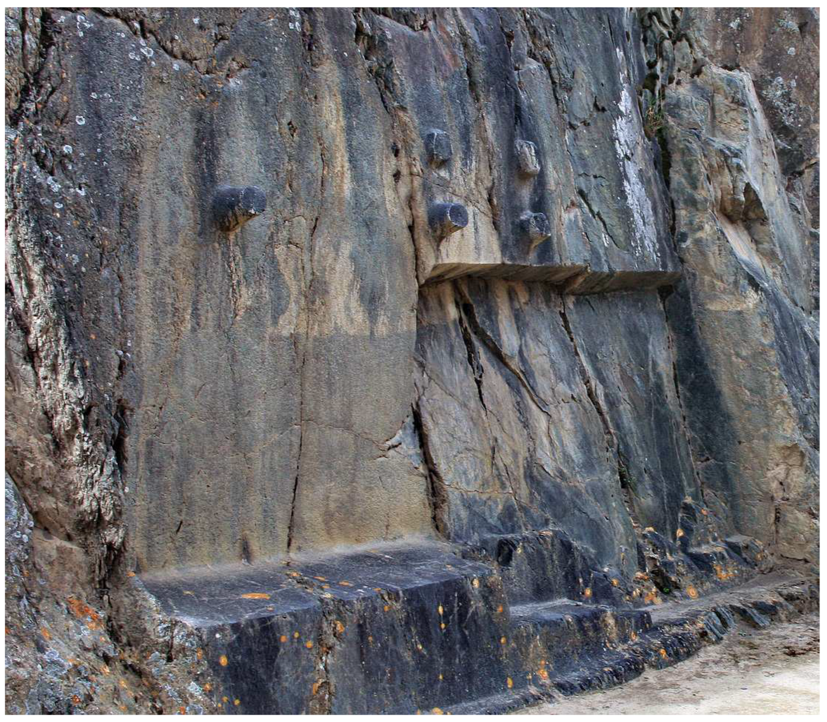
Photo 18.
Bosses on rocks in Ollantaytambo (E. Berzin, 2015, allenatore.livejournal.com). The sites like that is a sort of near road Christian chapel familiar to us, a place of “power”, a holy spring, a memorable place or a kind of monument in honor of some hero or event.
Photo 18.
Bosses on rocks in Ollantaytambo (E. Berzin, 2015, allenatore.livejournal.com). The sites like that is a sort of near road Christian chapel familiar to us, a place of “power”, a holy spring, a memorable place or a kind of monument in honor of some hero or event.
Of course, the slings can be extracted from under some of the blocks, but in general, the procedure turns out to be quite laborious and unsafe. To extract the slings, the current block is first put on wooden bars (or on a single wide bar under the gravity center of the block) at a short distance from the previous block of the masonry. A restraint wooden bar (stop) is inserted between the previous and current blocks. Then, they take out one sling (that is closer to the previous masonry block) and, lifting the block with another sling, tilt the block (put on the edge) so that one can remove the bars located under it. Now, a wooden bar in the form of a wedge is placed under the raised edge of the block and the block is lowered on it. The last sling is extracted. The restraint bar is removed and the current block is moved down along the wedge close to the previous block.
Note that the specified installation of the block on the edge for many blocks in the polygonal masonry under consideration is difficult or impossible simply because of the geometry of the blocks used, and it is impossible in the case of the last key block in the masonry course in principle. Moreover, when installing the block on the edge and during its final move, the stone will crumble at point contacts and such elements of the block as edges, cusps and steps (see below) will highly likely be damaged or destroyed.
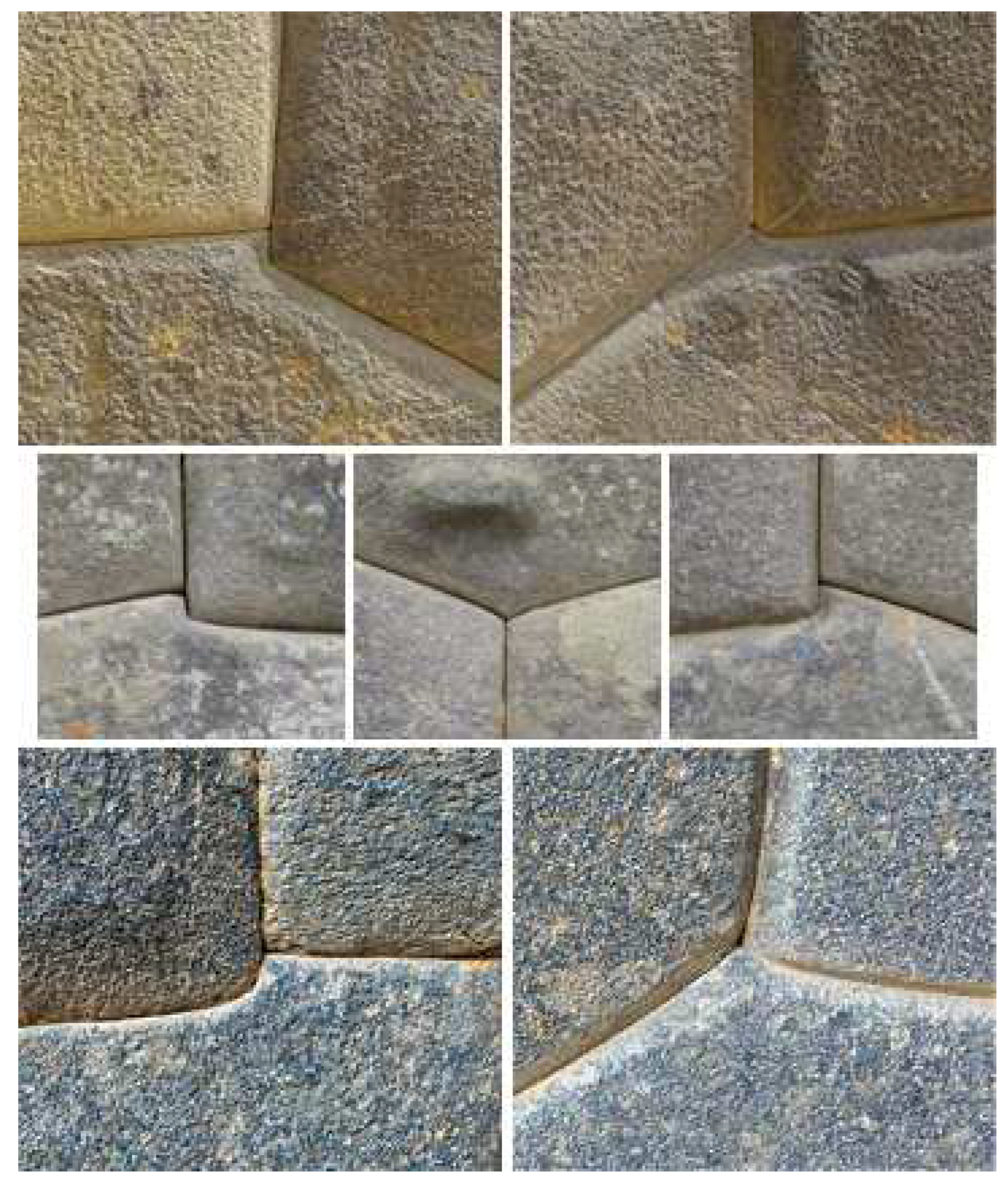
Figure 7.
Cusps and steps.
The hoisting slings can be used to hook stone blocks, whose front side is located horizontally. For example, the hoisting slings can be used to lift and move blocks during their mating by means of the topography translator and subsequent joining in the horizontal plane. In this case, the manipulated blocks rest on the ground of fine crushed stone, which makes it easy to thread the slings under the block edges before lifting and moving, and to extract them back after the lifting and moving.
Numerous medieval drawings and engravings (see, for example, Ill 1) show clearly that the builders of those years used a self-holding mechanism – block tongs [43,45] (lever-type lifting tongs31) to hold the stone blocks during lift-and-carry motions. Of course, the tongs and the block lifted with it are shown in the picture schematically enough, just to demonstrate the principle. In practice, more complex devices can be used in those days. For example, 2-3 tongs located in parallel on a common traverse could be used to lift and securely hold a heavy block. In addition, the tips of the tongs could be connected by beams parallel to the traverse for ease of operation and greater reliability of load retention, etc. In the case of a danger of block slipping out, recesses were made on the untreated area of the front side and on the backside of the stone block for better claw engagement of the hoisting mechanism. [65]
Given that there are no bosses on the backside, there is usually ragged stone there, the use of bosses to hook the claws is somehow justified only in the case when there is a couple of bosses and they are located near block edges on the left and on the right approximately along the same horizontal line in the upper part of the block (or there is a single boss located exactly in the gravity center in the upper part of the block) and the tips of the claws are connected by means of the above-mentioned beams. However, in fact, we see that the bosses are rarely located in a line near block edges on the left and on the right in the upper part of it and are most often concentrated in the lower part of the block.
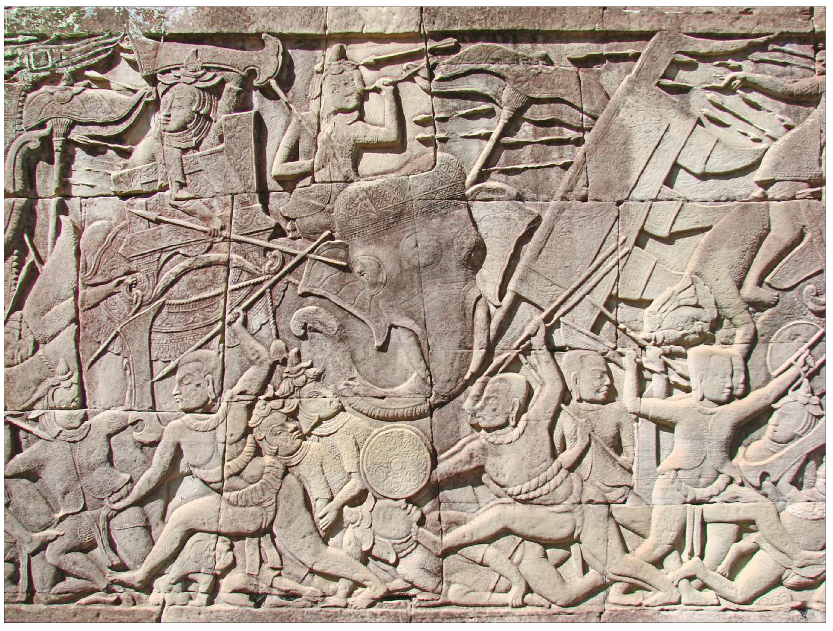
Photo 19.
A fragment of a bas-relief on the front surface of the polygonal masonry of the Angkor temple complex, Cambodia (J.-P. Dalbéra, 2011, www.flickr.com/photos/dalbera).
Photo 19.
A fragment of a bas-relief on the front surface of the polygonal masonry of the Angkor temple complex, Cambodia (J.-P. Dalbéra, 2011, www.flickr.com/photos/dalbera).
In general, when using the existing bosses for a hook, it is impossible to ensure reliable retention of the block due to a chance of its overturning and/or the boss splitting off. Since hoisting slings are not required while using the block tongs, no protrusions, recesses, or grooves need to be made on the stone block to hook/pass these slings. Thus, no bosses are needed to lift, move, and install both the stone billets and finished blocks.
The bosses on rocks (see Photo 18) are not bridges left after block separation from the rock massif in a quarry during stone extraction. Firstly, these bridges look too neat for auxiliary elements representing a side result of the cutting down process. Secondly, these bridges are so few that they can hardly be attributed to some systematic technique of stone extraction. Thirdly, the labor productivity of the implied method of the cutting down is close to zero.
Moreover, the type of the polygonal masonry under consideration, as already noted (see Section 1.2), uses boulders and stone blocks of arbitrary shape as building material. These boulders and blocks are fragmental material of natural origin. Thus, the boulders and blocks did not need to be broken out in quarries in most cases, especially in such exotic way. A place in the mountains with bosses deliberately carved on a rock is something like a Christian chapel at a parting of the ways familiar to us, a place of “power”, a holy spring, a memorable place or a kind of monument in honor of some hero or event.
The cusps (“beaks”) and steps (see Figure 7) are clearly visible in the points where three adjacent blocks meet. These elements are produced while sculpturing the clay model and then transferred on the stone block with the pantograph. Besides the stop limiting movement of the adjacent block in the horizontal plane, the cusps/steps give the polygonal masonry a special grace. According to the creators’ idea, the cusps along with the parallelism of the smoothly changing curved edges were intended to give a sense of easiness of working with a large and heavy stone. These features make the viewer think that the blocks are literally sculpted of stone. We must pay a tribute to the old masters; they succeeded in this technique!
Given the above, instead of the term “polygonal masonry”, it would be quite fair to use the term “polygonal sculpture” in the cases when a stone structure is created on the basis of hand-sculpting of a clay model made in a certain artistic style with unique lock interfaces between blocks. Besides the simple dressing of the front side of the stone blocks, the proposed technology allows to create a polygonal masonry which face surface is a bas-relief. The temple complex Angkor56 is the example (see Photo 19), where such facing technology may have been applied. If the presented bas-relief had been made in a layer of plaster we would not have seen the joints between the polygonal blocks.
3.2. Indirect dating by the observed destructions of the masonry elements
The cusp is one of the weak points of the polygonal masonry in terms of strength. Thus, the cusps should fail during the natural weathering process [22] first of all. Many stones in Peru are covered with a lichen (see Photos 7–10), so the biological factor must also be taken into account in addition to the weathering when estimating the rate of the stone destruction. Surprisingly, the type of the polygonal masonry under consideration is perfectly preserved in the mountains (Cusco, Machu Picchu, Ollantaytambo, etc.), where the climate is characterized by sharp temperature changes 15-20 °C during a day, by a lot of precipitation and by light frosts in winter (June-August). [66].
Besides weathering, a shift of stones in the masonry during an earthquake or during a landslide move of the slope (often triggered by an earthquake) can cause destruction of the cusps [3,4,5]. It should be noted that the cusp cleavages could occur while processing the stone block, during transportation, installation, or restoration. Some of these cleft cusps can be partially repaired. The repaired cusps will look more sunk into the body of the masonry than the normal ones.
The study of the polygonal masonry from hard rocks [22] (granite, andesite, diorite, basalt) shows that the cusp damages are present but they are few in number. The absence of noticeable destructions under the fairly harsh climatic conditions and high seismic activity in Peru give a reason to assert the rather recent, for about 300 years, construction of the megalithic complexes. A rough estimate can be obtained by comparing the state of the megalithic complexes with monuments being in similar weather-climatic conditions, made of similar materials, and whose date of construction is known for certain.
3.3. How to prove it? What should we look for and where?
What can serve as a confirmation of the proposed methods of fabrication of the polygonal masonry? On the territory or near the complexes with the polygonal masonry or in quarries, construction debris should remain, in which fragments of clay model blocks and fragments of clay/gypsum replicas should be searched for. Certainly, first of all, we need to study the materials of the conducted excavations. It is not unlikely that some suitable fragments in shape, size, and materials have already been found and documented. Most likely, much of the debris was used for strengthening the ground under the next erecting structure nearby. Therefore, in the case of reassembling some polygonal structure damaged by natural forces, the evidences in the form of the clay models and replicas should be sought in the ground under the structure itself.
Assuming that in the pantograph used by the builders, the clay model and the stone billet were positioned in the same way as in the modern pantograph, i.e., horizontally with the backside down (to fix the block in case of uneven back surface, small wedging stones are used), then the chisel marks on the side surface of the stone blocks should go from right to left (chisel in the left hand, hammer in the right) and from top to bottom (the recess is larger at the beginning of the trace than at the end). The marks themselves should be short parallel strokes arranged in vertical columns.
The chisel marks should be searched for on the stone blocks from hard rocks – granite, andesite, diorite, basalt. Soft rocks [22], such as tuff, limestone or sandstone have a high porosity; the surface layer of these stones is quickly destroyed by weathering. Moreover, the chisel marks on the limestone surface are easily destroyed during the subsequent smoothing operation by tapping. Because of weathering, there is also no sense to study the interface surfaces of the stone blocks from hard rocks that have lain in the open air outside masonry for an unknown number of years. To analyze an interface surface, one should take stones from some untouched masonry having minimal gaps, which could get a very small amount of moisture.
It should be noted that the several hundred years old masonry of stone blocks is most likely impossible to disassemble in such a way, so as to keep the near-surface layer of stone intact in the contact areas. The fact is that during the entire period of the masonry existence under the above-mentioned climatic conditions, various physico-chemical processes took place in the contact areas causing a change in the mineral composition in these areas [22]. As a result, depending on the process, the contact is breaking down (with sand formation) in some areas and, on the contrary, growing over and strengthening (monolithing) in other areas. An attempt to separate the areas, where the overgrowing-strengthening has taken place, will result in the destruction of the stone near-surface layer adjacent to the contact. Anyway, the sizes of the stones and their geometry will change after disassembling the old polygonal masonry. Therefore, it is impossible to reassemble the old masonry so that there would be the former tiny gaps between the blocks.
It is also impossible to nicely reassemble the old polygonal masonry, because the bosses can no longer serve as reference points for keeping the wall flatness, since some of them are simply removed after the final assembly, and the shape and sizes of the remaining ones are changed in accordance with certain aesthetic rules. In addition, there is also the destruction of the bosses due to weathering. Thus, if restorers need to reassemble an old polygonal masonry, then before starting its disassembly, they should provide for a system of leads, alignment marks, and reference points.
The noncontact method of the optical 3D-profilometry (interference microscopy) [67] is well suited for detecting the suspected marks of the mechanical processing on the surface of the stone blocks. The method allows to obtain a microrelief of the surface, and then to perform its computer analysis. The computer analysis using special programs of surface image filtering and processing helps to show more clearly and in some cases even reveal low-contrast chisel marks destroyed by tapping and weathering (modification) of the stone surface.
In particular, it is possible to determine the Fourier spectrum of spatial frequencies of the measured microrelief of the stone block surface, and then compare this spectrum with the Fourier spectra of a test surface processed with several types of chisels according to the techniques described in the article. If a stationary profilometer is used to measure the microrelief, then it is necessary to make a replica of the surface from gypsum or silicone. In the case of using a portable profilometer, the process is simplified, since the instrument is installed on the measured surface directly.
3.4. Indirect dating by the invention time of the 2D- and 3D-pantographs
If we accept the proposed methods of the polygonal masonry fabrication, the structures of “incredibly” ancient Incas can be approximately dated by the years of invention/building of pantographs by Europeans. The pantograph for working with a flat drawing was invented in 1603-1605 by Christoph Scheiner. [68] Notably, the author has published the information about the device design in the form of a separate book [69] only 28 years (!) after the invention.
Comparison of the topography translator with the 2D-pantograph shows that these devices are similar in terms of their mechanical complexity, operation accuracy, used materials, and fabrication technology. This implies that the topography translator could well have been invented and built in the early 17th century. The topography translator could have appeared even earlier, since it is functionally simpler – it does not need to solve the problem of proportional scaling.
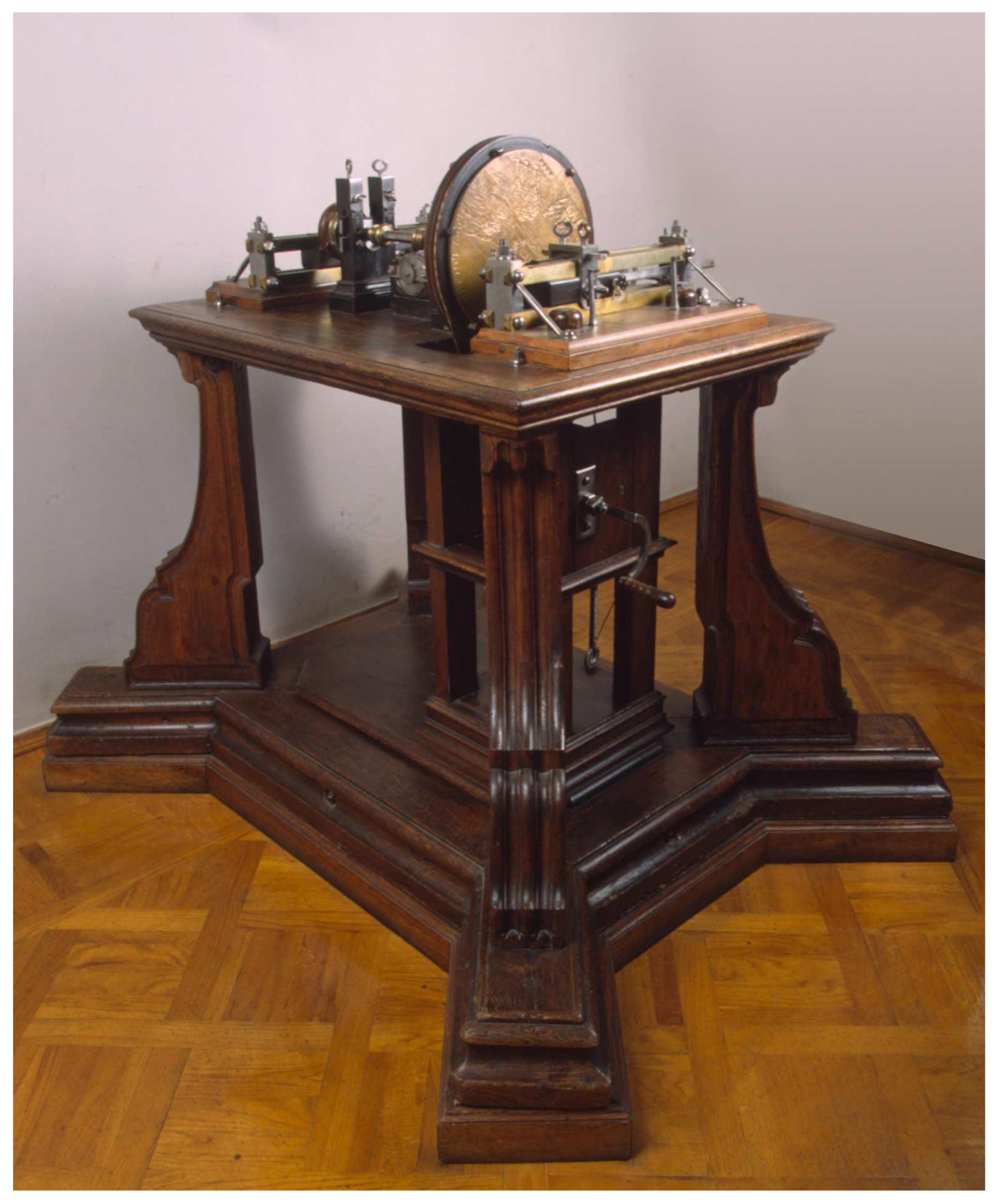
Photo 20.
The medal copying lathe by F. Singer and A. Nartov, circa 1710. The machine is intended for medal production by a large size model in automatic mode. (State Hermitage Museum, St Petersburg, www.hermitagemuseum.org).
Photo 20.
The medal copying lathe by F. Singer and A. Nartov, circa 1710. The machine is intended for medal production by a large size model in automatic mode. (State Hermitage Museum, St Petersburg, www.hermitagemuseum.org).
Around 1710-1720, Russian mechanics Franz Singer and Andrey Nartov [70] built a turning machine for medal copying (see Photo 20). [71,72] The machine was intended for production of medals in automatic mode by transferring a relief from a large size medal model. It is not quite correct to compare the Singer-Nartov machine with the modern 3D-pantograph used by sculptors (see Figure 2), since the kinematic diagrams of these mechanisms differ greatly. Despite this, attention should be paid to the complexity of the machine mechanism, which notably exceeds the complexity of the modern pantograph mechanism. In particular, the probe movement over the model surface and the cutting tool application to the billet surface in the 3D-pantograph are carried out by the sculptor manually, whereas these functions are implemented in the given example of the machine without a human intervention. Note that copying machines like this one were built and used in many European countries in the 18th century.
In 1807, James Watt [73] began to design a mechanism [74] (see Photo 21) intended for production of reduced copies of sculptures. [75] The kinematic diagram of the Watt's mechanism is close to the kinematic diagram of the modern 3D-pantograph. However, there are a number of differences. Instead of the ball joint, the boom is mounted on a universal joint; the parallelogram mechanism is missing; the model and its reduced copy are located horizontally, etc. In order to scan the surface of the 3D-object being copied, the pantograph boom performs a reciprocating-rotational motion around the vertical axis of the universal joint in the horizontal plane.
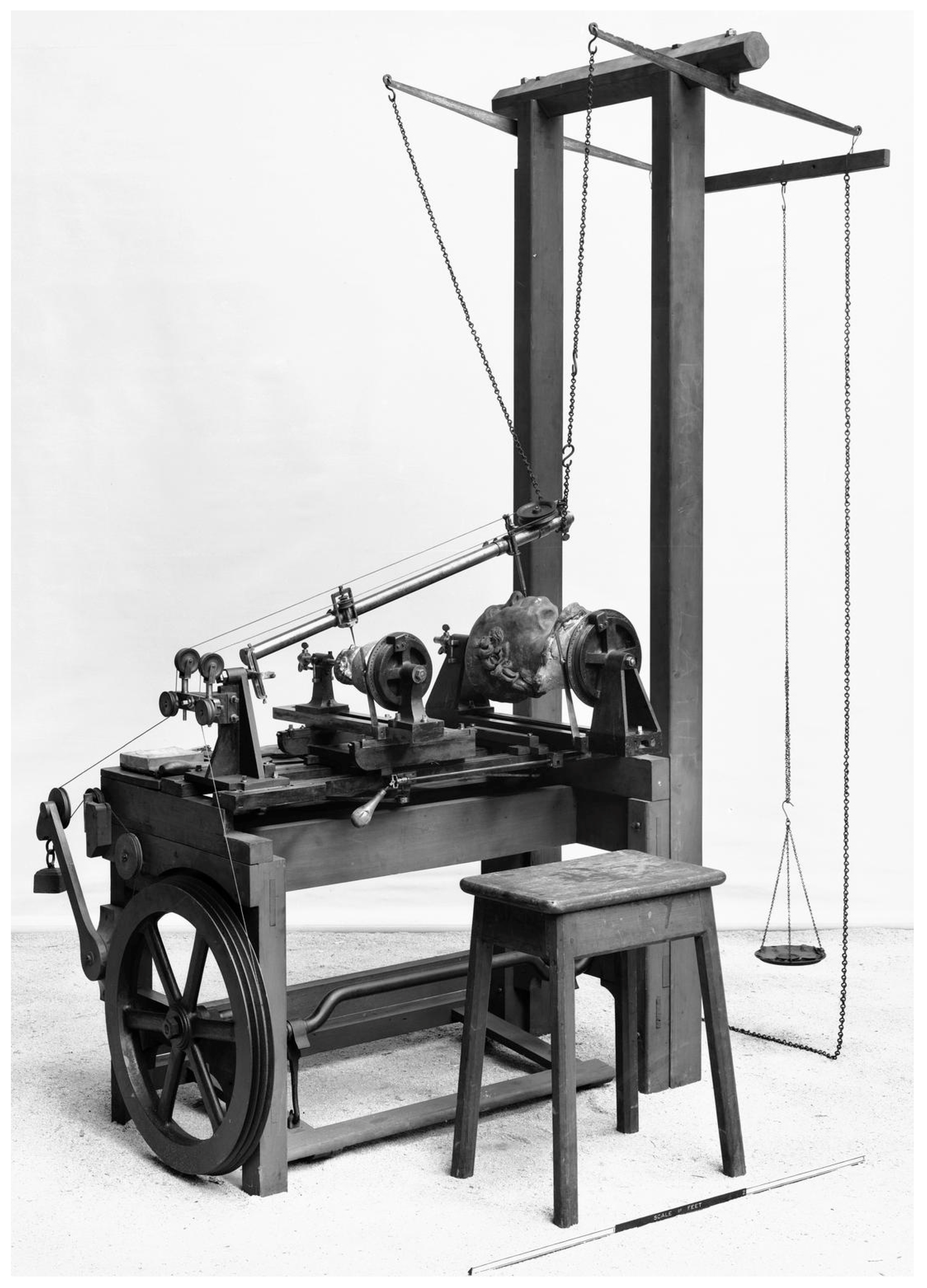
Photo 21.
3D-pantograph designed and built by J. Watt, 1807. The mechanism is intended for the automatic production of reduced copies of sculptures (Science Museum, London, sciencemuseumgroup.org.uk).
Photo 21.
3D-pantograph designed and built by J. Watt, 1807. The mechanism is intended for the automatic production of reduced copies of sculptures (Science Museum, London, sciencemuseumgroup.org.uk).
The kinematic diagram of the pantograph built by Benjamin Cheverton [76] in 1826 (see Photo 22) is the closest to the kinematic diagram of the modern 3D-pantograph (see Figure 2). While building the pantograph, Cheverton relied on the design previously proposed by John Hawkins. [77] Just like the Watt pantograph, the Hawkins-Cheverton pantograph was intended to produce the reduced copies of sculptures.
It should be noted that both the Watt pantograph and Hawkins-Cheverton pantograph had a built-in engraver, whose milling cutter performed mechanical processing of a billet. An engraver is not required in the methods of creation of the polygonal masonry considered above. Therefore, the mechanics of the construction pantograph is much simpler than the mechanics of the Watt and Hawkins-Cheverton pantographs. Ill 2 shows the second half of the 19th century studio, where mass copying of statues was carried out manually using a 3D-pantograph. [78].
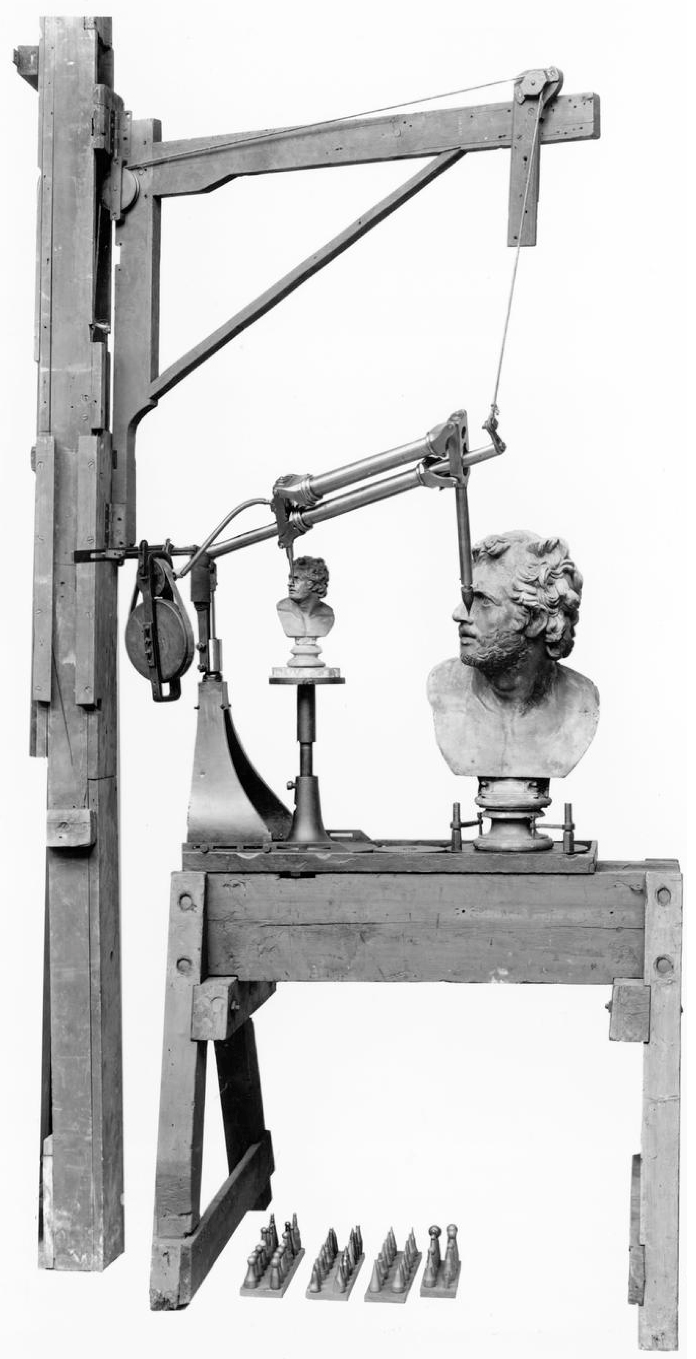
Photo 22.
3D-pantograph designed and built by B. Cheverton, 1826. The mechanism is intended for the automatic production of reduced copies of sculptures (Science Museum, London, sciencemuseumgroup.org.uk).
Photo 22.
3D-pantograph designed and built by B. Cheverton, 1826. The mechanism is intended for the automatic production of reduced copies of sculptures (Science Museum, London, sciencemuseumgroup.org.uk).
There is no doubt that, having created a 2D-pantograph at the beginning of the 17th century, the scientists of that time and, first of all, the inventor of the 2D-pantograph himself, Christoph Scheiner, immediately thought about the creation of a 3D-pantograph mechanism with which it would be possible to obtain the reduced/enlarged copies of the three-dimensional objects. Actually, to make transition to three-dimensional objects, the 2D-pantograph just had to be fixed not in the cylindrical, but in a ball or universal joint, and the model and the billet should have the ability to synchronously rotate around their vertical axes by means of a chain transmission (see Figure 2) or a gear transmission [76] (see Photo 22).
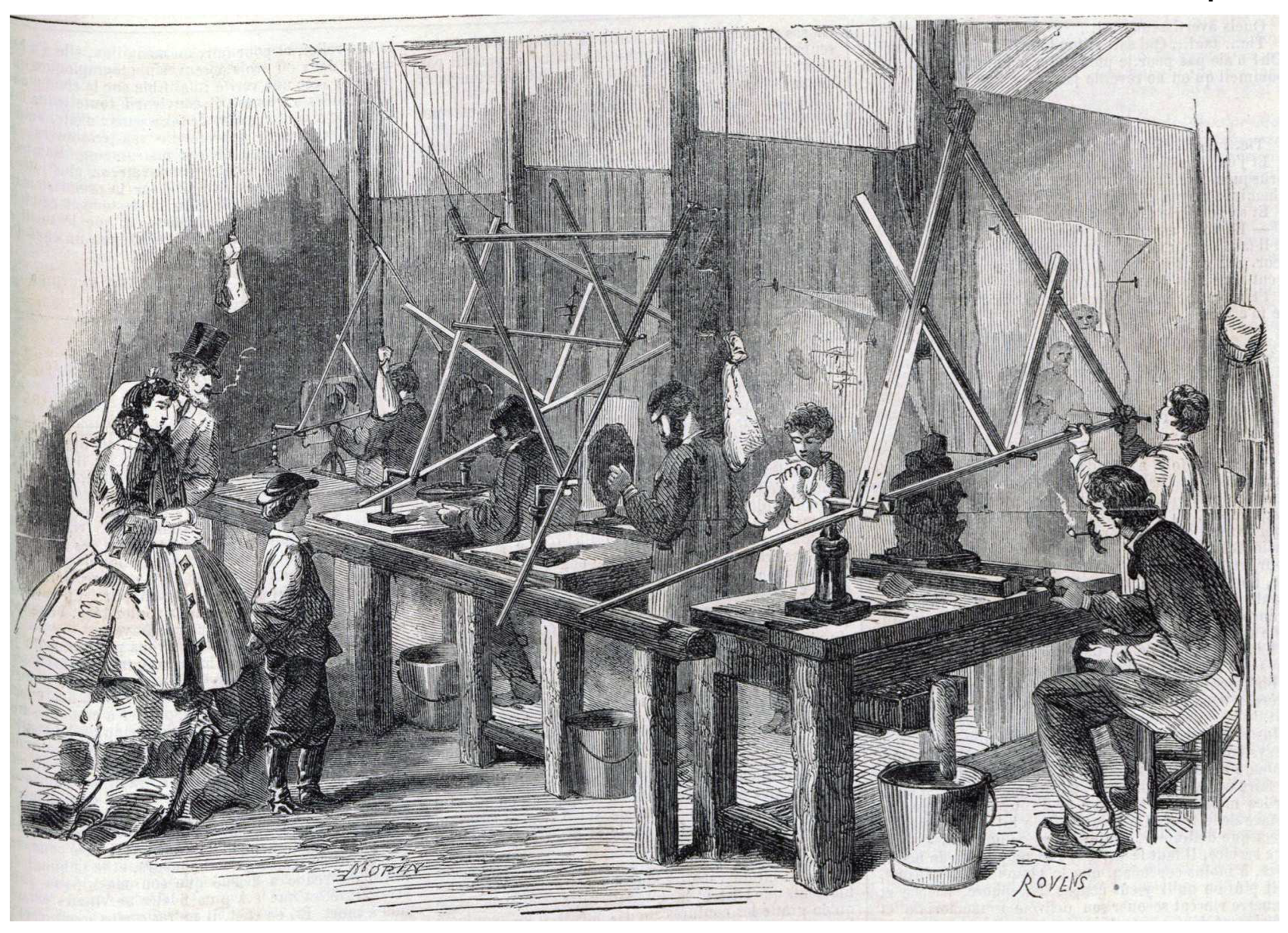
Ill 2.
A 19th century studio of statues manual copying using a 3D-pantograph (ink, artists E. Morin and E. Rovens, 1864).
Ill 2.
A 19th century studio of statues manual copying using a 3D-pantograph (ink, artists E. Morin and E. Rovens, 1864).
Application of the chain transmission in the construction pantograph is more justified in comparison with the gear transmission. The point is that large dimensions and weight of the processing stone blocks result in large dimensions and weight of the used gear wheels. Moreover, the chain transmission makes it easy to change the distance between the rotating platforms, which is responsible for the pantograph reducing/enlarging factor. The distance change is performed by shifting the platforms along the frame. For this purpose, the corresponding number of links is added to or removed from the chain and/or the chain is tightened by a roller located at the end of a spring-loaded console. In this case, the reducing/enlarging factor turns out to be almost continuous. To change the distance in the case of a gear transmission, the installed set of wheels is replaced with the most suitable one among the available sets, the quantity of which is usually limited. Therefore, the reducing/enlarging factor turns out to be strongly discrete.
Analyzing the mechanisms similar to the Singer-Nartov machine, we can conclude that development and building of the modern design 3D-pantograph from the point of view of the kinematic diagram complexity, the metal processing technology, and the used materials were quite feasible for mechanics in the early 18th century already. By that time, all the problems related to the copying accuracy, namely: gaps in the ball and cylindrical bronze joints, backlashes in the chain/gear transmission, as well as all the problems related to the rigidities of the boom, parallelogram mechanism and frame (this is required to keep unchanged the relative position of the pantograph elements during operation) had been successfully solved already. Therefore, it is very strange that it took so much time to create a 3D-pantograph, more than 220 years!
Today, we still have neither written nor material evidence confirming the existence of a construction 3D-pantograph in the 18th century. Nevertheless, taking into account the general state of the art of technology of those times, one cannot exclude a chance that such a pantograph could have been developed, built and could have found a limited usage in construction, but the inventor itself and his pantograph had remained unknown to a wide range of experts. The fact is that the master masons of those days were not in a hurry to disclose their professional secrets. Judging by how long the mystery of creation of the polygonal masonry had persisted, the master masons were able to keep their secrets well.
3.5. Who built this, when, what for and with what funds?
The problem regarding the structures based on the polygonal masonry is as follows. The official history states that the structures had existed before the arrival of Europeans in the New World in the 16th century, and the American Indians did not know either iron tools or a wheel or potter’s wheel, did not have draft animals, did not own brick firing technology, and did not possess a written language at that time. From this statement, there is only one conclusion: the structures were built by some older civilization that existed in America before the Indians, meanwhile whose culture of stone working, in general, corresponded to the European construction culture of the 16-17th centuries.
The problem regarding this mythical older civilization is that it left behind no other material evidences of its existence, except for several perfect stone structures. The high-quality polygonal masonry and the structures based on it appear instantly (by historical standards) as if from nowhere, and then disappear also instantly into nowhere.23 There are neither previous nor subsequent noticeable development in architecture and technology of these structures. This may happen only when a group of professional builders comes to a certain territory for a short period, say, for 10 years, with their own tools, contrivances and construction techniques.
Transience of the events taken place in the construction industry of those years indicates the high productivity of the strange builders and their construction methods. The contradictions are instantly resolved if the authors of the structures are visiting European builders (presumably the Franciscan monastic order) [30,79,80,81,82] and the time of erection of the structures is transferred from “minus infinity” to the 17-18th centuries. For delivery, moving, and rough processing of the stones, slope strengthening, and other heavy and unskilled work, of course, the local Indian people were driven together by orders of the Indian chiefs subdued/bought by the Spaniards. Thus, in a certain sense, the Peruvian megalithic complexes are the structures built by the Incas too, although not so ancient and great.
Any large-scale construction is always based on some strong economic foundation. It is difficult to imagine that the megalithic complexes were built for the Indians at the expense of the Spaniards. Of course, these complexes were created at the expense of the Indians and on bones of the Indians. But what could the Indians offer to the Spanish colonizers? The gold and silver that they had were captured in the early years of the conquest and taken to Europe. The Peruvian land was not able to produce much cotton, sugar cane, or grain.
Since the Indians had gold and silver at the beginning of the conquest, it means they took it somewhere. Therefore, the Spaniards organized large-scale gold but mainly silver extraction in mines and goldfields [82,83,84,85]. And to make the work in the mines more “fun”, the aboriginal priesthood inspired the Indian people with the appearance and grandiosity of the megalithic pagan temples, which were erected by the European builders at the expense of a part of the funds received from the extraction of the precious metals.
Put yourself in the place of those who discovered the mountain of silver in Potosí literally (today this territory belongs to Bolivia) [84]. A lot of low-skilled labor was required to break out the silver-bearing ore and transport it to the silver extraction/smelting place. Where could this workforce be obtained at that time? The sea transportation could not provide a sufficient inflow due to the small tonnage of the ships and extremely high cost of the transatlantic crossing. Of course, the colonialists have offered the Indian chiefs the following mutually beneficial cooperation: we are building a network of temple complexes for you and thereby securing a certain share of your former power for you, while you provide us with people to work in the mines. We take care of the training and maintenance of your people. [86]
After the arrival of the Europeans, a part of the Indian chiefs together with the priesthood realized quickly that it would be possible to retain at least part of the former power only if they went into close cooperation with the invaders. The situation has no difference from what is happening in our time, when the leaders of most countries and their “retinue” have colluded and conduct a treacherous policy towards their own peoples for the sake of preserving their personal position in the arising “brave new world”.
To facilitate the interaction with Indian chiefs, to make it more efficient, centralized, the Europeans provoked a series of clashes between many scattered small Indian tribes (villages). As a result, during the intragroup struggle stimulated by the colonizers, several tribes have distinguished and subjugated the rest. Later, one of these tribes received the loud name Inca “Empire”. The tribe enlargement took place up to a certain degree, which was safe for the occupiers. Likelihood of an uprising or riot was small due to the fact that the tribal leaders, along with their retinue and relatives, were involved in close relations with the Europeans and turned out to be highly dependent on them.
3.5.1. A few words about the role of the Vatican
The Roman Catholic Church (RCC) did not serve Jesus Christ alone at that time, but was a religious center which controlled and guided under its shadow all the major religions and beliefs that existed in the Roman Empire [28,86]. The very word “Catholic” in the name of the church means “universal”, that is, uniting under its wing all religions registered and approved by it.
The Vatican did not care about the specific content of a particular religion at all. The main thing is that the accepted religion would ensure social stability, society manageability, regularity of tax revenues, and order in Rome (Rome heirs after the collapse of the Roman Empire) controlled world regions, where it was practiced. As society developed, the content of the world religions were constantly adjusted in the needed direction to improve the managing efficiency of human masses in the changing technological, economic, and socio-political conditions.
Arriving in the new wild territories, representatives of the Vatican orders studied the language, way of life, culture, social structure, beliefs, myths, tales, legends, habits, world view, cosmology, cultural code, and archetype of the peoples inhabiting these lands. Moreover, the subjects of the study were the nature of the region, minerals, and climate. Having accumulated knowledge about the region, on the basis of the existing religious beliefs of the tribes living there, as well as using own groundworks made previously, an “enhanced” local religion was gradually creating for this region with a specific host of gods, special rituals, original style in architecture and temple design, etc.
As the savage peoples were integrated into the modern society of the time, the complexity of the updated local religion and its rites increased gradually. Often the process of evolution of the local religion ended with its merging with the Christian teaching (the ideal religion for slaves). This happened with certain reservations and deviations from the canons accepted in Europe. These deviations took into account local traditions and colour. [87,88] Such a merging can be observed today everywhere in Central and South America, where RCC influence was especially strong [86].
The fact is that the Vatican did not worship Jesus alone in those years. In particular, this is eloquently indicated by the tombstones on the graves of none, but the Roman popes [28,86]! Christian symbolics on the graves of the Roman popes appear only since the beginning of the 19th century. Until the 19th century, the graves of the Roman popes had symbolics and imageries of the Old Testament (Judaism) and deities of the “ancient” Rome. Thus, up to the 19th century, the Roman popes were not Christians, they were Jews and/or pagans!
The following fact attracts attention: in many regions of the world there is and often more than one large cult, whereas an own large local religion different from Christian has failed to arise on the vast territory of both Americas. Observing scales of the megalithic construction on the territory of Peru, one can assume that here, for the entire region of South America, the Vatican planned to create another world religion, another world religious center. However, after many years of hard work, something did not work out, something went wrong.
Perhaps, there were limitations in funds; perhaps, the local human substrate turned out to be unsuitable; perhaps, there was a persistent food shortage; perhaps, the level and training of the Vatican experts sent to Peru were not up to par; perhaps, the concept has changed – it was decided that all religions should gradually be reduced to the single Christian creed. Perhaps, several of the above reasons worked at the same time or there were some other reasons that are still unknown to us. Anyway, the decision to terminate the new creed development for the South American region was made and the project was abandoned.
The Vatican involvement in the “design” of religions in various regions of the world is easily traced by the general features of the key actors of the world religions and by the similar events occurring with these actors. The immaculate conception of the heroes, the demonstration of miracles by them, the accomplishment of feats, a brutal killing of the hero and his subsequent triumphal resurrection from the dead, the ascension of the hero to heaven (Osiris, Mitra, Dionysus, Krishna, etc.) gives out a common source, a common template underlying many world religions, which is just adapted to different local cultures [87,88,89].
3.5.2. The Monroe Doctrine
Although the Monroe Doctrine [90] was openly proclaimed only in 1823, however, the hatching of secret plans of this doctrine, partially voiced by the fifth US President James Monroe, certainly took place much earlier. One of the goals of the Monroe Doctrine was to oust the Spanish Empire [91] from the territories of both American continents. In accordance with the set goal, all the achievements of the Spaniards in North, Central, and South Americas should be downplayed, and, on the contrary, all the negative aspects associated with the colonization should be exaggerated. Thus, the concealment of the real historical events, including the concealment of the authorship of the megalithic structures with the unique type of the polygonal masonry, turned out to be both in the interests of the RCC and in the interests of the United States, which was rapidly strengthening in those years.
3.5.3. In the bottom line
So, the RCC sought to hide its unacceptable from the viewpoint of the modern Christianity participation in support and development of the pagan cult in Peru and the US authorities wanted to belittle the achievements of Spanish builders and “appointed” the Incas as the authors of the polygonal structures by proclaiming the Inca Empire that never existed in history. Nowadays, the polygonal structures are the national pride of the Peruvians. Much young generations of native Indians have been brought up on these impressive monuments of the past. Therefore, the Peruvian authorities will never give up this heritage of “their Indian ancestors”. The truth is not needed to anyone.
Returning to the economy of Peru of that time. After a few decades of intensive extraction, the easily accessible gold and silver deposits have been exhausted, the cost of mining of the precious metals has increased, the initial plans of the Vatican regarding the development of a large local pagan cult in the area have changed and the construction of the megalithic complexes has stopped. By this time, the power of the Spaniards and the Catholic Church had increased somehow “imperceptibly”, and the number of the Indians was greatly reduced in some “incomprehensible” way [84]. Poor food and living in shacks did not add health to the miners, the places of “power” did not longer compensate for the powers taken away by exhausting work in the mines.84 In general, the time has come when some of the abandoned religious structures of the Indians could finally be put to good use without much trouble. And these structures have been put to good use. Stone blocks and parts of the structures were used for erection of Catholic cathedrals, abbeys, palaces, villas, urban and industrial buildings.
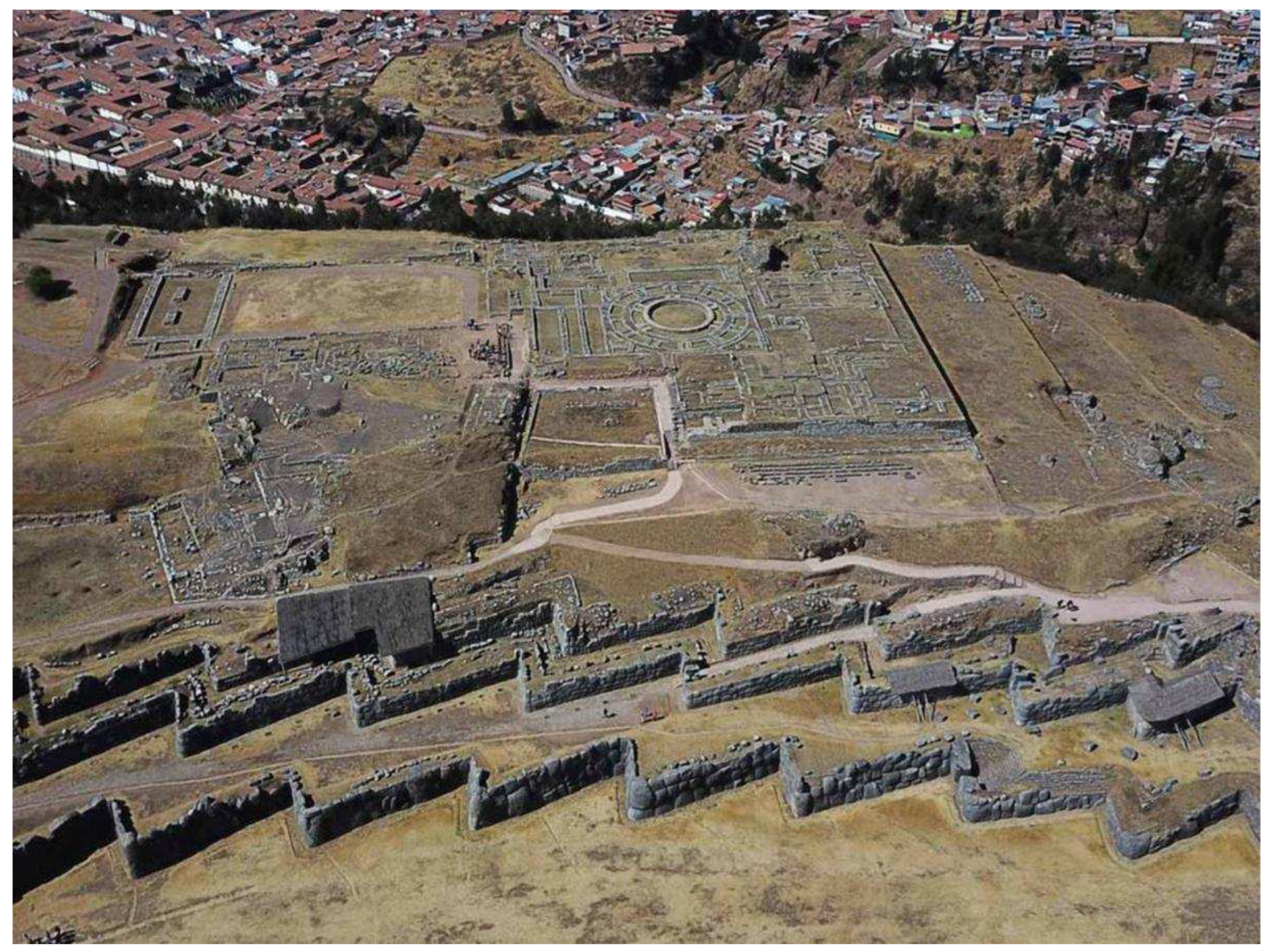
Photo 23.
A bird's-eye view of the Fortress Sacsayhuaman; the south is at the top of the picture, the north is at the bottom (www.ollantaytambo.org). Three tiers of the indented bastions and the groundwork remains of a cylindrical citadel are clearly visible. Below is the city of Cusco.
Photo 23.
A bird's-eye view of the Fortress Sacsayhuaman; the south is at the top of the picture, the north is at the bottom (www.ollantaytambo.org). Three tiers of the indented bastions and the groundwork remains of a cylindrical citadel are clearly visible. Below is the city of Cusco.
3.6. Fortress Sacsayhuaman – the simplest star-shaped fortress
What else does indicate the European authorship of the Peruvian polygonal buildings as well as the time when they were erected? Let us take a close look at the Fortress Sacsayhuaman (Photos 23 and 24). What is this building? Before us is an early type of fortification work known as a star fortress. [92]
The Fortress Sacsayhuaman occupies one of the heights dominating over the city of Cusco. At one time, the fortress controlled the access roads to the former capital from the north. The Fortress Sacsayhuaman could be used as an interim depository of the silver coins, silver and gold bars prepared for shipment to the Old World; a part of the city treasury could also be located here; in case of a danger, the fortress served as a shelter for local authorities. In addition, the fortress stored stocks of weapons, gunpowder, provisions and other property necessary for survival and retention of power at a critical moment.
Unlike the star fortresses of late construction that survived to our time, the bastions in Sacsayhuaman consist of one face (a long section of the wall) and one flank (a short section of the wall). The chain of these bastions forms an indented (star-shaped) trace [92]. The curtain (a straight section of the fortress wall) is either absent at all here, or is a short section being a continuation of the face. The Fortress Sacsayhuaman has three tiers of the indented bastions. Since the faces are not parallel to the front of an advancing enemy, but they are located at a noticeable angle to it, then the concept of the flank while describing this bastion type can be abandoned at all, instead considering the bastion consisting only of faces – the long and short.
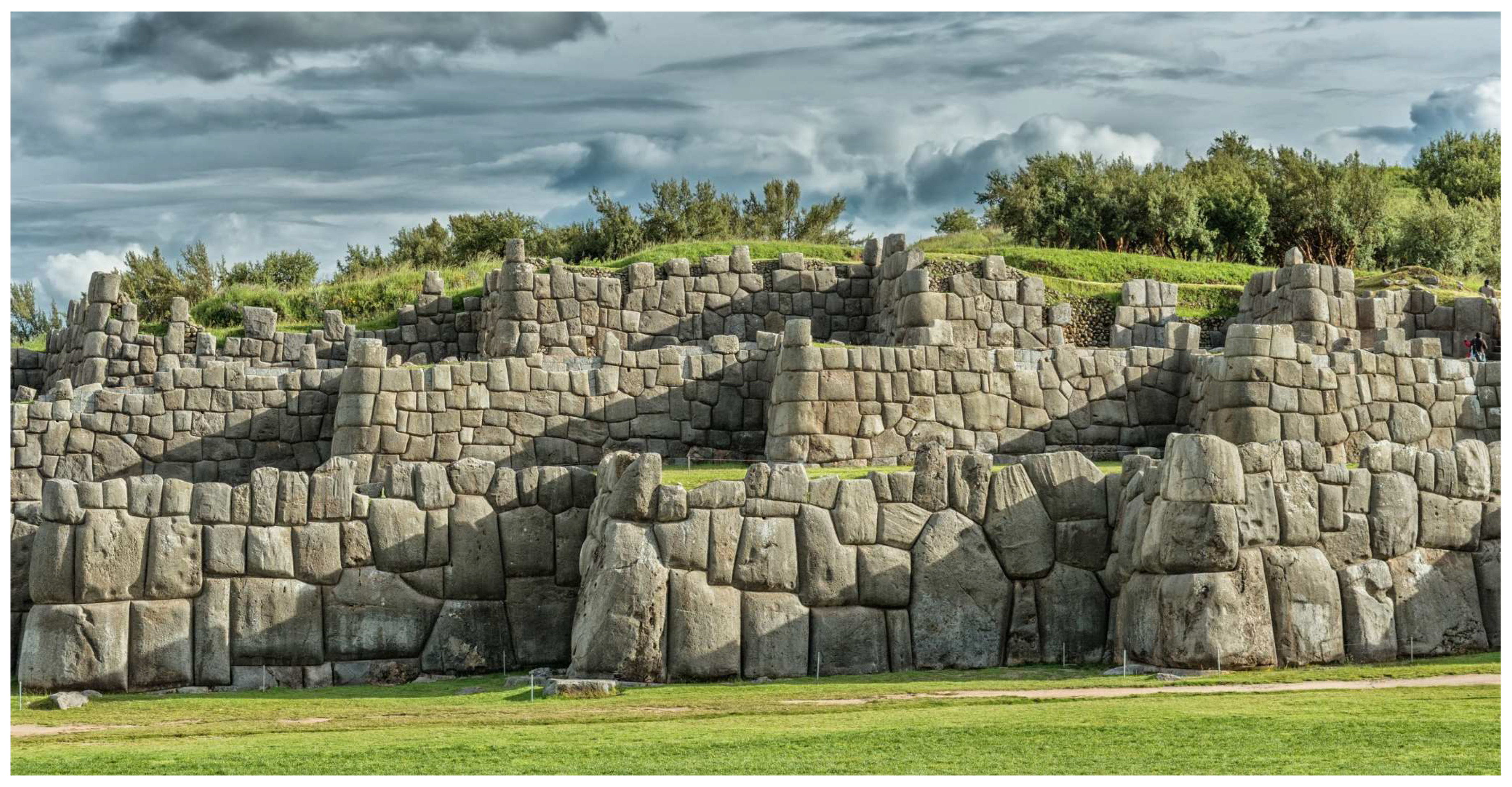
Photo 24.
Arranged in three tiers indented bastions of the Fortress Sacsayhuaman (O. Byelikova, dreamstime.com).
Photo 24.
Arranged in three tiers indented bastions of the Fortress Sacsayhuaman (O. Byelikova, dreamstime.com).
The reason for the observed trace geometry of the Fortress Sacsayhuaman was the desire of the fortress builders to simplify the retaining wall as much as possible minimizing the number of kinks per a bastion. Despite this simplification, the possibility of firing at the approaches to the face (and the face itself) of the bastion located on the right, and firing at the approaches to the flank (and the flank itself) of the bastion located on the left remains. Impossibility of the complete cross-firing of the enemy located near the fortress wall between the adjacent bastions or climbing this wall should be considered as a disadvantage of this trace. Nevertheless, the presence of a rifleman in the corner between the bastions makes it possible to fire along both rather short sections of the fortress walls coming out from this corner and, thus, partially ensure the cross-firing ability at these locations.
Unlike a typical star fortress, the chain of the indented bastions of the Sacsayhuaman does not form closed defense rings in its current state at least. Nevertheless, as a star fortress should be, it had a citadel inside. Judging by the groundwork remains, the citadel was a cylindrical tower.
Unlike a typical star fortress, the use of cannons was not envisaged in the Sacsayhuaman. There is simply no place for them in the star rays (bastions). The use of cannons even of a small caliber (there should be two for each bastion at least to cover the face of the bastion on the right and the flank of the bastion on the left) would require a significant increase of the bastion size. Moreover, the number of the bastions should be significantly less, since the distance between the bastions in the case of use of cannons cannot be so short as in the Sacsayhuaman. Finally, cannons are too powerful weapons against the Indians and other more strong enemy was not expected at that time.
If an enemy overcame the first fortress wall, the fortress defenders in the second defense echelon as well as the joined to them survived defenders from the first echelon opened fire on him. In the case of the second echelon capture, the situation was repeated – the survived defenders of the first and second fortress walls joined the defenders of the third wall. Each next defense echelon is a chain of the indented bastions located in such fortresses above the previous one forming tiers. In the event of the third echelon surrender, the survived defenders took refuge in the citadel – the last line of fortress defense, and fired the enemy through the embrasures available there.
One of the key parameters of the star trace is the distance between the vertices of the neighboring rays (distance between the ray vertice at the parapet level of a bastion and the ray vertice at the foot level of a neighboring bastion). In the Sacsayhuaman, this distance changes within the range 10-30 meters, it makes about 18 meters on average (the estimate relates to the lower bound as the bastion heights were not taken into account) [63]. Another important trace parameter is the value of the outward protrusion of the star rays (bastions), that is, how long the rays are. In the Sacsayhuaman, the ray lengths make about 6 meters on average [63]. Finally, the third parameter of the fortress, which should be taken into account, is the distance between the going parallel fortress walls (actually, stone-faced earthen ramparts). The distance between the first and the second walls makes about 8 meters on average; between the second and the third – about 3 meters on average [63].
The presented parameters of the Fortress Sacsayhuaman definitely indicate a weapon that was used for its defense. This weapon must have the aiming range of shooting and the damaging ability at a distance no less than the spacing between the vertices of the adjacent rays. It is not necessary for such weapon to tear bodies apart and scatter them around the surroundings, it is enough to cripple the attacker so that he would no longer be able to climb the wall or to resist actively. In case the fortress defenders retreat to the overlying tier, the used weapons should effectively hit the enemy who had captured the underlying tiers. When sheltered in the citadel, the weapons used by defenders must continue to be effective against the enemy besieging the citadel.
At the same time, in order to be in safety, the weapons of the fortress defenders should exceed the weapons of the attacking Indians – stones, arrows, and spears in terms of the aimed shooting range and deadly force. Note that the Spanish soldiers were equipped in a leather and metal armor, which could hardly be penetrated by a bullet fired from a flintlock pistol; most of the Indians, on the contrary, did not have any wearable protection. Taking into account that the stones, arrows, and spears had to be thrown upward, i.e., against gravity, the inclined range of aiming throwing among the Indians was about 10-15 meters while preserving a deadly force of their weapons.
Considering the above presented information, a 17-18th century musketoon (known as the blunderbuss in Great Britain or as the trabuco in Spain) – short smoothbore flintlock gun of large caliber (25-29 mm) firing a charge of buckshot, is well suited as the main weapon of the fortress defenders in close combat. [93] In those days, the musketoon was actively used in cavalry, navy and for fortress siege/defense.93 This type of small arms is designed to destroy large masses of weakly protected enemy at short distances up to 30 meters.
It is worth noting that besides the fire properties, during a shot the musketoon generated a deafening (thunderous, hence the name blunderbuss) sound, a bright flash of flame and a lot of gunpowder smoke, which together produced an additional frightening effect on the Indians. Also, do not underestimate the overwhelming, formidable appearance of the Sacsayhuaman Fortress itself, which, in combination with the firearms capabilities, inspired indescribable fear and awe in the Indians.
To destroy the enemy on distant approaches to the fortress, a musket – flintlock gun with a long rifled barrel, was used. Since to repel an attack successfully, there should be two shooters on each indented bastion at least, the garrison of the Fortress Sacsayhuaman had to be consisted of 42 soldiers at least, considering the number of the available (survived to this day) bastions (the first wall includes 20 bastions, the second – 21, and the third – 18).
During construction of the Sacsayhuaman Fortress, it was assumed that the aboriginal Indians would be the main opponent to the regime established in Peru. In general, the armed resistance of the Indians was suppressed in the early years of the conquest. Nevertheless, uprisings broke out periodically and the risk of a major rebellion remained for many years. Gradually, the Indians completely submitted to the new authorities and then quite peacefully coexisted with the Spanish colonizers [30,82,83,84,85,86]. Thus, after some time, the need for a fortress capable to protect from the Indians but unable to protect against a more serious enemy having guns and cannons in their arsenal fell away. Therefore, the Fortress Sacsayhuaman, which required funds for maintenance, was partly disassembled and over time abandoned.
It should be noted in conclusion that the Fortress Sacsayhuaman in comparison with other Peruvian monuments contains perhaps the largest number of suspicious blocks that have signs of casting, sculpting, or plastering (see details in Section 1.3, Section 2.2 and Section 2.5). Since these blocks do not contain any marks and there is no a chart indicating which of the blocks are original, which replace the missing blocks, or which have been restored severely, then any of these dubious blocks of the monument should be considered as a fake, deliberately misleading the public about the antiquity of the building and the methods used for its construction.
3.7. Phenomenon of the “tired” stones
So far, a number of questions regarding the phenomenon of the “tired” stones remain unanswered. The tired stones are scattered in a picturesque mess along the road leading from the quarry to the Fortress Ollantaytambo [6,13]. How could the tired stones have lain for hundreds of years on a road side (some right on the road) [94,95] and even in the town limits [24,96,97,98,99] and not disappear anywhere? The Indians did not worship stone parallelepipeds. Here, if there were, say, niches in these parallelepipeds, especially trapezoidal, then it would be another matter.
Meanwhile, to this day, the finally exhausted stones with incredible persistence continue to show us the way to the quarry, where these too heavy to move blocks for the fortress are believed to have been extracted. Why in the mountainous country, where stones are used for the construction of everything – buildings, bridges, roads; these absolutely weakened stones so conveniently located on the side of the road – take and use, no one has yet been split into smaller parts and put into action? Most of the tired stones are cleft within a day by the efforts of one experienced stonemason. But, instead, we see the complete safety and invulnerability of these stones. It turns out that the local authorities for all these hundreds of years, for some reason, strictly ensured that no one touched these stone blocks.
Surprisingly, the phenomenon of the “tired” stones is found not only in South America. So, for example, there is the “tired” Aswan obelisk [100] in Africa and the well-known no less “tired” Baalbek parallelepipeds [101] in the Middle East. After a crack appeared in the Aswan obelisk, its cutting was stopped, and the quarry, attention, was closed forever. Only the latter circumstance can explain the fact that the obelisk has survived to this day. However, this is impossible in a real quarry, where a discarded large granite block similar to the Aswan is manually split by means of a sledgehammer and steel wedges almost during a day into smaller parts, which are sent to other customers the next day. In the case of the Baalbek parallelepipeds, the fairy tale story has been repeated again.
For hundreds of years, empires arose and collapsed, devastating wars were waged, others came to the place of some peoples on the territories, where the mentioned monuments are located, but, as in Peru, we again see the amazing preservation of these weakened and finally exhausted stone megaliths. Of course, such preservation is impossible without participation of local authorities. So, all this time some powers forced the local authorities to ensure strictly that nothing happened to these artifacts of the “distant” past.
3.8. Fabrication of symmetrical statues by means of a 3D-pantograph
The casting method, in which, first, a core (solid or hollow) of cheap concrete47 is cast, and then, after the end of core shrinkage, a comparatively thin shell (“plaster” layer) of more expensive artificial granite is cast over (see Section 2.2), due to its complexity is not suitable for the large-scale polygonal construction, in which all the stone blocks are different. Meanwhile, this method is great both for making single unique statues and for mass production of identical statues. Note that geopolymeric concretes [48] of appropriate compositions could also be used as concrete for the core and the outer shell.
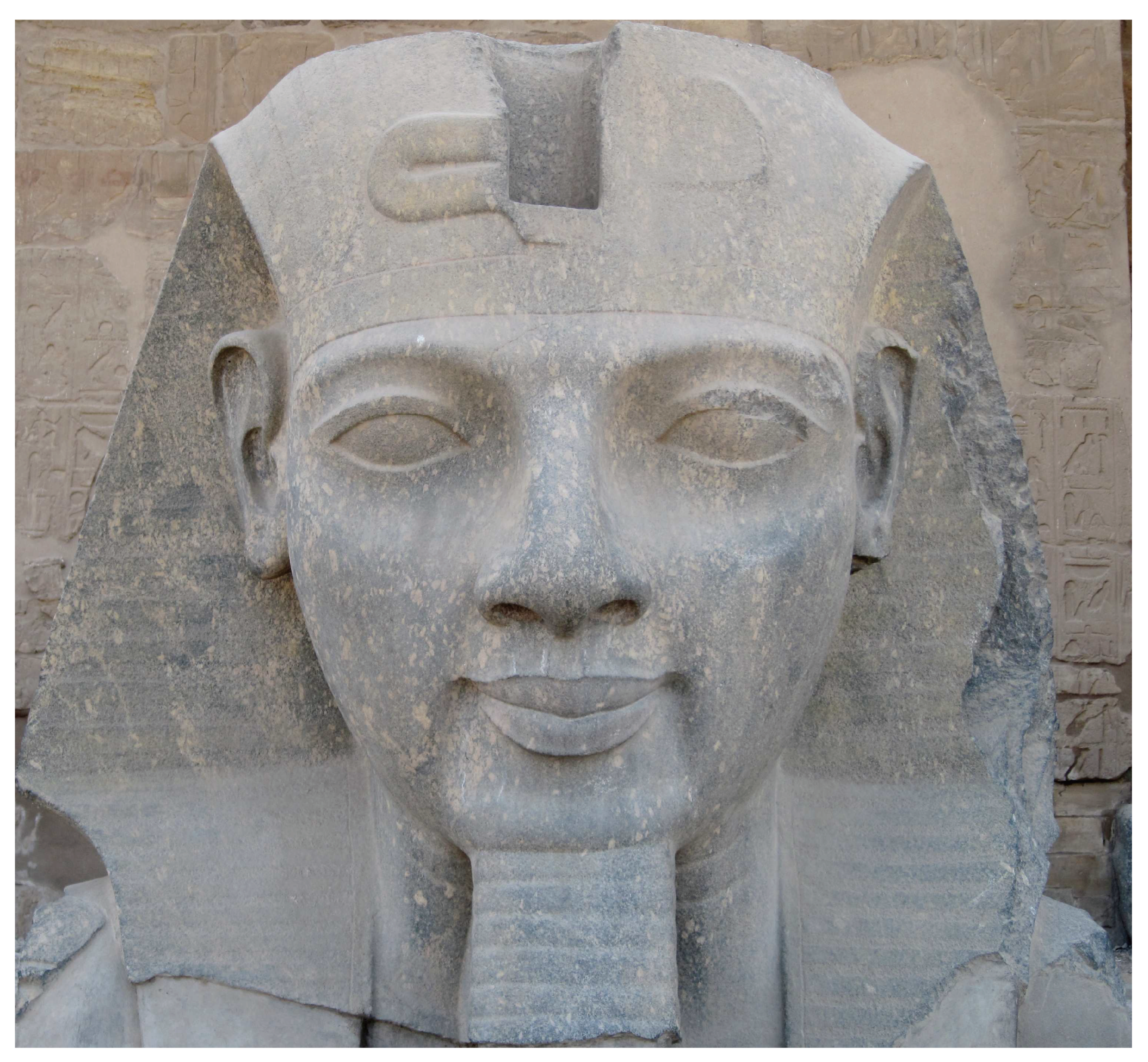
Photo 25.
Bust of pharaoh Ramses II in Luxor, Egypt (2011, wikimedia.org). The symmetry of the sculpture is noteworthy.
Photo 25.
Bust of pharaoh Ramses II in Luxor, Egypt (2011, wikimedia.org). The symmetry of the sculpture is noteworthy.
For example, some “Ancient” Egyptian statues of pharaohs and sphinxes covered with a layer of plaster of artificial stone (granite, dolerite) were apparently fabricated using this technology [49,53]. Since among some “Ancient” Egyptian statues there are statues that differ only in size, it can be assumed that these statues were created by the same original model using the 3D-pantograph adjusted for different enlargement factors.
A number of researchers have long drawn attention to the perfect enough symmetry (face, headdress, torso) of some Egyptian statues (Ramses II, Amenhotep III, Nefertiti), see Photo 25. [102] The question of how this symmetry was accomplished remained open for a long time. Meanwhile, a small modification of the pantograph mechanism makes it possible to produce statues with a high degree of symmetry of the left and the right sides [53]. Let us show how this was achieved in practice.
First, as usual, a sculptor creates an enlarged clay model by the reduced clay model with help of the pantograph [33,34]. After that, the 0-shaped chain in the pantograph is replaced with an 8-shaped one. As a result of this modification, the platform with the reduced model of the statue and the platform with the enlarged model of the statue will rotate in mutually opposite directions. If the used pantograph has an intermediate gear wheel [76] (in the general case, an odd number of identical intermediate gear wheels) to drive the platforms instead of the chain, then a pair of identical intermediate gear wheels (in the general case, an even number of identical intermediate gear wheels) should be installed instead of this wheel or exclude any intermediate wheels at all.
Now the sculptor by considering the artistic merits of the left and right halves of the reduced model of the statue should decide – which side of the statue he wants to exactly copy to its other side. Having decided on the side, let it be the left side for definiteness, the sculptor applies the probe to the left side of the reduced model. In this case, the pantograph pointer will show the corresponding point in space on the right side of the enlarged model. If there is an excess of clay at the indicated point, then it is removed directly by the pantograph pointer; if there is a shortage, then the sculptor adds the necessary amount of clay to this point.
When touching the model with the pantograph probe, the probe should be guided so that the straight line passing along it crosses the vertical axis of the model rotary platform (Table A in Figure 2) at 90° angle. In order to use the pantograph with probe directions different from the one specified (general case of touching the model surface at an arbitrary angle), the parallelogram mechanism should be replaced with an antiparallelogram [31] mechanism. To do this, the long bars of the parallelogram just need to be moved into the place of the parallelogram diagonals.
Thus, applying the modified pantograph, it is possible to obtain a sculpture which left and right halves are highly symmetrical. Deviations from symmetry in such sculpture are determined by the error of the pantograph mechanism and the errors of the used fabrication technology (depending on the sculpture size, the total error ranges from a few to a dozen millimeters). To reduce the effect of the pantograph error, the symmetrization work of a head, for example, should start from the nose tip, where the error will be zero, and end at the back of the head, where the error will be the greatest, but least noticeable.
Note that a gradual increase in the symmetry violation from the nose to the back of the head will be a sign of the technology based on use of a 3D-pantograph. To detect such violation, it is best to use a coordinate measuring machine (CMM), [103] which error much less than the error of the 3D-pantograph (depending on the sizes of the measured body, the CMM error ranges from a few to hundreds of microns).
There are several polygonal buildings that have short sections of masonry with a symmetrical arrangement of blocks (Sacsayhuaman, Ollantaytambo). However, the symmetry at these sections is only approximate (see, for example, Photo 12). The blocks on the left and on the right sides of the vertical axis of symmetry are not completely reflection symmetric, they differ in shape and size. Thus, the technical opportunity provided by the 3D-pantograph, that allows to create the polygonal masonry with exactly reflection symmetric sections, was either unknown to the builders of the polygonal complexes at that time or was not simply used.
4. Discussion
Among the materials related to the topic, work [20] should be noted. The author suggested to use a reduced gypsum model of a stone block and to perform transferring and scaling of a complicated surface geometry with a caliper by several reference points. The gypsum model is usually required to avoid wearing of the original clay model while producing copies. This problem does not arise while fabricating blocks for the polygonal masonry. Moreover, in the case when the block clay model is formed initially by a stone billet of arbitrary shape, it is used just once and then thrown out (or serves as a core for a new model). Thus, in order to reach the required result, possessing only a clay model of the block is quite enough.
The transferring process of a complicated surface geometry and its scaling by few reference points using the caliper is very time-consuming and inaccurate. However, this process ceases to be time-consuming and inaccurate if we apply the 3D-pantograph instead of the caliper. Analysis shows that in most cases, first, a reduced clay model is created by a stone billet of an arbitrary shape using the 3D-pantograph. Then, the regions are cut out in the clay model of the block for interfacing with neighboring blocks. After that, a model wall is assembled of the model blocks. After drying, the wall is disassembled, and the interface regions of the model blocks are transferred to their stone billets by means of the 3D-pantograph.
Technically, the topography translator is comparable in terms of complexity to a 2D-pantograph which creation dates back to the beginning of the 17th century. The knowledge accumulated in the field of mechanics and the technology level achieved by the beginning of the 18th century could quite allow to design and build the 3D-pantograph suitable for construction needs. Thus, the most complex polygonal masonry obtained with the 3D-pantograph by clay models should be dated to the beginning of the 18th century, and the simpler ones obtained with the topography translator should be dated to the beginning of the 17th century.
The Fortress Sacsayhuaman was built by the Spaniards no earlier than the 17th century, since its very appearance and the defense concept adopted at that time closely related to the small arms available at that moment clearly indicate this. No earlier than the beginning of the 18th century, the polygonal bas-reliefs and the polygonal giant Face Towers of the Cambodian temple complex Angkor as well as a number of the “Ancient” Egyptian giant statues known for their symmetry should be dated, since the 3D-pantograph was needed to create all of these monuments.
Photographs
Photos 2-16 show the polygonal masonries which can be obtained by using the methods suggested in the article. The distinctive features of these masonries are: the stone blocks are large weighing from several hundred kilograms to several tons; the blocks are mated to each other closely without a gap through complicated curved and extensive surfaces.
Acknowledgments
I thank O. V. Obyedkov, Prof. I. K. Fomenko, O. E. Lyapin, Dr. V. M. Soroka, and D. V. Pisarenko for critical reading of the manuscript, assistance and support in conducting this research.
Used materials
- “Polygonal masonry”, Wikipedia.
- “List of earthquakes in Peru”, Wikipedia.
- C. Cuadra, “Dynamic characteristics of Inca’s stone masonry”, ch. 15, pp. 421-460 in book “Masonry construction in active seismic regions” (series in civil and structural engineering), edited by R. Rupakhety, D. Gautam, 466 pp., Woodhead Publishing, 2021. [CrossRef]
- M. A. Rodríguez-Pascua, C. Benavente Escobar, L. Rosell Guevara, C. Grützner, L. Audin, R. Walker, B. García, E. Aguirre, “Did earthquakes strike Machu Picchu?”, Journal of Seismology, vol. 24, pp. 883-895, 2020. [CrossRef]
- K-G. Hinzen, A. Montabert, “Rectangular blocks vs polygonal walls in archaeoseismology”, Annals of Geophysics, vol. 60, no. 4. pp. S0443-0460, 2017. [CrossRef]
- J.-P. Protzen, “Inca quarrying and stonecutting”, Journal of the Society of Architectural Historians, vol. 44, no. 2, pp. 161-182, 1985. [CrossRef]
- E. Laroze, A. Garric, “La technique du sciage des joints dans la maçonnerie ptolémaïque en grès”, Bulletin de l'Institut Français d'Archéologie Orientale (BIFAO), vol. 113, pp. 239-282, 2013 (in French).
- I. I. Ishchenko, “Technology of stone and installation works”, 336 pp., Higher School, Moscow, 1988 (in Russian).
- “Pantograph”, Wikipedia.
- “Polygonal wall” in Delphi, Greece, Wikipedia.
- B. Clifford, W. McGee, M. Muhonen, “Recovering cannibalism in architecture with a return to cyclopean masonry”, Nexus Network Journal, vol. 20, pp. 583-604, 2018. [CrossRef]
- O. J. Outwater, “Building the fortress of Ollantaytambo”, Archaeology, vol. 12, no. 1, pp. 26-32, 1959.
- J.-P. Protzen, “Inca architecture and construction at Ollantaytambo”, Oxford University Press, 303 pp., New York, Oxford, 1993.
- V. R. Lee, “The building of Sacsahuaman”, Journal of Andean Archaeology (Ñawpa Pacha), vol. 24, iss. 1, pp. 49-60, 1986.
- E. M. Shilin, “Polygonal masonry in Peru in South America – a particular view of an architect”, Projects-of-brick-houses.rf (in Russian).
- H. Tributsch, “On the reddish, glittery mud the Inca used for perfecting their stone masonry”, Journal of Earth Sciences & Environmental Studies, vol. 3, iss. 1, pp. 309-324, 2017. [CrossRef]
- D. Andrea, “A theory on Incas' stone fitting techniques”, 2002.
- Alexander, “Polygonal masonry: cottage technologies”, YouTube, 2015 (in Russian).
- Alexander, “Polygonal masonry: cottage technologies II”, YouTube, 2016 (in Russian).
- Unraveling History, “How was the polygonal masonry made?”, YouTube, 2019 (in Russian).
- Alexander Tamansky, “Inca megaliths, polygonal masonry and lie of historians”, YouTube, 2021 (in Russian).
- E.G.Warland, “Modern practical masonry”, Darien Press, 284 pp., Edinburgh, 1929.
- GRESAR, “Traces of somebody else's technologies”, parts 1-10, YouTube, 2019-2021 (in Russian).
- P. Garcia, “Archaeological restoration and heritage actions in Ollantaytambo”, Heritage, vol. 1, iss. 2, pp. 392-413, 2018. [CrossRef]
- Google street view, Corner of Maruri and Qapchikijllu St. in Cusco, 2022.
- SGD Sacred Geometry Decoded, “Fire & quickly working granite on Egyptian obelisks: Not quite lost ancient technology”, YouTube, 2023.
- “Terrace (earthworks)”, Wikipedia.
- A. Tamansky, “The other history of Roman Empire”, 617 pp., 2023.
- Alexander Tamansky, “When did cities emerge?”, YouTube, 2021 (in Russian).
- Alexander Tamansky, “Roman roads of pre-Columbian America”, YouTube, 2021 (in Russian).
- I. I. Artobolevsky, “Mechanisms in modern engineering design: A handbook for engineers, designers and inventors”, vol. 1, Mir, Moscow, 1976.
- M. Rogińska-Niesłuchowska, “The pantograph and its geometric transformations – a former popular tool for copying and scaling”, The Journal of Polish Society for Geometry and Engineering Graphics, vol. 29, pp. 59-65, 2016.
- Michael Keropian, “3D Pantograph enlarging”, parts 1-7, YouTube, 2018.
- Michael Keropian, “Enlarging and reducing sculpture, 3D pantograph”, Michael Keropian Sculpture.
- “Pulley”, Wikipedia.
- “Block and tackle”, Wikipedia.
- “Winch”, Wikipedia.
- “Crane (machine)”, Wikipedia.
- SGD Sacred Geometry Decoded, “How the ancients could move & place megaliths with primitive tech”, YouTube, 2022.
- SGD Sacred Geometry Decoded, “Coral Castle explained & the mystery making methodology explained”, YouTube, 2022.
- SGD Sacred Geometry Decoded, “How to precisely steer a megalith with primitive technology”, YouTube, 2022.
- SGD Sacred Geometry Decoded, “Ancient cranes are modern cranes gears plus compound pulleys”, YouTube, 2020.
- D. Schilling, “Spiezer сhronik”, p. 755, Manuscript, 806 pp., 15th century (Burgerbibliothek, Mss. Hist. Helv. I16, Bern, in German).
- Google street view, Hatunrumiyoc St. in Cusco, 2018.
- “Masonry”, The Encyclopædia Britannica. A dictionary of arts, sciences, literature and general information, vol. XVII, p. 841, 11th edition, University Press, New York, 1911.
- “Coefficient of thermal expansion”, Wikipedia.
- G. I. Gorchakov, Y. M. Bazhenov, “Building materials”, 688 pp., Stroyizdat, Moscow, 1986 (in Russian).
- J. Davidovits, F. Davidovits, “The pyramids. An enigma solved”, 427pp., 2nd edition, Geopolymer Institute, Saint-Quentin, 2001.
- Tamansky International, “When did Ancient or Classical Egypt end?”, YouTube, 2022 (in Russian).
- Tamansky International, “Incomprehensible technologies and construction speed of the granite embankments in St. Petersburg”, YouTube, 2022 (in Russian).
- Tamansky International, “Unique and never repeated granite technologies of St. Petersburg”, YouTube, 2022 (in Russian).
- Tamansky International, “The secret of artificial granite of St. Petersburg is almost unraveled”, YouTube, 2022 (in Russian).
- R. V. Lapshin, “How did an unknown sculptor achieve perfect enough symmetry of the face of the Egyptian pharaoh Ramses II?” (under preparation).
- D. Ogburn, B. Sillar, J. C. Sierra, “Evaluating effects of chemical weathering and surface contamination on the in situ provenance analysis of building stones in the Cuzco region of Peru with portable XRF”, Journal of Archaeological Science, vol. 40, pp. 1823-1837, 2013. [CrossRef]
- SNT chairman, “Who did really build Kronstadt?”, YouTube, 2019 (in Russian).
- “Angkor”, Wikipedia.
- “Plumb level”, Designing Buildings, the construction wiki.
- “Plumb bob”, Wikipedia.
- “Marking gauge”, Wikipedia.
- Built Heritage Education, “Learn Stonemasonry - 3 - Stone Cutting Techniques”, YouTube, 2023.
- Ray Sumner, “Stonemason lecturer Ray Sumner chamfer demo”, YouTube, 2013.
- M. Haduck, “Rockfacing and shaping stones (Part 13)”, YouTube, 2022.
- J.-P. Protzen, “The fortress of Saqsa Waman: was it ever finished?”, Journal of Andean Archaeology (Ñawpa Pacha), vol. 25, iss. 1, pp. 155-175, 1987. [CrossRef]
- “Bossage”, Wikipedia.
- M. Haduck, “Derrick & cranes (Maine Granite Museum)”, YouTube, 2022.
- “Climate of Peru”, Wikipedia.
- “Non-contact profilometers”, Wikipedia.
- “Christoph Scheiner”, Wikipedia.
- C. Scheiner, “Pantographice seu ars delineandi res quaslibet per parallelogrammum lineare seu cavum, mechanicum, mobile”, 108 pp., Typographia Ludouici Grignani, Rome, 1631 (in Latin).
- “Andrey, K. Nartov”, Wikipedia.
- “Turning machine for medal copying”, State Hermitage Museum, St Petersburg.
- V. V. Danilevskiy, “Nartov and his “Clear insight into machines””, edited by A. S. Britkin, 271 pp., Mashgiz, Moscow, Leningrad, 1958 (in Russian).
- “James Watt”, Wikipedia.
- “Reducing sculpture copying machine”, Science Museum, London.
- J. P. Muirhead, “The life of James Watt, with selections from his correspondence”, pp. 454-466, 2nd revised edition, 572 pp., John Murray, London, 1859.
- “Machine for reproducing sculpture”, Science Museum, London.
- “John I. Hawkins”, Wikipedia.
- T. Gauthier, “Photosculpture”, Le Monde illustré, pp. 396-398, December 17, 1864 (in French).
- Alexander Tamansky, “Who and when did build the Egyptian pyramids?”, YouTube, 2020 (in Russian).
- Alexander Tamansky, “How were the Egyptian pyramids built?”, YouTube, 2021 (in Russian).
- Alexander Tamansky, “Who did build the American pyramids?”, YouTube, 2021 (in Russian).
- Alexander Tamansky, “American silver in Roman coins”, YouTube, 2021 (in Russian).
- “Global silver trade from the 16th to 19th centuries”, Wikipedia.
- P. Bakewell, “Miners of the Red Mountain: Indian labor in Potosí, 1545-1650”, 213 pp., University of New Mexico Press, Albuquerque, 1984.
- J. J. TePaske, “A new world of gold and silver”, edited by K. W. Brown, 340 pp., Brill, Leiden, Boston, 2010.
- Tamansky International, “Pagan Catholicism of the Latin America”, YouTube, 2022 (in Russian).
- N. A. Morozov, “Christ – The history of human culture in the light of natural science”, vol. 4, 816 pp., State Publishing House, Moscow – Petrograd, 1928 (in Russian).
- N. A. Morozov, “Asian Christs – The history of human culture in the light of natural science”, vol. 9, 580 pp., Kraft+, Moscow, 2003 (in Russian).
- G. V. Nosovsky, A. T. Fomenko, “New Chronology of Egypt – Astronomical dating of Ancient Egypt monuments, Studies 2000-2002”, 560 pp., AST, Moscow, 2007 (in Russian).
- “Monroe Doctrine”, Wikipedia.
- “Spanish Empire”, Wikipedia.
- “Fortification and siegecraft”, The Encyclopædia Britannica. A dictionary of arts, sciences, literature and general information, vol. X, p. 686, fig. 15, 11th edition, University Press, New York, 1910.
- L. K. Makovskaya, “Hand firearms of the Russian Army from the end of the 14th to the 18th century”, 219 pp., Voenizdat, Moscow, 1992 (in Russian).
- Google street view, Route 28B, 2022.
- Google street view, Route 28B, 2022.
- Google street view, Principal St. in Ollantaytambo, 2022.
- Google street view, Principal St. in Ollantaytambo, 2022.
- Google street view, Principal St. in Ollantaytambo, 2022.
- Google street view, Principal St. in Ollantaytambo, 2022.
- “Unfinished obelisk”, Wikipedia.
- “Baalbek Stones”, Wikipedia.
- C. Dunn, “Lost technologies of ancient Egypt: advanced engineering in the temples of the pharaohs”, 400 pp., Bear & Company, 2010.
- “Coordinate-measuring machine”, Wikipedia.
Disclaimer/Publisher’s Note: The statements, opinions and data contained in all publications are solely those of the individual author(s) and contributor(s) and not of MDPI and/or the editor(s). MDPI and/or the editor(s) disclaim responsibility for any injury to people or property resulting from any ideas, methods, instructions or products referred to in the content. |
© 2024 by the authors. Licensee MDPI, Basel, Switzerland. This article is an open access article distributed under the terms and conditions of the Creative Commons Attribution (CC BY) license (http://creativecommons.org/licenses/by/4.0/).
Copyright: This open access article is published under a Creative Commons CC BY 4.0 license, which permit the free download, distribution, and reuse, provided that the author and preprint are cited in any reuse.


