
Submitted:
16 November 2026
Posted:
18 November 2026
You are already at the latest version
Abstract
Photovoltaic [PV] systems are fully sustainable energy sources. The PV market in the EU-27 countries is expanding rapidly. The PV market is projected to grow from USD 613.57 billion in 2025 to USD 968.32 billion in 2030, at a compound annual growth rate (CAGR). This publication aims to review and present modern self-cleaning and anti-soiling coatings suitable for protecting PV. The article discusses the current state of knowledge regarding superhydrophobic, hydrophilic, photocatalytic, oleopho-bic, anti-adhesive, and amphiphobic coatings. In technical applications, multiple mechanisms are often combined—for instance, a photocatalytic coating with a super-hydrophilic effect. This analysis aims to indicate limitations of the existing solutions and directions for further research as well as possibilities of improving the durability of self-cleaning systems for the protection of PV modules as a promising tool for re-ducing operational losses. However, it must be emphasized that their effectiveness depends heavily on the climate, the type of soiling, coating durability, and the eco-nomics of system maintenance.
Keywords:
self-cleaning coatings
; photovoltaic modules
; anti-soiling coatings
1. Introduction
In recent years, growing awareness of the negative impact of fossil-fuel-based energy on global warming and climate change has led to a significant surge in interest in PV cell technology. PV energy conversion involves the direct transformation of light into electricity, with no intermediate stages. Consequently, PV cells represent a fully sustainable energy source. The PV market in the EU-27 countries is developing at an exceptionally dynamic pace. It is projected that the PV market will grow from USD 613.57 billion in 2025 to USD 968.32 billion by 2030, representing a compound annual growth rate (CAGR) of 9.6% between 2025 and 2030 [1]. In the coming years, a rapid increase in the volume of spent modules is also expected. Assuming a typical service life of 25 years for a solar panel [2,3] the quantity of spent PV modules is expected to reach 9.57 million tonnes by 2050[4].
Given these data, it is clearly essential to further increase the energy efficiency of PV modules and to diversify the materials used in their production. One of the intensively developing directions is research on counteracting the reduction in the efficiency of PV modules caused by the difficult absorption of sunlight resulting from the accumulation of dirt on the surface of these modules [5,6]. According to the International Energy Agency Photovoltaic, which implements the IEA PVPS Power Systems Program, contamination – caused by dust, pollutants and biological residues – is the main cause of poor performance of PV installations. It is estimated that pollution causes an average of 4% to 7% of global energy losses, resulting in losses amounting to billions of euros every year worldwide [7].
The primary contaminants are aerosol deposits—solid particles suspended in the atmosphere that settle continuously—which are classified as either natural or anthropogenic, depending on their origin. Macroscopic deposits and lichens also play a significant role. A detailed characterization of the various types of contaminants is presented in Figure 1.
Progressive climate change will exacerbate the issue of soiling through two interconnected phenomena:
- -
- Droughts, which result in less frequent rainfall (eliminating natural cleaning of the modules) and generate a significantly higher volume of airborne particles;
- -
- Dust storms, which cause sudden, intense, and extreme dust accumulation events over large areas.
Another significant issue is the accumulation of water droplets on the soiled surface of solar modules [8]. The presence of raindrops or dew on the surface of modules can cause a temporary reduction in their efficiency due to changes in optical conditions at the air–glass interface and the partial scattering of solar radiation. While this effect is typically short-lived, the presence of dust, aerosols, and biological contaminants can cause moisture to promote the adhesion of particles to the module surface, leading to the formation of more persistent deposits. Although rain can act as a natural cleaning agent, its effectiveness depends on the intensity of the precipitation, the type of soiling, and local environmental conditions.
Soiling on the surface of PV modules significantly limits the transmission of solar radiation through the protective glass, which directly results in a decline in electrical parameters, module efficiency, and energy production. This mechanism occurs because deposited particles—such as dust, soot, aerosols, salts, plant pollen, or industrial pollutants—partially reflect, absorb, and scatter incoming solar radiation. Quan et al. [9] indicate that the glass surface of a module alone can reflect approximately 8–10% of radiation, while an additional layer of dust exacerbates optical losses and leads to a reduction in the power output of PV modules. This relationship is confirmed by both model-based and experimental studies reported by Hosseini et al. [10], in which a direct link is described between dust deposition, transmittance losses, and the energy and power losses of PV modules. The authors emphasize that soiling is one of the most significant environmental factors affecting the performance of PV modules. In studies conducted in Tehran—cited in this work—a dust accumulation of 6.0986 g/m² was recorded after 70 days of exposure, which corresponded to a 21.47% decrease in power output. Similar conclusions were presented by El-Shobokshy and Hussein [11], who, as early as the 1990s, demonstrated that an increase in the density of dust deposits leads to a deterioration in the short-circuit current, power output, and fill factor of PV cells, with finer particles being particularly detrimental due to their greater capacity to restrict light transmission. Meanwhile, Walwil et al. [12] demonstrated that after 45 days of outdoor exposure, with a dust deposition level of approximately 5 g/m², the reduction in spectral transmittance was about 35%, while the total transmittance decreased by approximately 20%—a change that resulted in a drop in module power output. The significance of this issue is further underscored by system-level analyses: according to an IEA PVPS report, soiling—second only to solar irradiance—is one of the most critical factors affecting the energy yield of PV installations. Globally, it causes losses in annual energy production of 3–5%, which translates to economic losses in the range of 3–5 billion euros [13]. On a European scale Solas et al. [14] estimated that average annual losses due to soiling can range from 0.9%—assuming full cleaning effectiveness from rainfall—to 5.3% when the cleansing effect of precipitation is limited; in some regions of Southern Europe, these figures can reach as high as 14%. The authors further noted that soiling can increase the cost of PV-generated energy by an average of 5.8%, with the levelized cost of energy rising by as much as 4–15%, depending on the efficacy of natural cleaning processes. This implies that the persistent accumulation of dirt not only reduces the technical efficiency of the modules but also undermines the economic viability of an investment by lowering energy output, increasing operational costs, and necessitating the implementation of cleaning procedures, soiling monitoring, or the application of anti-soiling and self-cleaning coatings.
Self-cleaning technologies represent a promising tool for mitigating operational losses, though their effectiveness is highly dependent on the climate, the nature of the soiling, the durability of the coatings, and the economics of system maintenance. The accumulation of dust and aerosols restricts the transmission of radiation to the solar cells, leading to power losses and reduced energy yields. Meanwhile, traditional mechanical or water-based cleaning methods incur additional costs, require manual labour, consume water, and can be particularly challenging to implement at large-scale PV farms—especially in arid, desert, or industrial regions. For this reason, increasing importance is being attached to passive solutions that limit the deposition of pollutants and facilitate their removal, such as superhydrophobic, superhydrophilic, photocatalytic, and hybrid coatings. Quan et al. [9] indicate that the application of self-cleaning coatings—especially superhydrophobic ones—facilitates the rebounding, resuspension, and removal of dust particles from the surface of modules, thereby potentially mitigating the loss in efficiency caused by soiling. Similarly, reviews concerning anti-soiling coatings emphasize that self-cleaning solutions can reduce maintenance costs, decrease the frequency of manual cleaning, and stabilize energy conversion efficiency throughout the entire operational lifespan of a PV installation [15]. The development of such systems is particularly important, as effective self-cleaning technology must simultaneously maintain high optical transparency, mechanical durability, and resistance to UV radiation, abrasion, and varying weather conditions—all of which remain a research and technological challenge [16]. Consequently, the development of durable, transparent, and economically viable self-cleaning systems should be considered a key avenue for improving the reliability, energy efficiency, and cost-effectiveness of operating PV modules.
The purpose of this publication is to review and present modern self-cleaning and anti-soiling coatings suitable for protecting PV modules. The article discusses the current state of knowledge regarding superhydrophobic, hydrophilic, photocatalytic, oleophobic, anti-adhesive, and amphiphobic coatings. In technical applications, several mechanisms are often combined—for instance, a photocatalytic coating with a superhydrophilic effect. This analysis aims to identify directions for future research and explore ways to improve the durability and performance of self-cleaning systems for PV modules, which represent a promising tool for reducing operational losses. It should be noted, however, that their effectiveness depends heavily on the climate, the type of soiling, the durability of the coatings, and the economics of system maintenance.
2. Materials and Methods
A literature review surveying the last 19 years was performed, considering the following aspects: self-cleaning coatings for photovoltaics and the durability of self-cleaning coatings for PV. Trends in the numbers of publications regarding self-cleaning coatings for photovoltaics from 2007 to 2025, based on the data from the Web of Science (Table 1), show an increasing interest in this topic, especially in the area of self-cleaning coatings for photovoltaics.
The growing interest in this topic is further confirmed by the number of citations presented in the table, and this factor has been growing significantly since 2019. However, publications on the durability of self-cleaning coatings for photovoltaics have only begun to appear in recent years, and this is likely a research area that will continue to develop.
The research also included Espacenet, Patentscope, and Google Patents, and searched
the years 2000–2026 (28 May 2026), which resulted in the identification of selected patents relevant to the subject. For example, in the Espacenet search, there were 329 results
found for the patent families for the keyword “self-cleaning coatings for photovoltaics” and 146 results for the keyword “durability of self-cleaning coatings for photovoltaics” (from 2006 to 2026). In the Espacenet search engine, a patent family is defined as ‘including all documents with exactly the same priority or combination of priorities’. Certain patents, selected based on the most promising applications, will be discussed below.
This review does not, however, cover the self-cleaning coatings containing additives,
which are inconsistent with chemical safety regulations in Europe and the USA such as [e.g., Registration, Evaluation, Authorisation and Restriction of Chemicals (REACH regulation), The Restriction of Hazardous Substances Directive (RoHS Directive)].
Use of AI
Figure 1, Figure 2, Figure 3 and Figure 4 were generated for the final version using the ChatGPT Business tool (based on OpenAI’s GPT-6 model) to visually illustrate the conceptual framework and design assumptions developed by the authors. Detailed design parameters and structured information served as the input data. Subsequently, the generated images were verified for technical accuracy and refined by the authors to ensure they were fully consistent with the established assumptions.
3. Soiling in PV Systems: Mechanisms and Consequences
3.1. The Phenomenon of Soiling in PV Systems and Its Mechanism
The phenomenon of PV module contamination—referred to in the literature as "soiling"—involves the accumulation of dust, aerosols, and other pollutants of mineral, organic, or anthropogenic origin (such as dust, sand, soot, aerosols, plant pollen, bird droppings, or salt deposits) on the surface of PV modules. This layer of contaminants restricts the transmission of solar radiation to the cells, causing partial shading of the module's active surface and altering its optical operating conditions. Consequently, soiling leads to a decrease in the current generated by the module, a drop in the system's power output, and a reduction in total electricity yield. The scale of this phenomenon depends on local environmental conditions, including atmospheric dust levels, humidity, precipitation, wind speed and direction, the tilt angle of the modules, the type of glass surface, and the frequency of natural or mechanical cleaning. From an operational perspective, soiling is a significant factor that degrades the energy efficiency of a PV system; its impact is dynamic and seasonal, and during periods of prolonged drought, it can lead to substantial losses in energy production [17].
The mechanisms of particle deposition on the surface of modular glass are determined by a combination of aerosol properties, flow conditions, and the physicochemical characteristics of the surface. For particles with larger aerodynamic diameters, gravitational sedimentation and inertial deposition are the dominant processes, whereas for finer fractions, Brownian diffusion, interception, and electrostatic interactions become more significant [18]. This relationship is consistent with the classical description of aerosol deposition, in which deposition efficiency is determined by the transport of particles within the boundary layer and their ability to come into contact with a solid surface [19]. In the case of modular glass systems, local flow field disturbances—generated by edges, gaps, and joints between modules—take on particular significance; these can promote the formation of stagnation zones, recirculation areas, or increased turbulence, thereby leading to the localized accumulation of particles [20]. Upon contact with a substrate, the durability of a deposit is determined by the surface properties of the glass—including roughness, surface energy, wettability, and the presence of adsorbed layers—which influence the adhesion forces between the particle and the substrate [5,6,7,21].The net outcome of deposition is therefore the result of a competition between the transport of particles to a surface, their adhesion upon contact, and the possibility of re-entrainment due to flow, vibrations, or changes in environmental conditions.
3.2. The role of environmental factors: humidity, precipitation, wind, temperature, aerosols, deserts, industrial areas, agricultural areas, marine environment
The role of environmental factors in the soiling of PV modules is well illustrated by the data presented in Table 2.
Summarizing the data in Table 2, it can be concluded that losses due to the soiling of PV modules are generally highest in the arid and dusty regions of Asia—notably the Arabian Peninsula, Iran, Pakistan, northwestern India, and northern China—where annual losses can exceed 10–20% if cleaning is not optimized. In Europe, the average soiling load is lower, though there is a significant geographical contrast: northern and Atlantic-facing countries often experience losses of less than 1–3%, whereas Mediterranean nations—such as Spain, Greece, Italy, Portugal, Cyprus, and Malta—can see annual losses of several percent, occasionally exceeding 10% in areas where rainfall is ineffective at cleaning the modules. Modelling for Europe as a whole indicates an average annual loss due to soiling of 0.9–5.3%, a figure that depends primarily on the assumed effectiveness of rainfall in cleaning the PV modules.
From an economic perspective, the issue of PV panel soiling requires not only a technical assessment but also the optimization of operational strategies, as the costs associated with cleaning the modules must be weighed against the value of the energy lost due to soiling.
3.3. Influence of Installation Geometry: Tilt Angle, Orientation, Mounting Height, Bifacial PV, Trackers
The geometry of a PV installation significantly influences both energy yield and the susceptibility of modules to soiling. The tilt angle determines not only the amount of solar radiation striking the module surface but also its self-cleaning capacity—facilitated by precipitation and the gravitational movement of accumulated deposits. Modules installed at a shallow angle are more prone to the buildup of dust, pollen, soot, mineral deposits, and biological contaminants. Meanwhile, the orientation of the modules affects the daily energy production profile and the impact of local environmental factors, such as prevailing wind directions, proximity to roads or agricultural fields, and the presence of dust emission sources. The IEA PVPS notes that the nature and intensity of soiling are highly dependent on local climatic and environmental conditions [29].
The mounting height is significant for the cooling of the modules, their exposure to dust raised from the ground, and—in the case of bifacial modules—the amount of reflected radiation reaching the rear side of the module [30]. Bifacial systems require specific geometric optimization, as their yield depends on the ground surface, row spacing, mounting height, and shading of the rear side [31]. Trackers increase energy yield by dynamically orienting modules relative to solar radiation; however, they also alter the conditions for the accumulation of contaminants, water runoff, and the formation of sediment streaks. IEA PVPS reports emphasize that bifacial configurations combined with single-axis trackers can deliver high energy efficiency, but they require site-specific design and operational optimization [31].
3.4. The Relationship Between Soiling and Optical and Electrical Losses
Soiling primarily causes optical losses, as a layer of dirt limits the amount of radiation reaching PV cells. Dust, soot, aerosols, pollen, salt, biofilm, or mineral deposits reduce the transmittance of the glass, increase the scattering and reflection of radiation, and can alter the spectral distribution of the light incident on the cells. Consequently, a decrease in the current generated by the module is observed, leading to a reduction in its maximum power output. Research into the optical detection of soiling indicates that the impact of such contamination depends not only on the quantity of the deposit but also on its spectral properties and the specific cell technology [32].
In the case of uniform soiling, the drop in power output is primarily linked to a reduction in the intensity of the radiation that effectively reaches the solar cells. However, non-uniform soiling can lead to additional electrical losses due to current mismatch between individual cells, sub-strings, modules, or strings. This may trigger the activation of bypass diodes, cause the operating point to shift away from the maximum power point, and increase mismatch-related losses. Consequently, a visual assessment or a measurement of the mass of the accumulated deposits is not always sufficient to accurately estimate energy loss; a more reliable approach involves combining optical measurements, production data, current-voltage characteristics, and comparisons with reference modules that are kept clean [33,34].
3.5. The Impact of Soiling on Hot Spots, String-Level Performance Mismatch, and Long-Term Degradation
Uneven soiling can lead to a localized reduction in power generation within specific cells or sections of a module. This is particularly relevant in cases of localized or strip-like soiling—such as bird droppings, mud, leaves, snow covering only part of the surface, or deposits accumulating along the bottom edge of the module. Under these conditions, some cells may operate at an unfavourable electrical operating point, resulting in localized heat generation and the formation of "hot spots." This phenomenon can cause not only a temporary drop in power output but also the accelerated degradation of the module's materials [35].
Soiling also affects the uniformity of string operation, as the current in a series circuit is limited by the weakest module or group of cells. Non-uniform soiling across rows or strings increases mismatch losses, complicates the operation of Maximum Power Point Tracking (MPPT) systems, and can lead to more frequent activation of bypass diodes. In the long term, recurring localized overheating can contribute to the degradation of the encapsulant, electrical connections, and anti-reflective coatings, as well as an increase in series resistance. Therefore, the assessment of soiling should encompass not only immediate energy losses but also its impact on system reliability, the rate of degradation, and the operation and maintenance strategy for the PV installation [35].
4. Conventional Cleaning Methods of PV Modules and Their Limitations
Conventional methods for cleaning photovoltaic modules primarily include manual washing, low-pressure water washing, mechanical cleaning using brushes, and chemical cleaning with the use of detergents. For smaller rooftop installations, manual cleaning—performed using soft brushes, sponges, squeegees, and demineralized water—is the most common approach. In contrast, large-scale installations utilize service vehicles, brush systems, or semi-automatic cleaning equipment [36].
The most widespread method remains water-based cleaning. This involves rinsing or washing the surface of the modules with water—often demineralized to prevent water spots and mineral deposits. While effective at removing dust, light soiling, and some organic contaminants, this method has the drawback of high water consumption, particularly for large-scale photovoltaic farms located in arid or semi-arid regions. Furthermore, improper cleaning—such as using hard water, applying excessive pressure, or cleaning modules while they are very hot—can lead to streaks, micro-damage, or thermal stress.
A second category consists of mechanical methods, in which dirt is removed using brushes, rollers, mops, or scraping components. These methods offer the advantage of reduced water consumption, especially when employed as a "dry" cleaning process. However, they carry significant risks, primarily the potential for abrasion of the glass surface or anti-reflective coatings. Prolonged, repeated mechanical action can cause micro-scratches, which reduce light transmittance, make the panel more susceptible to future soiling, and potentially shorten the module's lifespan [37].
In practice, chemical cleaning—which involves the use of mild detergents or specialized cleaning agents—is also employed. This method is useful for more stubborn types of soiling, such as greasy deposits, bird droppings, plant resins, or biofilms. A limitation of this approach is the necessity of selecting products that comply with the requirements set by the module manufacturer. Inappropriate chemical agents can damage seals, frames, protective coatings, or anti-reflective layers. Furthermore, the use of chemical agents requires environmental oversight to prevent the contamination of soil and rainwater runoff.
For small-scale installations, it is often assumed that natural rainfall will partially clean the surface of the modules. However, this mechanism has its limits. While rain can remove loose dust, it is generally ineffective against adhered deposits, bird droppings, greasy contaminants, or biofilms. Moreover, light rainfall can sometimes shift dirt toward the lower edges of the modules, where it accumulates into strips that cause uneven shading.
Another significant drawback of conventional cleaning methods is the associated operational cost [38]. These include labour, transportation, water, cleaning agents, service equipment, and system downtime. For large-scale PV farms, it is essential to optimize the frequency of cleaning; infrequent cleaning leads to energy production losses, while overly frequent cleaning increases operational costs and the risk of surface wear on the modules. Therefore, the decision to clean should be based on an economic balance between the cost of the procedure and the projected increase in energy yield.
Another issue is occupational safety. Cleaning rooftop installations requires working at heights—often on sloped surfaces—which carries a risk of falls. In ground-mounted PV farms, the primary hazards involve working with mechanical equipment, electrical systems, and service vehicles, as well as performing tasks under conditions of high temperature and intense solar radiation.
In summary, conventional methods for cleaning photovoltaic modules remain the primary approach for mitigating losses caused by module soiling. However, their effectiveness depends on the type of soiling, the location of the installation, water availability, labour costs, and the requirements specified by the panel manufacturer. The main limitations of these methods include water consumption, the risk of mechanical or chemical damage, operational costs, occupational health and safety risks, and the challenge of determining the optimal cleaning frequency. Consequently, supporting solutions—such as soiling-level monitoring, robotic systems, and, most notably, self-cleaning coatings—are gaining increasing importance.
4.1. Classification of Self-Cleaning Solutions for Photovoltaics
Self-cleaning coatings applied to the glass of photovoltaic modules can be classified not only by the type of material—such as TiO₂, SiO₂, Al₂O₃, fluorinated polymers, polysiloxanes, organic-inorganic hybrid composites, or nanocomposites—but, more importantly, by the mechanism through which they limit soiling and facilitate the removal of contaminants.
The first group consists of hydrophobic and superhydrophobic coatings that function based on the "lotus leaf" effect. Their surfaces possess low surface energy and a micro- or nanostructure, which causes water droplets to form a large contact angle and roll off the surface easily, carrying away dust particles. This mechanism is particularly advantageous in environments with periodic rainfall or dew; however, it requires the coating to maintain both transparency and mechanical durability [39].
The second group consists of hydrophilic and superhydrophilic coatings, on which water does not form droplets but rather a thin film that flows across the surface. This mechanism limits the formation of streaks and can facilitate the uniform washing away of contaminants. This group includes, among others, coatings based on silica-based systems, organic-inorganic hybrids, and certain metal oxides. TiO₂-based coatings, which often combine wettability with photocatalytic activity, will be discussed in a separate category [16]. In these coatings, exposure to UV radiation or sunlight generates reactive oxygen species that decompose organic pollutants—such as biofilms, organic deposits, or components of smog. While the photocatalytic mechanism does not always remove mineral dust, it weakens the adhesion of contaminants, thereby facilitating their subsequent removal by water [40].
Another group consists of anti-adhesion and anti-soiling coatings, the primary function of which is to reduce the adherence of dust particles to glass. Key properties in this context include low surface energy, appropriate surface roughness, abrasion resistance, and chemical stability when exposed to UV radiation, humidity, and temperature fluctuations. The mechanism of action focuses more on limiting the deposition and "cementation" of dust rather than on the active decomposition of contaminants [41].
There are also antistatic or electrostatically modified coatings, which limit the attraction of fine dust particles by reducing the electrostatic charge on the module surface. These are particularly relevant in arid and desert environments, where mineral dust easily becomes electrified and adheres strongly to the glass [42].
A separate category consists of multifunctional coatings that combine several mechanisms, such as anti-reflective, hydrophobic, photocatalytic, anti-fog, anti-icing, or self-healing properties [43]. Such solutions hold the greatest promise for photovoltaics, as a coating cannot merely remove dirt—it must simultaneously maintain high light transmission, UV resistance, mechanical stability, abrasion resistance, and compatibility with the module manufacturing process.
The advantages and limitations of the above-mentioned types of coatings will be discussed later in this publication.
4.2. Hydrophobic and Superhydrophobic Coatings
Hydrophobic and superhydrophobic surface coatings are a widely developed method for reducing soiling on photovoltaic modules, particularly in environments prone to the accumulation of dust, aerosols, soot, plant pollen, and mineral particles [43,44,45]. Their primary function is to reduce the wettability of the PV module's protective glass surface, thereby limiting the adhesion of contaminants and facilitating their removal by rainwater droplets, condensation, or the action of the wind [43,46].
The operation of such coatings is often explained by the so-called lotus effect. Lotus leaves exhibit a self-cleaning ability because their surface combines low surface energy with a hierarchical micro- and nanostructure [47,48]. Water drops do not spread on such a surface, but take on a shape close to spherical, move easily and collect loosely bound dirt particles while rolling [47]. Efforts are being made to replicate this effect on technical surfaces, including the cover glass of photovoltaic modules [43,44].
A key parameter describing hydrophobic properties is the contact angle—the angle between the tangent to the surface of a liquid droplet and the surface of a solid. For hydrophobic surfaces, the water contact angle is greater than 90°, while for superhydrophobic surfaces, it typically exceeds 150° [49]. The larger the contact angle and the smaller the contact angle hysteresis, the more easily a droplet detaches from the surface, and the greater the surface's self-cleaning ability [48,50]. In photovoltaic applications, it is important not only to achieve a high contact angle but also to maintain this property throughout the service life [43,51].
The micro- and nanostructure of the coating surface is of particular importance. The inherent chemical hydrophobicity of a material is often insufficient to achieve a superhydrophobic effect. Only a specifically engineered roughness—at the micro- and nanoscale—can create a state in which a water droplet rests partially on the peaks of these structures, with microbubbles of air trapped between the liquid and the surface [48,50]. This reduces the actual contact area between a droplet and the surface, thereby limiting the adhesion of water and dirt. In practice, such coatings can be produced using modified silica, metal oxides, organosilicon compounds, fluorinated polymers, or organic-inorganic hybrid systems [43,44]. Organosilicon and organofluorine polymers are particularly widely used, as they possess the ability to rotate hydrophobic organic substituents within the polysiloxane chain. Furthermore, the presence of reactive groups in such a chain also enables the creation of superhydrophobic systems through the grafting of specific substituents [52]. A second key factor required to achieve superhydrophobic properties is the selection of appropriate micro- and nanofillers, which help create a surface with a regular, well-defined texture.
For the operation of photovoltaic modules, the most significant benefit is the reduction of soiling—that is, losses resulting from the accumulation of contaminants on the surface of the module [45,46]. A layer of dust reduces the transmittance of solar radiation through the glass, causes shading of the cells, and can lead to a decrease in energy yield [45]. A hydrophobic or superhydrophobic coating can reduce the adhesion of dust particles by lowering the interaction energy between the contaminant and the surface. Particles that are less firmly attached are more easily removed by flowing raindrops or by the wind [44,46]. On superhydrophobic surfaces, water droplets can act as mobile "carriers" of contaminants: as they roll across the surface, they pick up particles and transport them away from the module area [47,48].
An additional potential advantage is an anti-icing or ice-delaying function. Reducing the wetting of the surface can decrease the amount of water remaining on the module, thereby limiting the conditions that favour the formation of ice [10,49]. In some solutions, hydrophobic coatings are combined with photothermal, anti-reflective, anti-fog, or self-healing properties, with the aim of achieving multifunctional surface protection [2,10]. It should be emphasized, however, that superhydrophobicity alone does not always guarantee complete resistance to icing—especially in cases of prolonged condensation, frost formation, damage to the surface structure, or the penetration of water into the surface microtexture [53].
An essential requirement for coatings applied to photovoltaic modules is the maintenance of high optical transparency. The coating must not significantly restrict the transmission of solar radiation to the cell, as this would impair the module's energy balance [43,51,54]. For this reason, the design of such coatings requires a compromise between the roughness needed to achieve a superhydrophobic effect and the smoothness and optical uniformity required for high transmittance [51]. Excessive roughness, non-uniformity of the layer, or degradation of the coating can lead to light scattering, surface haze, and a reduction in the panel's operating efficiency [51,54].
The most significant technological limitations concern mechanical and environmental durability. The micro- and nanostructures responsible for the superhydrophobic effect are often susceptible to abrasion, erosion caused by wind-borne dust, mechanical cleaning, hail, UV radiation, temperature fluctuations, and exposure to moisture [43,51,54]. Damage to or flattening of nanostructures can lead to a decrease in the contact angle, an increase in droplet adhesion, and a loss of self-cleaning properties [49,51]. Another potential issue is the chemical aging of the coating, the migration of hydrophobic components, a decline in adhesion to the glass, and a gradual loss of transparency [43,54].
In summary, hydrophobic and superhydrophobic coatings represent a promising solution for protecting photovoltaic modules against soiling, moisture, and, to some extent, icing. Their effectiveness stems from a combination of low surface energy, a high contact angle, and a specifically engineered surface micro- and nanostructure [44,48,50]. The primary benefits include reduced accumulation of dirt, easier removal of particles by water and wind, and the potential to decrease the frequency of module cleaning [44,45,46]. However, the condition for practical use is to ensure long-term mechanical resistance, chemical stability and high optical transparency of the coating in real operating conditions [43,51,54].
The latest research findings indicate that transparent superhydrophobic coatings are among the most promising groups of materials; however, they require a balance between high transparency, durability, and self-cleaning effectiveness [55].
4.3. Hydrophilic and Superhydrophobic Coatings for the Protection of Photovoltaic Modules
Hydrophilic and superhydrophilic protective coatings are one method for reducing the accumulation of dirt on the glass surfaces of photovoltaic modules. They function by modifying the surface energy and the micro- or nanostructure of the outer layer, ensuring that water droplets do not remain on the surface as discrete drops, but instead spread rapidly to form a thin, continuous water film [42,56]. In the case of superhydrophilic surfaces, the water contact angle is very low—typically close to 0–5°—which facilitates the almost instantaneous spreading of water across the surface [57,58,59].
The creation of such coatings involves the introduction of polar groups—primarily hydroxyl (–OH) groups—as well as bonds such as Si–OH, Ti–OH, Al–OH, or Zr–OH. These groups form hydrogen bonds with water molecules, which reduces the contact angle and increases the surface energy of the coating. Nanoscale roughness can further enhance a material's inherent hydrophilicity. If a surface is chemically hydrophilic, a suitably engineered porosity and topography will facilitate the spreading of water across the surface, in accordance with the Wenzel model. For this reason, SiO₂ or TiO₂ nanoparticles, or TiO₂/SiO₂ systems, are frequently employed.
The self-cleaning mechanism of such coatings differs from that of hydrophobic coatings. In hydrophilic systems, the formation of a water film is of primary importance; during rain, condensation, or periodic rinsing, this film can undercut and detach dust particles, aerosols, soot, biological deposits, and certain organic contaminants that are only weakly bound to the substrate [42,56]. An uniform water layer reduces the local adhesion of contaminants and facilitates their removal from the panel surface [57]. In practice, however, the effectiveness of this process depends on the amount of water, the tilt angle of the module, the nature of the contaminants, the duration of exposure, and the presence of mineral salts in the water [42,56].
Materials used for hydrophilic and superhydrophilic coatings primarily include silica-based systems, organic-inorganic hybrids, and certain metal oxides [56,57]. Of particular importance are SiO₂-based coatings produced via sol-gel, dip-coating, spraying, or layer-by-layer deposition methods [58,59]. Silica can form transparent, stable, and highly wettable layers, while an appropriate surface nanostructure increases the density of hydroxyl groups, facilitating the spreading of water [59]. Other systems employed include hybrids—such as SiO₂/PVA or SiO₂ combined with polyacrylic resins—as well as tetraethoxysiloxane (TEOS)-crosslinked coatings, materials containing sulfonic, carboxylic, or hydroxyl groups, and modified polyhedral oligomeric silsesquioxanes (POSS) [58,59]. The literature also describes coatings based on ZnO, Al₂O₃, ZrO₂, WO₃, Y₂O₃, and various oxide composites; however, their suitability for PV modules must be evaluated on a case-by-case basis, specifically regarding transparency, adhesion, abrasion resistance, and weather stability [56,57,60].
The advantage of hydrophilic coatings lies in their excellent surface wetting, which improves water distribution and limits the formation of individual droplets—droplets that could otherwise act as local lenses or leave behind residue upon drying [60]. A second potential benefit is their anti-fogging capability. On a superhydrophilic surface, water vapour condenses as a thin, optically uniform film rather than as a collection of light-scattering micro-droplets [58,59,60]. This helps to mitigate the fogging of glass surfaces and reduces transient losses in light transmission [58,59]. Furthermore, some hydrophilic coatings—particularly those based on oxides or hybrid materials—can inhibit the adhesion of organic substances or facilitate their removal during rainfall or routine cleaning [57].
The limitations of these solutions are significant from the perspective of operating photovoltaic installations. First, the effectiveness of self-cleaning is highly dependent on the availability of water. In dry conditions, during periods of infrequent rainfall, or when modules are installed at a shallow tilt angle, a water film may not be sufficient to regularly remove dust [56]. Second, some hydrophilic and photocatalytic materials require activation by UV radiation; this can limit their performance in low-sunlight conditions, in shaded areas, or when accumulated soiling blocks UV exposure [57]. Third, coatings containing organic components—such as acrylic resins, or other hydrophilic polymers—may undergo degradation due to UV exposure, moisture, thermal cycling, and abrasion [59]. Fourth, when using hard water or in environments with high salinity, there is a risk of mineral deposits forming once the water film evaporates. Such deposits can impair radiation transmission and may require periodic cleaning [56].
In summary, hydrophilic and superhydrophilic coatings represent a promising approach for protecting the surfaces of photovoltaic modules, particularly in settings where natural precipitation or controlled rinsing can be utilized, see also Figure 3.
Their primary advantage lies in their ability to form selfcleaning coating, which facilitates the removal of certain types of soiling and can help mitigate fogging [58,59,60]. At the same time, these coatings are not maintenance-free; their effectiveness depends on factors such as the local climate, water quality, the composition of dust, mechanical resistance, and the long-term durability of the material [56,59]. Consequently, before they are implemented in PV installations, it is essential to conduct aging studies, optical transmission tests, abrasion resistance assessments, and field trials under conditions that reflect the actual installation site [57].
4.3. Photocatalytic Self-Cleaning Surfaces
Photocatalytic self-cleaning surfaces represent one of the most promising technologies in materials engineering, integrating fields such as nanotechnology, photochemistry, and physics—particularly within the realm of surface science. The primary purpose of these coatings is the automatic elimination of organic and inorganic contaminants and microorganisms, as well as the protection of substrates against degradation, all without the use of detergents.
The operation of photocatalytic surfaces is based on the simultaneous occurrence of two phenomena triggered by light (most commonly UV) [61]:
- photocatalysis (Chemical Degradation): light photons fall on a photocatalyst (semiconductor), electron-hole pairs (e⁻/h⁺) are generated. These react with ambient moisture and oxygen to form reactive oxygen species (ROS), such as hydroxyl radicals (⋅OH) and superoxide radical anions (⋅O₂⁻). These powerful oxidizing agents break down organic dirt, fats, bacteria, and smog (e.g., nitrogen oxides, NOx) into simple, harmless compounds: water (H₂O) and carbon dioxide (CO₂) [62].
- photo-induced superhydrophilicity (a physical process, colloquially referred to as "washing away"): under the influence of UV radiation (water contact angle < 10°), water droplets spread to form a water film on the surface of the photocatalyst, which prevents external contaminants from coming into direct contact with the surface itself and facilitates their being washed away [62]. Water penetrates the previously spread dirt particles and washes them away by gravity, preventing the formation of stains [61].
To achieve the necessary surface properties and direct the processes essential for the proper functioning of the modules, TiO2 nanoparticles—which are chemically stable and non-toxic—are primarily used. It should be noted that the disadvantage is the wide band gap, which is why these particles are activated mainly by ultraviolet radiation (UV), which constitutes only 4–5% of the solar spectrum [63]. Therefore, in order to increase the extent of interaction with light, TiO₂ is subjected to modifications or doping—for example, with metal ions (such as silver, iron, or nitrogen) or carbon—or is used to form composites (e.g., TiO₂/SiO₂) [64]. Other compounds that could potentially act as photocatalysts are also being investigated, such as zinc oxide (ZnO), tungsten oxide (WO₃), or carbon nitride (g-C₃N₄) [65].
4.3.1. Mechanisms of Photodegradation of Organic Pollutants
Organic pollutants present in the air can affect the operating efficiency of PV panel systems. The photodegradation of these organic pollutants serves a dual purpose: it reduces pollution—thereby improving air quality—and ensures that the operating parameters of PV modules are maintained at an optimal level, regardless of air quality. Photodegradation is a process in which light energy breaks down harmful chemical compounds into simpler, less toxic substances; ideally, the resulting products are carbon dioxide (CO₂) and water (H₂O) [66].
The fundamental mechanism is based on heterogeneous photocatalysis using semiconductor catalysts, such as TiO₂ or ZnO [67]. A catalyst can accelerate a photoreaction by interacting with the substrate—either in its ground or excited state—and/or with the primary photoproduct, depending on the specific photoreaction mechanism. Heterogeneous photocatalysis involves two active phases: a solid phase (the catalyst) and a liquid phase. The molecular orbitals of semiconductors are organized into a band structure. Of particular interest in photocatalysis are the occupied valence band (VB) and the largely empty conduction band, the latter being typically characterized by its band gap energy (Ebg). Photoexcitation—the initial step in the photodegradation process—generates electron-donor sites (reducing sites) and electron-acceptor sites (oxidizing sites), thereby facilitating a wide range of redox reactions. When a semiconductor is exposed to light (hv) with an energy greater than its band gap, an electron is promoted from the valence band to the conduction band, leaving behind a positive hole (h) in the valence band and an electron in the conduction band [69]. While maintaining charge separation, the electron and the hole can migrate to the catalyst surface, where they can participate in redox reactions with adsorbed organic molecules.
In the next stage, reactive oxygen species (ROS) are generated. Holes (h⁺) can directly oxidize adsorbed organic pollutants (R). Photogenerated electrons (e⁻) and holes react with water (H₂O), hydroxyl groups (OH⁻), and oxygen (O₂) adsorbed on the surface, forming strong oxidizing agents such as hydroxyl radicals (OH•) and superoxide radical anions (O₂•⁻). The progression of these individual stages is illustrated by the following reactions [68,69]:
TiO2 + h𝑣 → e- + h+
O2 + e- → O2•-
(H2O⇔ H+ + OH-)ads + h+ →•OH + H+
Both forms of oxygen, which rank among the most reactive substances, drive the degradation process of organic matter. The resulting radicals and direct hole transfers attack organic molecules, leading to the formation of smaller, simpler compounds, in accordance with the following reactions [69]:
R +•OH → R’• + H2O
R + h+ → R•+ → degradation products
Depending on the structure and composition of the organic substance, various pathways—such as hydroxylation, dealkylation, deamination, and decarboxylation—may be observed, resulting in the formation of non-toxic end products.
It should be noted, however, that photodegradation is governed by several parameters that influence its efficiency, including:
- adsorption capacity: Pollutants must first be adsorbed onto the surface of the catalyst; materials with a high affinity for organic compounds (e.g., modified composites such as Yb-TiO₂-rGO) exhibit a significantly faster rate of degradation [70].
- charge recombination: the main obstacle and difficulty is the rapid recombination of photogenerated e⁻/h⁺ pairs before they reach the surface, which is mitigated by metal/non-metal doping or the coupling of semiconductors [70].
- acidification/alkalization of the medium: pH changes the surface charge of the catalyst (point of zero charge, e.g., pzc ≈ 6.25 for TiO₂) and the degree of ionization of pollutants; in highly saline environments, salt ions may compete for active sites or hinder the adsorption of pollutants; this can be countered by developing a catalyst characterized by high selectivity [70].
4.3.2. TiO₂, ZnO, and Doped Materials
Titanium and zinc oxides (TiO₂ and ZnO) are widely used n-type metal-oxide semiconductors in next-generation solar cells, including perovskite and thin-film-based devices. They serve as electron-transporting materials (ETMs), photoanodes, buffer layers, or transparent conductive oxides (TCOs) [71,72,73]. It should be noted, however, that pure TiO₂ and ZnO have wide band gaps—approximately 3.2 eV and 3.3 eV, respectively—which means they can absorb very little visible light and are also prone to issues related to electron-hole recombination [74]. Doping and composite engineering address these limitations.
ZnO and TiO2 play a key role in photovoltaic surfaces, offering capabilities such as electron transport and blocking, UV shielding, self-cleaning, and optical tuning. They form efficient electron-selective layers that collect photogenerated electrons from the absorbing layer while blocking holes. When applied as external glass coatings or thin-film layers, they absorb or reflect destructive UV radiation, thereby reducing the degradation of the underlying photovoltaic materials. Furthermore, they can impart hydrophilic, self-cleaning, or photocatalytic properties to PV modules [71,72,75].
ZnO and TiO₂ layers can be engineered to achieve high optical transparency (up to 95% in certain binary layers), allowing visible light to pass directly to the absorbing layer. This is typically accomplished through doping with metals or their compounds (such as Al, Ga, B, or CuO), non-metals (e.g., N, S, C, P), or by creating composite systems. Aluminum-doped ZnO and gallium-doped ZnO are widely used as transparent conductive oxides, as they significantly enhance electrical conductivity while maintaining transparency. Doping TiO₂ or ZnO with copper oxide (CuO) introduces intermediate energy levels (with a band gap of ~1.2–2.1 eV), which greatly improves visible light harvesting and slows down charge recombination. Doping TiO₂ or ZnO with non-metals leads to a narrowing of the optical band gap—driven by shifts in the valence band—which results in increased photocatalytic and photovoltaic activity [71,72,73,74,76].
An important group consists of binary and ternary nanocomposites (e.g., TiO₂:ZnO, CdS–SnO₂–ZnO–TiO₂), which can be produced via spin coating, sputtering, or spray pyrolysis. Combining these oxides into composite thin films allows for a synergistic integration of the high chemical stability of TiO₂ with the higher conductivity and/or superior heterojunction profiles of ZnO [75].
It should be emphasized that the introduction of dopants into TiO2 and ZnO allows for the shifting of the valence and conduction bands and creates intermediate energy states within the band gap. This approach enables the development of materials capable of absorbing a broader spectrum of visible light, reducing the occurrence of recombination processes, and enhancing conductivity. Specifically, metallic or non-metallic dopants act as intermediate electron traps, delaying electron-hole recombination; this provides charge carriers with more time to reach an external circuit, while also improving charge mobility and photoconductivity [71,72,73,74,75,76].
4.3.3. The Problem of Activation by Visible Light
One of the most significant material-related limitations in PV—particularly in dye-sensitized solar cells (DSSCs), perovskite solar cells (PSCs), and transparent PV modules [77], is the lack of activation of titanium dioxide (TiO₂) and zinc oxide (ZnO) by visible light. Both TiO₂ and ZnO are excellent, chemically stable, non-toxic n-type semiconductors with high electron mobility; however, they possess wide bandgaps—approximately 3.2 eV for TiO₂ (anatase) and 3.37 eV for ZnO—which constitutes a major material-related challenge [78,79]. Since a photon must have an energy equal to or greater than the band gap in order to excite an electron from the valence band to the conduction band, these materials absorb only ultraviolet (UV) radiation[80,81]. UV radiation accounts for only 4% to 5% of the total solar spectrum reaching the Earth's surface. The remaining ~43% (visible light) and over 50% (infrared light) pass completely through pure TiO₂ and ZnO without generating any electrical energy.
When used for harvesting energy from solar radiation, this lack of activity in the visible light spectrum leads to several technological challenges in functional engineering. The presence of electron transport layers (ETLs) is critical to the process of extracting electrons from the absorbing layer and transferring them to the electrode. At the same time, high absorption of UV radiation causes significant photodegradation of the underlying organic or perovskite materials. Self-cleaning, transparent photovoltaic (PV) cells function as a surface-layer photocatalyst, breaking down organic pollutants. This "self-cleaning" property is almost entirely inactive indoors or behind windows that filter out UV radiation, rendering it ineffective for building-integrated photovoltaics (BIPV) unless chemical modifications are made [82].
To induce TiO₂ and ZnO to react to visible light, various strategies are employed, including [83]:
- -
-
elemental doping – aimed at narrowing the energy gap
- -
-
design of heterojunctions (TiO₂/ZnO composites)
- coupling TiO₂ and ZnO, or combining them with narrow-bandgap semiconductors (such as CdS or CuO), creates staggered band structures (type-II heterojunctions); this facilitates a process in which photogenerated electrons and holes are driven to move in opposite directions, thereby reducing recombination and extending the lifetime of the charge carriers [80,81,82]
- -
-
defect engineering (black TiO₂)
- -
-
surface plasmon resonance (SPR)
- decorating a surface with noble metal nanoparticles (Au, Ag, or Pt) induces collective electron oscillations (plasmonics); this allows for the enhancement of local visible-light absorption and the injection of electrons directly into the conduction bands of TiO₂ or ZnO [84].
4.3.4. Integration of Photocatalytic Functionality with Hydrophilicity or Anti-Reflectivity
Combining photocatalytic functionality with hydrophilicity or anti-reflective properties represents a major step forward in maximizing energy conversion efficiency in photovoltaic (PV) systems. The integration of three synergistic mechanisms—based on photocatalysis ("chemical" cleaning), hydrophilicity ("physical" cleaning), and anti-reflection (light trapping)—enables the creation of so-called "smart" materials and the optimization of PV system performance[85,86,87].
Photocatalysis is typically driven by semiconductors, such as TiO2. Upon exposure to UV or visible light, electron-hole pairs are formed, generating highly reactive oxygen species. These chemical agents break down organic pollutants, soot, and oil stains that have accumulated on a panel. Under the influence of light, the photocatalytic surface often also becomes superhydrophilic; as a result, substances like rainwater spread evenly across the surface, forming a uniform "sheet" of water. The water layer then soaks under the chemically loosened particles deposited from the environment, allowing them to be easily washed away [86,88,89].
Uncoated glass reflects approximately 4–8% of incident sunlight. By developing a layer with a graded refractive index or by manipulating the nanoporosity of the surface, the coating induces destructive interference of reflected light waves. This allows more photons to travel directly into the underlying silicon or perovskite layer—an effect particularly beneficial on cloudy days or when sunlight strikes at a shallow angle (such as in the morning or evening) [86,90].
However, integrating these properties is challenging, as photocatalysts with a high refractive index—such as anatase—are inherently at odds with the low refractive index required to achieve anti-reflective properties. To address this, various structural models are employed [91]:
- porous/mesoporous nanocomposites, e.g., an SiO2/TiO2 mixture or aluminum titanate (Alx-TiOy) – the introduction of voids (porosity) lowers the effective refractive index, ensuring an optimal anti-reflective (AR) effect while simultaneously maintaining the photoactivity of the active sites,
- bilayer/multilayer stacks, e.g., an upper layer consisting of an ultrathin TiO2 film and a lower layer of low-refractive-index (low-n) material such as SiO2 or MgF2 – the lower layer absorbs destructive optical interference, while the ultrathin upper layer ensures direct exposure to light and pollutants,
- doped and modified networks—for example, TiO2 doped with graphene or with a metal—shift the photocatalytic absorption edge from the strict UV range into the visible light spectrum, thereby increasing efficiency under real-world outdoor conditions.
Another challenge lies in scaling up these multifunctional coatings while maintaining adequate mechanical durability and preventing the photodegradation of the substrates. Porous and composite structures tend to be softer and more susceptible to degradation caused by sandstorms, wind erosion, and mechanical cleaning. Consequently, maintaining high scratch resistance is a key parameter for both materials engineering and commercial viability. When polymer-based or flexible coatings are used, the photocatalytic activity of TiO2 can, over time, lead to the degradation of the organic substrate itself [92,93].
The polymeric and structural breakdown of PV module components poses one of the greatest challenges to the long-term, trouble-free operation of such installations. The degradation of polymers—such as EVA or POE films, back sheets, or edge seals—rarely occurs in isolation. Instead, it frequently triggers a domino effect, known as "collateral degradation," which damages the module's active electrical components and leads to a drastic drop in performance or even a fire[94,95]. Depending on the type of material and the degrading agent, the consequences may include photothermal hydrolysis, chemical corrosion, the formation of localized overheating zones ("hot spots"), moisture ingress into the laminate, delamination (detachment of the film from the glass or solar cells), a drop in insulation resistance, current leakage to the mounting frame, and an acceleration of Potential-Induced Degradation (PID)—a process that irreversibly damages the structure of the p-n junction in silicon solar cells [94,96,97].
4.4. Anti-Reflective and Self-Cleaning Multifunctional Coatings
Coatings that combine anti-reflective (AR} and self-cleaning (SC) properties represent an important direction in the development of functional surface modifications used in optics, photovoltaics, solar energy systems, and components that operate under atmospheric conditions [91,98,99],. Their primary function is to simultaneously reduce losses resulting from radiation reflection at phase boundaries and to prevent the accumulation of contaminants that diminish optical transmission.
4.4.1. Combination of Self-Cleaning and Anti-Reflective Mechanism
The operating principle of an anti-reflective coating is primarily based on tailoring the effective refractive index between the substrate and the surrounding environment. In the case of a conventional single-layer anti-reflective coating, the condition for minimizing reflection can be achieved through the appropriate selection of the refractive index and the optical thickness of the layer. An alternative approach involves the use of porous or gradient structures, which facilitate a more gradual transition of the effective refractive index between the air and the substrate [91,100]. In this context, porosity serves as a particularly useful design tool, as the presence of air within the nanopores allows for a reduction in the material's effective refractive index.
Self-cleaning functionality can be achieved through two primary mechanisms related to surface wettability: hydrophobic/superhydrophobic and hydrophilic/superhydrophilic [91]. A third approach involves the use of photocatalytic materials—primarily TiO₂—which enable the degradation of organic pollutants under the influence of radiation [91].
An interesting example of combining both functions is provided by silica coatings containing nanocrystalline TiO₂. Guldin et al. [91] produced a porous, inverse-opal-type silica structure containing photocatalytically active TiO₂ nanocrystals. The low volume fraction of the inorganic framework allowed for the retention of favourable anti-reflective properties, despite the presence of TiO₂ with its relatively high refractive index.
Achieving high performance in both anti-reflective and self-cleaning properties simultaneously remains an optimization challenge. Parameters that are favourable for wettability do not always align with optical and mechanical requirements. While increasing micro- or nano-roughness can enhance a surface's hydrophobicity, an excessively developed structure may lead to increased light scattering and reduced mechanical durability[101].
4.4.2. Nanoporous Silica Layers
Nanoporous silica (SiO₂) is one of the most important materials used for the production of anti-reflective coatings [91,100,102]. A particular advantage of this material is the possibility of further reducing its effective refractive index by controllably increasing its porosity. For sol-gel layers, refractive index values in the range of 1.2–1.3 have been obtained [6], while precise control of the nanostructure allows for even lower values. Suzuki [100] demonstrated the feasibility of producing a porous SiO₂ layer with a refractive index of approximately 1.17.
The sol-gel method is particularly attractive from a technological point of view due to the relatively simple process, the possibility of controlling the microstructure and the potential for scaling the deposition process to large surfaces [100,103]. The morphology of a coating depends, among other factors, on the type of catalyst, the ratio of reactants, and the conditions of hydrolysis and condensation. For instance, modification of the catalysis conditions can lead to significant changes in particle size, porosity, roughness, and the optical transmission of SiO₂ layers [104].
The size of the structures within a coating is of significant importance. To maintain low light scattering, it is advantageous to have pores and structural elements that are substantially smaller than the wavelength of visible light. Suzuki [100] demonstrated that layers composed of particles and pores on the scale of a few nanometers can simultaneously exhibit a very low refractive index and minimal light scattering.
However, porosity leads to a fundamental compromise between optical and mechanical properties. Highly porous SiO₂ coatings may exhibit excellent AR properties, but their abrasion resistance is typically lower than that of dense silica layers. Increasing the degree of condensation, incorporating a binder, or reducing porosity improves mechanical properties, yet it may simultaneously raise the refractive index [101].
An additional risk involves the penetration of open pores by water and contaminants. Replacing the air within the pores with a substance possessing a higher refractive index increases the effective refractive index of the coating, which can, in turn, reduce its light transmission. This phenomenon is one of the primary causes of the degradation (aging) of porous anti-reflective coatings [9,10,104,105].
4.4.3. A Compromise Between Roughness, Wettability, and Optical Transmission
One of the fundamental challenges in the design of AR/SC coatings is finding a compromise between surface roughness, wettability, porosity, mechanical resistance, and optical transmission. These properties cannot be optimized independently, as any modification to the surface morphology simultaneously affects its optical behaviour and its interaction with liquids. [101,104].
In the case of hydrophobic surfaces, an appropriate micro- and nanostructure can increase the apparent contact angle. In the Cassie-Baxter state, a droplet comes into contact with a heterogeneous solid–air system, which limits its actual contact area with the material. Consequently, properly designed surfaces can achieve a superhydrophobic state and exhibit a low sliding angle, enabling the effective removal of particles by moving water droplets. [101,106].
However, increasing roughness cannot be done without limit. Structures with dimensions that cause effective light scattering lead to an increase in optical haze and can reduce direct light transmission. Therefore, structures used in transparent self-cleaning coatings should be designed to ensure appropriate wettability while minimizing the scattering of radiation[100,102].
The possibility of reconciling these requirements has been demonstrated for superhydrophobic silica-based coatings. The literature describes structures that exhibit contact angles exceeding 160° while simultaneously maintaining anti-reflective properties [11,12]. In the case of coatings formed from hydrophobic SiO₂ nanoparticles bonded with an organosilica binder, a maximum transmission of approximately 99.9% at 550 nm was achieved, along with a water contact angle of about 161° [107].
In practice, however, maximizing the static contact angle should not be the only criterion for assessing self-cleaning properties. Contact angle hysteresis, droplet slippage angle, and the nanostructure's resistance to mechanical damage are also important. Removal of the most protruding nanostructure elements during abrasion can lead to a rapid change in wettability despite a minor change in the surface chemical composition [100]. Therefore, the evaluation of a multifunctional coating should include simultaneous optical, wettability, and mechanical parameters.
4.4.4. The Issue of Optical Durability Under Field Conditions
Optical durability remains one of the most significant limitations for the practical application of porous AR/SC coatings. Parameters determined immediately after material fabrication in a laboratory setting may not necessarily correspond to the properties observed following long-term environmental exposure. Of particular importance are the effects of humidity, water condensation, temperature fluctuations, UV radiation, dust, organic substances, as well as the mechanical impact of particles and cleaning processes [108,109].
In the case of porous SiO₂ layers, a particularly significant degradation mechanism is the adsorption of water and contaminants within the open pores. This can lead to an increase in the effective refractive index, resulting in a gradual loss of the anti-reflective effect. Previous studies have also shown that the aging of porous SiO₂ layers can be associated with the migration of ions from the glass substrate and the formation of products that fill the pores [107].
The significance of water adsorption is also confirmed by more recent studies. Making a porous SiO₂ layer hydrophobic limits changes in the refractive index caused by the presence of adsorbed water [103]. Similarly, appropriate surface modification with silanes can significantly enhance the optical stability of coatings during long-term exposure to high humidity [110].
A particularly interesting direction is the control not only of the total porosity, but also of the geometry and accessibility of pores. Studies comparing SiO₂ layers with open and closed pore structures have demonstrated that closed porosity can enhance resistance to moisture, soiling, and abrasion. Limiting water penetration and the accumulation of contaminants within the structure helps to maintain a low effective refractive index and the stability of optical parameters [111].
It is also important to verify these properties directly through field exposure. For instance, coatings obtained by the nanoscale bonding of hydrophobic SiO₂ nanoparticles maintained high light transmission during a three-month outdoor exposure. The authors attributed this stability to the superhydrophobic nature of the surface and the resulting self-cleaning function [108].
From the perspective of practical application, the optimization criterion should not be based solely on maximum initial transmission. A more meaningful parameter is the retention of optical properties over the service life. A coating with a slightly lower initial transmission—but greater resistance to pore infiltration, moisture, soiling, and abrasion—may ultimately provide a better overall optical performance throughout its operational lifespan compared to a structure that boasts record-breaking initial parameters but lacks durability [12,13,14]. In the case of solar installations, this issue is particularly significant, given their intended long-term service life [111].
4.5. Electrodynamic and Electrostatic Cleaning Systems
Electrodynamic and electrostatic cleaning systems—including the so-called Electrodynamic Dust Shield (EDS)—enable the removal of dust and sand particles from PV modules without the use of water or moving parts, by utilizing alternating or pulsed electric fields. This is crucial for the proper operation of PV module arrays, as the accumulation of dust on the modules obstructs sunlight, significantly reducing system efficiency. To counteract this drop in performance, an integrated EDS can be applied to each solar panel, ensuring the automatic and continuous removal of dust without the need for water or any moving components [112,113].
Kawamoto [113] points out that an electrostatic system is based on thin, parallel wire or mesh electrodes (e.g., with a diameter of a fraction of a millimetre) embedded within the glass protecting the panel or within a special transparent layer. A high voltage—typically single-phase, direct current, or a rectangular waveform—is applied to the electrodes, creating an electrostatic field [114,115]. The current generates a standing wave, which imparts a charge to dust particles and causes them to oscillate (the so-called "flip-flop" effect—particles bounce up and down under the influence of electrostatic forces and gravity) [116,117]. The lifted and mobilized dust particles are subsequently pushed off the inclined surface of the panel, often aided by a light breeze.
An electrodynamic system EDS employs a multiphase, high-voltage source connected to a series of parallel, transparent linear electrodes. A time-varying voltage generates what is known as a traveling electric field wave. Dust particles on the panel surface become electrically polarized—attracted and repelled in such a way that they are lifted and move in a wave-like motion across the panel, a process comparable to an ocean wave. Within just a few minutes, the system is capable of removing over 90% of the accumulated dust or sand [113,118,119].
Interesting research was conducted by Dickhardt et al. [120], research has shown that reduced adhesion on nano-textured surfaces leads to significantly better removal of small dust particles compared to non-textured or micro-textured surfaces. Transparent, electrically conductive, nano-textured glass can be applied to the surfaces of solar modules using a scalable nanofabrication process based on copper nanoparticles (a so-called "copper nano-mask"), making it possible to recover 90% of the lost power output caused by particles smaller than ≈10 μm.
4.7. Bio-Inspired and Emerging Approaches
Technological development is often based on solutions found in the plant and animal kingdoms. Evolution in the biological world has given rise to highly efficient and intriguing structures that manipulate light. Consequently, certain biomimetic approaches are being employed to enhance both transparent and semi-transparent photovoltaic cells—for instance, by incorporating structures inspired by the eyes of moths to improve efficiency and stability, or by developing colourful, semi-transparent devices with tunable properties, modelled after the cuticles of beetles. Imitating the structures and biological processes found in nature allows for increased efficiency and appropriately high cooling, as well as the aesthetics of the modules [121,122,123].
Most of the solar energy (>70%) falling on commercial photovoltaic modules is dissipated as heat. This raises their operating temperature, leading to a significant decline in electrical efficiency. Under intense sunlight, silicon solar modules can heat up by 70°C, thereby losing about one-third of their electricity-generating efficiency [122]. On the other hand, plant leaf structures have developed a range of functional adaptations that allow them to keep their temperature within the 40–45°C range under full sunlight, even when water evaporation is limited. This is achieved through various strategies, including reducing leaf size, optimizing aerodynamics in windy conditions, limiting the absorption of solar energy to only the useful fraction of radiation, and ensuring efficient heat emission. Zähr et. al. [122] conducted a series of experiments to verify the potential for applying solutions found in the plant kingdom—such as the serrated structure of common green leaves arranged on typical branch-like structures, or the Australian palm *Licuala ramsayi*—as a more effective bionic model. It combines a large surface area for solar energy collection with optimized aerodynamic properties that provide cooling and can be transformed into protection against strong winds. [122].
For their work, Han et al. [124] utilized the plant *Magnolia alba*, which features leaves approximately 20 cm long with a lanceolate shape and distinct secondary veins arranged in opposite pairs (pinnate venation). From these, smaller veins branch off to form an angular, reticulated network. The finest veins have a diameter of about 50–110 μm and bifurcate at each junction. Such networks—referred to as "umbrella trees"—are non-homogeneous fractals; their fractal properties pertain specifically to the "canopy"—the structure formed by the terminal branches—rather than the entire pattern. The maximum distance between the veins is significantly less than 1000 μm—a dimension far smaller (and thus more efficient for current collection) than that found in conventional, commercial crystalline-silicon (c-Si) solar cells [124]. The process of fabricating a metallic leaf-vein (LV) network skeleton was carried out in three stages: removing the mesophyll while keeping the leaf-vein structure intact through etching with an alkaline solution, coating with metal (via silver sputtering), and transferring the network onto a chosen substrate, such as glass, a polymer, or a semiconductor. This approach resulted in enhanced mechanical strength and flexibility.
Models that mimic leaf veins and the process of transpiration allow for passive heat removal without the use of pumps or controllers, thereby lowering the temperature of the solar cell and increasing electricity production. Huang et al. [125] have proposed a hybrid, multi-generation "leaf-like" photovoltaic system that utilizes a biomimetic transpiration structure made from eco-friendly, low-cost, and widely available materials, enabling effective passive heat management and multi-generation capabilities. This biologically inspired transpiration process can remove approximately 590 W/m² of heat from a photovoltaic cell, lowering its temperature by about 26°C under an irradiance of 1000 W/m² and resulting in a 13.6% relative increase in electrical efficiency. Furthermore, the photovoltaic panel can synergistically harness the recovered heat to simultaneously produce additional thermal energy and fresh water within the same component. Consequently, the overall solar energy utilization efficiency increases significantly—from 13.2% to over 74.5%.
Another interesting solution involves the development of a solar panel in the form of a "solar tree," which features numerous mini solar modules. These mini solar modules are positioned at various heights and in different orientations. Performance evaluation results indicate that the proposed mechanism enables an increase in the power output of the systems [126].
Another biological structure utilized in the field of photovoltaic cells is the moth's eye. Research has shown that the corneas of many species of butterflies and moths possess nanostructures consisting of millions of nanometer-sized protrusions made of chitinous material—ranging from tens to hundreds of nanometers in height and diameter—which act as a layer with a gradually varying refractive index [121,127]. Based on an optical multilayer model, Stavenga et al. [128] demonstrated that an array of paraboloid-shaped protuberances—250 nm in height and densely packed into hexagonal domains—significantly reduces the reflection of normally incident light. This structure provides an insect's eyes with anti-reflective properties, enhancing camouflage and night vision, while also reducing the wettability of the eyes [121,127,129]. By mimicking such structures in photovoltaic solutions, it is possible to improve the PCE of photovoltaic devices, as well as to reduce light reflection.
Zhu et al. [130] developed a structure inspired by a moth’s eye (a moth-eye-inspired structure, or MEIS) designed to capture photons at wavelengths where the human eye is less sensitive. This biomimetic structure simultaneously improves both the efficiency and the appearance of semi-transparent perovskite solar cells (ST-PSCs). The modified device also demonstrated greater tolerance to moisture and solar irradiation.
Visual aesthetics—encompassing colour, brightness, and gloss—are of great importance in the development of integrated photovoltaic systems. However, achieving high colour purity through the use of narrowband transmitted light typically results in a significant reduction in transparency. Wang et al. [131] developed a spectrally selective electrode (SSE) that mimics the integration strategy found in the cuticle of a beetle. This results in efficient, selective light transmission, enabling a tunable, narrow-band output that spans from violet to red. In this configuration, the coloured semi-transparent organic solar cells (ST-OSCs) exhibit a colour purity approaching 100% and a peak transmittance of nearly 30%. Furthermore, the long-term stability of ST-OSCs incorporating this SSE is enhanced due to the electrode’s light-reflecting and moisture-blocking properties [131].
The microscopic structure of the delicate, jet-black wings of the common rose chafer also served as inspiration for the synthesis of new types of solar cells. Siddique et al. [132] designed more efficient thin-film solar cells that can be used to enhance light absorption across the entire spectrum at varying angles of incidence. Four geometric structures were developed, including a disordered plate-like structure, an ordered and periodic arrangement of holes with a uniform diameter, a perturbed structure, and a correlated structure. The fill factor was set at 50.26%, with the ordered structure featuring holes 240 nm in diameter and a periodicity of 300 nm. By replicating the scales found on butterfly wings using synthetic polymers, it was possible to effectively increase the absorption of incident radiation by up to 200% when the angle of incidence was maintained at 50° for these newly designed cells.
To optimize photovoltaic systems—addressing issues such as energy loss minimization, self-repair, cleaning, or transparency—tools in the form of computational algorithms are being developed, based on observations of the unique behaviours of animals and insects, or the characteristics of microorganisms. Biologically inspired algorithms developed to date include: (a) the genetic algorithm, (b) differential evolution, (c) particle swarm optimization, (d) the bacterial foraging algorithm, (e) the artificial bee colony algorithm, (f) the cuckoo search, and (g) the bat algorithm [133]. To identify similar operating parameters for solar cells, an algorithm based on the flashing patterns and behaviour of a swarm of fireflies is employed. This algorithm was used to extract the internal electrical parameters of a photovoltaic system—consisting of 36 series-connected cells—at a temperature of 45°C and an irradiance of 1000 W/m². It was found that the values predicted using the analytical model derived from the photovoltaic module align with the experimental data used to estimate the module's parameters [134].
Vais et al.[135] proposed a swarm intelligence-based optimization algorithm (OA) known as the Dandelion Optimization Algorithm (DOA). This approach was applied to analyse well-known single-diode (SD) and double-diode (DD) photovoltaic (PV) models for several types of modules, including the monocrystalline SF430M, the polycrystalline SG350P, and the thin-film Shell ST40. The DOA was implemented by minimizing the sum of squared errors at three specific operating points: short-circuit, open-circuit, and maximum power. It was found that the parameters generated using this method yield the lowest error; furthermore, the standard deviation, sum, mean, and variance for the various PV modules—when analysed using the DOA—are lower than those obtained with two other hybrid optimization algorithms [135].
5. Methods for Producing Self-Cleaning Coatings for the Protection of Photovoltaic Modules
In the literature, two functional strategies predominate: superhydrophobic (the "lotus effect," where water droplets roll off, carrying away dust particles) and superhydrophilic/photocatalytic—most commonly based on TiO₂—where water spreads into a thin film and UV radiation facilitates the degradation of organic pollutants. A tabular summary of the most frequently used methods for producing self-cleaning coatings on the glass of photovoltaic modules is presented in Table 3.
From a practical point of view, the sol–gel process combined with dip-coating remains one of the most frequently described methods, particularly for SiO₂/TiO₂ coatings. A review by Sarkın et al. indicates that the combinations of sol–gel with dip-coating and sol–gel with spin-coating are among the most widely used techniques, with dip-coating being more advantageous for larger surface areas [99]. For industrial applications, spray-coating is especially attractive, as it allows for the easy coating of large glass sheets with relatively low equipment costs. Reviews identify spray-coating as one of the most promising approaches for scaling up the production of nanostructured self-cleaning coatings [15]. Conversely, CVD and PVD enable the creation of coatings with a much more controlled structure and high durability, though they require more expensive infrastructure. In a 2025 study, Ti/TiOₓ/TiO₂ nanolayers produced via magnetron sputtering retained approximately 92 ± 1% light transmission after one year of field exposure, compared to about 79 ± 7% for a reference sample [137]. A major challenge—particularly in the case of transparent superhydrophobic coatings—is the trade-off between surface roughness and light transmission: while increased roughness facilitates a high contact angle, it can also enhance light scattering and reduce the amount of light transmitted to a solar cell. A second fundamental challenge concerns long-term resistance to abrasion, UV radiation, and environmental conditions.
5.1. Scalability of Production Processes
Self-cleaning coatings are considered an effective method for reducing cleaning costs, water consumption, and production losses. From an industrial perspective, however, the primary challenge is not merely achieving a self-cleaning effect—such as hydrophobicity or hydrophilicity—but rather producing a uniform coating over surface areas spanning several square meters.
At the same time, the application process must be highly efficient, require minimal material, and ensure stable optical transmission and long-term durability. In practice, this necessitates the simultaneous control of thickness, roughness, surface energy, adhesion, optical properties, and abrasion resistance.
5.1.1. Scalability of Sol-Gel Methods Combined with Dip Coating or Spin Coating
The sol-gel process is one of the most thoroughly studied methods for producing SiO₂ and TiO₂ coatings, as well as hybrid systems. It is technologically attractive due to the low cost of precursors, relatively low processing temperatures, and the ability to produce thin films with a controlled composition. Furthermore, dip coating allows for the coating of larger components than the conventional spin-coating technique. Reviews concerning PV coatings identify the sol-gel process, combined with dip coating, as one of the most frequently used methods for applying anti-reflective and self-cleaning coatings [99]. However, a limitation for industrial scaling is the requirement to immerse the entire glass pane into a process bath. As the size of the glass increases, so do the required volume of the bath, the mechanical demands on the equipment, and the difficulty in maintaining a uniform withdrawal speed. Another significant challenge is the aging of the sol-gel solution and the resulting changes in viscosity during production. Scaling up the spin-coating method also presents difficulties, as the spinning process leads to substantial material loss. Consequently, these methods are only scalable within batch or semi-continuous production processes. Their application in high-speed production lines is limited due to technical constraints.
5.1.2. Scalability of the Spray Coating Method
Spray coating is currently one of the most promising methods for the industrial application of self-cleaning coatings. The process can be carried out using:
- conventional pneumatic nozzles,
- ultrasonic nozzles,
- air-assisted spray,
- ultrasonic spray coating,
- spray pyrolysis.
Key advantages include the ease of coating large surfaces, the capability for continuous operation, and straightforward integration with glass conveyor systems. In a review by Adak et al. [15], it is highlighted that spray-based technologies may offer an advantage over the traditional sol-gel process in large-scale production due to lower costs and greater ease of scaling. A notable example is the work of Chundi et al. [138], in which an automated TiO₂ spray-coating process is applied to PV glass and mini-modules. The authors describe this solution as scalable; the coating exhibits photocatalytic and superhydrophilic properties, as well as stability in weathering tests exceeding 1,500 hours. However, the primary process-related challenge remains the uniformity of the application. For large surface areas, it is necessary to control:
- droplet size distribution,
- the travel speed of the spray head,
- the distance between the nozzle and the substrate,
- the overlap of successive spray paths,
- the solvent evaporation rate,
- the temperature of the glass.
Patent-related solutions for superhydrophobic coatings indicate the feasibility of scaling up spray/bar-coating processes to surface areas on the order of 1 × 1 m, 2 × 2 m, and larger, which aligns well with the dimensions of industrial PV glass [139].
From the perspective of mass production, this is currently one of the most attractive technologies.
5.1.3. Scalability of the Spray Pyrolysis and Ultrasonic Spray Pyrolysis Methods
Spray pyrolysis is an evolution of conventional spraying. An aerosol of precursors is applied to heated glass, where it undergoes chemical decomposition to form an oxide layer—for example, TiO₂, SiO₂, or ZnO. A key advantage is that the application and formation of the layer occur in a single step. The process can be carried out continuously on a moving substrate. When the aerosol is generated using ultrasonic methods, a significantly narrower droplet size distribution is achieved, which facilitates better control over the uniformity of the coating. Such technologies are considered particularly attractive for the purpose of scaling up anti-soiling coatings [15].
5.1.4. Scalability of Chemical Vapor Deposition, Magnetron Sputtering, and Plasma-Based Deposition Methods
Technologies such as:
- CVD,
- plasma-enhanced CVD (PECVD),
- PVD,
- thermal evaporation,
allow for the production of coatings with excellent control over thickness and quality.
These methods are scalable—the glass industry, for instance, uses magnetron sputtering and CVD to coat very large glass sheets—but for typical self-cleaning coatings, the costs associated with equipment, vacuum systems, and operation can be prohibitive. Consequently, these techniques are particularly well-justified when the self-cleaning layer is also required to be:
- anti-reflective,
- a barrier layer,
- photocatalytic,
- optically precise.
For simple hydrophobic coatings, spray application may be a more economically attractive option. [15].
5.1.5. Scalability of the Layer-by-Layer Method
The layer-by-layer coating technology offers excellent control over the coating structure and precise regulation of its thickness. However, scaling this process for the application of coatings over large surface areas is significantly more challenging compared to spray-based methods[140].
5.1.6. Key Scale-Up Barriers
The biggest challenge facing industrialization today isn't simply achieving high contact angles. Superhydrophobic coatings with angles >150° can be relatively easily obtained in the laboratory. It's much more difficult to simultaneously achieve:
high optical transmission + self-cleaning + mechanical resistance + UV stability + chemical stability + low price.
This is a fundamental compromise. Increasing roughness often improves hydrophobicity but can increase light scattering. A very thin layer, on the other hand, ensures high transmission but is usually less abrasion-resistant.
The durability of superhydrophobic coatings is repeatedly cited in the literature as one of the main barriers to their industrialization [141].
Of particular importance are:
- abrasion by dust and sand,
- thermal cycles,
- UV radiation,
- humidity,
- rain,
- acidic and alkaline contaminants,
- cleaning with brushes,
- degradation of organic surface modifiers.
Therefore, the industrial process should be optimized not for the maximum initial contact angle, but for the retention of properties after aging.
5.2. Economic Aspects of Using Self-Cleaning Coatings
The economic aspect of using self-cleaning coatings is of critical importance. It should be emphasized that when considering the industrial application of such coatings, one must analyse not only the cost of the coating process itself but also the savings in cleaning costs and the value of the additional energy generated due to the reduction of soiling on photovoltaic installations. The economic impact is highly dependent on location; in arid or desert regions, the reduction of soiling can be far more valuable than in climates with frequent precipitation. For this reason, the literature recommends testing coatings under conditions that correspond to the intended installation site [42].
In summary, the most realistic path toward the industrial-scale implementation of self-cleaning coatings for standard photovoltaic glass currently involves solution-based processes—applied via spraying or bar/slot-die coating—potentially supplemented by atmospheric plasma treatment. The primary challenge is not the ability to cover large surface areas, but rather the simultaneous achievement of high optical transmission, mechanical and environmental durability, and a cost that is acceptable per square meter of the module. Literature from the 2022–2026 period shows a clear shift in research focus: moving away from a primary emphasis on "maximum hydrophobicity" toward a combination of durability, scalable manufacturing, and multifunctionality.
6. Performance Assessment and Testing Protocols
From the perspective of industrial applications, what matters is not merely the initial self-cleaning efficacy, but, above all, the functional, mechanical, chemical, and environmental durability of the coating over a long service life. A coating may exhibit excellent hydrophobic properties immediately after application, only to lose them subsequently due to UV radiation, abrasion by dust, exposure to moisture, or cyclic temperature fluctuations. Therefore, a comprehensive assessment of the durability of self-cleaning coatings should encompass both material testing and an evaluation of how their performance characteristics hold up following accelerated aging and under actual operating conditions.
The most important document for assessing the mechanical resistance of coatings on photovoltaic modules is IEC 62788-7-3:2022, along with its amendment, AMD1:2024. This standard covers, among other things, abrasion caused by brushes, falling sand, and sandblasting. However, it does not establish universal pass/fail criteria. A list of standards is provided below, with ISO and ASTM standards serving as supplementary methods. They do not constitute an independent certification of the durability of self-cleaning coatings for PV applications.
| IEC 62788-7-3:2022+A1:2024 | Abrasion resistance of the external surfaces of PV modules |
| IEC 61215-2 | Environmental qualification test procedures for PV modules |
| IEC 61730 | Safety qualification of PV modules, relevant for the assessment of a finished module following modification |
| ISO 16474-2 | Artificial weathering using xenon-arc lamps |
| ISO 16474-3 | Artificial weathering using fluorescent UV lamps |
| ISO 2409 | Cross-cut test for adhesion assessment |
| ISO 4624 | Pull-off test for adhesion assessment |
| ASTM D4060 | Evaluation of abrasion resistance using the Taber method (where applicable to the system under test) |
| ISO 9227 | Corrosion tests in artificial atmospheres (salt spray test) |
| ISO 19403-2 | Measurement of contact angle using the optical method |
The complete testing protocol for evaluating the properties of self-cleaning coatings and reference glass should consist of the following stages:
Stage I. Initial characterization
Wettability, transmission, FTIR, SEM, AFM, adhesion
Stage II. Accelerated aging tests
Abrasion, UV, humidity, thermal cycling, chemicals
Stage III. Characterization after degradation
Repeat measurements and analysis of damage mechanisms
Stage IV. Evaluation of self-cleaning effectiveness
Controlled soil application, simulated rainfall, recovery of transmission
Stage V. Field validation 12–24 month exposure, seasonal measurements, and energy yield analysis
To ensure statistical reliability, a minimum of 5 independent samples per variant and test condition is recommended. The final sample size should be determined based on a statistical power analysis and the variability of the measurements.
It is advisable to employ both individual degradation tests and combined sequences—for example, UV → humidity → abrasion. This will help determine whether prior chemical aging increases the coating's susceptibility to mechanical damage.
The evaluation criteria proposed below are provided as examples only and do not constitute normative requirements; see Table 4.
Wettability criteria must be tailored to the specific type of coating. For hydrophilic or photocatalytic coatings, the contact angle criterion applicable to superhydrophobic coatings should not be used.
In field tests, the energy yield of coated modules should also be compared against that of reference modules, with results normalized for solar irradiance, temperature, and the initial characteristics of the modules. At the same time, it must be strongly emphasized that laboratory results are often difficult to translate to real-world installations, as factors such as dust composition, humidity, precipitation, and surface aging vary by location.
7. Progress Achieved so Far
Research findings to date indicate that self-cleaning coating technologies have evolved from simple modifications of glass wettability to advanced nanostructured systems that combine multiple protective functions.
At the same time, evaluating the effectiveness of these solutions under actual operational conditions is becoming increasingly important (see Table 5).
From the perspective of future research, it is particularly worthwhile to develop SiO₂/TiO₂ coatings and hybrid systems that simultaneously provide high radiation transmission, limited particle adhesion, and resistance to atmospheric conditions.
Another important avenue for research should involve studies conducted under controlled humidity conditions, accounting for repeated condensation-drying cycles as well as the varied chemical composition of dust [5].
To assess industrial viability, it is essential to conduct long-term field tests that analyse not only the physicochemical parameters of the coating but also energy yield, cleaning frequency, and total operating costs.
Based on a review of the literature, it can be concluded that significant scientific and technological progress has been made in the field of self-cleaning coatings designed for photovoltaic modules.
The most mature solutions include transparent hydrophobic and hydrophilic coatings, as well as systems that combine self-cleaning properties with anti-reflective functionality. For multifunctional coatings—which may also incorporate anti-icing and anti-fogging properties—significant challenges remain regarding durability, the compatibility of different functions, and the scalability of manufacturing processes.
A particularly important advancement is the demonstration that atmospheric humidity and condensation processes play a key role in the permanent bonding of contaminants to glass surfaces. This insight enables the design of coatings aimed not only at removing dust but also at limiting its initial adhesion and subsequent "cementation." [82 Yubo]. At the same time, the development of decision-making models enables a shift from rigid cleaning schedules to adaptive strategies based on actual meteorological, energy, and economic data [142,143,144].
The most important direction for further development is, therefore, the integration of surface engineering, the physical chemistry of adhesion, and intelligent operational management of PV installations. Only such an approach will allow for a full assessment of the benefits derived from the use of self-cleaning coatings throughout the entire life cycle of photovoltaic modules.
8. Limitations and unresolved challenges
Laboratory studies have demonstrated the feasibility of creating surfaces with high hydrophobicity, photocatalytic properties, reduced dust particle adhesion, and favourable optical parameters. These results point to significant technological potential for self-cleaning coatings. However, a key unresolved challenge remains: maintaining the properties achieved in the laboratory over the 20–30 year operational lifespan of PV modules under real-world environmental conditions. In this context, three levels of technology assessment should be distinguished:
- Initial effectiveness – the ability of a freshly applied coating to remove or limit the accumulation of contaminants.
- Functional durability – the retention of self-cleaning, optical, and mechanical properties following long-term exposure to the environment.
- Energy and economic benefits over the life cycle – the actual increase in energy yield and reduction in operating costs, accounting for coating degradation and potential renewal costs.
It should be emphasized that high effectiveness at the first level does not constitute proof that the requirements for the second and third levels are met. In practice, none of the mentioned mechanisms provides universal protection against all types of soiling, as detailed in Table 5.
It is particularly important to distinguish between mineral, organic, and biological contaminants, as well as deposits that form after salt solutions evaporate. Mechanisms effective against one type of contamination may prove largely ineffective against others.
At the same time, it is crucial to strike a balance between optical properties and self-cleaning capabilities. A coating intended for use on the front surface of a PV module must meet two fundamental requirements:
- Limit the accumulation of contaminants or facilitate their removal.
- Not impair the transmission of radiation utilized by the photovoltaic cells.
In some solutions, these requirements may conflict with one another.
Increasing surface roughness can enhance hydrophobicity, but it may simultaneously lead to greater light scattering. Furthermore, the application of additional functional layers can alter the refractive index, absorption, and reflection. Optical aging is also a significant factor; a coating that initially improves transmission may, over time, exhibit increased absorption, haze, or light scattering.
For this reason, the contact angle value alone is not a sufficient criterion for evaluating the suitability of a coating for photovoltaic applications. An analysis of spectral transmission, reflectance, and the impact on actual energy production is essential [56].
The most significant research gap concerns the feasibility of reliably extrapolating short-term results to the typical 20–30-year operational lifespan of a photovoltaic system. This gap arises from the limited representativeness of laboratory tests used to assess the effectiveness of coatings based on short-term measurements, such as:
- static contact angle;
- sliding angle (roll-off angle);
- efficiency in removing model dust;
- optical transmission before and after soiling;
- resistance to a limited number of abrasion cycles;
- short-term accelerated aging.
While these measurements are useful for comparing materials, they do not allow for a direct estimation of whether functionality will be maintained over a 25-year period. For instance, achieving a contact angle of 160°—and maintaining it through several dozen cleaning cycles—does not prove that the coating will retain similar properties after thousands of actual atmospheric exposure events. Furthermore, tests using only one type of model dust fail to capture the complexity of natural soiling. Studies conducted over several years in various climatic conditions are of particular importance. Bomber et al.[145] analysed the impact of soiling, cleaning methods, and abrasion on coated glass surfaces. The results highlight the significant complexity of soiling processes and the difficulty in distinguishing the benefits provided by the coating itself from those gained through cleaning. It was also noted that certain laboratory-based accelerated abrasion methods may not necessarily offer a substantial acceleration compared to real-world conditions. This conclusion is particularly important: not every test labelled as "accelerated" actually succeeds in shortening the time required for a reliable assessment of durability. Furthermore, an earlier publication from the same research program revealed the presence of inorganic soil and microscopic biological contamination on the samples, regardless of the cleaning method employed.
Aging tests are often interpreted as being equivalent to a specific duration of exposure under natural conditions. However, such an interpretation is only valid if a validated acceleration model exists.
In the case of self-cleaning coatings, establishing a correlation between laboratory conditions and real-world (field) aging is particularly challenging, as degradation mechanisms may shift depending on the intensity of the stress factors. For instance, increasing the temperature might accelerate hydrolysis, but it would not necessarily replicate the mechanism of abrasion caused by sand. Similarly, increasing the UV dosage cannot substitute for the long-term, cumulative effects of moisture and mineral deposits. Therefore, one cannot automatically assume that a specific number of hours in an environmental test chamber corresponds to 20 or 30 years of service life.
Standardization and the challenge of verifying a 25-year service life are critical issues. The standards used for the qualification of photovoltaic modules—specifically IEC 61215 and IEC 61730—serve as an essential reference point when designing reliability tests. However, a successful module qualification result should not be equated with confirmation that the self-cleaning function of a coating will remain effective for 25 years.
For such coatings, it is necessary to develop additional criteria that account for the retention of functionality after aging, rather than focusing solely on the absence of visible damage. A proposed qualification program should include:
- Initial testing: spectral transmission, reflectance, contact and sliding angles, dust adhesion, and abrasion resistance.
- Accelerated aging: UV exposure, thermal cycling, humidity, condensation, salt mist, and dust exposure.
- Sequential and multi-factor testing: a combination of UV exposure, humidity, and abrasion, applied in a sequence representative of real-world conditions.
- Field testing: parallel exposure of coated surfaces and uncoated reference glass across various climatic zones.
- Energy performance assessment: measurement of energy yield, accounting for changes in transmission, cleaning frequency, and coating degradation.
It is crucial to distinguish between two phenomena: the loss of self-cleaning properties and the degradation of optical parameters. A coating may retain high hydrophobicity while failing to provide a positive energy balance.
Based on the above considerations, the following technology selection map for selfcleaning solutions in PV can be proposed, see Figure 4.
The utility of self-cleaning coatings should be evaluated based on the benefits gained over the entire life cycle of an installation. A simplified energy balance calculation should compare the power output of an installation with a coating at a given time (t) against the output of an identical installation without such a coating over the intended operational lifespan—for example, 25 years. However, a positive energy balance does not necessarily imply economic viability. Factors such as the cost of applying the coating, potential reapplication, cleaning, system downtime, and additional maintenance work must also be taken into account.
The analysis of Ilse et al. [146] indicates that the economic effectiveness of methods for mitigating soiling depends on local climatic conditions, cleaning costs, water availability, and the rate of pollutant accumulation.
9. Scientific Conclusions
Based on a review of the available literature, the following conclusions can be drawn.
First, self-cleaning coatings show significant potential for reducing losses caused by the soiling of PV modules. While this potential has been demonstrated in numerous material studies, their effectiveness depends heavily on the type of soiling, climatic conditions, and the specific mechanism by which the coating functions.
Second, the primary barrier to widespread implementation is not so much achieving high initial self-cleaning performance, but rather ensuring its stability over many years of operation. Factors such as mechanical abrasion, chemical degradation, optical aging, and loss of adhesion are of particular concern.
Third, results from short-term laboratory tests do not provide a sufficient basis for claiming a service life of 20–30 years. Validated accelerated aging models, grounded in data from long-term field studies, are required.
Fourth, the evaluation of such technologies should focus on actual energy yield, rather than relying solely on metrics like the contact angle or the efficiency of removing standardized test dust. It is essential to account for the coating’s impact on optical transmission and how these changes over the course of its operational life.
Fifth, it should not be assumed that a coating must retain all its properties for a full 30 years to be economically viable. An alternative model could involve a renewable coating, provided that the frequency and cost of its restoration do not negate the energy and environmental benefits gained.
10. Final Conclusions
The current state of knowledge justifies viewing self-cleaning coatings as a promising technology for mitigating operational losses in photovoltaics; however, it does not yet allow for the general assumption that this class of materials possesses a durability commensurate with the 20–30-year service life of PV modules.
A key focus for future research should be a shift from optimizing initial surface parameters toward designing coatings with predictable functional durability—validated through long-term field testing and an assessment of energy yield over the entire life cycle of the installation.
From a scientific perspective, three complementary approaches are particularly well-founded.
The first involves the design of degradation-resistant materials—specifically coatings that exhibit strong adhesion to glass, high abrasion resistance, and an absence of unstable surface functional groups.
The second concerns the development of durability forecasting methods, utilizing combined aging tests, the identification of failure mechanisms, and validation under actual environmental conditions.
The third approach entails long-term evaluation of energy and economic efficiency, conducted on full-scale PV modules, incorporating appropriately selected reference samples and accounting for the impact of cleaning methods.
From a commercialization standpoint, research that enables the determination of not only a coating’s initial effectiveness but also its expected service life, the rate at which its properties degrade, and its overall impact on energy yield will be especially valuable.
These specific parameters should form the basis for future technical requirements for self-cleaning coatings used in photovoltaics.
Author Contributions
Conceptualization, M.Z., A.R.; writing—original draft preparation, M.Z, A.R.; writing—review and editing, M.Z., A.R.; visualization, M.Z.; project administration, MZ; All authors have read and agreed to the published version of the manuscript.
Funding
This work was supported by a grant from the Ministry of Science and Higher Education for maintaining research potential of the Scientific and Research Center for Fire Protection National Research Institute.
Acknowledgments
During the preparation of this manuscript, the authors used ChatGPT Business (based on OpenAI's GPT-6 model) for the purposes of to visually illustrate the conceptual framework and project specifications designed by the authors and presented on Figure 1, Figure 2, Figure 3 and Figure 4. The authors have reviewed and edited the output and take full responsibility for the content of this publication.
Conflicts of Interest
The authors declare no conflicts of interest.
Abbreviations
The following abbreviations are used in this manuscript:
| AI | Artificial intelligence |
| APCVD | Atmospheric Pressure Chemical Vapor Deposition |
| AR | anti-reflective |
| CAGR | compound annual growth rate |
| CVD | Chemical Vapour Deposition |
| DSSCs | dye-sensitized solar cells |
| Ebg | band gap energy |
| EDS | Electrodynamic Dust Shield |
| h | positive hole |
| IEA PVPS | International Energy Agency Photovoltaic Power Systems Program |
| MPPT | Maximum Power Point Tracking |
| PDMS | poly(dimethylsiloxane) |
| PECVD | plasma-enhanced chemical vapor deposition |
| PID | Potential-Induced Degradation |
| POSS | polyhedral oligomeric silsesquioxanes |
| PV | Photovoltaic |
| PVD | Magnetron sputtering |
| pzc | point of zero charge |
| R | organic pollutants |
| ROS | reactive oxygen species |
| SC | self-cleaning |
| SPR | surface plasmon resonance |
| TCOs | transparent conductive oxides |
| TEOS | tetraethoxysiloxane |
| UV | ultraviolet |
| VB | valence band |
References
- Available online: http://www.marketsandmarkets.com/Market-Reports/building-integrated-photovoltaic-market-428.html?gclid=EAIaIQobChMIqv6Qirr7-wIVSfgYCh3WAAiWEAAYAiAAEgK1RfD_BwE (accessed on 12 May 2026).
- Paiano, A. Photovoltaic waste assessment in Italy, Renew. Sustain. Energy Rev. 2015, 41, 99–112. [Google Scholar] [CrossRef]
- Huang, W.H.; Shin, W.J.; Wang, L.; Sun, W.C.; Tao, M. Strategy and technology to recycle wa-fer-silicon solar modules. Sol. Energy 2017, 144, 22–31. [Google Scholar] [CrossRef]
- Xu, Y.; Li, J.; Tan, Q.; Peters, A.L.; Yang, C. Global Status of Recycling Waste Solar Modules: A Review. Waste Manag. 2018, 75, 450–458. [Google Scholar] [CrossRef]
- Isaifan, R.J.; Johnson, D.; Ackermann, L.; Figgis, B.; Ayoub, M. Evaluation of the adhesion forces between dust particles and photovoltaic module surfaces. Sol. Energy Mater. Sol. Cells 2019, 191, 413–421. [Google Scholar] [CrossRef]
- Salamah, T.; Ramahi, A.; Alamara, K.; Juaidi, A.; Abdallah, R.; Abdelkareem, M.A.; Amer, E.-C.; Olabi, A.G. Effect of dust and methods of cleaning on the performance of solar PV module for different climate regions: comprehensive review. Sci. Total Environ. 2022, 827, 154050. [Google Scholar] [CrossRef]
- Jowett, P. IEA-PVPS warns soiling costs solar industry billions per year. PV Magazine, 2025. 01 October 2025. Available online: https://www.pv-magazine.com/2025/10/01/iea-pvps-warns-soiling-costs-solar-industry-billions-per-year/?utm_source=chatgpt.com (accessed on 24 October 2026).
- Dahlioui, D.; Laarabi, B.; Barhdadi, A. Review on dew water effect on soiling of solar modules: towards its enhancement or mitigation. Sustain. Energy Technol. Assess. 2022, 49, 101774. [Google Scholar] [CrossRef]
- Quan, Z.; Lu, H.; Zhao, W.; Zheng, C.; Zhu, Z.; Qin, J.; Yue, M. A Review of Dust Deposition Mechanism and Self-Cleaning Methods for Solar Photovoltaic Modules. Coatings 2023, 13, 49. [Google Scholar] [CrossRef]
- Hosseini, A.; Mirhosseini, M.; Dashti, R. Modeling of soiling losses on photovoltaic module based on transmittance loss effect. Environ. Sci. Pollut. Res. 2023, 30, 107733–107745. [Google Scholar] [CrossRef]
- El-Shobokshy, M.S.; Hussein, F.M. Degradation of photovoltaic cell performance due to dust deposition on to its surface. Renew. Energy 1993, 3, 585–590. [Google Scholar] [CrossRef]
- Syed, S.A.M.; Walwil, H.M. Fundamental studies on dust fouling effects on PV module per-formance. Sol. Energy 2014, 107, 328–337. [Google Scholar] [CrossRef]
- Soiling Losses – Impact on the Performance of Photovoltaic Power Plants. January 2023. Available online: https://iea-pvps.org/key-topics/soiling-losses-impact-on-the-performance-of-photovoltaic-power-plants/ (accessed on 20 August 2026).
- Solas, A.F.; Riedel-Lyngskær, N.; Hanrieder, N.; Norde Santos, F.; Wilbert, S.; Riise, H.N.; Polo, J.; Fernández, E.F.; Almonacid, F.; Talavera, D.L.; Micheli, L. Photovoltaic soiling loss in Europe: Geo-graphical distribution and cleaning recommendations. Renew. Energy 2025, 239, 122086. [Google Scholar] [CrossRef]
- Adak, D.; Bhattacharyya, R.; Barshilia, H.C. A state-of-the-art review on the multifunctional self-cleaning nanostructured coatings for PV modules, CSP mirrors and related solar devices. Renewa-Ble Sustain. Energy Rev. 2022, 159, 112145. [Google Scholar] [CrossRef]
- Wu, P.; Xue, Z.; Yu, T.; Penkov, O.V. Transparent Self-Cleaning Coatings: A Review. Coatings 2023, 13, 1270. [Google Scholar] [CrossRef]
- Borah, P.; Micheli, L.; Sarmah, N. Analysis of Soiling Loss in Photovoltaic Modules: A Review of the Impact of Atmospheric Parameters, Soil Properties. and Mitigation Approaches. Sustainability 2023, 15, 16669. [Google Scholar] [CrossRef]
- Lai, A.C.K.; Nazaroff, W.W. Modeling Indoor Particle Deposition From Turbulent Flow Onto Smooth Surfaces. J. Aerosol Sci. 2000, 31, 463–476. [Google Scholar] [CrossRef]
- Friendlander, S. K. Smoke, dust and haze: Fundamentals of aerosol dynamics, 2 nd ed.; Oxford University Press: New York, USA, 2000. [Google Scholar]
- Zhao, B.; Wu, J. Modeling particle deposition from fully developed turbulent flow in ventila-tion duct. Atmos. Environ. 2006, 40, 457–466. [Google Scholar] [CrossRef]
- Zeng, H.; Sun, W.; Tang, H.; Jiang, F.; Wang, L. Surface Roughness and Its Role in Flotation Behavior, Wettability, and Bubble–Particle Interactions: A Systematic Review. Appl. Sci. 2025, 15, 4557. [Google Scholar] [CrossRef]
- Adekanbi, M.I.; Alaba, E.S.; John, T.J.; Tundealao, T.D.; Banji, T.I. Soiling loss in solar systems: A review of its effect on solar energy efficiency and mitigation techniques. Clean. Energy Syst. 2024, 7, 100094. [Google Scholar] [CrossRef]
- Ghosh, S.; Roy, J. N.; Chakraborty, C. A model to determine soiling, shading and thermal losses from PV yield data. Clean Energy 2022, 6, 372–391. [Google Scholar] [CrossRef]
- Al Garni, H.Z. The Impact of Soiling on PV Module Performance in Saudi Arabia. Energies 2022, 15, 8033. [Google Scholar] [CrossRef]
- Zeedan, A.; Barakeh, A.; Al-Fakhroo, K.; Touati, F.; Gonzales, A.S.P., Jr. Quantification of PV Power and Economic Losses Due to Soiling in Qatar. Sustainability 2021, 13, 3364. [Google Scholar] [CrossRef]
- Al Siyabi, I.; Al Mayasi, A.; Al Shukaili, A.; Khanna, S. Effect of Soiling on Solar Photovoltaic Performance under Desert Climatic Conditions. Energies 2021, 14, 659. [Google Scholar] [CrossRef]
- Kahana, L. Different dust, different impact on PV module performance. PV Magazine. 17 Jun 2025. Available online: https://www.pv-magazine.com/2025/06/17/different-dust-different-impact-on-pv-module-performance/?utm_source=chatgpt.com (accessed on 15 October 2026).
- Ruiz-Donoso, E.; Norde Santos, F.; Solas, A.F.; Hanrieder, N.; Micheli, L.; Alonso-Montesinos, J.; Polo, J.; Zarzalejo, L.; Wilbert, S. Maps of long-term soiling losses in Europe considering a partial cleaning effect by rain. EPJ Photovolt. 2026, 17(17), 1–16. [Google Scholar] [CrossRef]
- Report IEA-PVPS T13-32:2025 Optimisation of Photovoltaic Systems for Different Climates. file:///C:/Users/mzielecka/Downloads/IEA-PVPS-T13-32-2025-REPORT-Climate-Optimisation-2025.pdf. (accessed on 27 August 2026).
- Dimd, B.D.; Garcia, A.S.; Bellmann, M. Empirical analysis of bifacial photovoltaic modules in high-latitude regions: Performance insights from a field laboratory in Norway. Energy Convers. Manag. 2025, 325, 119396. [Google Scholar] [CrossRef]
- Report IEA-PVPS T13-26:2024, Best Practices for Bifacial Photovoltaic Tracking Systems. Au-gust 2024. Available online: https://iea-pvps.org/wp-content/uploads/2024/08/IEA-PVPS-T13-26-2024-SLIDES-Bifacial-Tracking-Systems.pdf?utm_source=chatgpt.com (accessed on 22 August 2026).
- Micheli, L.; Fernandez, E.F.; Muller, M.; Smestad, G.P.; Almonacid, F. Selection of Optimal Wavelengths for Optical Soiling Modelling and Detection in Photovoltaic Modules, Sol. Energy Mater. Sol. Cells 2020, 212, 110539. [Google Scholar] [CrossRef]
- Vumbugwa, M.; Crozier McCleland, J.L.; van Dyk, E.E.; Vorster, F.J.; Serameng, T.J. Effects of current mismatch due to uneven soiling on the performance of multi-crystalline silicon module strings. J. Energy South. Afr. 2020, 31, 62–72. [Google Scholar] [CrossRef]
- Bessa, J.G.; Micheli, L.; Almonacid, F.; Fernández, E.F. Monitoring photovoltaic soiling: as-sessment, challenges, and perspectives of current and potential strategies. iScience 2021, 24, 102165. [Google Scholar] [CrossRef]
- Le, P.T.; Nguyen, Q.N. Defect analysis and performance evaluation of photovoltaic modules using quantitative electroluminescence imaging. Clean Energy 2025, 9, 177–189. [Google Scholar] [CrossRef]
- Najmi, N.; Rachid, A. A Review on Solar Panel Cleaning Systems and Techniques. Energies 2023, 16, 7960. [Google Scholar] [CrossRef]
- Kishor, I.; Mamodiya, U.; Patil, V.; Naik, N. AI-Integrated autonomous robotics for solar panel cleaning and predictive maintenance using drone and ground-based systems. Sci. Rep. 2025, 15, 32187. [Google Scholar] [CrossRef]
- Dixit, P.; Shah, V.; Mehta, P.; Patel, H.; Sathyamurthy, R.; Kabeel, A.E.; Santhosh, A.J. System-atic review of soiling mitigation strategies for solar photovoltaic modules. Discov. Sustain 2026, 7, 428. [Google Scholar] [CrossRef]
- Jones, L.O.; Law, A.M.; Critchlow, G.W.; Wallsa, J.M. Designing hydrophobic, anti-soiling coatings for solar module cover glass: degradation mechanisms to avoid. Energy Adv. 2025, 4, 1486. [Google Scholar] [CrossRef]
- Kim, S. M.; An, J. H.; Kang, S. M. Hydrophilic polymer brushes co-polymerized perfluoropoly-ether (PFPE) sticker for universal anti-reflection and anti-fogging applications. Chem. Eng. J. 2025, 506, 160042. [Google Scholar] [CrossRef]
- Arslan, M.; Deveci, İ.; Arslan, C.; Çunkaş, M. A new anti-soiling approach based on oleic ac-id-modified Al₂O₃ nanocoatings for photovoltaic modules. Sci. Rep. 2026, 16, 7615. [Google Scholar] [CrossRef]
- Hossain, M.I.; Ali, A.; Bermudez Benito, V.; Figgis, B.; Aïssa, B. Anti-Soiling Coatings for En-hancement of PV Panel Performance in Desert Environment: A Critical Review and Market Overview. Materials 2022, 15, 7139. [Google Scholar] [CrossRef]
- Padhan, A.K.; Singh, V.; Ray, S.; Voolapalli, R.K. High-performance multi-functional solar panel coatings: recent advances, challenges, strategies and industrial aspects. RSC Appl. Polym. 2025, 3, 317. [Google Scholar] [CrossRef]
- Sathya, R.A.; Ponraj, C. Superhydrophobic route of fabricating antireflective, self-cleaning, and durable coatings for solar cell applications. J. Coat. Technol. Res. 2024, 21, 1–30. [Google Scholar] [CrossRef]
- Ahmed, A.; Elsakka, M.; Elhenawy, Y.; Amer, A.; Mansi, A.; Bassyouni, M.; Gadalla, M.; Refaat, A. Experimental investigation of a nano coating efficiency for dust mitigation on photovoltaic mod-ules in harsh climatic conditions. Sci. Rep. 2024, 14, 23013. [Google Scholar] [CrossRef]
- Tayel, S.A.; Abu El-Maaty, A.E.; Mostafa, E.M.; Elsaadawi, Y.F. Enhance the performance of photovoltaic solar modules by a self-cleaning and hydrophobic nanocoating. Sci. Rep. 2022, 12, 21236. [Google Scholar] [CrossRef]
- Barthlott, W.; Neinhuis, C. Purity of the sacred lotus, or escape from contamination in biolog-ical surfaces. Planta 1997, 202, 1–8. [Google Scholar] [CrossRef]
- Latthe, S. S.; Terashima, C.; Nakata, K.; Fujishima, A. Superhydrophobic surfaces developed by mimicking hierarchical surface morphology of lotus leaf. Molecules 2014, 19, 4256–4283. [Google Scholar] [CrossRef]
- Jeevahan, J.; Chandrasekaran, M.; Britto Joseph, G.; Durairaj; R. B. Mageshwaran, G. Super-hydrophobic surfaces: a review on fundamentals, applications, and challenges. J. Coat. Technol. Res. 2018, 15, 231–250. [Google Scholar] [CrossRef]
- Daniel, D.; Timonen, J. V. I.; Li, R.; Velling, S. J.; Kreder, M. J.; Tetreault; A. Aizenberg, J. Origins of Extreme Liquid Repellency on Structured, Flat, and Lubricated Hydrophobic. Surf. Phys. Rev. Lett. 2018, 120, 244503. [Google Scholar] [CrossRef]
- Luo, W.; Li, M. Recent Advances in Fabrication of Durable, Transparent, and Superhydro-phobic Surfaces. Nanomaterials 2023, 13, 2359. [Google Scholar] [CrossRef]
- Zielecka, M.; Rabajczyk, A. Factors Determining Unique Thermal Resistance and Surface Properties of Silicone-Containing Composites. Materials 2024, 17, 6088. [Google Scholar] [CrossRef]
- Mao, M.; Wei, J.; Li, B.; Li, L.; Xiaopeng Huang, X.; Zhang, J. Scalable robust photothermal su-perhydrophobic coatings for efficient anti-icing and de-icing in simulated/real environments. Nat. Commun. 2024, 15, 9610. [Google Scholar] [CrossRef]
- Ferrari, M.; Piccardo, P.; Vernet, J.; Cirisano, F. High Transmittance Superhydrophobic Coat-ings with Durable Self-Cleaning Properties. Coatings 2021, 11, 493. [Google Scholar] [CrossRef]
- Ingole, S.S.; Sutar, R.S.; Gaikwad, P.P.; Jundle, A.R.; Ekunde, R.A.; Liu, S.; Latthe, S.S. A review on transparent superhydrophobic coatings for self-cleaning solar cell modules: Its fabrication, ro-bustness and industrial implementation. Surf. Interfaces 2025, 70, 106794. [Google Scholar] [CrossRef]
- Qin, J.; Lu, H. A review of self-cleaning coatings for solar photovoltaic systems: theory, mate-rials, preparation, and applications. Environ. Sci. Pollut. Res. 2023, 30, 91591–91616. [Google Scholar] [CrossRef]
- Wu, G.; Yang, Y.; Lei, Y.; Fu, D.; Li, Y.; Zhan, Y.; Zhen, J.; Teng, M. Hydrophilic nano-SiO2/PVA-based coating with durable antifogging properties. J. Coat. Technol. Res. 2020, 17, 1145–1155. [Google Scholar] [CrossRef]
- Liu, X.; Xu, L.; Zhao, S.; Hua, H.; Su, Y.; Yu, X.; Wang, J.; Li, G.; Y. Zhang, Y. Double cross-linked transparent superhydrophilic coating capable of anti-fogging even after abrasion and boiling. RSC Adv. 2023, 13, 23409–23418. [Google Scholar] [CrossRef]
- Xie, J.; Liang, A.; Lin, Q.; Chen, N.; Ahmed, A.; Li, X.; Jian, R.; Sun, L.; Ding, F. Superhydro-philic Silica Coatings via a Sequential Dipping Process. Molecules 2025, 30, 1857. [Google Scholar] [CrossRef]
- Nundy, S.; Ghosh, A.; Mallick, T.K. Hydrophilic and Superhydrophilic Self-Cleaning Coat-ings by Morphologically Varying ZnO Microstructures for Photovoltaic and Glazing Applications. ACS Omega 2020, 5, 1033–1039. [Google Scholar] [CrossRef]
- Wei, Y.; Wu, Q.; Meng, H.; Zhang, Y.; Cao, C. Recent advances in photocatalytic self-cleaning performances of TiO2-based building materials. RSC Adv. 2023, 13, 20584–20597. [Google Scholar] [CrossRef]
- Hot, J.; Castelló Lux, K.; Ringot, E. Investigation of the Self-Cleaning Property of Photocatalytic Coatings at a Laboratory Scale. Photochem 2023, 3, 461–476. [Google Scholar] [CrossRef]
- Gayle, A.J.; Lenef, J.D.; Huff, P.A.; Wang, J.; Fu, F.; Dadheech, G.; Dasgupta, Neil P. N.P. Visi-ble-Light-Driven Photocatalysts for Self-Cleaning Transparent Surfaces. Langmuir 2022, 38, 11641–11649. [Google Scholar] [CrossRef]
- Paroń, O. Photocatalysis and TiO2/SiO2 composite materials in environmental purification. Eng. Sci. Technol. 2024, 40, 139–153. [Google Scholar] [CrossRef]
- Li, F.; Liu, G.; Liu, F.; Yang, S. A review of self-cleaning photocatalytic surface: Effect of surface characteristics on photocatalytic activity for NO. Environ. Pollut. 2023, 327, 121580. [Google Scholar] [CrossRef]
- Bekele, T.; Alamnie, G. The photocatalytic degradation of organic pollutants-a comprehensive overview. Results Chem. 2025, 18, 102758. [Google Scholar] [CrossRef]
- Mohibbul, M.; Bahnemann, D.; Muneer, M. Photocatalytic Degradation of Organic Pollutants: Mechanisms and Kinetics. [In] Organic Pollutants Ten Years After the Stockholm Convention - Envi-ronmental and Analytical Update; Puzyn, T., Mostrag, A., Eds.; InTech: Rijeka, Croatia, 2012; pp. 293–326. Available online: https://www.intechopen.com/books/organic-pollutants-ten-years-after-the-stockholm-convention-environmen-tal-and-analytical-update/photocatalytic-degradation-of-organic-pollutants-mechanisms-and-kineticsISBN 978-953-307-917-2 https://doi.org/10.5772/34522.
- Chen, D.; Cheng, Y.; Zhou, N.; Chen, P.; Wang, Y.; Li, K.; Huo, S.; Cheng, P.; Peng, P.; Zhang, R.; Wang, L.; Liu, H.; Liu, Y.; Ruan, R. Photocatalytic degradation of organic pollutants using TiO2-based photocatalysts: A review. J. Clean. Prod. 2020, 268, 121725. [Google Scholar] [CrossRef]
- Sak, G.; Taşar, Ş.; Dursun, G. Organic Pollutant Degradation Through Photocatalysis: Pro-gress, Challenges, and Sustainable Solutions (Mini Review). Appl. Sci. 2026, 16, 204. [Google Scholar] [CrossRef]
- Xu, H.; Hao, Z.; Feng, W.; Wang, T.; Li, Y. Mechanism of Photodegradation of Organic Pollu-tants in Seawater by TiO2-Based Photocatalysts and Improvement in Their Performance. ACS Omega 2021, 6, 30698–30707. [Google Scholar] [CrossRef]
- Shakoor, A.; Nowsherwan, G.A.; Alam, A.; Bhatti, S.Y.; Bilal, A.; Nadeem, N.; Zaib, A.; Hussain, S.S. Fabrication and characterization of TiO2: ZnO thin films as electron transport material in perovskite solar cell (PSC). Physica B Condens. Matter 2023, 654, 414690. [Google Scholar] [CrossRef]
- Bai, Y.; Mora-Seró, I.; De Angelis, F.; Bisquert, J.; Wang, P. Titanium Dioxide Nanomaterials for Photovoltaic Applications. Chem. Rev. 2014, 114, 10095–10130. [Google Scholar] [CrossRef]
- Shah, R.; Khan, D.; Al-Anazi, A.; Ahmad, W.; Ullah, I.; Shah, N.S.; Khan, J.A. Non-metal doped ZnO and TiO2 photocatalysts for visible light active degradation of pharmaceuticals and hy-drogen production: A review. Appl. Catal. O Open 2025, 204, 207043. [Google Scholar] [CrossRef]
- da Cunha, H.O.; Leite, A.M.B.; Babu, R.S.; Gama Filho, H.S.; dos Santos, R.S.; dos Anjos, M.J.; de Barros, A.L.F. Enhancing the Efficiency of Solar Cells Based on TiO2 and ZnO Photoanodes Through Copper Oxide: A Comparative Study Using Vitis labrusca Extract and N3 Ruthenium Dye. Colorants 2024, 3, 329–349. [Google Scholar] [CrossRef]
- Navidpour, A. H.; Xu, B.; Ahmed, M. B.; Zhou, J. L. Immobilization of TiO2 and ZnO by facile surface engineering methods to improve semiconductor performance in photocatalytic wastewater treatment: A review. Mater. Sci. Semicond. Process. 2024, 179, 108518. [Google Scholar] [CrossRef]
- Hoye, R.L.Z.; Musselman, K.P.; MacManus-Driscoll, J.L. Research Update: Doping ZnO and TiO2 for solar cells. APL Mater. 2013, 1, 060701. [Google Scholar] [CrossRef]
- Quintana, M.; Edvinsson, T.; Hagfeldt, A.; Boschloo, G. Comparison of Dye-Sensitized ZnO and TiO2 Solar Cells: Studies of Charge Transport and Carrier Lifetime. J. Phys. Chem. C 2007, 111, 1035–1041. [Google Scholar] [CrossRef]
- Nawaz, R.; Ullah, H.; Jazem Ghanim, A.A.; Irfan, M.; Anjum, M.; Rahman, S.; Ullah, S.; Baki, Z.A.; Oad, V.K. Green Synthesis of ZnO and Black TiO2 Materials and Their Application in Photo-degradation of Organic Pollutants. ACS Omega 2023, 8, 36076–36087. [Google Scholar] [CrossRef]
- Aliah, H.; Bernando, B.; Puspitasari, F.E.; Setiawan, A.R.; Pitriana, P.; Nuryadin, B.W.; Ramdhani, M.A. Dye Sensitized Solar Cells (DSSC) Performance Reviewed from the Composition of Titanium Dioxide (TiO2)/Zinc Oxide (ZnO). IOP Conf. Ser. Mater. Sci. Eng. 2018, 288. [Google Scholar] [CrossRef]
- Etacheri, V.; Di Valentin, C.; Schneider, J.; Bahnemann, D.; Pillai, S.C. Visible-light activation of TiO2 photocatalysts: Advances in theory and experiments. J. Photochem. Photobiol. C Photochem. Rev. 2015, 25, 1–29. [Google Scholar] [CrossRef]
- Haque, F.; Blanchard, A.; Laipply, B.; Dong, X. Visible-Light-Activated TiO2-Based Photocata-lysts for the Inactivation of Pathogenic Bacteria. Catalysts 2024, 14, 855. [Google Scholar] [CrossRef]
- Baig, A.; Siddique, M.; Panchal, S. A Review of Visible-Light-Active Zinc Oxide Photocatalysts for Environmental Application. Catalysts 2025, 15, 100. [Google Scholar] [CrossRef]
- Rehman, S.; Ullah, R.; Butt, A.M.; Gohar, N.D. Strategies of making TiO2 and ZnO visible light active. J. Hazard. Mater. 2009, 170, 560–569. [Google Scholar] [CrossRef]
- Abd, A.O.; Bouguecha, A.; Haddar, M. A comprehensive study on Damage Behavior of ZnO-TiO2 Coatings on Photovoltaic Modules Under Simulated Desert Wind Conditions. Int. J. Thin. Fil. Sci. Tec. 2026, 15, 155–163. [Google Scholar] [CrossRef]
- Manna, S.; Adak, D.; Manna, S.; Maity, S.; Jana, S.; Bhattacharya, R.; Medda, S.K. Antireflection cum photocatalytic with superhydrophilic based durable single layer mesoporous TiO2 - ZrO2 coat-ing surface for efficient solar photovoltaic application. Sustain. Energy Technol. Assess. 2023, 57, 103236. [Google Scholar] [CrossRef]
- Thongsuwan, W.; Sroila, W.; Kumpika, T.; Kantarak, E.; Singjai, P. Antireflective, photocata-lytic, and superhydrophilic coating prepared by facile sparking process for photovoltaic modules. Sci. Rep. 2022, 12, 1675. [Google Scholar] [CrossRef]
- Huang, R.; Zhou, T.; Lu, Q.; Hu, L.; Liu, P.; Hu, B.; Wang, L.; Wang, X. Research on the appli-cation of anti-reflective self-cleaning technology in photovoltaic modules. Sol. Energy Mater. Sol. Cells 2026, 294, 113920. [Google Scholar] [CrossRef]
- Machinin, A.M.; Awang, A.; Pien, C.F.; Samavati, A.; Ul-Hamid, A. TiO2 decorated Au nano-particle enhances wettability of glass for self-cleaning application. Opt. Mater. 2023, 143, 114246. [Google Scholar] [CrossRef]
- Afzal, A.; Habib, A.; Ulhasan, I.; Shahid, M.; Rehman, A. Antireflective Self-Cleaning TiO2 Coatings for Solar Energy Harvesting Applications. Front. Mater. 2021, 8, 687059. [Google Scholar] [CrossRef]
- Adak, D.; Mondal, P.; Bhattacharyya, R.; Bysakh, S.; Barshilia, H.C. Mesoporous aluminium titanate: Superhydrophilic and photocatalytic antireflective coating for solar glass covers with supe-rior mechanical properties. Sol. Energy Mater. Sol. Cells 2023, 263, 112580. [Google Scholar] [CrossRef]
- Guldin, S.; Kohn, P.; Stefik, M.; Song, J.; Divitini, G.; Ecarla, F.; Ducati, C.; Wiesner, U.; Steiner, U. Self-Cleaning Antireflective Optical Coatings. Nano Lett. 2013, 13, 5329–5335. [Google Scholar] [CrossRef]
- Elsafi, A.; Aïssa, B.; Ilse, K.; Abdallah, A. Performance and durability of anti-soiling and an-ti-reflective coatings for photovoltaic systems in desert climates. Sol. Energy 2025, 293, 113446. [Google Scholar] [CrossRef]
- Syafiq, A.; Balakrishnan, V.; Ali, M.S.; Dhoble, S.J.; Abd Rahim, N.; Omar, A.; Abu Bakar, A.H. Application of transparent self-cleaning coating for photovoltaic panel: a review. Curr. Opin. Chem. Eng. 2022, 36, 100801. [Google Scholar] [CrossRef]
- Al Mahdi, H.; Leahy, P.G.; Alghoul, M.; Morrison, A.P. A Review of Photovoltaic Module Failure and Degradation Mechanisms: Causes and Detection Techniques. Solar 2024, 4, 43–82. [Google Scholar] [CrossRef]
- Whitfield, K. 10 - Degradation Processes and Mechanisms of PV System Adhesives/Sealants and Junction Boxes. In Plastics Design Library, Durability and Relia-bility of Polymers and Other Materials in Photovoltaic Modules; Yang, H.E., French, R.H., Bruckman, L.S., Eds.; William Andrew Publishing, 2019; pp. 235–254. [Google Scholar] [CrossRef]
- Liu, K.J. Investigating the delamination mechanisms and degradation kinetics of solar module materials. Doctoral Thesis, Stanford University, 2025. Available online: https://purl.stanford.edu/yp263mf5760.
- Barretta, C. Characterization of material interactions of polymers in PV modules. Doctoral Thesis, Technical University of Leoben, 2023. [Google Scholar] [CrossRef]
- Raut, H. K.; Ganesh, V. A.; Nair, A. S.; Ramakrishna, S. Anti-reflective coatings: A critical, in-depth review. Energy Environ. Sci. 2011, 4, 3779–3804. [Google Scholar] [CrossRef]
- Sarkın, A. S.; Ekren, N.; Sağlam, Ş. A review of anti-reflection and self-cleaning coatings on photovoltaic modules. Sol. Energy 2020, 199, 63–73. [Google Scholar] [CrossRef]
- Suzuki, R. Fabrication of a porous SiO₂ thin film with an ultralow refractive index for an-ti-reflective coatings. J. Sol.-Gel Sci. Technol. 2023, 106, 860–868. [Google Scholar] [CrossRef]
- Yuan, Y.; Lu, X.; Yan, G.; Hong, R. Sol-gel preparation of antireflective coatings with abra-sion resistance by base/acid double catalysis and surface treatment. Sol. Energy 2017, 155, 1366–1372. [Google Scholar] [CrossRef]
- Jaglarz, J.; Karasinski, P.; Skoczek, E. Optical properties of silica antireflective films formed in sol-gel processes. Phys. Status Solidi C 2011, 8, 2645–2648. [Google Scholar] [CrossRef]
- Vincent, A.; Babu, S.; Brinley, E.; Karakoti, A.; Deshpande, S.; Seal, A. Role of Catalyst on Re-fractive Index Tunability of Porous Silica Antireflective Coatings by Sol−Gel Technique. J. Phys. Chem. C 2007, 111, 8291–8298. [Google Scholar] [CrossRef]
- Sun, Y.; Zheng, J.; Huang, R.; Zhang, X.; Chen, C.; Jiang, B.; Chen, H.; Yan, L.; Yang, W. A simple method to control the microstructure and of sol–gel silica antireflective coatings. RSC Adv. 2017, 7, 31950–31959. [Google Scholar] [CrossRef]
- Helsch, G.; Rädlein, E.; Frischat, G.H. properties On the origin of the aging process of porous SiO2 antireflection coatings. J. Non-Cryst. Solids 2000, 265, 193–197. [Google Scholar] [CrossRef]
- Xu, L.; Geng, Z.; He, J.; Zhou, G. Mechanically Robust, Thermally Stable, Broadband Antire-flective, and Superhydrophobic Thin Films on Glass Substrates. ACS Appl. Mater. Interfaces 2014, 6, 9029–9035. [Google Scholar] [CrossRef]
- Chi, F.; Liu, D.; Wu, H.; Lei, J. Mechanically robust and self-cleaning antireflection coatings from nanoscale binding of hydrophobic silica nanoparticles. Sol. Energy Mater. Sol. Cells 2019, 200, 109939. [Google Scholar] [CrossRef]
- Lukong, V.T.; Mouchou, R.T.; Enebe, G.C.; Ukoba, K.; Jen, T.C. Deposition and characteriza-tion of self-cleaning TiO2 thin films for photovoltaic application. Mater. Today Proc. 2022, 62, S63–S72. [Google Scholar] [CrossRef]
- Zäll, E.; Karlsson, S.; Järn, M.; Segervald, J.; Lundberg, P.; Wågberg, T. Durability of SiO2 coatings with closed pore structure. Sol. Energy Mater. Sol. Cells 2023, 261, 112521. [Google Scholar] [CrossRef]
- Wang, X.; Zhao, H.; Cao, Y.; Su, Y.; Hui, H.; Shen, J. Surface free energy and microstructure dependent environmental stability of sol–gel SiO₂ antireflective coatings: Effect of combined vapor phase surface treatment. J. Colloid Interface Sci. 2019, 555, 124–131. [Google Scholar] [CrossRef]
- Rehman, M.A.; Nazar, R.; Gill, Y.Q.; Hanif, M.; Umar, M.; Younas, M.; Mehmood, U. Devel-opment of novel robust polymer-based functional coatings for enhanced self-cleaning and dust miti-gation on glass surfaces: Implications for photovoltaic efficiency optimization. Surf. Interfaces 2025, 72, 107197. [Google Scholar] [CrossRef]
- Mazumder, M.K.; Sharma, R.; Biris, A.S.; Horenstein, M.N.; Zhang, J.; Ishihara, H.; Stark, J.W.; Blumenthal, S.; Sadder, O. Chapter 5 - Electrostatic Removal of Particles and its Applications to Self-Cleaning Solar Modules and Solar Concentrators, In Developments in Surface Contamination and Cleaning Editor(s): Kohli, R.; K.L. Mittal, K.L.; William Andrew Publishing, 2011; pp. 149–199. [Google Scholar] [CrossRef]
- Kawamoto, H. Electrodynamic dust removal technologies for solar modules: A comprehen-sive review. J. Electrost. 2025, 134, 104045. [Google Scholar] [CrossRef]
- Orlov, A.; Patel, S.; Smith, J.F. Systems and methods for self-cleaning solar modules using an electrodynamic shield. US12269071B2. US Patent App. 18/227,504, 2023. 1, 2023. [Google Scholar]
- Kawamoto, H.; Hara, N. Electrostatic Cleaning System for Removing Lunar Dust Adhering to Space Suits. J. Aerosp. Eng. 2011, 24, 442–444. [Google Scholar] [CrossRef]
- Jurj, S.L.; Rotar, R.; Opritoiu, F.; Vladutiu, M. Improving the Solar Reliability Factor of a Du-al-Axis Solar Tracking System Using Energy-Efficient Testing Solutions. Energies 2021, 14. [Google Scholar] [CrossRef]
- Altıntaş, M.; Arslan, S. Reduction of Dust on Solar Modules through Unipolar Electrostatic Traveling Wave. Appl. Sci. 2021, 11, 9121. [Google Scholar] [CrossRef]
- Mazumder, M.; Horenstein, M.N.; Stark, J.W.; Girouard, P.; Sumner, R.; Henderson, B.; Sad-der, O.; Hidetaka, I.; Biris, A.S.; Sharma, R. Characterization of Electrodynamic Screen Performance for Dust Removal from Solar Modules and Solar Hydrogen Generators. IEEE Trans. Ind. Ap-Plications 2013, 49, 1793–1800. [Google Scholar] [CrossRef]
- Patel, S.; Veerasamy, V.S.; John, J.P. St.; Orlov, A. A comprehensive review on dust removal using electrodynamic shield: Mechanism, influencing factors, performance, and progress. Renew. Sustain. Energy Rev. 2023, 183, 113471. [Google Scholar] [CrossRef]
- Dickhardt, F.J.; Panat, S.; Varanasi, K.K. Enhanced Electrostatic Dust Removal from Solar Modules Using Transparent Conductive Nano-Textured Surfaces. Small 2025, 21, e2408645. [Google Scholar] [CrossRef]
- Pompilio, M.; Ierides, I.; Cacialli, F. Biomimetic Approaches to “Transparent” Photovoltaics: Current and Future Applications. Molecules 2023, 28, 180. [Google Scholar] [CrossRef]
- Zähr, M.; Friedrich, D.; Kloth, T.Y.; Goldmann, G.; Tributsch, H. Bionic photovoltaic modules bio-inspired by green leaves. J. Bionic Eng. 2010, 7, 284–293. [Google Scholar] [CrossRef]
- Zhao, Y.J.; Xie, Z.Y.; Gu, H.C.; Zhu, C.; Gu, Z.Z. Bio-inspired variable structural color materi-als. Chem. Soc. Rev. 2012, 41, 3297–3317. [Google Scholar] [CrossRef]
- Han, B.; Huang, Y.; Li, R.; Peng, Q.; Luo, J.; Herczynski, A.; Kempa, K.; Ren, Z.; Gao, J. Bio-inspired networks for optoelectronic applications. Nat. Commun. 2014, 5, 5674. [Google Scholar] [CrossRef]
- Huang, G.; Xu; J. Markides, C.N. High-efficiency bio-inspired hybrid multi-generation pho-tovoltaic leaf. Nat. Commun. 2023, 14, 3344. [Google Scholar] [CrossRef]
- Davidson, I.E.; Periola, A. Bio-Inspired Design of Future Solar Power Systems for Smart Grid Applications. Int. J. Smart Grid 2024, 8(1). [Google Scholar] [CrossRef]
- Wilson, S.J.; Hutley, M.C. The Optical-Properties of Moth Eye Antireflection Surfaces. Opt. Acta 1982, 29, 993–1009. [Google Scholar] [CrossRef]
- Stavenga, D.G.; Foletti, S.; Palasantzas, G.; Arikawa, K. Light on the moth-eye corneal nipple array of butterflies. Proc. R. Soc. B 2006, 273, 661–667. [Google Scholar] [CrossRef]
- Lee, K.C.; Yu, Q.; Erb, U. Mesostructure of Ordered Corneal Nano-nipple Arrays: The Role of 5-7 Coordination Defects. Sci. Rep. 2016, 6, 28342. [Google Scholar] [CrossRef]
- Zhu, Y.Y.; Shu, L.; Zhang, Q.P.; Zhu, Y.D.; Poddar, S.; Wang, C.; He, Z.B.; Fan, Z.Y. Moth eye-inspired highly efficient, robust, and neutral-colored semitransparent perovskite solar cells for building-integrated photovoltaics. EcoMat 2021, 3, e12117. [Google Scholar] [CrossRef]
- Wang, S.; Chen, J.; Li, L.; Zuo, L.; Qu, T.-Y.; Ren, H.; Li, Y.; Jen, A.K.-Y.; Tang, J.-X. Narrow Bandpass and Efficient Semitransparent Organic Solar Cells Based on Bioinspired Spectrally Selective Electrodes. ACS Nano 2020, 14, 5998–6006. [Google Scholar] [CrossRef]
- Siddique, R.H.; Donie, Y.J.; Gomard, G.; Yalamanchili, S.; Merdzhanova, T.; Lemmer, U.; Hölscher, H. Bio-inspired phase-separated disordered nanostructures for thin photovoltaic absorbers. Sci. Adv. 2017, 3, e1700232. [Google Scholar] [CrossRef]
- Senthil, R.; Yuvaraj, S. A comprehensive review on bioinspired solar photovoltaic cells. Int. J. Energy Res. 2019, 43, 1068–1081. [Google Scholar] [CrossRef]
- Louzazni, M.; Khouya, A.; Amechnoue, K.; Crăciunescu, A. Parameter estimation of photo-voltaic module using bio-inspired firefly algorithm. 2016 International Renewable and Sustainable Energy Conference (IRSEC), Marrakech, Morocco, 2016; pp. 591–596. [Google Scholar] [CrossRef]
- Vais, R.I.; Sahay, K.; Chiranjeevi, T.; Devarapalli, R.; Knypiński, Ł. Parameter Extraction of Solar Photovoltaic Modules Using a Novel Bio-Inspired Swarm Intelligence Optimisation Algorithm. Sustainability 2023, 15, 8407. [Google Scholar] [CrossRef]
- Mazur, M.M.; Alberti, E.L.; Portella, K.F.; D'Orey Gaivão Portella Bragança, M.; Teleginski Mazur; V. Pianaro, S.A. Enhanced self-cleaning efficiency of photovoltaic solar modules using Ti|TiOx|TiO2 nanofilms from pulsed direct current magnetron sputtering plasma. Thin Solid Films 2025, 815, 140641. [Google Scholar] [CrossRef]
- Li, X.; He, J.; Liu, W. Broadband anti-reflective and water-repellent coatings on glass sub-strates for self-cleaning photovoltaic cells. Mater. Res. Bull. 2013, 48, 2522–2528. [Google Scholar] [CrossRef]
- Chundi, N.; Ramasamy, E.; Koppoju, S.; Mallick, S.; Kottantharayil, A.; Sakthivel, S. Quan-tum-sized TiO2 particles as highly stable super-hydrophilic and self-cleaning antisoiling coating for photovoltaic application. Sol. Energy 2023, 258, 194–202. [Google Scholar] [CrossRef]
- Pullithadathil, B. et all A method for preparing efficient and scalable self – cleaning coat-ing. 2022. [Google Scholar]
- Liu, Y.; Li, H.; Li, L.; Yin, X.; Wu, X.; Su, Z.; Gao, F.; Cai, B.B.; Tang, L.; Zhou, S. Solar photo-voltaic panel soiling accumulation and removal methods: A review. IET Renew. Power Gener. 2024, 18, 4097–4118. [Google Scholar] [CrossRef]
- Wu, Y.; Du, J.; Liu, G.; Ma, D.; Jia, F.; Klemeš, J.J.; Wang, J. A review of self-cleaning technolo-gy to reduce dust and ice ac-cumulation in photovoltaic power generation using superhydrophobic coating. Renew. Energy 2022, 185, 1034–1061. [Google Scholar] [CrossRef]
- Wan, L.; Zhao, L.; Xu, W.; Guo, F.; Jiang, X. Dust deposition on the photovoltaic panel: A comprehensive survey on mechanisms, effects, mathematical modeling, cleaning methods, and moni-toring systems. Sol. Energy 2024, 268, 112300. [Google Scholar] [CrossRef]
- Redondo, M.; Platero, C. A.; Moset, A.; Rodríguez, F.; Donate, V. Review and comparison of methods for soiling modeling in large grid-connected PV plants. Sustainability 2024, 16(24), 10998. [Google Scholar] [CrossRef]
- Agbogla, J.; Sekyere, C.K.K.; Forson, F.K.; Opoku, R.; Baah, B. Soiling estimation methods in solar photovoltaic systems: Review, challenges and future directions. Results Eng. 2025, 26, 104810. [Google Scholar] [CrossRef]
- Bomber, J.; Einhorn, A.; Chaiwat Engtrakul, C. et all Soiling, cleaning, and abrasion: The results of the 5-year photovoltaic glass coating field study. Sol. Energy Mater. Sol. Cells 2024, 275, 113035. [Google Scholar] [CrossRef]
- Ilse, K.; Micheli, L.; Figgis, B.W. Techno-Economic Assessment of Soiling Losses and Mitigation Strategies for Solar Power Generation. Joule 2019, 3, 2303–2321. [Google Scholar] [CrossRef]
Figure 1.
A detailed characterization of the various types of contaminants.
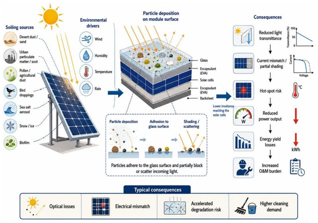
Figure 2.
Classification of selfcleaning technologies for PV.
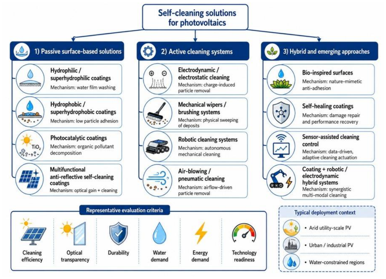
Figure 3.
Comparison of operating principles of hydrophilic and superhydrophobic selfcleaning surfaces.
Figure 3.
Comparison of operating principles of hydrophilic and superhydrophobic selfcleaning surfaces.
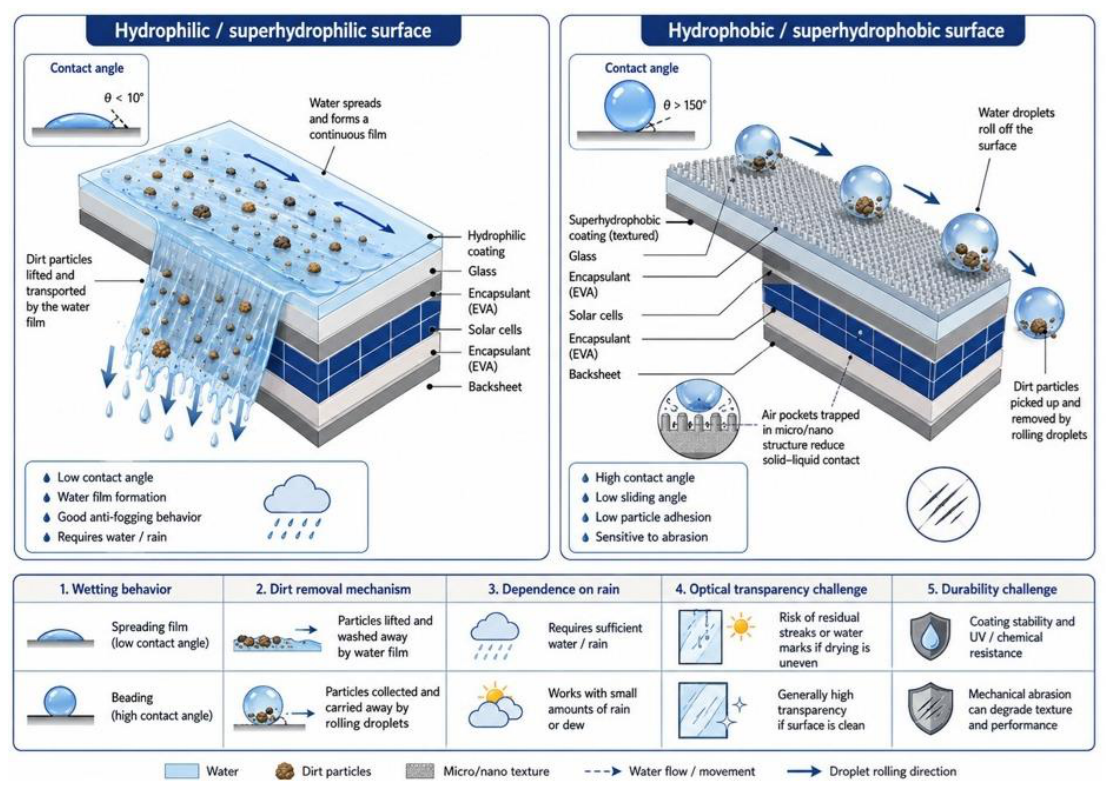
Figure 4.
Technology selection map for selfcleaning solutions in PV.
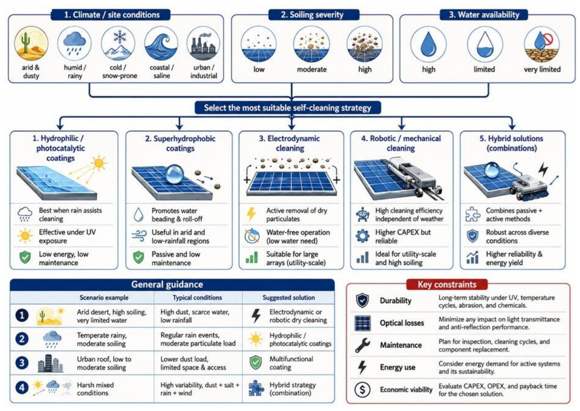

Table 1.
Number of publications, with associated citations, discussing the self-cleaning coatings for photovoltaics published from 2007 to 2025 (based on Web of Science data).
Table 1.
Number of publications, with associated citations, discussing the self-cleaning coatings for photovoltaics published from 2007 to 2025 (based on Web of Science data).
| Year |
Self-Cleaning Coatings for Photovoltaics |
Durability of Self-Cleaning Coatings for Photovoltaics | ||
| Publications | Citations | Publications | Citations | |
| 2007 | 2 | 4 | 0 | 0 |
| 2008 | 1 | 15 | 0 | 0 |
| 2009 | 0 | 11 | 0 | 0 |
| 2010 | 2 | 18 | 0 | 0 |
| 2011 | 0 | 16 | 0 | 0 |
| 2012 | 0 | 12 | 0 | 0 |
| 2013 | 4 | 18 | 0 | 0 |
| 2014 | 6 | 26 | 2 | 1 |
| 2015 | 1 | 42 | 0 | 0 |
| 2016 | 2 | 51 | 0 | 0 |
| 2017 | 4 | 63 | 0 | 0 |
| 2018 | 6 | 74 | 0 | 0 |
| 2019 | 3 | 119 | 0 | 0 |
| 2020 | 6 | 131 | 1 | 2 |
| 2021 | 6 | 173 | 0 | 3 |
| 2022 | 7 | 201 | 0 | 6 |
| 2023 | 10 | 181 | 2 | 1 |
| 2024 | 6 | 269 | 3 | 12 |
| 2025 | 10 | 346 | 2 | 38 |
Table 2.
Environmental factors in the soiling of PV modules.
| Country / Region |
Typical Soiling Characteristics |
Indicative Annual PV Energy Loss | Notes | Ref |
| China | Highly variable: urban smog and industrial dust, desert dust in the north and northwest, monsoon rainfall in the south | 3–10%, locally higher |
Losses are higher in dry, dusty and industrial regions, and lower in humid southern areas. | [22] |
| India and Pakistan | Mineral dust, soot, urban pollution, long dry pre-monsoon periods | 5–15%, seasonally >20% |
One of the most soiling-sensitive PV markets due to high particulate pollution and long dry periods. Monsoon rainfall can partly reduce seasonal accumulation | [23] |
| Saudi Arabia, Qatar United Arab Emirates / Oman / Kuwait / Bahrain, Iran | Desert dust, sandstorms salt aerosols, long dry periods, very low rainfall | 10–25%, temporarily >30% |
Soiling is a major operational issue; cleaning frequency strongly affects annual energy yield. Coastal-desert conditions combine mineral dust and salt deposition. | [24,25,26] |
| Japan | Frequent rainfall, marine aerosols, pollen, urban pollution, local snow impact | 1–4% | Rainfall limits annual dust accumulation, but pollen, salt spray and low-tilt rooftops can still matter. | 1 |
| South Korea | Urban pollution, Asian dust events, seasonal rainfall | 2–6% | Moderate soiling risk driven by urban pollution and long-range transported dust. | [27] |
| Mongolia / northern China / Kazakhstan | Steppe and desert dust, dry windy periods, local snow impact | 5–15% | Wind can both remove and deposit dust; low rainfall increases persistent soiling risk. | [18] |
| Thailand, Malaysia, Indonesia, Philippines, Vietnam | Tropical climate, monsoon rainfall, urban and agricultural dust, seasonal biomass burning | 2–8% | Losses may increase during the dry season and in agricultural or polluted areas. Rainfall reduces mineral dust, but biofilm, organic deposits and edge soiling can remain problematic | [24] |
| Norway, Sweden, Finland, Denmark, Baltic states | Low dust deposition, frequent precipitation, snow in winter | 0.2–2% | Among the lowest values in Europe; losses are mainly limited by rainfall and low airborne dust. local agricultural dust and salt spray may increase losses | [28] |
| United Kingdom, Ireland, Ger-many, Poland, Czech Republic, Slovakia, Netherlands, Belgium, Luxembourg, France | Frequent rainfall, marine aerosols, urban pollution, biological growth | 0.5–5% | Low annual mineral-dust soiling, but organic growth and edge deposits can be relevant on low-tilt systems. Central European losses are typically moderate and more evenly distributed across the year than in southern Europe. | [25] |
| Spain, Portugal, Greece, Malta, Cyprus | Dry summers, mineral dust, Saharan dust events, agricultural dust | 3–14%, locally higher |
One of Europe’s higher-risk countries; the European assessment found maximum losses of around 14% in Spain under low rain-cleaning effectiveness. Northern Italy is more influenced by urban/industrial aerosols; southern Italy by dry periods and Saharan dust. | [25] |
| Bulgaria / Romania, Hungary, Croatia, Slovenia, Serbia, Bosnia and Herzegovina, North Macedonia, Albania, Montenegro | Mixed coastal and inland conditions, agricultural dust, urban pollution, summer dry periods | 1–7% | Moderate losses; higher values expected in dry agricultural regions and low-tilt arrays. Coastal salt aerosols and summer dryness can increase local soiling. | [25] |
Table 3.
Most commonly used methods for producing self-cleaning coatings on photovoltaic modules.
| Manufacturing method | Coating creation process / typical materials | Characteristics of the resulting coating | Main advantages | Limitations | Ref |
| Sol–gel + dip-coating | Hydrolysis and condensation of precursors, such as alkoxysilanes or alkoxytitanates. The resulting SiO₂, TiO₂, or SiO₂/TiO₂ sol is applied to the glass via immersion followed by controlled withdrawal, after which it is dried and often heat-treated. | Widely used for hydrophilic/photocatalytic TiO₂ coatings, anti-reflective SiO₂ coatings, and multilayer systems. The thickness depends, among other factors, on the sol concentration and the withdrawal speed. | Simple equipment; low cost; good control over composition; capability to coat relatively large surfaces; easy creation of multifunctional coatings (e.g., anti-reflective + self-cleaning). | A relatively long process; the need for drying/curing; the potential for cracks, pores, and non-uniform thickness to develop; and the consumption of a large amount of solution when dealing with large components. | [100] |
| Sol–gel + spin-coating | A small amount of sol is applied to the centre of a piece of glass, which is then rotated at high speed; centrifugal force spreads the material into a thin layer. Typically, this involves TiO₂, SiO₂, ZnO, or nanocomposites. | It allows for the production of very thin, relatively uniform layers. It is particularly popular in laboratory research. | Good control of thickness and uniformity; ease of obtaining nanometric coatings; reproducibility; small amount of material remaining on the sample. | Not well-suited for full-scale PV modules; material loss during the spin-coating process; difficulties with industrial-scale implementation; limitations imposed by the size of the equipment. | [108] |
| Spray-coating | A suspension containing nanoparticles (e.g., SiO₂, TiO₂, ZnO) and a polymer or siloxane (e.g., PDMS) is sprayed onto glass, followed by drying or thermal/UV curing. | Particularly suitable for hydrophobic and superhydrophobic coatings. Nanoparticles create a micro-/nanostructure that increases roughness, while compounds with low surface energy provide hydrophobicity. | Very good scalability; low equipment costs; rapid coverage of large surface areas; possibility of application onto existing modules; good industrial prospects. | More difficult control of uniformity and thickness compared to vacuum techniques; nanoparticle aggregation; reduced transmission due to excessive roughness; mechanical durability may be limited. | [111] |
| Spray pyrolysis | The precursor solution is sprayed onto heated glass, where the droplets evaporate and the precursor decomposes, forming an oxide layer, such as TiO₂, ZnO, or SnO₂. | It enables the formation of crystalline oxide layers with little or no subsequent annealing. The coatings can exhibit hydrophilicity and photocatalytic activity. | A relatively inexpensive process; no need for a high vacuum; capability to coat large surface areas; easy doping of layers. | High substrate temperature; more difficult control of nanostructure and uniformity; spraying parameters have a strong influence on transparency and porosity. | [100] |
| Chemical Vapour Deposition – CVD / APCVD | Volatile precursors react or decompose on a heated glass surface, forming a thin film—most commonly TiO₂ or multi-oxide systems. APCVD is carried out at atmospheric pressure. | Highly uniform and dense layers, typically with strong adhesion. TiO₂ provides photocatalysis and photo-induced hydrophilicity. | High durability; good adhesion; suitability for a continuous industrial process during glass manufacturing; high repeatability. | Higher installation cost; elevated temperature; use of reactive precursors; more difficult optimization of the process and composition; greater complexity compared to sol–gel/spray methods. | [56] |
| Magnetron sputtering (PVD) | Plasma ions bombard a target—for example, Ti or TiO₂—and the ejected atoms are deposited onto the glass. The process can be reactive in the presence of O₂; subsequent annealing is often employed. | Very thin, dense layers with strong adhesion to the substrate. Precise control over thickness, composition, and optical properties is possible. | Very high quality and uniformity; good adhesion; precise thickness control; capability to produce multilayers and photocatalytic layers with high transmission. | Expensive vacuum equipment; higher production costs; baking-out often required. | [136] |
| Layer-by-Layer – | The glass is brought into contact, in sequence, with solutions of substances possessing opposite charges or functionalities. A layer is built up sequentially using polyelectrolytes and nanoparticles, such as SiO₂. Subsequently, calcination and hydrophobic modification can be performed. | Excellent control of structure at the nanometric level. It is possible to combine anti-reflectivity, appropriate roughness, and hydrophobicity. | Precise control over thickness and porosity; easy creation of multifunctional coatings; good control over optical properties. | A multi-stage and time-consuming process; involves multiple application/rinsing cycles; more difficult to scale up for large PV surfaces compared to spray coating. | [137] |
| Plasma processing / deposition | The surface is activated by plasma, or a layer is deposited from the gas phase via a plasma-assisted process. It is possible to apply oxides or modify the surface energy of the glass. | It allows for the simultaneous control of surface chemistry and morphology; thin hydrophilic or hydrophobic coatings can be applied. | Good adhesion; low consumption of reagents; capability for rapid processing; atmospheric plasma processes can be adapted for continuous production lines. | Cost of equipment; sensitivity to process parameters; less common in PV than sol–gel or spraying; necessity of ensuring uniformity over a large area. | [15] |
Table 4.
Example criteria for evaluating self-cleaning coatings.
| Parameter | Proposed criterion after aging |
| Wetting angle of the superhydrophobic coating | ≥150° |
| Sliding angle | ≤10° |
| Loss of spectrally weighted transmission | ≤1 percentage point |
| Retention of self-cleaning efficiency | ≥80% of the initial value |
| Coating delamination | No visible detachment |
| Surface damage | No optically significant damage |
Table 5.
Summary of key progress achieved and research gaps in the main areas of study.
| Research Area | Key Progress Achieved | Major Research Gap |
| Hydrophobicity and Hydrophilicity | Wettability control via nanostructure and surface chemistry | Retention of properties after aging |
| Transparency | Development of porous and nanostructured coatings with low optical losses | Simultaneous optimization of transmission, durability, and self-cleaning |
| Multifunctionality | Integration of self-cleaning with anti-reflectivity and condensation mitigation | Durable combination of all functions |
| Particle Adhesion | Determination of the influence of humidity, capillary bridges, and cementation | Quantitative models for real-world dust mixtures |
| Decision-Making Models | Development of economic, predictive, and AI-based methods | Integration of coating parameters with operational decision-making |
Table 5.
Main operating mechanisms of self-cleaning coatings and their limitations.
| Type of coating | Self-cleaning mechanism | Key limitations |
| Superhydrophobic | Water droplets move easily across the surface, carrying away dirt particles | Damage to the micro- and nanostructure, loss of hydrophobicity, low effectiveness against strongly adhering deposits |
| Superhydrophilic | Water forms a film that facilitates the rinsing away of contaminants | Dependence on the presence of water, potential for leaving behind mineral deposits |
| Photocatalytic (e.g., TiO₂) | Photodegradation of specific organic contaminants upon exposure to radiation | Limited effectiveness against mineral dust, dependence on the radiation spectrum, potential degradation of adjacent organic materials |
| Hybrid | Combination of several mechanisms, e.g., hydrophobicity and anti-reflective properties | Technological complexity, greater difficulty in ensuring the stability of all functions simultaneously |
Disclaimer/Publisher’s Note: The statements, opinions and data contained in all publications are solely those of the individual author(s) and contributor(s) and not of MDPI and/or the editor(s). MDPI and/or the editor(s) disclaim responsibility for any injury to people or property resulting from any ideas, methods, instructions or products referred to in the content. |
© 2026 by the authors. Licensee MDPI, Basel, Switzerland. This article is an open access article distributed under the terms and conditions of the Creative Commons Attribution (CC BY) license.
Copyright: This open access article is published under a Creative Commons CC BY 4.0 license, which permit the free download, distribution, and reuse, provided that the author and preprint are cited in any reuse.