

Submitted:
16 November 2026
Posted:
17 November 2026
You are already at the latest version
Abstract
Interrupted-sampling repeater jamming (ISRJ) produces dense, extended, and migrated false targets that compromise radar detection. Existing suppression methods often require accurate jamming priors or use single-domain features and hard decisions, risking genuine-target loss. We propose a jointly optimized random interpulse frequency and intrapulse phase-coded linear frequency-modulated (RIF-PCLFM) waveform with dual-domain recognition and target-protective suppression. Intrapulse phases and interpulse frequency ordering are jointly optimized under constant-modulus, fixed-bandwidth, and invariant-frequency-set constraints to reduce range sidelobes, off-axis range–Doppler leakage, and residual coupling. An exact nonuniform discrete Fourier transform preserves coherent integration for frequency-hopped pulses. Multichannel one-shot phase compensation refocuses ISRJ responses while distinguishing genuine targets coherent in the zero-compensation channel. Uncertain or temporally aliased candidates undergo decoded-range-profile analysis using peak count and mainlobe width; a guarded mismatched decoder reduces local sidelobes without erasing the main peak. Range–Doppler reconstruction and decoded-domain structural confidence are fused into a soft suppression mask that protects target energy. Simulations involving interrupted-sampling direct, repetitive, and cyclic repeater jamming demonstrate reduced range–Doppler coupling, sparse false-target reconstruction, and reliable recognition and suppression across input signal-to-interference and signal-to-noise conditions, balancing residual interference, target preservation, and online complexity.
Keywords:
dual-domain recognition
; interrupted-sampling repeater jamming
; joint intrapulse–interpulse optimization
; radar electronic counter-countermeasures
; RIF-PCLFM waveform
; target-protective soft suppression
1. Introduction
Pulse-Doppler (PD) radar is widely used for the detection and tracking of high-speed targets because it provides two-dimensional range–velocity resolution and coherent integration gain. However, advances in digital radio-frequency memory (DRFM) technology have substantially improved the replication accuracy, response speed, and modulation flexibility of coherent deception jammers, creating complex electromagnetic environments in which genuine and false echoes are highly coherent and their spatial, temporal, and spectral features are strongly coupled [1,2]. Interrupted-sampling repeater jamming (ISRJ) periodically intercepts, stores, and retransmits segments of a radar pulse. After pulse compression, these segments can produce dense false targets with partial processing gain, while direct, repetitive, and cyclic retransmission strategies can simultaneously exert deception and suppression effects [3,4,5]. When multiple jammers, retransmitted components, or retransmission modes coexist, false targets become aliased in range, frequency, and Doppler, further complicating weak-target detection, jamming recognition, and target-parameter estimation.
Existing ISRJ-suppression studies can generally be classified into three categories: joint transmit-waveform and receive-filter design, jamming-parameter estimation followed by reconstruction and cancellation, and multidomain feature separation. Joint-design methods construct detection waveforms, decoy waveforms, complementary sequences, or mismatched filters to reduce the correlation between intercepted segments and useful echoes [6,7,8]. Reconstruction-and-cancellation methods recover jamming components from parameters such as the sampling period, sampling width, and retransmission delay and then suppress them through mismatched filtering or sparse reconstruction [9,10]. Waveform-domain adaptive matched filtering and complementary signal-set methods further exploit differences in the correlation structures of jamming and target echoes to improve the output signal-to-interference ratio (SIR) [11,12]. Although these approaches can be effective in specific scenarios, most require accurate jamming priors or parameter estimates. When composite ISRJ exhibits temporal aliasing, parameter mismatch, or pulse-to-pulse structural variation, estimation errors can be amplified by subsequent reconstruction and filtering. Moreover, directly nulling suspected jamming cells or applying fixed-depth suppression may cause pronounced target-energy loss when genuine and false targets are adjacent or overlapping.
Reliable discrimination between genuine targets and ISRJ false targets is a prerequisite for robust suppression. Time-domain methods typically construct decision statistics from the intermittency and coherent-integration decomposition characteristics of ISRJ [13]. Time-frequency methods use the short-time Fourier transform, fractional Fourier transform, or multidimensional filtering to extract differences in energy intermittency, chirp rate, and frequency shift [14,15]. Clustering and deep-learning methods exploit data-driven representations to recognize jamming types or recover target locations [16,17]. Nevertheless, time-domain and time-frequency features degrade under low signal-to-noise ratio (SNR), strong sidelobe masking, and multi-jammer aliasing, while deep networks require large training sets, may generalize poorly across scenarios, and impose substantial online computational cost. Consequently, a single processing domain or a single decision threshold generally cannot simultaneously ensure recognition accuracy, real-time operation, and weak-target protection.
Phase-coded linear frequency modulation (PC-LFM) combines the large time-bandwidth product of LFM with the high degrees of freedom of phase coding. It can shape the autocorrelation function and ambiguity function while preserving range resolution and constant-envelope transmission, thereby providing additional design freedom for active electronic counter-countermeasures [18]. For the nonconvex optimization of constant-modulus sequences and transmit–receive filters, Riemannian-manifold methods iterate directly over complex-circle or complex-sphere constraint sets and avoid the feasibility-recovery errors introduced by conventional relaxations; these methods have been applied to radar-waveform, receive-filter, and ambiguity-function design [19,20]. Phase-coded signal-processing studies have shown that genuine targets and ISRJ false targets exhibit exploitable differences in the number, spacing, and mainlobe widths of peaks in decoded range profiles [21]. The subsequent PCLFM-R and M-PCLFM-R methods improve the recognition of periodic composite ISRJ by optimizing PC-LFM autocorrelation sidelobes and designing mismatched decoding filters [23]. However, these methods mainly exploit intrapulse decoding structures and do not fully use interpulse coding to regulate slow-time coherence and range–Doppler distributions.
To confine ISRJ to more readily separable range–Doppler (RD) regions, random interpulse frequency-coded LFM waveforms use random residual phase at nonzero delays to reduce the coherent integration of false targets and employ phase compensation to reconstruct the jamming [22]. Building on this idea, the RIF-PCLFM waveform combines random interpulse frequency coding with intrapulse phase coding. It preserves the range resolution of LFM while weakening range–Doppler coupling, thereby converting the extended or migrated ISRJ responses observed with conventional LFM into relatively sparse RD-domain false targets that can be recognized and suppressed through multichannel one-shot phase compensation [24]. More recently, learning-enhanced Riemannian transmit–receive joint design, multidimensional filtering, joint jamming perception and transmit-waveform design, and robust waveform optimization under inaccurate priors have further improved ISRJ countermeasure performance [25]–[28]. Nevertheless, the following issues have rarely been addressed simultaneously: intrapulse range sidelobes and interpulse off-axis RD leakage are not optimized within a unified formulation; nonuniform slow-time coherent integration caused by random frequency coding is not tightly integrated with composite-ISRJ recognition; RD-domain reconstruction criteria and decoded-range-profile structural criteria are not fused at the confidence level; and hard-decision suppression may still damage genuine targets when they are close to or overlap false targets.
To address these limitations, this article develops a jointly optimized intrapulse–interpulse RIF-PCLFM waveform and a dual-domain recognition and suppression method for composite ISRJ. The main contributions are as follows.
1) A joint optimization model is established for the intrapulse phase code and interpulse frequency code. Under constant-modulus, fixed-bandwidth, and invariant-frequency-set constraints, the model jointly controls the peak range sidelobe, range-sidelobe energy, off-axis RD peak, and residual coupling leakage. Componentwise degradation constraints prevent an improvement in one metric from severely degrading another processing domain.
2) For the nonuniform slow-time sampling nodes induced by frequency hopping, a coherent-integration and multichannel one-shot phase-compensation procedure is developed. It exploits the recoverability of the ISRJ residual phase and the fact that a genuine target remains coherent only in the zero-compensation channel to provide RD-domain coarse decisions and false-target reconstruction evidence.
3) For candidates with uncertain coarse decisions or severe temporal aliasing, PCLFM-R extracts the peak-count and mainlobe-width features. An M-PCLFM-R mismatched decoder with a main-peak guard constraint is further designed to reduce local integrated sidelobes while retaining the candidate main peak and its discriminative structure.
4) The RD-domain reconstruction probability and decoded-domain structural probability are fused to construct a target-protective soft suppression mask. The suppression depth is adjusted continuously according to the jamming confidence and target evidence, providing a balance among composite-ISRJ suppression, genuine-target preservation, and online complexity.
The remainder of this article is organized as follows. Section II presents the RIF-PCLFM signal model, joint intrapulse–interpulse waveform optimization, nonuniform slow-time coherent integration, RD-domain coarse estimation, decoded-domain fine discrimination, and dual-domain soft suppression. Section III evaluates waveform optimization, recognition and suppression, and target preservation through simulations. Section IV concludes the article.
2. Joint RIF-PCLFM Recognition and Suppression of ISRJ
2.1. Overall Processing Framework
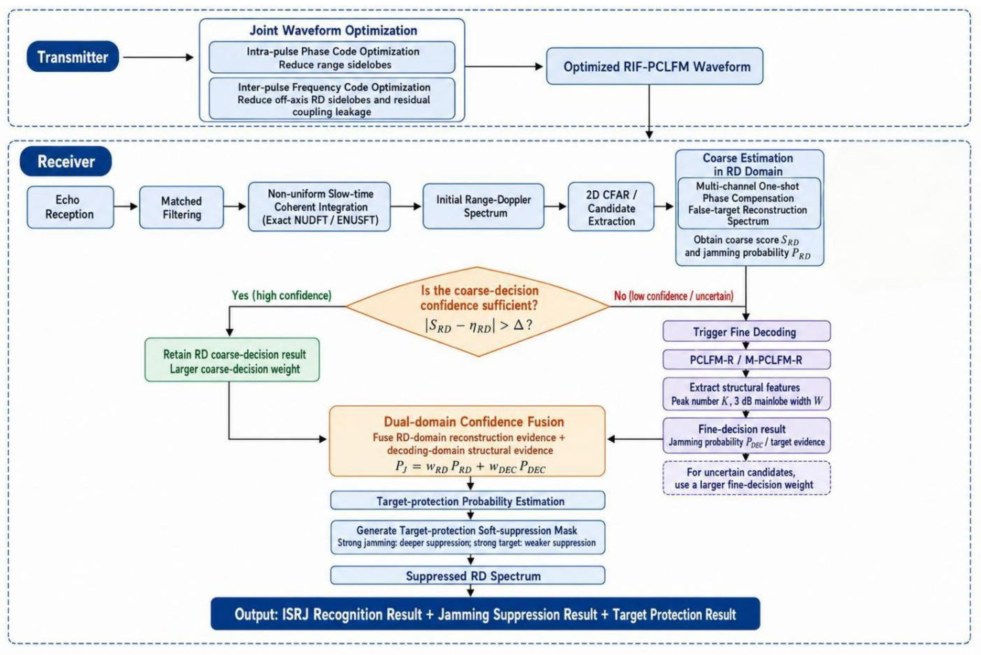
For ISRJ recognition and suppression under joint random interpulse frequency coding and intrapulse phase coding, a hierarchical framework is constructed comprising joint waveform optimization, nonuniform slow-time coherent integration, RD-domain coarse estimation, decoded-domain fine discrimination, dual-domain confidence fusion, and target-protective soft suppression.
At the transmitter, the intrapulse phase code and interpulse frequency code are first jointly optimized to reduce range sidelobes, off-axis RD sidelobes, and residual coupling leakage while preserving the constant modulus, total bandwidth, and frequency set. At the receiver, matched filtering is applied pulse by pulse, and coherent integration is performed at the nonuniform slow-time nodes produced by interpulse frequency hopping to obtain the initial RD spectrum. The random-frequency residual phase of an ISRJ false target can then be refocused by phase compensation, whereas a genuine target remains coherent only in the zero additional-compensation channel. This distinction is used to construct a multichannel one-shot phase-compensated false-target reconstruction spectrum. Candidates with insufficient coarse-decision confidence are further decoded locally by PCLFM-R or M-PCLFM-R to extract the peak count and mainlobe width. Finally, the RD-domain reconstruction evidence and decoded-domain structural evidence are fused to form a target-protective soft suppression mask.
Figure 1.
Overall processing framework of the proposed method.
2.2. RIF-PCLFM Signal Model and Ambiguity-Function Characteristics
Consider a coherent processing interval (CPI) containing Np pulses, each of which consists of M phase chips. The pulse width, pulse repetition interval, and chip width are denoted by T, Tr, and Tc = T/M, respectively. The LFM bandwidth and chirp rate are B and K = B/T; the carrier frequency is fc; and the frequency hop of the nth pulse is fn. The fast-time sampling rate and sampling interval at the receiver are Fs and Ts = 1/Fs. The interrupted-sampling period, sampling width, and sampling repetition frequency of the jammer are denoted by Tu, TJ, and fs,J = 1/Tu, respectively.
2.2.1. Transmitted Signal Model
The mth intrapulse phase chip is defined as
The baseband RIF-PCLFM signal of the nth pulse is expressed as
The transmitted signal over one CPI is
The phase-coded term in (2) disrupts the range–Doppler coupling of a conventional LFM waveform under nonzero chip misalignment, whereas the interpulse frequency-coded term reduces the slow-time coherent gain at nonzero delays. Because the phase code satisfies a constant-modulus constraint, the joint coding does not alter the envelope power of an individual pulse.
2.2.2. CPI Ambiguity-Function Decomposition
The signal ambiguity function is defined as
For delays shorter than one pulse repetition interval and neglecting cross terms between different pulses, the CPI ambiguity function can be approximated as
where is the single-pulse PC-LFM ambiguity function. Equation (5) shows that the RIF-PCLFM ambiguity function is jointly determined by the intrapulse PC-LFM correlation structure and the interpulse random-frequency slow-time coherence factor.
Let
where g is the chip-offset index. When g ≠ 0, the single-pulse correlation term contains
For conventional LFM, the ambiguity function forms a strong coupling ridge near . In contrast, the nonuniform interchip phases in (7) disrupt coherent summation along this ridge. Therefore, when , PC-LFM phase coding can substantially weaken range–Doppler coupling.
Define the interpulse coherence factor as
When , the range-dependent phase introduced by frequency hopping vanishes, and a genuine target retains the normal slow-time coherent integration gain. When , varies from pulse to pulse, causing the nonzero-delay response to approach incoherent accumulation. Thus, phase coding breaks the LFM coupling beyond one chip width, whereas random or optimized frequency coding whitens the slow-time response at nonzero delays.
2.3. Joint Intrapulse–Interpulse Waveform Optimization
2.3.1. Intrapulse Phase-Code Optimization
The actual LFM phases at the chip centers form the reference vector
The phase-code vector is denoted by
The equivalent signal sampled at the chip centers is
Define the positive-delay shift matrix whose elements satisfyJk
The kth aperiodic autocorrelation sidelobe is
where
To jointly control the peak sidelobe and integrated sidelobe energy, the following hybrid objective is constructed:
subject to
where the high-order Lp norm approximates the maximum sidelobe and the L2 norm reduces the overall sidelobe energy. For a general sidelobe Lq norm,
the Euclidean gradient is
The constant-modulus constraint defines the complex-circle manifold
Projecting the Euclidean gradient onto the tangent space of the complex-circle manifold gives the Riemannian gradient
After updating along the negative-gradient direction, elementwise normalization retracts the iterate to the unit circle:
The step size is determined by backtracking line search to ensure a monotonic decrease of the objective function.
2.3.2. Interpulse Frequency-Code Optimization
On a discrete delay–Doppler grid, define the two-dimensional response of the frequency code as
where wl is determined by the correlation magnitude of the intrapulse PC-LFM waveform at the corresponding chip delay. To prevent the zero-Doppler principal axis shared by all waveforms from dominating the optimization, define the off-axis region
where is the Doppler guard width. The off-axis peak and energy metrics are, respectively,
The frequency-code objective is
The frequency code must remain a permutation of the prescribed frequency set ; therefore, a random-swap search is adopted. Two pulse positions, i and j, are selected at random, and
The swap is accepted when Jf(f+)<Jf(f); otherwise, the current frequency permutation is retained. This strategy optimizes the interpulse ordering without changing the frequency set, total hopping bandwidth, or number of uses of each frequency.
2.3.3. Joint Intrapulse–Interpulse Optimization
Define the following four physical metrics:
where Pr and Er denote the peak range sidelobe and the root-mean-square (RMS) range sidelobe, respectively, while PRD and ERD denote the off-axis RD peak and off-axis RD leakage energy. Reference scales si are constructed from the best individual values among several available initializations, and the joint objective is
together with the componentwise degradation constraints
The joint optimization alternates between small-angle perturbations of an individual phase chip and swaps of two pulse-frequency positions. A candidate is accepted only if it satisfies (24) and decreases (23). These constraints prevent a substantial sacrifice in one domain merely to obtain a local improvement in another.
2.4. Formation Mechanisms of Target and ISRJ Echoes
2.4.1. Moving-Target Echo
For a target at range RT, the round-trip delay is
For a target with radial velocity vT, the Doppler frequency of the nth frequency-hopped pulse is
Neglecting higher-order motion terms, the target baseband echo of the nth pulse is
where is the complex target amplitude and is the range-dependent phase introduced by interpulse frequency hopping.
2.4.2. Periodic Interrupted Sampling and False-Target Locations
The periodic interrupted-sampling gate is expressed as
Its Fourier series is
where
If the jammer imposes an additional frequency shift fJ, the total frequency shift of the lth spectral component is
Let the reference delay of the qth retransmission be . Because of LFM range–frequency coupling, the delay of the (q,l)th potential false target is
Let
Then . For an RIF-PCLFM signal, when , intrapulse phase-code misalignment substantially suppresses the corresponding component; when , the interpulse random-frequency term destroys its slow-time coherence. Consequently, the widely extended and migrated false targets produced by conventional LFM are confined to a finite set of sparse responses under RIF-PCLFM transmission.
2.5. Nonuniform Slow-Time Coherent Integration
From (26), the slow-time phase of the nth pulse can be expanded as
This motivates the following nonuniform slow-time nodes:
At range gate , the range-dependent phase introduced by interpulse frequency hopping is first compensated as
A nonuniform DFT is then performed over the Doppler grid :
In matrix form,
Equation (37) is the exact nonuniform DFT (NUDFT) formulation.
2.6. RD-Domain Coarse Estimation by Multichannel One-Shot Phase Compensation
2.6.1. False-Target Phase-Refocusing Principle
The slow-time steering vector of a false target at offset is
Construct the compensation vector
which yields
Equation (41) shows that an ISRJ false target defocused by random frequency coding can recover a linear slow-time phase after phase compensation. By contrast, a genuine target at the correct range gate has already undergone range-phase compensation and remains coherent only in the zero additional-compensation channel; nonzero compensation channels instead whiten it through the frequency code.
2.6.2. Discrete Multichannel Compensation
Let the fast-time sampling interval be Ts. The number of samples corresponding to one chip width is
Construct the compensation-delay set
and the compensation matrix
To prevent a genuine target from entering the false-target reconstruction spectrum through the zero-compensation channel, set
A two-dimensional constant false-alarm rate (CFAR) detector is applied to the initial RD spectrum to obtain the candidate range-gate set . For each candidate, only the following local source range gates are processed:
Let the slow-time vector at source range gate i be yi. The multichannel compensation output is
For the kth compensation channel, nonuniform slow-time coherent integration is performed as
The compensation delay corresponds to a shift of k fast-time samples in the range coordinate; hence, the reconstruction spectrum is updated as
The final false-target reconstruction spectrum is
2.6.3. Coarse-Decision Statistic and Uncertainty Trigger
Normalize the reconstruction spectrum as
The coarse-decision score around the hth candidate is defined as
where is the local RD neighborhood of the candidate. A threshold is used for the preliminary decision:
Following the RIF-PCLFM method, is used. To reduce decision fluctuations near a fixed threshold, define the uncertainty interval
M-PCLFM-R fine decoding is triggered only for candidates satisfying (54). Candidates far from the threshold directly retain the RD-domain coarse decision, thereby balancing recognition accuracy and computational efficiency.
2.7. PCLFM-R Fine Candidate Decoding and Structural Feature Extraction
2.7.1. Decoded Range Profile of a Genuine Target
Let the candidate delay be . The local fast-time echo associated with the candidate is extracted, dechirped, and multiplied by the conjugate phase code aligned with the candidate position:
When the candidate corresponds to a genuine target, the phase code is completely removed and the decoded signal reduces to a finite-duration single-frequency signal:
Its spectrum is
Therefore, the decoded range profile of a genuine target contains a single sinc-shaped peak with the nominal mainlobe width.
2.7.2. Multipeak and Broadening Features of ISRJ
For ISDRJ or an individual ISRRJ false target, the decoded interrupted-gate signal can be approximated as
Its spectrum contains multiple sinc components separated by 1/Tu; therefore, the peak spacing in the decoded range profile is
For ISCRJ, the effective duration of the mth retransmitted component is approximately
and the corresponding mainlobe width of the range profile is approximately
As the number of retransmissions increases, the effective duration decreases and the mainlobe gradually broadens. Thus, ISRJ mainly exhibits either multiple peaks with approximately fixed spacing or a single peak with pronounced broadening in the decoded range profile.
2.7.3. Peak-Count and Mainlobe-Width Decision
Let Npk be the number of valid peaks obtained after ordered-statistic CFAR (OS-CFAR) processing of the decoded range profile, and let W3dB be the 3-dB width of the main peak. The theoretical full 3-dB mainlobe width of an ideal target is approximately
The candidate-decision rule is
where is a width-tolerance factor accounting for windowing, discrete sampling, and noise.
2.8. M-PCLFM-R Mismatched Decoding Filter
2.8.1. Modeling of Temporally Aliased Candidates
Conventional PCLFM-R is affected by the cross-correlation of adjacent candidates under severe temporal aliasing. Let the delay of the current candidate be , the delay of the jth neighboring candidate be , and their discrete sample offset be
After removing the common LFM phase, the relative beat frequency between the two candidates is
Let be a zero-padded shift matrix and be the complex-amplitude ratio between a neighboring candidate and the current candidate. The equivalent code vector formed by all temporally aliased candidates is
2.8.2. Local Integrated-Sidelobe Minimization
Let the mismatched decoder to be designed be wu. The decoded fast-time vector is
Let F denote the discrete Fourier transform matrix. The decoded range profile is
Select the sidelobe region to be suppressed on both sides of the candidate center while excluding the theoretical mainlobe interval. The corresponding rows of the Fourier matrix form
The local integrated sidelobe energy is
The mismatched-filter optimization problem is formulated as
where Ns = TFs is the number of fast-time samples in one pulse. After normalizing , the constraint becomes the complex sphere . The Euclidean gradient is
The Riemannian gradient on the complex sphere is
After updating along a Riemannian conjugate direction, the iterate is retracted through
to the complex sphere.
2.8.3. Main-Peak guaRD Constraint
Minimizing only (70) may suppress both the sidelobes and the candidate main peak. To preserve the discriminative features, introduce the target-matched direction a and impose the following lower bound on the main-peak response:
The robust mismatched-filter problem is therefore
where , and Lpk is the maximum allowable main-peak loss in decibels. This constraint reduces the integrated sidelobes around the candidate while limiting main-peak attenuation.
2.9. Dual-Domain Confidence Fusion and Target-Protective Soft Suppression
2.9.1. Fusion of Coarse- and Fine-Decision Confidence
The RD-domain coarse-decision score is mapped to a jamming probability through a sigmoid function:
The fine-decision probability is defined from the PCLFM-R or M-PCLFM-R result as
The fused dual-domain jamming probability is
A larger coarse-decision weight wc,u is used for candidates far from the threshold and therefore having low uncertainty. For uncertain candidates satisfying (54), a larger fine-decision weight wf,u is used. The target-protection probability is further defined from the fine-decision result as
where eT,u is the target-structure evidence coefficient.
2.9.2. Target-Protective Soft Suppression
Assume that the uth candidate is located at RD cell (du,ru). A two-dimensional local Gaussian kernel is constructed as
The effective jamming probability after target protection is
When a candidate has strong target evidence, PT,u increases and (82) automatically reduces the suppression depth. When the jamming evidence is strong and the target evidence is weak, the suppression depth approaches PJ,u. The soft masks generated by multiple candidates are combined by taking the local maximum:
The suppressed RD spectrum is finally
Unlike direct nulling of RD cells classified as jamming, (84) continuously adjusts the suppression depth according to the dual-domain confidence and reduces target loss when a genuine target and ISRJ occupy the same or adjacent RD cells.
2.10. Mathematical Closure and Applicability Conditions
The complete method can be summarized as
To prevent appreciable range migration of a genuine target after intrapulse processing, the following condition should hold:
To ensure that the principal ISRJ spectral components lie within the compensable interval of one phase chip, the following condition is required:
For dominant harmonics without an additional frequency shift, the approximate parameter constraint is
In summary, the proposed method establishes complementary evidence through transmit-waveform structural constraints, RD-domain reconstructability, and decoded-range-profile structures. An uncertainty-trigger mechanism restricts the high-complexity mismatched filtering to a small number of candidates, thereby balancing recognition accuracy, suppression performance, target protection, and online computational cost.
3. Simulation Results and Analysis
The proposed jointly optimized intrapulse–interpulse RIF-PCLFM waveform and dual-domain recognition and suppression method are evaluated from six perspectives: waveform optimization, ambiguity-function characteristics, nonuniform slow-time coherent integration, RD-domain false-target reconstruction, decoded-domain structural discrimination, and overall antijamming performance. Three representative forms of ISRJ are considered: interrupted-sampling direct repeater jamming (ISDRJ), interrupted-sampling repetitive repeater jamming (ISRRJ), and interrupted-sampling cyclic repeater jamming (ISCRJ). The comparison methods are PC-LFM-R, which uses only decoded-domain structural features; RIFC-LFM-RD, which uses only RD-domain multichannel phase compensation; and the proposed Joint RIF-PCLFM dual-domain fusion method. Except for the waveform-mechanism illustrations, all performance results are obtained from Monte Carlo trials with independent noise and random initial phases.
3.1. Simulation Parameters and Evaluation Metrics
The principal simulation parameters are listed in Table 1.
The primary recognition metric is the jamming-region recognition rate. The ground-truth jamming regions are first extracted from the noise-free RD spectrum, excluding the target-protection region. A region is considered successfully recognized if the recognition/suppression mask generated by the algorithm exceeds a prescribed threshold in the neighborhood of that region. The jamming-region recognition rate is defined as
where Nrec and Ntruth are the number of successfully recognized ground-truth jamming regions and the total number of ground-truth jamming regions, respectively.
Suppression performance is measured by the output SIR, defined as
where AT_out is the target-neighborhood peak after processing and AJ_out is the maximum residual-jamming peak outside the target-protection region.
3.2. Convergence and Ambiguity-Function Performance of the Joint Waveform Optimization
The convergence of the intrapulse phase code, interpulse frequency permutation, and their joint optimization is first examined. Figure 2(a) shows the hybrid sidelobe objective of the intrapulse phase code versus iteration. The objective decreases rapidly at the beginning and then gradually enters a steady convergence region, indicating that phase perturbations under the constant-modulus constraint continuously reduce the peak sidelobe and integrated sidelobe energy. In Figure 2(b), the off-axis RD objectives decrease in a staircase manner for both frequency-permutation-only optimization and joint initialization because a discrete swap is accepted only when it decreases the objective. Figure 2(c) further shows that, under the componentwise degradation constraints, the total objective, range peak, range RMS, off-axis peak, and off-axis RMS all exhibit overall decreasing trends. No domain is substantially sacrificed to obtain a local improvement in another.
To illustrate the effect of joint optimization on range–Doppler coupling and wideband sidelobes, Figure 3 compares LFM, random PC-LFM, phase-code-only optimized PC-LFM, and jointly optimized RIF-PCLFM waveforms. Slices along the LFM coupling ridge show that conventional LFM retains a strong response over a broad delay interval, producing a continuous coupling ridge. Adding the intrapulse phase code disrupts coherent summation at nonzero chip offsets and markedly reduces the ridge. Random frequency coding alone whitens part of the nonzero-delay response, but the range sidelobes and worst-case Doppler envelope still fluctuate considerably. The jointly optimized waveform yields lower non-mainlobe responses in the coupling-ridge slice, worst-case response envelope, and zero-Doppler range slice, confirming the complementary suppression mechanisms of intrapulse phase coding and interpulse frequency coding.
The two-dimensional ambiguity functions are shown in Figure 4. The LFM waveform exhibits the typical oblique range–Doppler coupling ridge. An additional jamming frequency shift is mapped into a range offset along this ridge, producing extended or migrated false targets. Random PC-LFM weakens the continuous coupling structure, but its two-dimensional sidelobe floor remains high and nonuniform. The jointly optimized RIF-PCLFM waveform retains a concentrated main peak, breaks the continuous ridge at nonzero delays, and compresses the sidelobe energy into low-amplitude sparse responses. This behavior provides the waveform basis for subsequent ISRJ reconstruction using local candidates and a finite number of compensation channels.
3.3. Numerical Validation of Nonuniform Slow-Time Coherent Integration
Interpulse frequency hopping displaces the equivalent slow-time nodes from a strictly uniform grid. If a conventional FFT is applied directly, the target slow-time phase is mismatched to the FFT basis, causing peak loss, sidelobe elevation, and even peak-location bias. Figure 5 compares Doppler focusing obtained by a conventional FFT and the exact NUDFT. The exact NUDFT produces a sharp main peak close to 0 dB at the true Doppler, whereas the conventional FFT exhibits a pronounced notch at the true Doppler and spreads the energy over several adjacent bins. The nonuniform slow-time nodes are therefore not a negligible perturbation; exact compensation is required to preserve coherent integration gain under random interpulse frequency coding.
3.4. RD Distributions, Reconstruction, and Suppression of Three ISRJ Types
Figure 6 shows the original RD spectra of ISDRJ, ISRRJ, and ISCRJ for different transmitted waveforms. Because of range–Doppler coupling, conventional LFM produces strong continuous bands or extended structures near the target for all three jamming types, and the genuine target is easily masked by false-target groups and a high sidelobe background. Random interpulse frequency-coded LFM destroys part of the false-target slow-time coherence but does not use intrapulse phase coding to suppress chip-offset coupling; pronounced range stripes therefore remain. The jointly optimized RIF-PCLFM waveform limits both intrapulse coupling and interpulse coherence, converting the continuously extended false targets into a finite number of sparse and reconstructable local responses for all three jamming types. Importantly, the raw jamming energy in the RIF-PCLFM RD spectrum is not necessarily the lowest. Its essential advantage is that it transforms the jamming into responses with discriminative phase structure, thereby enabling subsequent reconstruction and recognition.
The complete processing sequence after multichannel one-shot phase compensation at candidate range gates is shown in Figure 7. The first column presents the original RD spectra; the second shows the false-target reconstruction spectra obtained after searching neighboring source range gates, compensating residual delays, and remapping the coordinates; the third shows the local soft masks generated by fusing candidate jamming probabilities with target-protection evidence; and the fourth shows the suppressed RD spectra. For ISDRJ, the reconstructed energy is concentrated mainly in a single retransmission region. For ISRRJ, repeated retransmissions form several reconstructable regions in range. For ISCRJ, the different durations of the retransmitted components produce a nonuniform reconstruction distribution in range and Doppler. Although the spatial morphologies differ, multichannel compensation restores the slow-time coherence dispersed by random frequency coding in all three cases, making the reconstruction spectrum complementary to the original spectrum.
The soft mask does not simply null candidate cells. Instead, a two-dimensional Gaussian kernel is centered at each candidate, and the suppression depth is adjusted continuously according to the fused jamming probability. Regions with strong reconstruction evidence and weak target evidence receive deep suppression, whereas regions with strong target-structure evidence or locations near the genuine target receive a shallower mask. As shown in the fourth column of Figure 7, the principal jamming stripes and false-target peaks are substantially reduced while a stable peak remains near the genuine target, validating the design principle of deep suppression for strong jamming and weak suppression for strong target evidence.
3.5. Decoded-Domain Structural Discrimination and Coarse-Decision Confidence Triggering
The structural differences in the decoded range profiles are illustrated in Figure 8. When the candidate delay is correctly aligned for a genuine target, the intrapulse phase code is completely removed, producing a single, energy-concentrated sinc-shaped peak with the nominal mainlobe width. Because direct and repetitive repeater jamming are intermittently gated, their decoded spectra contain multiple components with approximately fixed spacing and thus exhibit pronounced multipeak structures. More complex retransmission or additional modulation shortens the effective duration or superposes different components, resulting in mainlobe broadening, a flattened peak top, or an increased number of local peaks. The peak count K, 3-dB mainlobe width W, and main-peak energy concentration therefore provide complementary structural features. For candidates with severe temporal aliasing, M-PCLFM-R minimizes local integrated sidelobes subject to the main-peak guard constraint, reducing the influence of adjacent-candidate cross-correlation on peak-count and width estimates.
Using ISRRJ as an example, Figure 9 presents six enlarged panels showing the RD-domain coarse decision, false-target reconstruction, and target-protective soft suppression process. Figure 9a shows the original RD spectrum and CFAR-detected candidates, while Figure 9b shows the false-target reconstruction spectrum obtained by multichannel one-shot phase compensation. Figure 9c reports the coarse reconstruction scores and decision threshold; candidates inside the uncertainty band trigger PCLFM-R or M-PCLFM-R fine decoding. Figure 9d shows the target-protective soft mask formed by fusing RD-domain reconstruction and decoded-domain structural evidence. Figure 9e shows the RD spectrum after suppression, and Figure 9f compares range cuts before and after suppression at the target Doppler. The reconstruction spectrum highlights principal false-target regions, while the mask suppresses high-confidence jamming and reduces attenuation near the genuine target. Because fine decoding is restricted to uncertain candidates, a computationally expensive sliding-window operation over the full RD plane is avoided.
3.6. Jamming-Region Recognition Versus Input SIR and SNR
Figure 10 shows the jamming-region recognition rate versus input SIR and SNR for the three ISRJ types. A lower input SIR indicates stronger jamming relative to the target. In this regime, the jamming structures in both the RD spectrum and decoded spectrum are more pronounced, and all methods can form stable recognition masks. As the input SIR increases, the jamming weakens, its reconstructed amplitude and decoded structural features approach the noise floor, and the recognition rate decreases. This trend differs from the increase in target-detection probability with SIR; explicitly defining the vertical axis as the jamming-region recognition rate therefore avoids ambiguity in the evaluation metric.
Joint RIF-PCLFM achieves the highest overall jamming-region recognition rate for all three ISRJ types and across the tested input SIRs. In particular, as the input SIR increases and the jamming weakens, fusion of the two evidence domains maintains more stable candidate discrimination. RIFC-LFM-RD relies on residual-phase refocusing of false targets and provides intermediate performance. PC-LFM-R uses only the peak count and mainlobe width of the decoded range profile and is therefore more susceptible to noise and local sidelobes under weak jamming, causing its recognition rate to decrease more rapidly. These results demonstrate the complementarity of RD-domain reconstructability and decoded-domain structural evidence. Dual-domain fusion improves recognition robustness under weak jamming and supplies more reliable confidence inputs to the subsequent target-protective soft suppression.
As the input SNR increases, the coherent structures of the target and jamming echoes gradually emerge from the noise, and the jamming-region recognition rates of all three methods increase. By fusing RD-domain phase-reconstruction evidence and decoded-domain structural evidence, the proposed method increases more rapidly for all three ISRJ types: it already provides a clear advantage in the low-SNR region and reaches a stable saturation level earlier in the medium- and high-SNR regions. The recognition rate of RIFC-LFM-RD rises steadily as the amplitude-ratio estimate between compensated and zero-compensation channels becomes more accurate, yielding intermediate performance. PC-LFM-R relies only on decoded structural features such as peak count and mainlobe width, which are easily perturbed by noise and local sidelobes at low SNR and require a higher SNR for stable recognition. Compared with ISDRJ and ISRRJ, ISCRJ has greater variation in the effective duration and energy distribution of its retransmitted components; its weak components are therefore more easily buried in noise, making low-SNR recognition more challenging.
3.7. Output SIR, Target Protection, and Computational Cost
Figure 11 shows the output SIR versus input SIR and SNR. With decoded-domain hard decisions alone, unrecognized stripes, adjacent false targets, and residual sidelobes may still determine the largest residual-jamming peak even when some jamming regions are identified; consequently, the output-SIR improvement of PC-LFM-R is limited. RIFC-LFM-RD directly refocuses and localizes false targets through multichannel phase compensation and substantially suppresses the principal jamming regions for all three jamming types. Joint RIF-PCLFM further uses decoded-domain target evidence to correct the suppression depth. Under most input conditions, it achieves an output SIR comparable to or higher than that of the RD-domain method while reducing target-energy loss near the genuine target.
At low input SIR, the original jamming is much stronger than the target, and the output performance is governed primarily by the ability to reconstruct and deeply suppress the strongest false target. As the input SIR increases, the residual-jamming peak decreases and the output SIRs of the three methods approach the usable dynamic range of the target. At low input SNR, noise perturbs both the RD coarse-decision ratio and decoded structural features, causing some fluctuations in the output SIR. As the SNR increases, the output SIRs of RIFC-LFM-RD and Joint RIF-PCLFM recover rapidly, indicating that phase-reconstruction evidence benefits from coherent integration gain. On average, the proposed method improves the output SIR by approximately 13.6 dB over PC-LFM-R and by approximately 2.0 dB over RIFC-LFM-RD.

Table 2.
Comparison of suppression, target protection, and online computational cost.
| Method | Primary criterion | Suppression strategy | Target-loss risk | Jamming type | Mean online runtime (ms) | Overall characteristics |
|---|---|---|---|---|---|---|
| PC-LFM-R | Peak count, mainlobe width, and concentration of decoded spectrum | Hard suppression of candidates | Moderate; a misclassification may directly attenuate the target neighborhood | ISDRJ | 0.748 | Interpretable structural features; M-PCLFM-R is needed under severe aliasing |
| ISRRJ | 0.378 | |||||
| ISCRJ | 0.366 | |||||
| RIFC-LFM-RD | False-target reconstruction strength after multichannel compensation | Hard suppression of candidates | Relatively high; limited protection when target and false target are adjacent | ISDRJ | 0.549 | No fine decoding; large suppression depth |
| ISRRJ | 0.142 | |||||
| ISCRJ | 0.199 | |||||
| Joint RIF-PCLFM | Fusion of RD coarse-decision probability and decoded target/jamming evidence | Target-protective soft suppression | Low; mask depth decreases automatically as target evidence increases | ISDRJ | 0.690 | Balances recognition, suppression, target protection, and complexity |
| ISRRJ | 0.622 | |||||
| ISCRJ | 0.675 |
3.8. Summary of Simulation Results
The simulations validate the complete processing loop of the proposed method. Joint waveform optimization simultaneously reduces range sidelobes, off-axis RD sidelobes, and residual coupling leakage, confining the continuously extended ISRJ false targets produced by conventional LFM to a finite set of sparse responses. The exact NUDFT compensates the nonuniform slow-time nodes induced by interpulse frequency hopping and avoids the Doppler defocusing of a conventional FFT. Multichannel one-shot phase compensation refocuses the random-frequency residual phase of ISRJ false targets and provides localizable reconstruction evidence in the RD domain. PCLFM-R/M-PCLFM-R exploits the structural distinction between a single target peak and the multiple or broadened peaks of ISRJ to finely classify low-confidence candidates. Finally, dual-domain confidence fusion and the target-protective soft mask establish a continuous tradeoff between jamming suppression and target preservation. Although an individual baseline may be superior for a particular metric, the proposed method provides more balanced antijamming performance across the three ISRJ types and over different input SIRs and SNRs, confirming the rationale of the hierarchical processing framework.
4. Conclusion
This article has addressed the recognition and suppression of composite ISRJ under joint random interpulse frequency coding and intrapulse phase coding by developing a jointly optimized RIF-PCLFM waveform and a dual-domain recognition and suppression method. The principal contributions are threefold. First, under constant-modulus, fixed-bandwidth, and frequency-set constraints, a joint optimization model is established for the intrapulse phase code and interpulse frequency code, enabling coordinated suppression of range sidelobes, off-axis range–Doppler sidelobes, and residual coupling leakage and enhancing the separability of genuine targets and ISRJ false targets at the waveform level. Second, the coherence difference between genuine targets and ISRJ false targets after multichannel phase compensation is used to construct an RD-domain false-target reconstruction and coarse-decision mechanism. This mechanism is combined with the peak-count and mainlobe-width features of decoded range profiles to form a complementary dual-domain recognition framework. Third, a confidence-driven coarse-to-fine switching mechanism and a target-protective soft suppression strategy adaptively fuse the recognition results according to candidate uncertainty and reduce target-energy loss when the target and jamming are adjacent or aliased.
Simulation results show that the jointly optimized RIF-PCLFM waveform effectively mitigates range–Doppler coupling and wideband sidelobes, while the exact NUDFT preserves slow-time coherent integration gain under random frequency coding. For direct, repetitive, and cyclic forms of ISRJ, the proposed method achieves favorable jamming-region recognition and suppression over different input SIRs and SNRs while maintaining target protection and processing stability. These results verify the complementary roles of waveform structural constraints, RD-domain reconstructability, and decoded-domain structural features and demonstrate that the proposed method provides a unified framework for joint recognition and suppression under composite ISRJ. Future work will investigate robustness and performance limits under parameter mismatch, dense multitarget environments, and coordinated heterogeneous jamming.
Author Contributions
Weipeng He: Conceptualization, Methodology, Simulation experiments and analysis, Writing—original draft preparation. Fei Cao: Resources, Supervision. Lipeng Liu: Investigation, Formal Analysis. Xiaolong Wang: Validation, Data Curation. Yan Lvu: Writing—review and editing. All authors have read and agreed to the published version of the manuscript.
Funding
This research was funded by the National Natural Science Foundation of China (Grant 62603702) and the Natural Science Foundation of Shaanxi Province (Grant 2026JC-YBQN-0820).
Institutional Review Board Statement
This article does not contain any studies with human participants performed by any of the authors.
Informed Consent Statement
Not applicable.
Data Availability Statement
The data that support the findings of this study are available from the corresponding author upon reasonable request.
Conflicts of Interest
The authors declare no conflicts of interest.
References
- Li, N.J.; Zhang, Y.T. A survey of radar ECM and ECCM. IEEE Trans. Aerosp. Electron. Syst. 1995, 31(3), 1110–1120. [Google Scholar] [CrossRef]
- Berger, S. Digital radio frequency memory linear range gate stealer spectrum. IEEE Trans. Aerosp. Electron. Syst. 2003, 39(2), 725–735. [Google Scholar] [CrossRef]
- Wang, X.; Liu, J.; Zhang, W.; et al. Mathematic principles of interrupted-sampling repeater jamming (ISRJ). Sci. China Ser. F Inf. Sci. 2007, 50, 113–123. [Google Scholar] [CrossRef]
- Feng, D.; Tao, H.; Yang, Y.; et al. Jamming de-chirping radar using interrupted-sampling repeater. Sci. China Inf. Sci. 2011, 54, 2138–2146. [Google Scholar] [CrossRef]
- Feng, D.; Xu, L.; Pan, X.; et al. Jamming wideband radar using interrupted-sampling repeater. IEEE Trans. Aerosp. Electron. Syst. 2017, 53(3), 1341–1354. [Google Scholar] [CrossRef]
- Zhou, K.; Li, D.; Su, Y.; et al. Joint design of transmit waveform and mismatch filter in the presence of interrupted sampling repeater jamming. IEEE Signal Process. Lett. 2020, 27, 1610–1614. [Google Scholar] [CrossRef]
- Zhou, K.; Li, D.; Quan, S.; et al. SAR waveform and mismatched filter design for countering interrupted-sampling repeater jamming. IEEE Trans. Geosci. Remote Sens. 2022, 60, 1–14. [Google Scholar] [CrossRef]
- Wang, F.; Li, N.; Pang, C.; et al. Complementary sequences and receiving filters design for suppressing interrupted sampling repeater jamming. IEEE Geosci. Remote Sens. Lett. 2022, 19, 1–5. [Google Scholar] [CrossRef]
- Tian, D.; Wang, C.; Ren, W.; et al. ECCM scheme for countering main-lobe interrupted sampling repeater jamming via signal reconstruction and mismatched filtering. IEEE Sens. Journal. 2023, 23(12), 13261–13271. [Google Scholar] [CrossRef]
- Ji, Y.; Wei, S.; Lu, Y.; et al. Interrupted-sampling repeater jamming suppression based on block sparse recovery and random phase encoding. IET Radar Sonar Navig. 2024, 18(11), 2081–2096. [Google Scholar] [CrossRef]
- Su, H.; Bao, Q.; Pan, J.; et al. Waveform domain adaptive matched filtering for suppressing interrupted sampling repeater jamming. IEEE Trans. Aerosp. Electron. Syst. 2024, 60(6), 9247–9260. [Google Scholar] [CrossRef]
- Su, H.; Bao, Q.; Pan, J.; et al. Waveform-domain complementary signal sets for interrupted sampling repeater jamming suppression. IEEE Trans. Aerosp. Electron. Syst. 2024, 60(5), 7142–7158. [Google Scholar] [CrossRef]
- Wu, W.; Zou, J.; Chen, J.; et al. False-target recognition against interrupted-sampling repeater jamming based on integration decomposition. IEEE Trans. Aerosp. Electron. Syst. 2021, 57(5), 2979–2991. [Google Scholar] [CrossRef]
- Chen, J.; Wu, W.; Xu, S.; et al. Band pass filter design against interrupted-sampling repeater jamming based on time-frequency analysis. IET Radar Sonar Navig. 2019, 13(10), 1646–1654. [Google Scholar] [CrossRef]
- Duan, L.; Du, S.; Quan, Y.; et al. Interference countermeasure system based on time-frequency domain characteristics. IEEE J. Miniaturization Air Space Syst. 2023, 4(1), 76–84. [Google Scholar] [CrossRef]
- Qi, Z.; Zhiyi, H.; Shaoren, W. Interrupted sampling repeater jamming recognition and suppression method based on DBSCAN algorithm. IEEE Access. 2024, 12, 62597–62608. [Google Scholar] [CrossRef]
- Lv, Q.; Quan, Y.; Feng, W.; et al. Radar deception jamming recognition based on weighted ensemble CNN with transfer learning. IEEE Trans. Geosci. Remote Sens. 2022, 60, 1–13. [Google Scholar] [CrossRef]
- Kumbul, U.; Petrov, N.; Vaucher, C.S.; et al. Phase-coded FMCW for coherent MIMO radar. IEEE Trans. Microw. Theory Tech. 2023, 71(6), 2721–2733. [Google Scholar] [CrossRef]
- Li, J.; Liao, G.; Huang, Y.; et al. Riemannian geometric optimization methods for joint design of transmit sequence and receive filter on MIMO radar. IEEE Trans. Signal Process. 2020, 68, 5602–5616. [Google Scholar] [CrossRef]
- Boumal, N.; Mishra, B.; Absil, P.A.; et al. Manopt, a MATLAB toolbox for optimization on manifolds. J. Mach. Learn. Res. 2014, 15(42), 1455–1459. [Google Scholar]
- Zhang, Y.; Wei, Y.; Yu, L. Interrupted sampling repeater jamming recognition and suppression based on phase-coded signal processing. Signal Process. 2022, 198, 108596. [Google Scholar] [CrossRef]
- Zhang, Y.; Yu, L.; Wei, Y. Interrupted sampling repeater jamming countermeasure technology based on random interpulse frequency coding LFM signal. Digit. Signal Process. 2022, 131, 103755. [Google Scholar] [CrossRef]
- Bu, Y.; Yang, X.; Yu, X.; et al. Interrupted-sampling repeater jamming recognition based on PC-LFM waveform processing. IEEE Trans. Aerosp. Electron. Syst. 2025, 61(6), 16474–16491. [Google Scholar] [CrossRef]
- Liu, L.; Cao, F.; Peng, W.; et al. A range-Doppler domain approach for random frequency-phase coded signal against interrupted sampling repeater jamming. IEEE Trans. Aerosp. Electron. Syst. 2026, 62, 2077–2095. [Google Scholar] [CrossRef]
- Qiu, X.; Jiang, W.; Liu, Y.; et al. Learning-enhanced Riemannian gradient descent method for transmit-receive joint design toward ISRJ suppression. IEEE Trans. Aerosp. Electron. Syst. 2025, 61(3), 6265–6279. [Google Scholar] [CrossRef]
- Luo, J.; Chen, H.; Liu, W.; et al. An interrupted sampling repeater jamming suppression algorithm combines grey entropy with multidimensional filtering. IET Radar Sonar Navig. 2025, 19(1), e70055. [Google Scholar] [CrossRef]
- Wang, R.; Xie, J.; Huang, P.; et al. Joint jamming perception and transmit waveform design for anti-interrupted sampling repeater jamming. Signal Process. 2025, 234, 109994. [Google Scholar] [CrossRef]
- Yang, R.; Su, H.; Jia, C.; et al. A robust waveform optimization method for interrupted sampling repeater jamming suppression under imprecise interference prior. Signal Process. 2026, 240, 110337. [Google Scholar] [CrossRef]
Figure 2.
Convergence of the intrapulse phase-code, interpulse frequency-code, and joint objectives.
Figure 2.
Convergence of the intrapulse phase-code, interpulse frequency-code, and joint objectives.
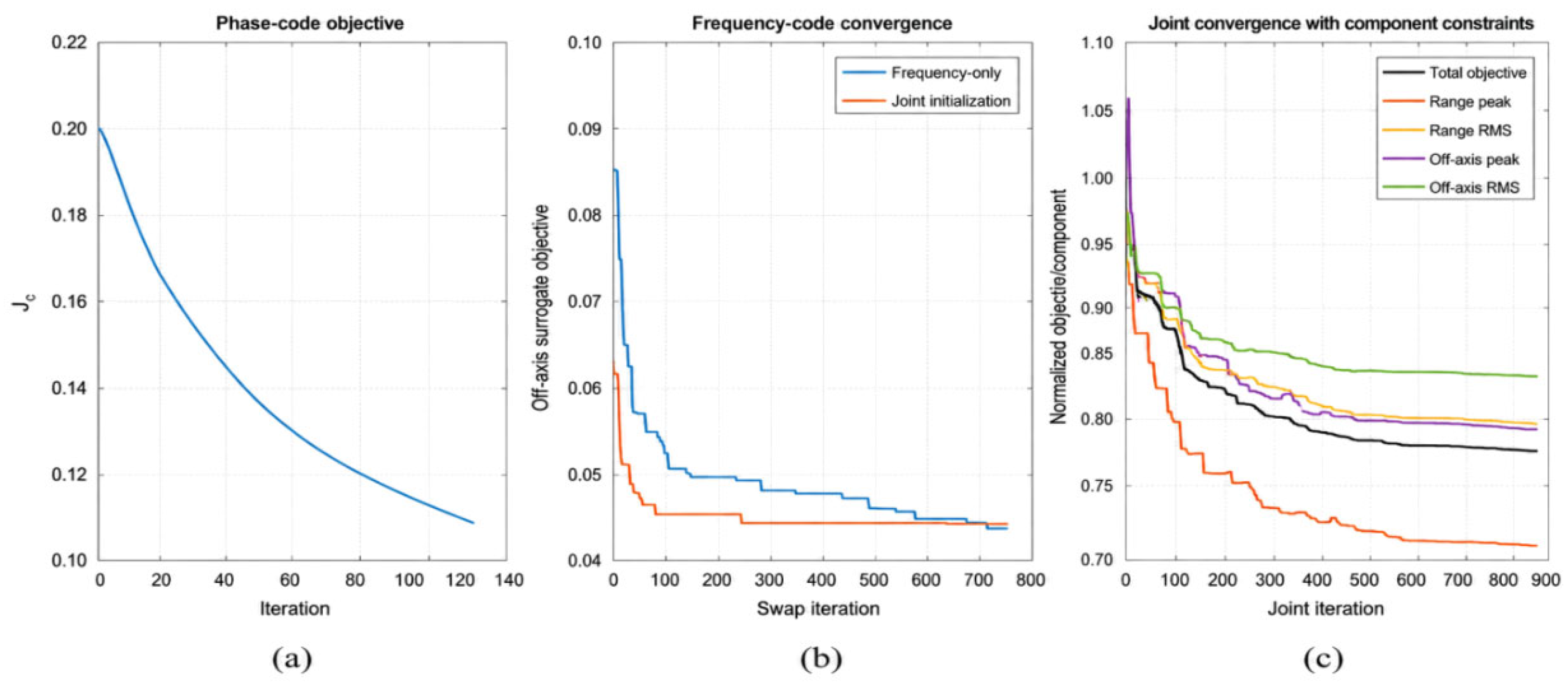
Figure 3.
Range–Doppler coupling slices, worst-case response envelopes, and range-sidelobe performance of different waveforms.
Figure 3.
Range–Doppler coupling slices, worst-case response envelopes, and range-sidelobe performance of different waveforms.
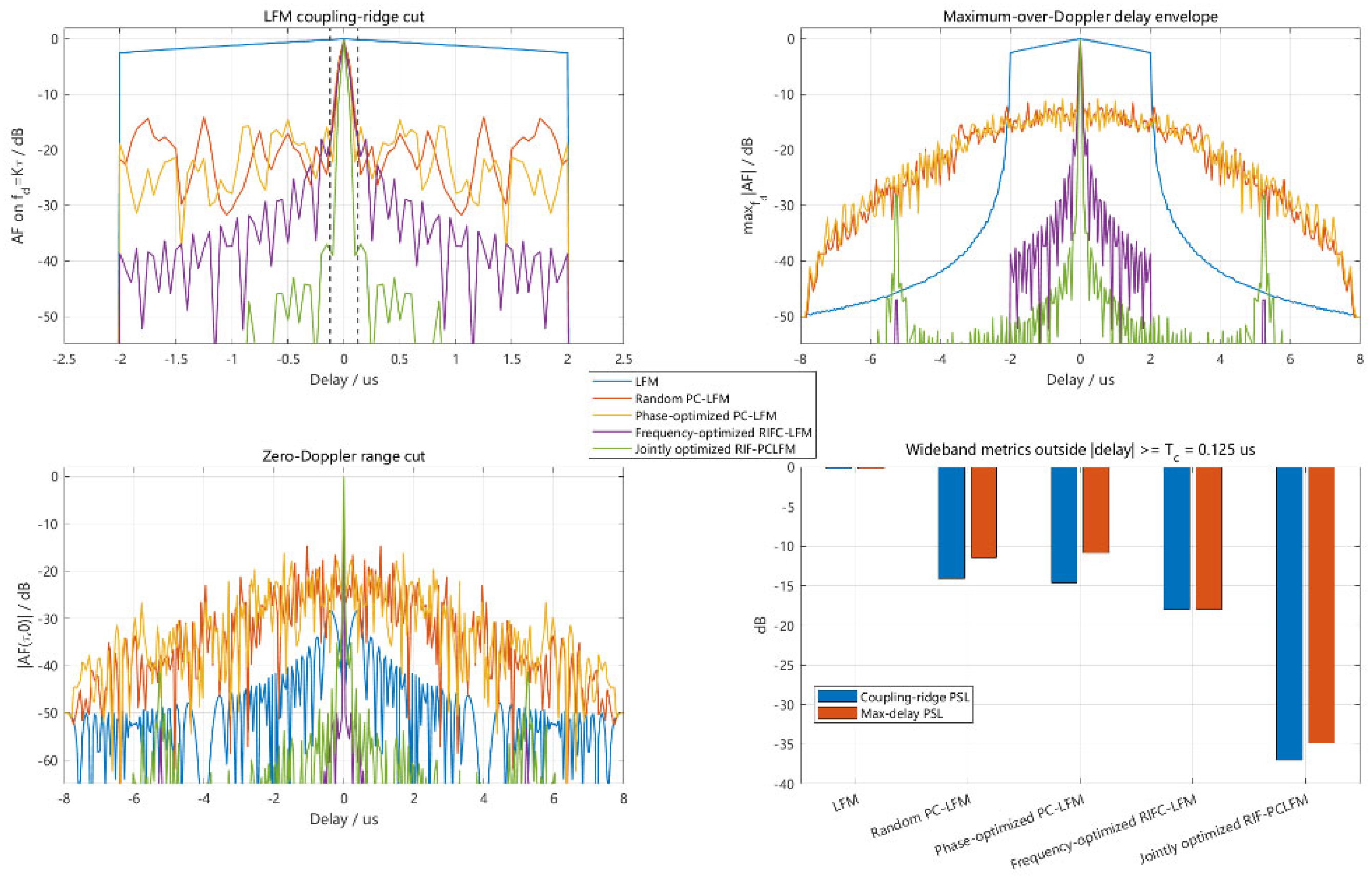
Figure 4.
Two-dimensional ambiguity functions of LFM, random PC-LFM, and jointly optimized RIF-PCLFM waveforms.
Figure 4.
Two-dimensional ambiguity functions of LFM, random PC-LFM, and jointly optimized RIF-PCLFM waveforms.
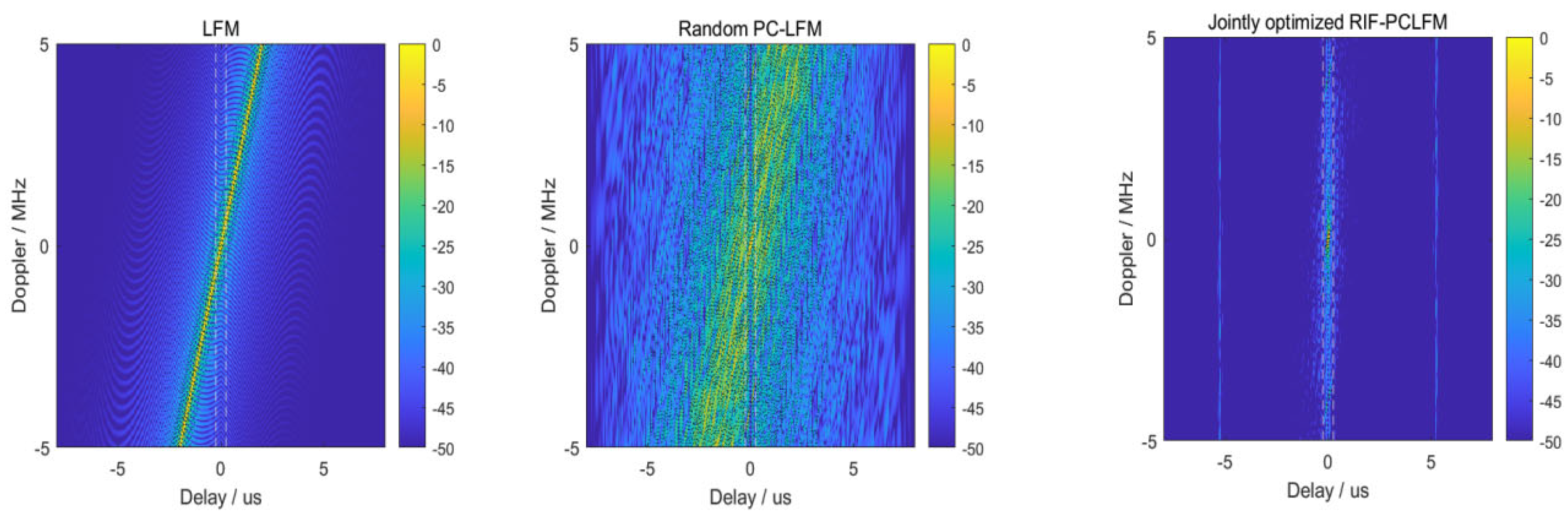
Figure 5.
Doppler focusing obtained by a uniform FFT and the exact NUDFT.
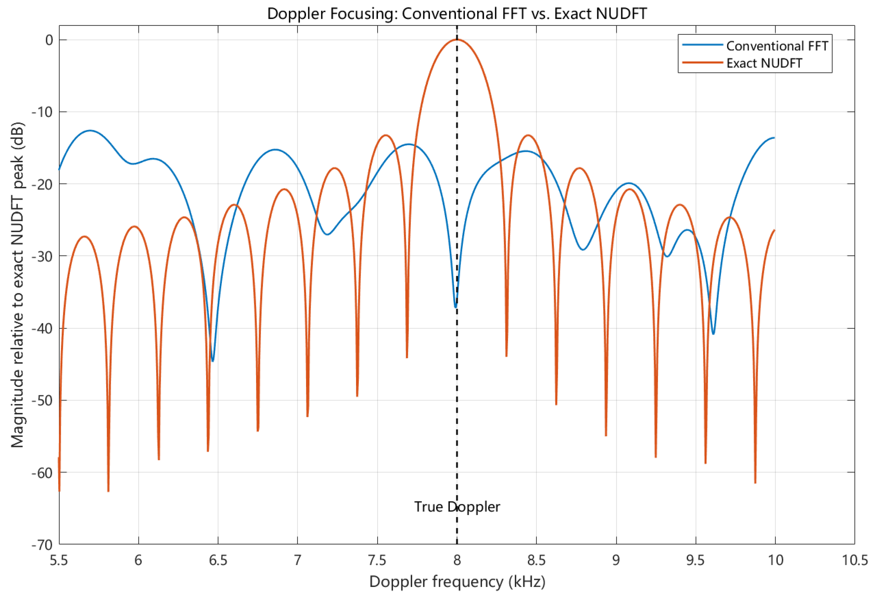
Figure 6.
Original RD spectra of LFM, random frequency-coded LFM, and RIF-PCLFM under three ISRJ types.
Figure 6.
Original RD spectra of LFM, random frequency-coded LFM, and RIF-PCLFM under three ISRJ types.
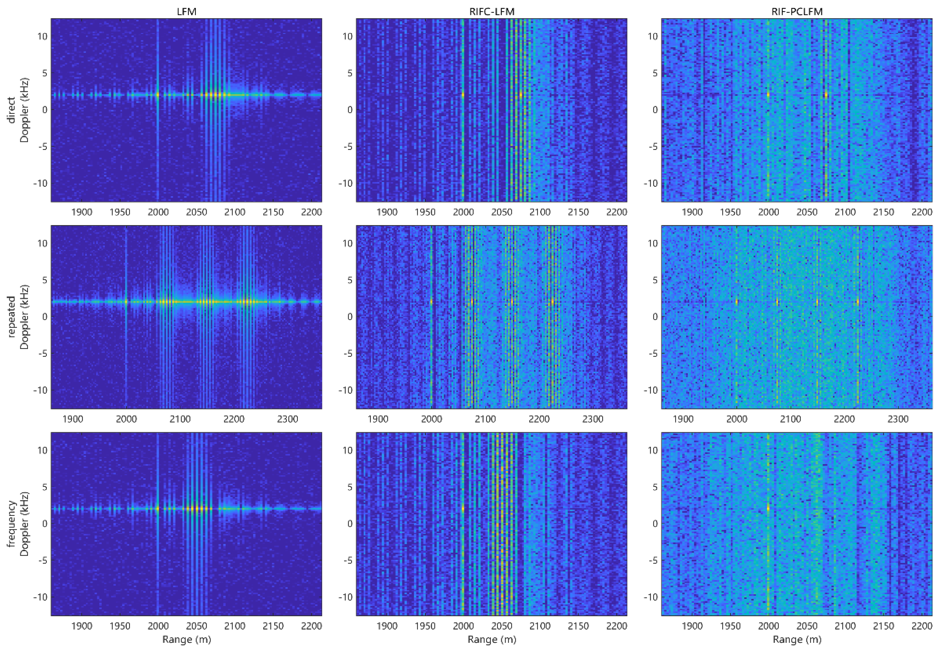
Figure 7.
False-target reconstruction, soft-mask construction, and RD-spectrum suppression for the three ISRJ types.
Figure 7.
False-target reconstruction, soft-mask construction, and RD-spectrum suppression for the three ISRJ types.
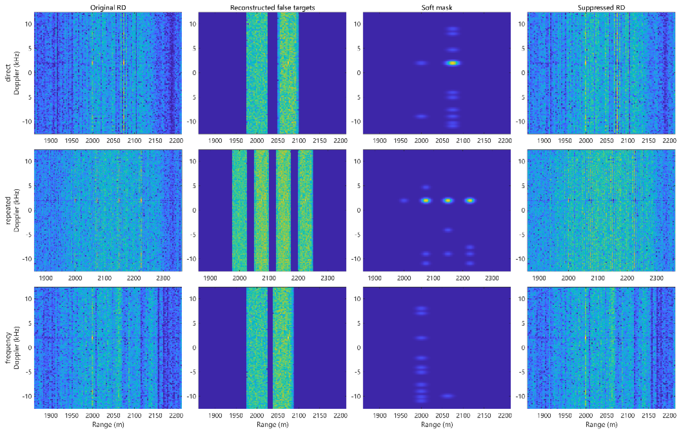
Figure 8.
Structural features of decoded range profiles for a genuine target and representative ISRJ candidates.
Figure 8.
Structural features of decoded range profiles for a genuine target and representative ISRJ candidates.
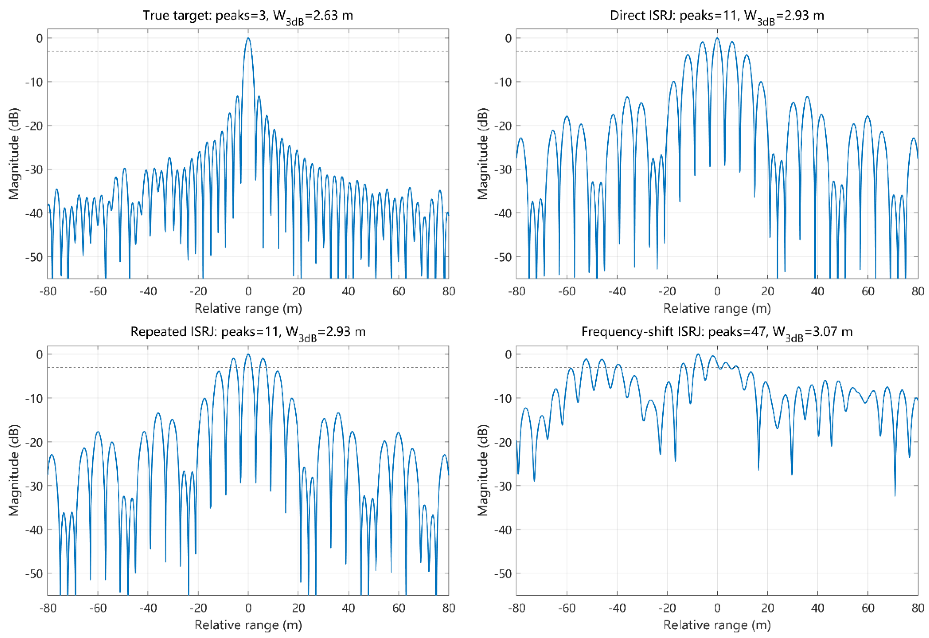
Figure 9.
. Enlarged views of RD-domain coarse estimation and target-protective soft suppression under ISRRJ: (a) original RD spectrum and detections; (b) reconstructed false-target spectrum; (c) coarse reconstruction scores; (d) suppression mask; (e) suppressed RD spectrum; (f) range cut at the target Doppler.
Figure 9.
. Enlarged views of RD-domain coarse estimation and target-protective soft suppression under ISRRJ: (a) original RD spectrum and detections; (b) reconstructed false-target spectrum; (c) coarse reconstruction scores; (d) suppression mask; (e) suppressed RD spectrum; (f) range cut at the target Doppler.
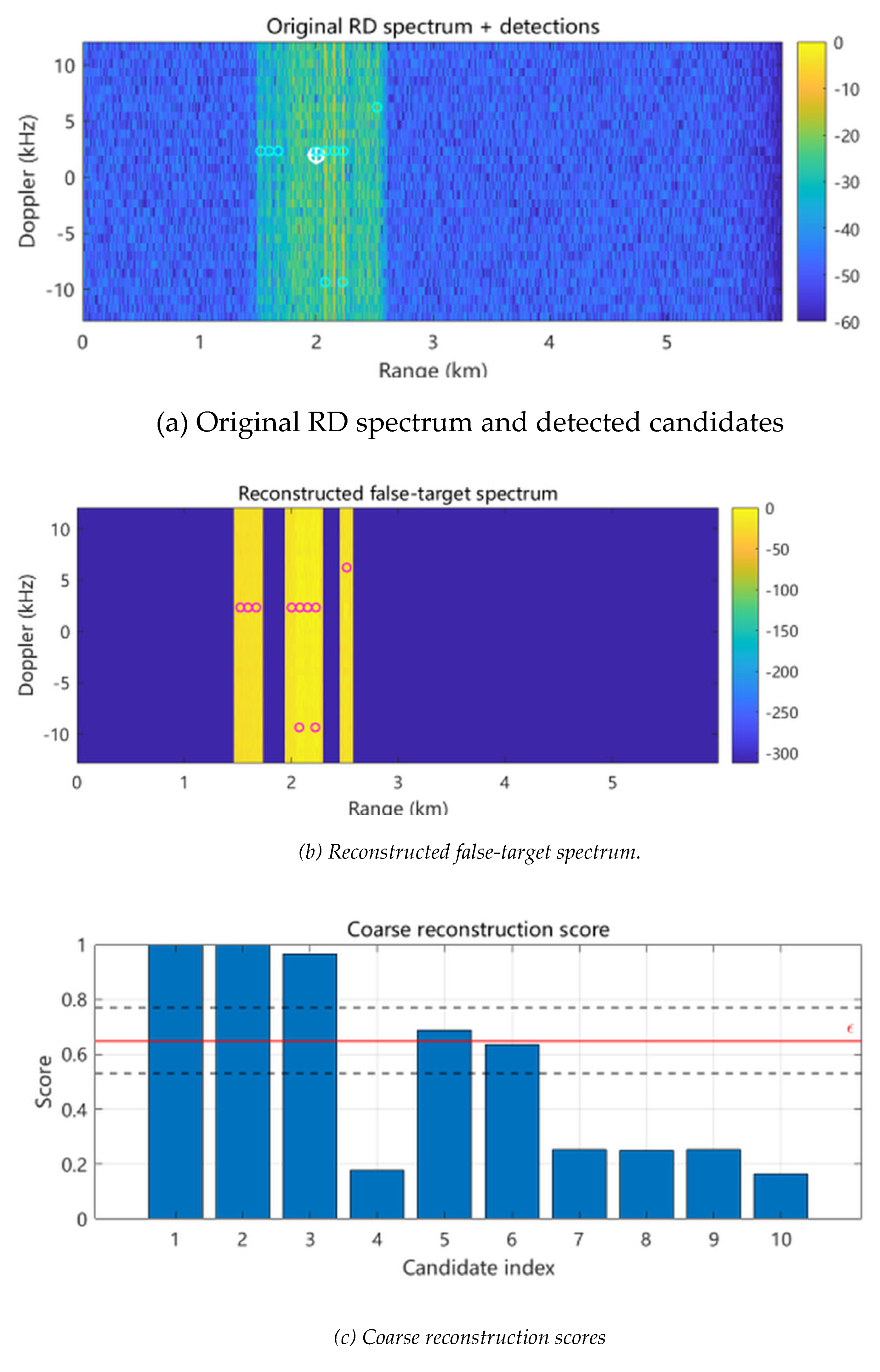
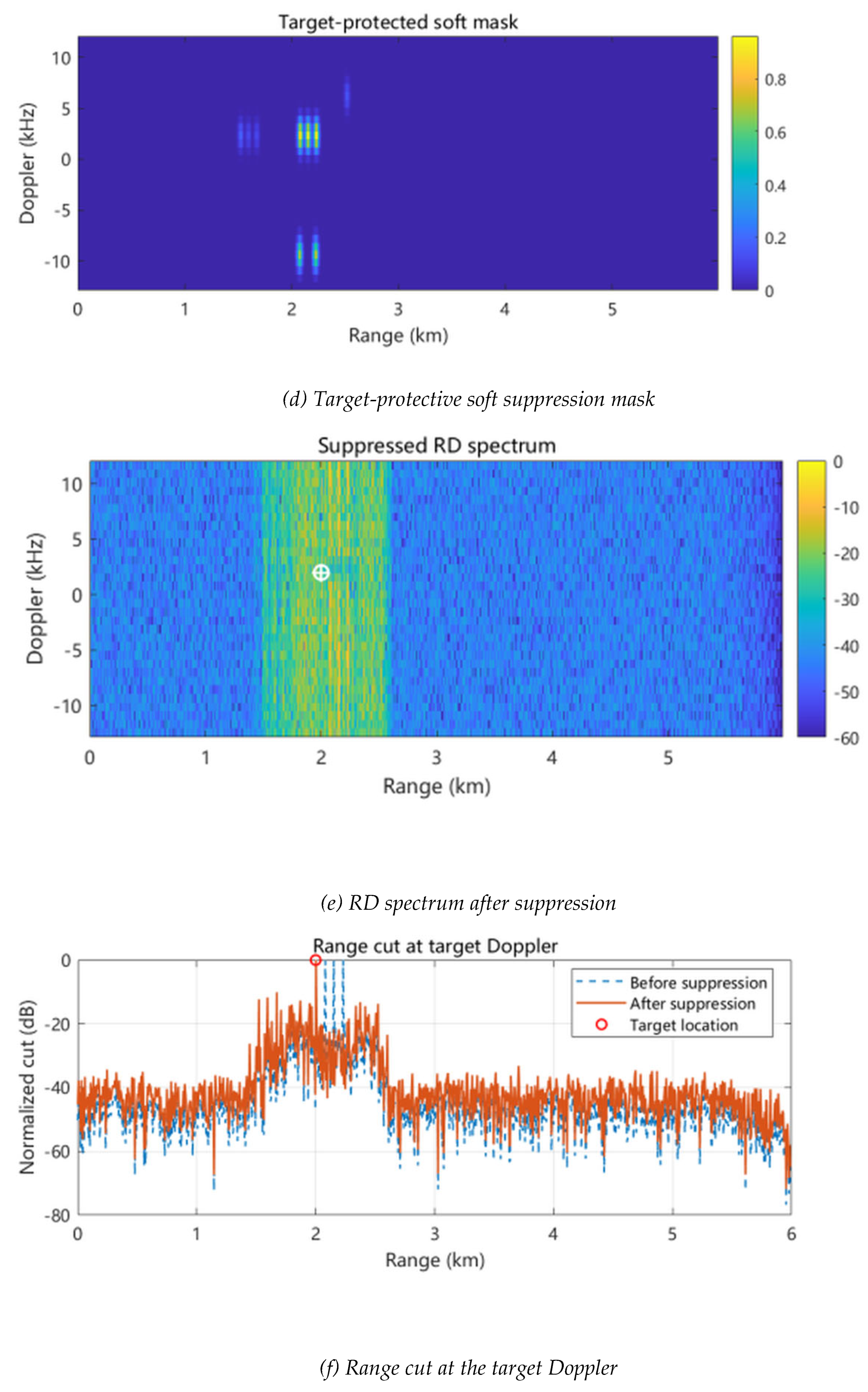
Figure 10.
Jamming-region recognition rate versus input SIR and SNR for ISDRJ, ISRRJ, and ISCRJ.
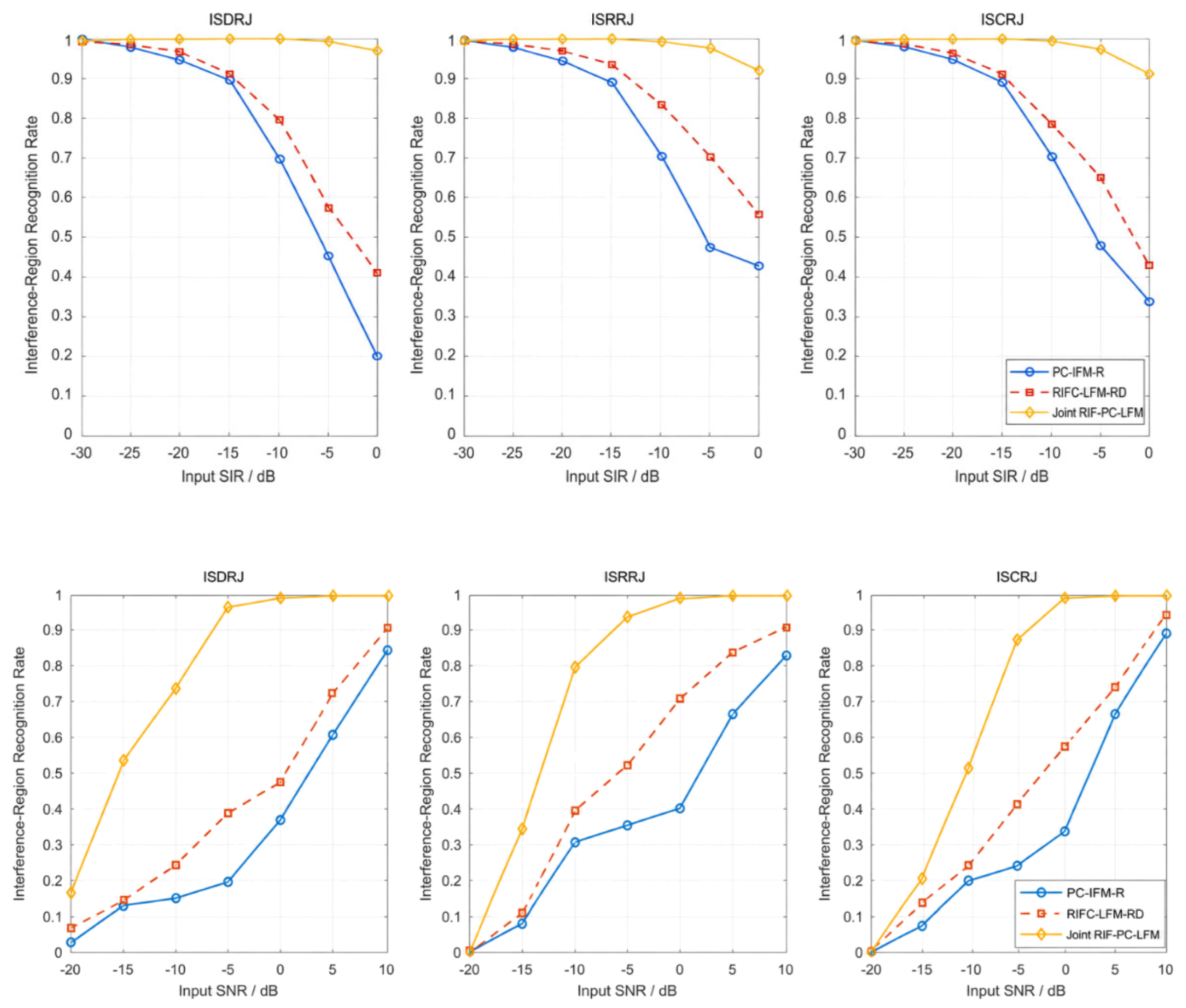
Figure 11.
Output SIR versus input SIR and SNR for ISDRJ, ISRRJ, and ISCRJ.
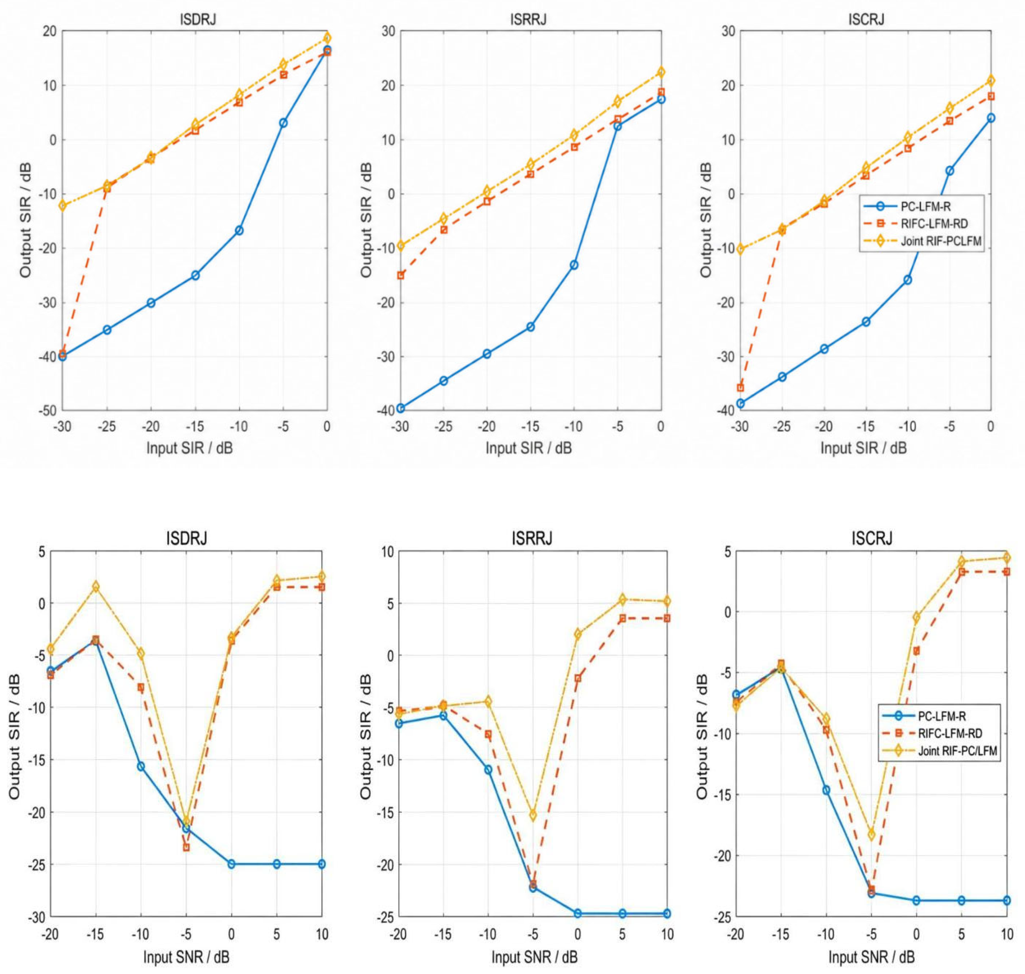
Table 1.
Radar, target, and ISRJ simulation parameters.
| Category | Parameter | Value | Unit |
|---|---|---|---|
| Radar | Carrier frequency | 1 × 10^9 | Hz |
| Radar | Signal bandwidth | 5 × 10^7 | Hz |
| Radar | Fast-time sampling rate | 5 × 10^7 | Hz |
| Radar | Pulse width | 4 | μs |
| Radar | Pulse repetition interval | 40 | μs |
| Radar | Pulse repetition frequency | 2.5 × 10^4 | Hz |
| Radar | LFM chirp slope | 1.25 × 10^13 | Hz/s |
| Radar | Range resolution | 3 | m |
| Radar | Pulses per CPI | 48 | — |
| Radar | CPI duration | 0.00192 | s |
| Radar | Fast-time record length | 1024 | — |
| Coding | Intra-pulse phase chips | 50 | — |
| Coding | Chip width | 0.08 | μs |
| Coding | Inter-pulse hopping span | 4 × 10^7 | Hz |
| Target | Target range | 2000 | m |
| Target | Target Doppler | 2000 | Hz |
| ISRJ | Sampling period | 2 | μs |
| ISRJ | Sampling width | 0.5 | μs |
| ISRJ | Sampling duty ratio | 0.25 | — |
| ISRJ | Forwarding delay | 0.5 | μs |
| ISRJ | ISRRJ repeat count | 3 | times |
| ISRJ | ISCRJ cyclic count | 3 | times |
Disclaimer/Publisher’s Note: The statements, opinions and data contained in all publications are solely those of the individual author(s) and contributor(s) and not of MDPI and/or the editor(s). MDPI and/or the editor(s) disclaim responsibility for any injury to people or property resulting from any ideas, methods, instructions or products referred to in the content. |
© 2026 by the authors. Licensee MDPI, Basel, Switzerland. This article is an open access article distributed under the terms and conditions of the Creative Commons Attribution (CC BY) license (http://creativecommons.org/licenses/by/4.0/).
Copyright: This open access article is published under a Creative Commons CC BY 4.0 license, which permit the free download, distribution, and reuse, provided that the author and preprint are cited in any reuse.