

Submitted:
12 November 2026
Posted:
16 November 2026
You are already at the latest version
Abstract
This study develops and evaluates a laboratory-scale Self-Learning Robotic System (SLRS) for an industrial motivated pick-and-place task using imitation learning and perception-guided manipulation. Human demonstrations are encoded using a Dynamic Movement Primitive (DMP)-based representation, while YOLOv8 object detection, stereo vision, point-cloud processing, and centroid estimation provide the three-dimensional target position. The perceived target and selected destination condition the demonstrated movement representation before Cartesian waypoint generation, inverse kinematics, MoveIt-based planning, trajectory refinement, and execution on a MyCobot 280 Jetson Nano manipulator. A separate image-classification component was evaluated before and after SMOTE balancing, producing a mean post-SMOTE training accuracy of 89.02% across three recorded runs; this value is interpreted as training performance rather than independent test performance. Robot execution was evaluated across four destination bins with 40 trials per trajectory condition. Mean completion time was 43.90 ± 3.61s without optimisation and 21.95 ± 1.80s with optimisation. The exact 2:1 relationship is reported as a characteristic of the recorded experimental dataset and requires independent verification using controller-based timing. The methodological contribution is the perception-conditioned transfer of demonstration-derived movement information into robot-specific manipulation through a DMP-based process that combines perception, planning, and robot execution.
Keywords:
imitation learning
; self-learning robotic system
; industrial robotics
; robotic manipulation
; human demonstration
; stereo vision
; trajectory optimisation
; pick-and-place
1. Introduction
Industrial robots perform repetitive operations with consistency, but changes in task sequence, object position, or production requirements can require substantial reprogramming [1,2,3]. Imitation Learning (IL), also known as Learning from Demonstration (LfD) or Programming by Demonstration, provides a practical way to transfer human task knowledge to a robot from observed examples [4,5,6,7,8]. A demonstration may contain actions, trajectories, state transitions, or task goals from which an executable policy can be learned. Behavioural Cloning (BC) uses supervised learning to map observed states to demonstrated actions, while approaches such as Dataset Aggregation and Inverse Reinforcement Learning address problems including distributional shift, limited demonstration coverage, and operation in previously unseen states [5,6,9].
For industrial manipulation, learning a state–action relationship is only one part of the task. Human and robot kinematics differ, as do workspace limits, joint ranges, velocity limits, and grasping capability. The robot must also identify the relevant object, estimate its position, generate a feasible path, satisfy kinematic constraints, and execute the motion reliably. Errors in perception or localisation can affect the trajectory and, in turn, the manipulation outcome. These issues are particularly relevant to warehouse and manufacturing tasks such as sorting, kitting, material transfer, and pick-and-place, where object and destination positions may change. Human operators can respond naturally to such changes, whereas a conventionally programmed robot may require new coordinates, waypoints, or control sequences. Demonstration-based learning provides another route by combining task information learned from human examples with perception-guided planning to produce robot-compatible actions [1,3,10,11,12,13].
This study builds on earlier Self-Learning Robotic System (SLRS) research. The first industrial SLRS study introduced a smart-factory platform based on machine and deep imitation learning [14], while subsequent work developed the computer-aided modelling and simulation framework, including waypoint-based trajectory generation and robot task reproduction [15]. The present study extends this development to physical robot hardware using a MyCobot 280 Jetson Nano manipulator equipped with stereo vision and deep-learning-based object detection. Stereo images are processed to estimate depth and construct three-dimensional point-cloud data, and clustering is used to estimate the target-object position before the resulting coordinates are transferred to the planning module. The six-axis manipulator uses an interchangeable gripper, has a nominal payload of up to 250 g, and provides an approximate reach of 280 mm.
Human demonstrations provide the task information required for robot execution. Rather than directly reproducing human joint motion, the SLRS converts demonstrated behaviour into movement representations and task waypoints suited to the robot. Dynamic Movement Primitives (DMPs) provide reusable movement representations, while waypoint generation, inverse kinematics, and motion planning convert the adapted movement information into feasible robot trajectories. This allows the demonstrated task structure to be retained while the geometric and control stages account for robot-specific constraints [16,17,18]. SMOTE [19] was also applied to the image-classification data to improve minority-class representation, with classification performance reported separately from robot-execution measures so that learning results and manipulation performance are not conflated. Robot testing covered four destination bins, with ten trials conducted for each bin under both non-optimised and optimised trajectory configurations.
The methodological contribution of this study is a perception-conditioned demonstration-transfer method within the SLRS. Demonstration-derived movement information is retained using a reusable DMP representation, while the perceived three-dimensional target position and selected destination provide task-specific spatial conditions for waypoint generation. Inverse kinematics, MoveIt-based motion planning, trajectory refinement, and robot execution then convert the adapted representation into physical manipulation. The method is evaluated through repeated laboratory-scale pick-and-place trials across four destination positions. The remainder of the paper reviews the relevant literature and research gap, describes the SLRS and experimental procedure, presents the learning and robot results, discusses their implications, and outlines the next stages of evaluation.
1.1. Imitation Learning for Robotic Manipulation
Imitation learning includes several learning formulations. Behavioural Cloning treats expert demonstrations as supervised examples and teaches a direct mapping from observations to actions [5,6]. Its main weakness is compounding error: a small execution deviation can move the robot into states that were poorly represented in the demonstrations. Dataset Aggregation addresses this by adding expert supervision for states visited by the learner [9]. Inverse Reinforcement Learning instead infers an underlying objective or reward from expert behaviour [6]. For embodied robots, demonstration-driven learning is also attractive because data collection and unsafe exploration can be costly [20].
Recent LfD research has moved beyond simple trajectory mimicking towards reusable representations, adaptation to new conditions, interactive correction, and transfer across different embodiments [10,11]. These issues are important because the human demonstrator and the robot have different kinematic structures and motion capabilities. An intermediate representation is therefore needed before demonstrated human motion can be transferred safely and effectively to an articulated manipulator.
Task-space trajectories, waypoints, movement primitives, and learned task representations can provide this intermediate layer. They retain the parts of a demonstration that matter to the task while leaving inverse kinematics and robot-specific planning to determine the final motion. This is particularly useful when the relationship between the object and its destination matters more than direct reproduction of the demonstrator's joint motion. Programming-by-demonstration studies and manipulation surveys make the same distinction between task representation and embodiment-specific execution [21,22].
Earlier SLRS studies followed this principle. The initial platform introduced machine and deep imitation learning for industrial robotics [14], while subsequent computer-aided work developed waypoint-based movement and simulated execution [15]. Recent manufacturing research also shows continued interest in one-shot demonstration and imitation-based optimisation for industrial tasks [23,24]. Chen et al. [25] further developed vision-based learning from multiple contact-free human demonstrations using an adaptive DMP formulation for pick-and-place execution under changing conditions. This recent work highlights the continuing importance of movement representation, visual perception, and trajectory adaptation in transferring demonstrated behaviour to physical robotic manipulators.
1.2. Perception-Guided Manipulation
Imitation-based manipulation requires the learned task to be matched to the current scene. Reliable execution therefore depends on identifying and localising the target object before generating robot motion. Deep visual models can extract task-relevant information from images, while modular robotic architectures allow perception, localisation, planning, and control to be evaluated independently [26].
The SLRS follows this modular structure. YOLOv8 identifies the target object, stereo vision estimates depth, and the resulting data are converted into a three-dimensional point cloud. Clustering then estimates the target centroid, which is transferred to the motion-planning stage.
Stereo vision was retained because the experimental platform used a calibrated dual-RGB-camera arrangement that supported both visual detection and depth estimation from the same image pair [27]. This choice does not imply superiority over RGB-D sensing. Passive stereo remains sensitive to image texture, illumination, and correspondence quality, whereas RGB-D sensors can provide more direct depth measurements at short range. The controlled workspace and textured objects used in this study were suitable for the stereo configuration; direct comparison with RGB-D sensing remains a useful direction for future evaluation.
Successful manipulation depends on more than object detection alone. Accurate localisation, grasp-point selection, feasible motion planning, and stable execution are also required. Recent studies have addressed visual grasp-point selection [28], tactile perception for adaptive grasping [29], and deep-learning-based grasp detection for robotic bin picking [30]. These studies support the treatment of perception, localisation, grasping, and robot execution as connected stages of an industrial manipulation system.
1.3. Motion Representation, Planning, and Control
Imitation-learning output must ultimately be converted into robot motion that satisfies kinematic and dynamic constraints. This distinguishes robotic IL from learning problems in which prediction accuracy is the final outcome.
Movement primitives and waypoint representations form the link between demonstrated behaviour and conventional robot control. Dynamic Movement Primitives can encode reusable motions while allowing the goal or timing to change [16,17,18]. In the SLRS, demonstrated movement information is retained and translated into waypoints and robot-compatible trajectories. A recent comparative study by Jahn et al. [31] evaluated DMPs alongside other movement-encoding frameworks using 7,652 human manipulation trajectories. Their results showed that DMPs provide efficient movement encoding and performed well when the start and end conditions changed, supporting their continued use as a reusable representation for demonstration-derived robotic motion.
Inverse kinematics maps Cartesian targets to robot joint configurations, while motion planning finds a feasible path through configuration space. The implementation uses MoveIt for planning and execution. RRT-based planning explores the high-dimensional configuration space to identify feasible manipulation paths. MoveIt and its industrial extensions are described in [32,33], while RRT-based planners are well established for this class of search problem [34,35].
The SLRS combines learned task behaviour with conventional planning and control. These stages enforce workspace, joint, actuator, collision, and end-effector constraints so that the learned behaviour remains compatible with the manipulator's mechanical limits.
1.4. Data Imbalance and Evaluation Beyond the Training Data
Learning accuracy depends on both the amount of data and how the classes are represented. If some objects, actions, or operating conditions appear much more often than others, a high aggregate accuracy can hide weaker performance in minority classes. SMOTE addresses this imbalance by generating synthetic minority-class samples between neighbouring observations [19]. This is relevant to robotic learning because an infrequent class may still represent an important object, action, or operating state. Learning results are examined before and after class balancing. SMOTE is used to strengthen minority-class representation, and the post-SMOTE values are reported separately from the original aggregate accuracy. A more balanced dataset gives a clearer view of class representation, but reliable operation under new object positions, lighting, workspace layouts, and task states also depends on the breadth of the demonstrations and the degree of distributional shift. These remain central challenges in imitation learning [4,5,6,7,8,9,10].
1.5. Research Gap and Study Positioning
Previous studies have advanced imitation learning, robotic perception, motion planning, and learned manipulation, but several gaps remain relevant to the industrial SLRS considered here. Many studies report learning or prediction results separately from the full manipulation chain, whereas industrial task execution requires perception, localisation, learning, waypoint generation, inverse kinematics, planning, and robot control to operate together. Earlier SLRS studies established the system concept and computer-aided modelling framework [14,15], while a separate healthcare study examined assistive manipulation and human–robot interaction [36]. Repeated physical robot testing was therefore required to assess perception, demonstration-derived behaviour, planning, and execution together in a warehouse-based manipulation task.
The methodological gap addressed in this study concerns the transfer of demonstrated task behaviour into perception-conditioned robot execution. The proposed SLRS retains demonstration-derived movement structure through a DMP-based representation, while the perceived three-dimensional target position and selected destination provide the spatial conditions required for task-specific waypoint generation. These waypoints are then processed through inverse kinematics, MoveIt-based motion planning, trajectory refinement, and physical robot execution. Learning accuracy and robot task performance are evaluated separately because they describe different stages of this process.
This approach extends the earlier conceptual and computer-aided SLRS studies [14,15] by implementing and evaluating the complete demonstration-to-execution process on physical robot hardware under controlled laboratory conditions. The study therefore addresses the following research question: To what extent can a perception-guided Self-Learning Robotic System using imitation learning reproduce demonstrated manipulation behaviour for an industrially motivated task, and how does trajectory optimisation affect repeated sorting and pick-and-place execution under controlled laboratory conditions?
2. Materials and Methods
2.1. Experimental SLRS Architecture
The SLRS transfers a human-demonstrated manipulation task to the robot through perception, localisation, task representation, planning, trajectory refinement, and feedback-based execution. The workflow begins with a human demonstration, while RGB and stereo observations are used to identify the target object and estimate its three-dimensional position. The demonstrated behaviour is converted into a robot-compatible representation, task-specific waypoints are generated, and a feasible trajectory is planned and refined before execution. Task learning and low-level execution are handled as separate stages: the demonstration defines the required task structure, perception describes the current workspace, and the planning and control modules convert both inputs into executable robot motion. Figure 1 summarises this information flow.
The architecture uses two distinct feedback paths. Before motion generation, the perception subsystem estimates the target-object position from RGB and stereo observations. YOLOv8 identifies the target region, stereo processing estimates depth, and point-cloud clustering provides the three-dimensional object centroid used for waypoint generation; invalid and outlying depth measurements are removed before the centroid is passed to the motion-planning stage. During physical execution, measured joint positions are compared with the desired trajectory, and the resulting tracking error is used by the trajectory-alignment and control stage to maintain the commanded motion within the configured joint and workspace constraints. The present implementation does not use continuous visual servoing in which the object position is repeatedly reestimated and the full trajectory is replanned at every control cycle. Visual localisation is therefore used primarily to establish the manipulation target before trajectory generation, while joint-state feedback provides closed-loop correction during robot execution.
2.2. Robotic Platform
Experiments used a MyCobot 280 Jetson Nano manipulator. The platform combines a six-axis articulated arm, an NVIDIA Jetson Nano computing unit, and an interchangeable robotic gripper. Its nominal payload is 250 g and its approximate reach is 280 mm.
Table 1 summarises the main hardware and sensing configuration used in the experiments.
Figure 2 shows the MyCobot 280, the warehouse-based manipulation workspace, and the main configuration used during task execution.
All timing measurements reported in this paper were recorded with the six-axis MyCobot 280. The earlier simulation study [15] used a simplified robot model.
2.3. Human Demonstration and Task Representation
Human operators demonstrated the required object-transfer behaviour while the system recorded visual information from the manipulation sequence. A demonstration dataset can be represented as shown in Equation (1),
(1)
where st represents an observed state and at represents the corresponding demonstrated action. Because human and robot kinematics differ, the observed behaviour is not transferred as direct joint motion. Instead, the demonstration is converted into robot-compatible movement information that preserves the task structure while allowing later stages to account for the robot configuration and workspace.
Dynamic Movement Primitives are used in the SLRS as the intermediate representation between human demonstration and robot-specific motion generation [16,17,18]. Demonstration-derived movement information is encoded into a reusable DMP representation and stored within the movement library. During execution, the stored representation provides the movement structure associated with the demonstrated behaviour, while the perceived object position and selected destination define the task-specific spatial conditions. The adapted movement information is then converted into Cartesian waypoints, after which inverse kinematics and MoveIt-based planning generate the executable robot trajectory. In this way, the DMP layer connects demonstration processing with localisation, waypoint generation, planning, and physical manipulation without requiring direct replication of the demonstrator’s joint motion.
| Algorithm 1. Integrated SLRS learning and execution procedure. |
| Input: human demonstration D, stereo/RGB observations, trained object detector, robot configuration |
| Output: executed pick-and-place task |
| 1. Acquire the human demonstration and extract task-relevant object and motion information. |
| 2. Acquire RGB and stereo observations of the workspace. |
| 3. Detect the target object using YOLOv8 and determine its image-space bounding box. |
| 4. Estimate stereo disparity and depth and construct the three-dimensional point cloud. |
| 5. Filter invalid and outlying three-dimensional measurements, estimate the target-object centroid, and transfer the resulting target position to the task representation. |
| 6. Encode the demonstration-derived movement information using the DMP-based movement representation. |
| 7. Store or retrieve the corresponding DMP representation from the movement library for the demonstrated task. |
| 8. Adapt the stored movement representation to the detected target position and selected destination and generate task-specific cartesian waypoints. |
| 9. Solve inverse kinematics for each waypoint and generate a feasible motion plan using MoveIt and the configured sampling-based planner. |
| 10. Apply trajectory alignment and the configured optimisation stage. 11. Execute grasp, transfer, and placement using the MyCobot 280 while monitoring measured joint positions. Compare the measured robot state with the desired trajectory and use the resulting tracking error for feedback-based trajectory alignment until task completion. |
2.4. Object Detection and Three-Dimensional Localisation
The perception subsystem combines YOLOv8 object detection with stereo-based three-dimensional localisation. YOLOv8 provides the target class and image-space bounding box used by the subsequent localisation stages [37,38], while stereo vision provides the depth information required for manipulation. The detector used the YOLOv8n architecture and a custom dataset of 1,216 annotated images of retail and convenience-store objects used in the laboratory tasks. Images were labelled with bounding boxes and augmented using rotation, flipping, scaling, and noise. The dataset comprised 851 training images (70%), 243 validation images (20%), and 122 test images (10%), and the recorded training run covered 300 epochs. The archived detector-training record includes precision, recall, mAP50, and mAP50–95 learning curves. Toward the end of training, precision stabilised at approximately 0.6 and recall approached 0.4, while both mAP50 and mAP50–95 increased progressively. These values are reported as training and validation indicators for the recorded detector run and are interpreted separately from independent held-out test-set performance. For a calibrated stereo pair, object depth is related to disparity by Equation (2).
(2)
where Z is the estimated depth, f is the focal length, B is the stereo-camera baseline, and d is the disparity between corresponding image locations. Stereo processing converts the aligned image pair into disparity, depth, and three-dimensional point-cloud data. After detection, the points within the object region are extracted and filtered to reduce invalid and outlying measurements. K-means clustering [39] is then applied to estimate a representative spatial centre using the objective in Equation (3).
(3)
where Ci represents cluster i, xj is a point assigned to the cluster, and μi is its centroid. The selected target-object centroid is subsequently passed to the motion-planning stage as the three-dimensional manipulation target.
The stereo-processing pipeline uses calibrated left and right views, image rectification, correspondence estimation, disparity-derived depth, and point-cloud reconstruction. Intrinsic and extrinsic camera parameters are applied at run time. The available experimental record supports the localisation workflow described here, although complete numerical calibration logs, fixed stereo-matching settings, run-level K-means parameters, and quantitative localisation-error measurements were not retained for the reported experiment. These parameters should be recorded in future replication studies. Figure 3 summarises the complete perception sequence from RGB/stereo acquisition and YOLOv8 detection to depth estimation, point-cloud processing, clustering, and transfer of the estimated centroid to the manipulation planner.
| Algorithm 2. Stereo-based 3D object localisation using YOLOv8 and K-means |
| Input: left image IL, right image IR, calibrated stereo parameters |
| Output: target centroid C = (Xc,Yc,Zc) |
| 1. Capture and rectify the stereo image pair. |
| 2. Detect the target object and bounding box using YOLOv8. |
| 3. Determine stereo correspondences and compute disparity d. |
| 4. Estimate depth using Equation (2), . 5. Convert the depth information into a three-dimensional point cloud. |
| 6. Crop the point cloud to the detected object region. |
| 7. Remove invalid measurements and outliers from the object-region point cloud. |
| 8. Apply K-means clustering to the remaining three-dimensional points. |
| 9. Select the target-object cluster and calculate its centroid C. |
| 10. Transfer C to the robot motion-planning module as the manipulation target. |
2.5. Waypoint Generation and Motion Planning
The manipulation sequence is represented by Cartesian waypoints corresponding to the main task stages: approach, grasp, transfer, and placement, as expressed in Equation (4). For each waypoint, inverse kinematics determines the corresponding robot joint configuration using standard manipulator kinematics [40], as shown in Equation (5)
W = {w1,w2,…,wn} (4)
qi = IK(wi) (5)
where qi denotes the robot configuration associated with waypoint wi. This representation preserves the demonstrated task structure while allowing the robot to determine its own feasible joint configurations. Earlier SLRS simulation work used trapezoidal velocity profiles and polynomial interpolation for this purpose [15].
ROS and MoveIt are used to generate the executable motion between waypoint configurations while accounting for kinematic and workspace constraints. RRT-based planning searches the robot configuration space for a feasible path, with established MoveIt and sampling-based planning methods providing the basis for this stage [32,33,34,35]. Before execution, the planned path is checked against the configured joint and workspace constraints. Once the perceived target position and destination are available, the demonstration-derived task representation is converted into Cartesian waypoints, inverse kinematics determines the corresponding joint configurations, and MoveIt generates the executable path. Figure 4 summarises this sequence from task representation and target localisation through waypoint generation, joint-space planning, trajectory refinement, and robot execution.
| Algorithm 3. Demonstration-derived waypoint generation and robot motion planning |
| Input: demonstrated task representation, target centroid C, destination bin |
| Output: executable robot trajectory Q |
| 1. Retrieve the demonstrated manipulation behaviour and target destination. |
| 2. Determine the object pick position from the estimated centroid C. |
| 3. Define approach, grasp, lift/transfer, placement, and retreat waypoints. |
| 4. Solve inverse kinematics for each Cartesian waypoint. |
| 5. Reject configurations that violate joint or workspace constraints. |
| 6. Supply feasible waypoint configurations to MoveIt. |
| 7. Generate a collision-feasible path using the configured sampling-based planner. |
| 8. Interpolate the trajectory between successive configurations. |
| 9. Send the planned trajectory to the robot controller for execution. |
2.6. Trajectory Alignment and Optimisation
Trajectory alignment is used to refine the demonstrated manipulation sequence while maintaining the position, velocity, and acceleration constraints applied at key points along the planned motion. A fifth-order polynomial trajectory is expressed by Equation (6), with its coefficients determined from the corresponding boundary conditions. For feedback-based execution, trajectory error is defined by Equation (7),
q(t) = a0 + a1t + a2t2 + a3t3 + a4t4 + a5t5 (6)
e(t) = qd(t) − q(t) (7)
where qd(t) denotes the desired trajectory and q(t) represents the measured trajectory. The implementation combines quintic polynomial planning with feedback-based alignment between desired and measured motion, following standard closed-loop control principles [41].
In the present implementation, the feedback term represents robot-state correction rather than continuous image-based visual servoing. The three-dimensional target position is first estimated by the perception subsystem using object detection, stereo depth, point-cloud processing, and centroid estimation. This target is then passed to the motion-planning stage and used to generate Cartesian waypoints and the corresponding robot trajectory. During execution, measured joint positions are compared with the desired trajectory, and the resulting tracking error is used by the trajectory-alignment and control stage to maintain the commanded motion within the configured joint and workspace constraints. If the estimated object position is found to be unsuitable before execution, the perception and planning sequence must be repeated using an updated target estimate before a new trajectory is generated. The current system does not perform continuous visual re-localisation or complete trajectory replanning at every control cycle; the closed-loop architecture therefore combines perception-based target estimation before motion generation with joint-state feedback during robot execution. Stochastic Gradient Descent (SGD) is used in model training, while Sequential Quadratic Programming (SQP) is used for constrained optimisation within the SLRS. These methods address different optimisation problems. The SGD update is given by Equation (8),
θk+1 = θk − η∇θk (8)
(9)
where η denotes the learning rate, and Lk denotes the current loss, while the SQP formulation follows standard constrained numerical optimisation principles [42] and is represented by Equation (9). In this formulation, the constraints represent mechanical or operational limits imposed on the trajectory or control variables.
For the recorded timing experiment, analysis is based on the two implemented trajectory configurations: non-optimised and optimised. The timing results are therefore interpreted at the configuration level rather than as a solver-specific assessment of SQP. A detailed SQP evaluation would require the objective function, decision variables, solver settings, and run-level optimisation records to be retained for each experiment.
| Algorithm 4. Trajectory alignment and optimised pick-and-place execution |
| Input: reference waypoints W, current robot state q |
| Output: optimised executable trajectory |
| 1. Generate the reference trajectory from the demonstration-derived waypoints. |
| 2. Apply smooth polynomial interpolation between key waypoints. |
| 3. Apply initial and final position, velocity, and acceleration constraints. |
| 4. Read the current robot state and evaluate the reference tracking error e(t) = qd(t) − q(t). |
| 5. Refine trajectory/control parameters while retaining robot and operational constraints. |
| 6. Validate the updated trajectory against workspace and joint constraints. |
| 7. Execute the trajectory through the robot controller. |
| 8. Monitor feedback throughout execution and record task-completion time. |
2.7. Dataset Balancing and Classification-Accuracy Evaluation
The classification results are derived from the MATLAB image-classification component used during SLRS modelling. Images were organised into Red, Green, and Blue object classes, and a pre-trained ResNet-50 network was used for feature extraction followed by classifier training on the extracted features and labels. The MATLAB workflow used separate training and testing datasets, with evaluation based on confusion matrices. However, the archived experimental record does not retain the run-specific independent test metrics associated with the three pre- and post-SMOTE accuracy values reported in this study. The available values are therefore treated solely as indicators of training performance and are not used to infer classifier effectiveness on previously unseen data. Robot task results are reported separately as the end-to-end manipulation evaluation.
Because the image-classification data were imbalanced, SMOTE [19] was used to increase minority-class representation before post-balancing training performance was evaluated. For an observation xi and one of its neighbouring minority observations xnn, a synthetic observation generated as shown in Equation (10)
xnew = xi + λ(xnn − xi), 0 ≤ λ ≤ 1 (10)
(11)
The mean post-SMOTE training accuracy across the three recorded runs was calculated using Equation (11). with the pre- and post-SMOTE results presented side by side in Section 3.1. SMOTE improves class representation through nearest-neighbour interpolation, but a complete evaluation requires the method to be applied only to the training partition and assessed on an untouched test set using accuracy, precision, recall, F1-score, and a confusion matrix.
2.8. Warehouse-Based Pick-and-Place Experimental Protocol
The robot was evaluated in a warehouse-based object-sorting and pick-and-place task. A human operator first demonstrated the required transfer, after which the SLRS detected and localised the target, generated robot-compatible motion, and executed the pick-and-place sequence. Four destination positions, labelled Bin A to Bin D, were tested. Each destination was repeated ten times under each trajectory condition, giving 40 trials per condition.
Two trajectory conditions were compared: the non-optimised manipulation sequence and the corresponding optimised configuration. Total task-completion time was the main quantitative outcome and was measured manually using a stopwatch from the start of robot execution to completion of object placement. For each trial, the elapsed time was recorded directly from the physical robot experiment and entered into the experimental record for the corresponding destination and trajectory condition. The values reported in Table 3 are the individual trial-level timing records used to calculate the descriptive statistics in Table 4 and Table 5. The optimised values were not generated by applying a fixed 50% reduction during statistical analysis; the 2:1 relationship was identified when the recorded trial values were compared after data collection. The same timing procedure was applied to both trajectory configurations.
2.9. Data Analysis
For each destination, mean completion time was calculated using Equation (12), while the proportional reduction produced by optimisation was calculated using Equation (13). Task-completion time serves as the primary robot-level quantitative measure in the present study because it was recorded consistently across all experimental trials. The broader validation framework includes detector precision and recall, three-dimensional localisation error, Cartesian positioning accuracy, trajectory-tracking RMSE, grasp-success rate, and recovery performance. These measures should be recorded for each trial in the next stage of SLRS validation.
(12)
(13)
2.10. Scope of Validation
Experiments were performed indoors under controlled conditions as a laboratory-scale proof of concept. The reported results therefore characterise the tested robot, workspace, objects, destination bins, sensing conditions, and trajectory configurations used in this study. The experimental comparison focuses on the non-optimised and optimised trajectory configurations and is therefore interpreted as a configuration-level assessment of execution performance within the integrated SLRS. A broader component-level evaluation would be required to isolate the individual contributions of DMP-based movement representation, stereo localisation, object perception, waypoint generation, and trajectory refinement.
Such evaluation could compare DMP-based representation with waypoint-only execution, perception-guided localisation with predefined target coordinates, and trajectory refinement with the baseline planning configuration. These controlled comparisons would help quantify the contribution of each module to task accuracy, robustness, and execution time. Further validation should also extend the operating conditions to include greater object variability, variable illumination, occlusion, moving objects or conveyors, larger payloads, vibration, prolonged operation, and autonomous fault recovery.
3. Results
3.1. Learning Performance
The three pre-SMOTE training accuracies were 99.99%, 100.00%, and 99.97%. After class balancing, the corresponding values were 91.89%, 86.51%, and 88.68%, giving a mean of 89.02%. Table 2 summarises the three runs.
Figure 5 presents the same comparison visually. The lower post-SMOTE values reflect training after class rebalancing and are interpreted in that context rather than as a standalone measure of predictive change. Classification and robot execution are treated as separate evaluation layers. Training accuracy describes the classifier, while the pick-and-place trials describe task execution.
3.2. Pick-and-Place Performance
The pick-and-place experiment used ten trials for each of four destination bins under both trajectory conditions. This produced 40 observations per condition and 80 completion-time measurements in total. Table 3 reports the full timing dataset for all four bins under both trajectory conditions.
3.3. Destination-Specific Results
Figure 6 presents the destination-level completion-time results for the non-optimised and optimised trajectory conditions, with one standard deviation shown as the error bar for each mean. The optimised configuration produced lower mean completion times at all four destinations. Bin C had the longest mean completion time under both conditions, while Bin A had the shortest. Table 4 provides the corresponding numerical summary, including the mean and standard deviation for each destination and the recorded 50.0% reduction in completion time.
3.4. Overall Execution Performance
Across all 40 trials, mean completion time was 43.90 ± 3.61 s for the non-optimised condition and 21.95 ± 1.80 s for the optimised condition. Equations (14) and (15) summarise the corresponding overall comparison. Table 5 presents the descriptive statistics across all trials: the median decreased from 44.0 s to 22.0 s, while the recorded ranges were 37.0–50.0 s and 18.5–25.0 s for the non-optimised and optimised conditions, respectively.
Δt = 43.90 − 21.95 = 21.95 s (14)
(15)
Each optimised timing value was recorded as exactly one-half of its corresponding non-optimised value, producing the same 50.0% difference across all four destination bins and in the combined dataset. The complete trial-level values are reported in Table 3, and the descriptive statistics in Table 4 and Table 5 were calculated directly from these records. Because this exact 2:1 relationship is unusual for repeated physical robot experiments, it is reported as an observed feature of the recorded dataset and the tested trajectory configuration rather than as a general estimate of cycle-time improvement. All trials were measured using the same manual stopwatch procedure. Future experiments should use controller-generated timestamps, vary the order of the trials, and repeat the tests across several sessions to check whether the same timing relationship is observed.
3.5. Demonstration-to-Robot Execution
The human-demonstrated manipulation was transferred to the MyCobot through the perception and planning pipeline, enabling the robot to reproduce the required pick-and-place sequence. Figure 7 compares the human demonstration with the corresponding robot execution across the main task stages of approach, object contact, grasp, transport, and placement. The sequence shows how target localisation, waypoint generation, inverse kinematics, trajectory planning, gripper control, object transfer, and final placement are combined within the complete SLRS workflow.
4. Discussion
4.1. Interpretation of the Learning Results
The learning results show why near-perfect training accuracy should be interpreted alongside class distribution. Before balancing, the larger classes contributed strongly to the aggregate result because the dataset was imbalanced. After SMOTE, the mean training accuracy was 89.02%, which reflects classifier behaviour after class rebalancing rather than performance on previously unseen data. In a robotic task, a less frequent class may still represent an important object, action, or operating state, so better class representation provides a more informative view of classifier behaviour across the available classes [19].
The present analysis therefore focuses on post-SMOTE training performance rather than performance on unseen data. A separate evaluation on an untouched industrial test set would be required to assess predictive performance using per-class precision, recall, F1-score, and confusion matrices. Such testing would show how well the classifier performs when it is presented with data that were not included in the recorded training results.
4.2. Perception-to-Action Integration
A key outcome of the SLRS is that the learning component operates within a complete manipulation chain rather than as an isolated classifier or motion module. Object detection, stereo depth estimation, point-cloud construction, and clustering provide the spatial information required for manipulation, with centroid estimation linking image-space detection to the three-dimensional coordinates used by the motion planner. The perceived target position is then combined with the demonstration-derived task representation to generate executable robot motion.
The modular architecture keeps learned task representation separate from geometric planning and execution. This allows perception, planning, and robot motion to be considered as distinct stages while still working together as part of the same system with robot-specific kinematic and workspace constraints enforced during motion generation. The approach is consistent with learned visuomotor and modular motion-planning methods [26,28,29] and supports a hybrid structure in which demonstration learning captures task behaviour while conventional planning and control provide robot-compatible execution.
4.3. Interpretation of the Trajectory-Optimisation Result
The main task-level result is the consistent difference in completion time between the two trajectory configurations. Across all four destination bins, the optimised configuration was recorded at exactly one-half of the corresponding non-optimised completion time. Because all trials were measured manually using the same stopwatch-based procedure, the resulting 2:1 relationship is interpreted as a systematic pattern within the recorded dataset and the tested trajectory settings rather than as a general estimate of cycle-time improvement for other robots or industrial tasks.
Further evaluation should use automated controller timestamps, vary the order of the trials, repeat the experiment across several sessions, and include a wider range of task conditions. This would help determine whether the same timing reduction is observed outside the present experimental setup.
4.4. Demonstration Learning and Robot Embodiment
The experiment illustrates the distinction between reproducing a demonstrated task and directly copying human joint motion. Human and robot geometry, degrees of freedom, joint limits, velocity limits, workspace, and grasping capability differ, so demonstrated behaviour must be represented in a form that can be adapted to the robot. Within the SLRS, DMPs provide this intermediate movement-representation layer. The DMP representation preserves the reusable structure of the demonstrated movement, while the perceived three-dimensional target position and selected destination provide the spatial conditions required for task adaptation. The adapted representation is then converted into Cartesian waypoints and processed through inverse kinematics, MoveIt-based motion planning, trajectory refinement, and physical robot execution.
This treatment is consistent with the LfD literature, where movement representation and embodiment correspondence are central to transferring demonstrations between different bodies [4,10,16,17,18,21,22]. In the present study, this principle is applied to physical warehouse-based pick-and-place manipulation, allowing the demonstrated task structure to be retained while the geometric motion is adapted to the current workspace and robot configuration. This extends the earlier simulation-based SLRS development to physical robot execution.
4.5. Relationship to Earlier SLRS Research and Methodological Contribution
The present study represents the hardware-validation stage of the earlier SLRS research programme. The initial study introduced the SLRS concept and its smart-factory application [14], while the subsequent computer-aided study developed the modelling, simulation, and waypoint-based trajectory framework [15]. These earlier stages established the conceptual and virtual foundations for the physical robot implementation evaluated here.
The methodological contribution of the present study is the perception-conditioned transfer of demonstration-derived movement information through the robot execution process. A DMP-based representation retains the demonstrated movement structure, while the perceived three-dimensional target position and selected destination provide the spatial conditions used to generate task-specific Cartesian waypoints. These waypoints are then processed through inverse kinematics, MoveIt-based motion planning, trajectory refinement, and physical robot execution. This creates a direct transfer path from human demonstration and current scene perception to robot-specific manipulation.
A separate healthcare SLRS study evaluated object detection, task completion, grasping, and handover behaviour under a different experimental protocol [36], providing complementary evidence from the wider SLRS programme. The present study instead focuses on laboratory-scale warehouse pick-and-place manipulation and compares non-optimised and optimised trajectory configurations under controlled conditions. Further component-level evaluation should isolate the contribution of individual stages by comparing DMP-based representation with waypoint-only execution, perception-guided localisation with predefined target coordinates, and trajectory refinement with the baseline planning configuration.
4.6. Industrial Relevance
The proposed approach is relevant to industrial tasks that change often enough to make repeated manual robot programming inefficient. A human operator can demonstrate the required task, after which the robot combines the demonstrated behaviour with the current visual estimate of the target to generate its execution sequence. Potential applications include sorting, kitting, component handling, material transfer, and machine tending, particularly where product variants or task configurations change frequently.
The MyCobot 280 is a compact research manipulator rather than a production-scale industrial robot, so the present evaluation should be interpreted within that scale. Its 250 g payload and approximate 280 mm reach define the physical limits of the reported experiments. Industrial deployment would require a robot, end effector, perception system, safety architecture, and validation procedure selected for the intended application and operating environment.
4.7. Experimental Limitations and Future Validation
The SLRS was evaluated under controlled indoor conditions using the MyCobot 280 platform and therefore represents a laboratory-scale proof of concept for industrially motivated sorting and pick-and-place manipulation. The manipulator has a nominal payload of 250 g and an approximate reach of 280 mm, which define the physical scale of the present evaluation. Further validation should include greater variation in object position and orientation, lighting, occlusion, workspace layout, robot starting configuration, destination position, vibration, and other conditions closer to industrial operation.
The learning evaluation is limited by the available archived MATLAB results. Although the original workflow included separate training and testing subsets, run-specific independent test results for the three reported SMOTE experiments were not retained in enough detail to support a full test-set analysis. The reported post-SMOTE mean accuracy of 89.02% is therefore interpreted only as training performance. Future evaluation should apply SMOTE only to the training partition and assess an untouched test set using accuracy, precision, recall, F1-score, and confusion matrices. Broader perception and robot-level evaluation should also include detector precision and recall, mAP, inference latency, depth and localisation error, grasp-success rate, Cartesian placement error, trajectory-tracking RMSE, path length, path smoothness, cycle-time variation, and recovery performance. Component-level experiments should also compare DMP-based representation with waypoint-only execution, perception-guided localisation with predefined target coordinates, and trajectory refinement with the baseline planning configuration.
A further limitation is the exact 2:1 relationship between the recorded non-optimised and optimised completion times. All trials were measured manually using the same stopwatch-based procedure, and every optimised duration was recorded as exactly one-half of its corresponding non-optimised duration. Because this pattern is unusual in repeated physical robot experiments, the result is treated as a characteristic of the recorded dataset and tested trajectory configuration rather than as a general estimate of industrial productivity improvement. Future experiments should use controller-generated timestamps, vary the order of the trials, and repeat the tests across several sessions to check whether the same timing effect is observed.
In this study, “self-learning” refers to the acquisition, representation, storage, and reuse of task information derived from human demonstrations within the SLRS architecture. It does not imply unrestricted continual autonomous learning during prolonged operation. Future development will examine corrective demonstrations, online policy updating, continuous visual re-localisation, automatic replanning, larger and more varied demonstration datasets, and evaluation on higher-payload collaborative robots and more realistic industrial work cells.
5. Conclusions and Future Work
An imitation learning-driven Self-Learning Robotic System was implemented and evaluated as a laboratory-scale proof of concept for industrially motivated sorting and pick-and-place manipulation. The system integrates human demonstration, DMP-based movement representation, YOLOv8 object detection, stereo three-dimensional localisation, waypoint generation, inverse kinematics, motion planning, trajectory refinement, and robot execution within a single workflow. The main methodological contribution is the perception-conditioned transfer of demonstration-derived movement information into robot-specific manipulation through the combined use of three-dimensional target localisation, task-specific waypoint adaptation, planning, and physical execution.
The learning and robot-execution results were evaluated separately. The three post-SMOTE training runs produced a mean accuracy of 89.02%, which is interpreted as training performance after class balancing rather than evidence of performance on unseen data. In the pick-and-place experiment, mean completion time was 43.90 ± 3.61s for the non-optimised configuration and 21.95 ± 1.80s or the optimised configuration. Every optimised duration was recorded as exactly one-half of its paired non-optimised duration. Because this deterministic 2:1 relationship is unusual in repeated physical robot experiments, it is reported as a characteristic of the recorded dataset and should not be interpreted as a general 50% improvement in industrial cycle time.
Further validation should extend beyond task-completion time to include independent test-set classification metrics, detector precision and recall, three-dimensional localisation error, grasp-success rate, Cartesian placement error, trajectory-tracking accuracy, and automated controller-based timing. Testing under greater variation in object pose, lighting, occlusion, robot starting configuration, destination position, and workspace conditions, together with evaluation on higher-payload robotic platforms, would provide a stronger basis for assessing the SLRS under more realistic industrial conditions.
Author Contributions
.
Funding
.
Data Availability Statement
Conflicts of Interest
.
Abbreviations
Abbreviations used in the manuscript.
| Abbreviation | Definition |
| BC | Behavioural Cloning |
| DMP | Dynamic Movement Primitive |
| IL | Imitation Learning |
| IK | Inverse Kinematics |
| LfD | Learning from Demonstration |
| RGB | Red–Green–Blue |
| ROS | Robot Operating System |
| RRT S |
Rapidly Exploring Random Tree Second |
| SGD | Stochastic Gradient Descent |
| SLRS | Self-Learning Robotic System |
| SMOTE | Synthetic Minority Oversampling Technique |
| SQP | Sequential Quadratic Programming |
References
- Liu, Z.; Liu, Q.; Xu, W.; Wang, L.; Zhou, Z. Robot learning towards smart robotic manufacturing: A review. Robot. Comput.-Integr. Manuf. 2022, 77, 102360. [Google Scholar] [CrossRef]
- Braganca, S.; Costa, E.; Castellucci, I.; Arezes, P.M. A Brief Overview of the Use of Collaborative Robots in Industry 4.0: Human Role and Safety. In Occupational and Environmental Safety and Health; Springer: Cham, Switzerland, 2019; pp. 641–650. [Google Scholar] [CrossRef]
- Barekatain, A.; Habibi, H.; Voos, H. A Practical Roadmap to Learning from Demonstration for Robotic Manipulators in Manufacturing. Robotics 2024, 13, 100. [Google Scholar] [CrossRef]
- Argall, B.D.; Chernova, S.; Veloso, M.; Browning, B. A survey of robot learning from demonstration. Robot. Auton. Syst. 2009, 57, 469–483. [Google Scholar] [CrossRef]
- Hussein, A.; Gaber, M.M.; Elyan, E.; Jayne, C. Imitation Learning: A Survey of Learning Methods. ACM Comput. Surv. 2017, 50, 21. [Google Scholar] [CrossRef]
- Osa, T.; Pajarinen, J.; Neumann, G.; Bagnell, J.A.; Abbeel, P.; Peters, J. An Algorithmic Perspective on Imitation Learning. Found. Trends Robot. 2018, 7, 1–179. [Google Scholar] [CrossRef]
- Zare, M.; Kebria, P.M.; Khosravi, A.; Nahavandi, S. A Survey of Imitation Learning: Algorithms, Recent Developments, and Challenges. IEEE Trans. Cybern. 2024, 54, 7173–7186. [Google Scholar] [CrossRef] [PubMed]
- Correia, A.; Alexandre, L.A. A survey of demonstration learning. Robot. Auton. Syst. 2024, 182, 104812. [Google Scholar] [CrossRef]
- Ross, S.; Gordon, G.J.; Bagnell, J.A. A Reduction of Imitation Learning and Structured Prediction to No-Regret Online Learning. In Proceedings of the Fourteenth International Conference on Artificial Intelligence and Statistics Proceedings of Machine Learning Research, Fort Lauderdale, FL, USA, 11–13 April 2011; Volume 15, pp. 627–635. [Google Scholar]
- Ravichandar, H.; Polydoros, A.S.; Chernova, S.; Billard, A. Recent Advances in Robot Learning from Demonstration. Annu. Rev. Control Robot. Auton. Syst. 2020, 3, 297–330. [Google Scholar] [CrossRef]
- Li, W.; Wang, Y.; Liang, Y.; Pham, D.T. Learning from demonstration for autonomous generation of robotic trajectory: Status quo and forward-looking overview. Adv. Eng. Inform. 2024, 62, 102625. [Google Scholar] [CrossRef]
- Hernandez Moreno, V.; Jansing, S.; Polikarpov, M.; Carmichael, M.G.; Deuse, J. Obstacles and opportunities for learning from demonstration in practical industrial assembly: A systematic literature review. Robot. Comput.-Integr. Manuf. 2024, 86, 102658. [Google Scholar] [CrossRef]
- Sosa-Ceron, A.D.; Gonzalez-Hernandez, H.G.; Reyes-Avendano, J.A. Learning from Demonstrations in Human–Robot Collaborative Scenarios: A Survey. Robotics 2022, 11, 126. [Google Scholar] [CrossRef]
- Jadeja, Y.; Shafik, M.; Wood, P.; Stella, L. An Industrial Self-Learning Robotic Platform Solution for Smart Factories Industrial Applications Using Machine and Deep Imitation Learning. In Advances in Manufacturing Technology XXXIV; Shafik, M., Case, K., Eds.; IOS Press: Amsterdam, The Netherlands, 2021; Volume 15, pp. 119–124. [Google Scholar] [CrossRef]
- Jadeja, Y.; Shafik, M.; Wood, P. Computer Aided Design of Self-Learning Robotic System Using Imitation Learning. In Advances in Manufacturing Technology XXXV; Shafik, M., Case, K., Eds.; IOS Press: Amsterdam, The Netherlands, 2022; pp. 47–53. [Google Scholar] [CrossRef]
- Ijspeert, A.J.; Nakanishi, J.; Hoffmann, H.; Pastor, P.; Schaal, S. Dynamical Movement Primitives: Learning Attractor Models for Motor Behaviors. Neural Comput. 2013, 25, 328–373. [Google Scholar] [CrossRef] [PubMed]
- Saveriano, M.; Abu-Dakka, F.J.; Kramberger, A.; Peternel, L. Dynamic movement primitives in robotics: A tutorial survey. Int. J. Robot. Res. 2023, 42, 1133–1184. [Google Scholar] [CrossRef]
- Kong, L.-H.; He, W.; Chen, W.-S.; Zhang, H.; Wang, Y.-N. Dynamic Movement Primitives Based Robot Skills Learning. Mach. Intell. Res. 2023, 20, 396–407. [Google Scholar] [CrossRef]
- Chawla, N.V.; Bowyer, K.W.; Hall, L.O.; Kegelmeyer, W.P. SMOTE: Synthetic Minority Over-sampling Technique. J. Artif. Intell. Res. 2002, 16, 321–357. [Google Scholar] [CrossRef]
- Kober, J.; Bagnell, J.A.; Peters, J. Reinforcement Learning in Robotics: A Survey. Int. J. Robot. Res. 2013, 32, 1238–1274. [Google Scholar] [CrossRef]
- Billard, A.; Calinon, S.; Dillmann, R.; Schaal, S. Robot Programming by Demonstration. In Springer Handbook of Robotics; Siciliano, B., Khatib, O., Eds.; Springer: Berlin/Heidelberg, Germany, 2008; pp. 1371–1394. [Google Scholar] [CrossRef]
- Fang, B.; Jia, S.; Guo, D.; Xu, M.; Wen, S.; Sun, F. Survey of imitation learning for robotic manipulation. Int. J. Intell. Robot. Appl. 2019, 3, 362–369. [Google Scholar] [CrossRef]
- Barekatain, A.; Habibi, H.; Voos, H. DFL-TORO: A One-Shot Demonstration Framework for Learning Time-Optimal Robotic Manufacturing Tasks. IEEE Access 2024, 12, 161164–161184. [Google Scholar] [CrossRef]
- Zhou, Z.; Yang, X.; Zhang, X. Variable impedance control on contact-rich manipulation of a collaborative industrial mobile manipulator: An imitation learning approach. Robot. Comput.-Integr. Manuf. 2025, 92, 102896. [Google Scholar] [CrossRef]
- Chen, N.; Wan, L.; Pan, Y.-J. Robust and Adaptive Dexterous Manipulation With Vision-Based Learning From Multiple Demonstrations. IEEE Trans. Ind. Electron. 2025, 72, 6465–6473. [Google Scholar] [CrossRef]
- Levine, S.; Finn, C.; Darrell, T.; Abbeel, P. End-to-End Training of Deep Visuomotor Policies. J. Mach. Learn. Res. 2016, 17, 1–40. [Google Scholar]
- Scharstein, D.; Szeliski, R. A Taxonomy and Evaluation of Dense Two-Frame Stereo Correspondence Algorithms. Int. J. Comput. Vis. 2002, 47, 7–42. [Google Scholar] [CrossRef]
- Zhang, S.; Li, S.; Li, Y.; Li, X.; Wang, Z. A visual imitation learning algorithm for the selection of robots’ grasping points. Robot. Auton. Syst. 2024, 172, 104600. [Google Scholar] [CrossRef]
- Li, T.; Yan, Y.; Yu, C.; An, J.; Wang, Y.; Chen, G. A comprehensive review of robot intelligent grasping based on tactile perception. Robot. Comput.-Integr. Manuf. 2024, 90, 102792. [Google Scholar] [CrossRef]
- Dolezel, P.; Stursa, D.; Kopecky, D. Memory Efficient Deep Learning-Based Grasping Point Detection of Nontrivial Objects for Robotic Bin Picking. J. Intell. Robot. Syst. 2024, 110, 110. [Google Scholar] [CrossRef]
- Jahn, L.; Wörgötter, F.; Kulvicius, T. Comparison of Motion Encoding Frameworks on Human Manipulation Actions. Robot. Auton. Syst. 2025, 185, 104869. [Google Scholar] [CrossRef]
- Coleman, D.; Sucan, I.A.; Chitta, S.; Correll, N. Reducing the Barrier to Entry of Complex Robotic Software: a MoveIt! Case Study. J. Softw. Eng. Robot. 2014, 5, 3–16. [Google Scholar] [CrossRef]
- Malvido Fresnillo, P.; Vasudevan, S.; Mohammed, W.M.; Martinez Lastra, J.L.; Perez Garcia, J.A. Extending the motion planning framework—MoveIt with advanced manipulation functions for industrial applications. Robot. Comput.-Integr. Manuf. 2023, 83, 102559. [Google Scholar] [CrossRef]
- Kuffner, J.J.; LaValle, S.M. RRT-connect: An efficient approach to single-query path planning. In Proceedings of the 2000 IEEE International Conference on Robotics and Automation, San Francisco, CA, USA, 24–28 April 2000; Volume 2, pp. 995–1001. [Google Scholar] [CrossRef]
- Karaman, S.; Frazzoli, E. Sampling-based algorithms for optimal motion planning. Int. J. Robot. Res. 2011, 30, 846–894. [Google Scholar] [CrossRef]
- Jadeja, Y.; Shafik, M.; Wood, P.; Makkar, A. Enhancing Healthcare Assistance with a Self-Learning Robotics System: A Deep Imitation Learning-Based Solution. Electronics 2025, 14, 2823. [Google Scholar] [CrossRef]
- Redmon, J.; Divvala, S.; Girshick, R.; Farhadi, A. You Only Look Once: Unified, Real-Time Object Detection. In Proceedings of the 2016 IEEE Conference on Computer Vision and Pattern Recognition, Las Vegas, NV, USA, 27–30 June 2016; pp. 779–788. [Google Scholar] [CrossRef]
- Jocher, G.; Chaurasia, A.; Qiu, J. Ultralytics YOLOv8, version 8.0.0; software. 2023. Available online: https://github.com/ultralytics/ultralytics (accessed on 5 October 2026).
- MacQueen, J. Some Methods for Classification and Analysis of Multivariate Observations. In Proceedings of the Fifth Berkeley Symposium on Mathematical Statistics and Probability, Berkeley, CA, USA, 1967; Volume 1, pp. 281–297. [Google Scholar]
- Craig, J.J. Introduction to Robotics: Mechanics and Control, 3rd ed.; Pearson/Prentice Hall: Upper Saddle River, NJ, USA, 2005. [Google Scholar]
- Astrom, K.J.; Murray, R.M. Feedback Systems: An Introduction for Scientists and Engineers; Princeton University Press: Princeton, NJ, USA, 2008. [Google Scholar]
- Nocedal, J.; Wright, S.J. Numerical Optimization, 2nd ed.; Springer: New York, NY, USA, 2006. [Google Scholar] [CrossRef]
Figure 1.
Experimental SLRS architecture showing the transfer from human demonstration and three-dimensional target perception to DMP-based task representation, perception-conditioned waypoint generation, inverse kinematics, MoveIt-based motion planning, trajectory refinement, robot execution, and joint-state feedback.
Figure 1.
Experimental SLRS architecture showing the transfer from human demonstration and three-dimensional target perception to DMP-based task representation, perception-conditioned waypoint generation, inverse kinematics, MoveIt-based motion planning, trajectory refinement, robot execution, and joint-state feedback.
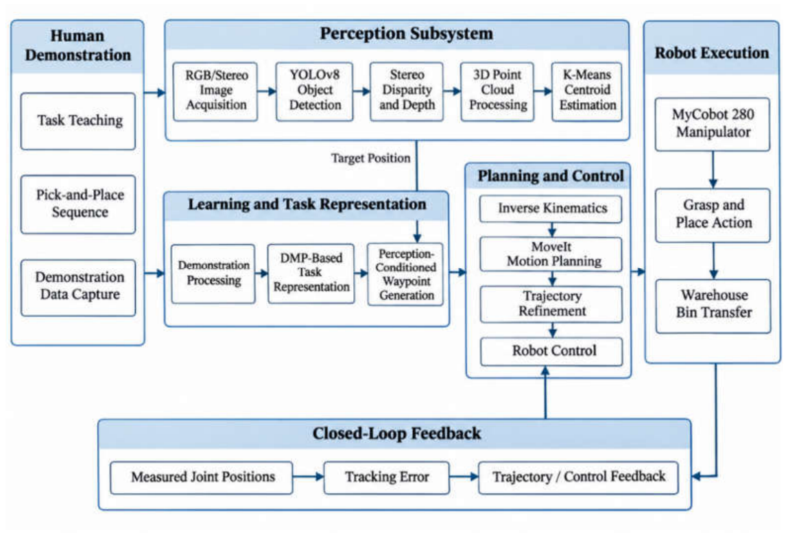
Figure 2.
Experimental SLRS platform and warehouse-based manipulation workspace: (a) robotic workspace; (b) manipulation during execution; and (c) principal experimental configuration.
Figure 2.
Experimental SLRS platform and warehouse-based manipulation workspace: (a) robotic workspace; (b) manipulation during execution; and (c) principal experimental configuration.
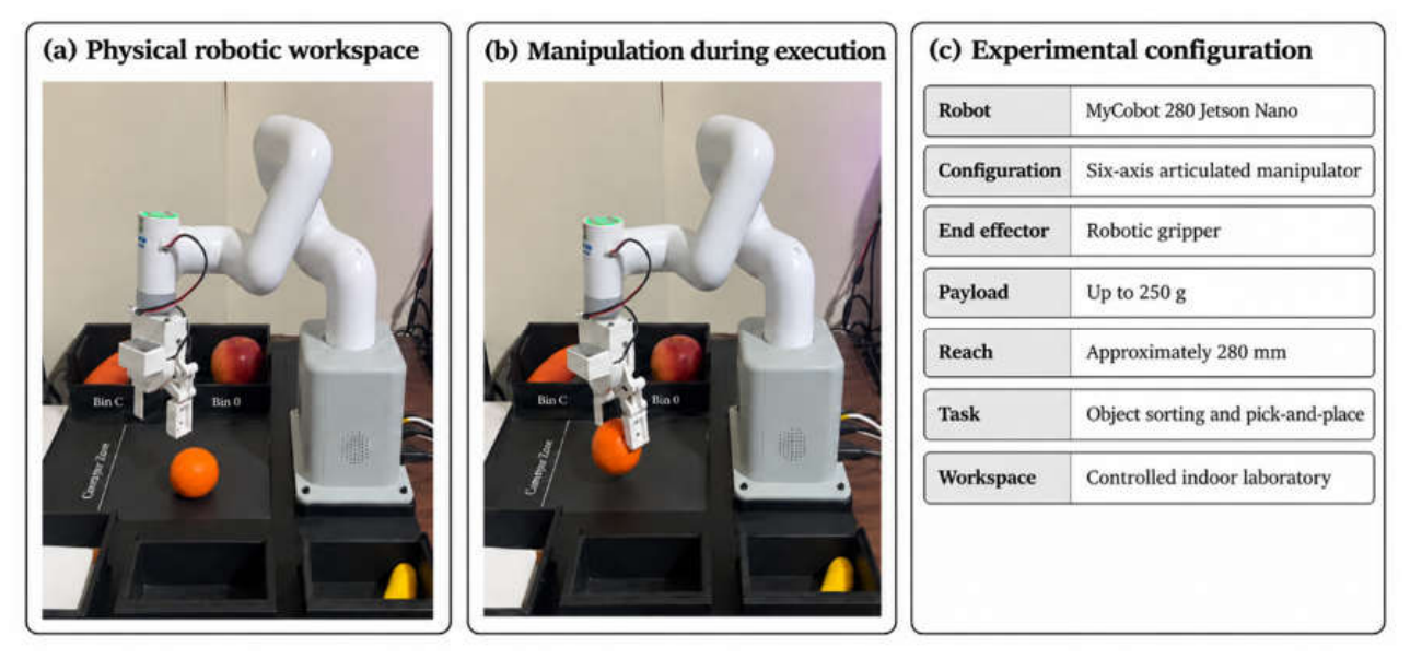
Figure 3.
Perception and three-dimensional localisation pipeline: RGB/stereo acquisition, YOLOv8 object detection, stereo disparity and depth estimation, point-cloud generation, object-region extraction, K-means clustering, and centroid transfer to the manipulation planner.
Figure 3.
Perception and three-dimensional localisation pipeline: RGB/stereo acquisition, YOLOv8 object detection, stereo disparity and depth estimation, point-cloud generation, object-region extraction, K-means clustering, and centroid transfer to the manipulation planner.
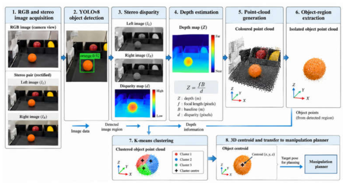
Figure 4.
Demonstration-derived manipulation workflow from task representation and target position to waypoint generation, inverse kinematics, MoveIt planning, trajectory generation, and robot execution.
Figure 4.
Demonstration-derived manipulation workflow from task representation and target position to waypoint generation, inverse kinematics, MoveIt planning, trajectory generation, and robot execution.
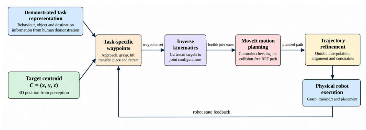
Figure 5.
Training accuracy before and after SMOTE balancing for the three evaluated training sets. The mean post-SMOTE training accuracy was 89.02%.
Figure 5.
Training accuracy before and after SMOTE balancing for the three evaluated training sets. The mean post-SMOTE training accuracy was 89.02%.
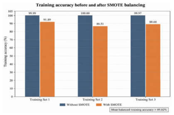
Figure 6.
Mean pick-and-place completion time for Bins A-D under non-optimised and optimised trajectory conditions; error bars represent one standard deviation across ten trials.
Figure 6.
Mean pick-and-place completion time for Bins A-D under non-optimised and optimised trajectory conditions; error bars represent one standard deviation across ten trials.
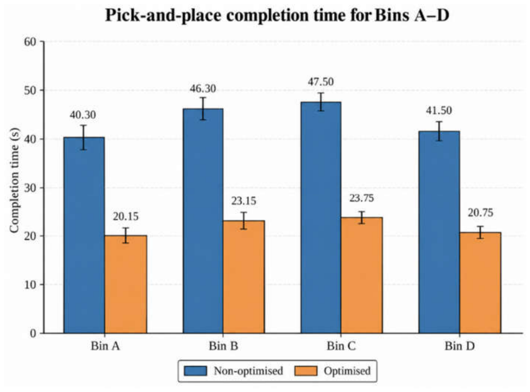
Figure 7.
Human demonstration and robot reproduction of the industrially motivated pick-and-place task. The top row shows the human demonstration sequence: (a1) initial approach, (a2) object contact, (a3) grasp, (a4) transport, and (a5) placement. The bottom row shows the corresponding robot reproduction sequence: (b1) initial approach, (b2) object alignment and contact, (b3) grasp, (b4) transport, and (b5) placement in the destination bin.
Figure 7.
Human demonstration and robot reproduction of the industrially motivated pick-and-place task. The top row shows the human demonstration sequence: (a1) initial approach, (a2) object contact, (a3) grasp, (a4) transport, and (a5) placement. The bottom row shows the corresponding robot reproduction sequence: (b1) initial approach, (b2) object alignment and contact, (b3) grasp, (b4) transport, and (b5) placement in the destination bin.
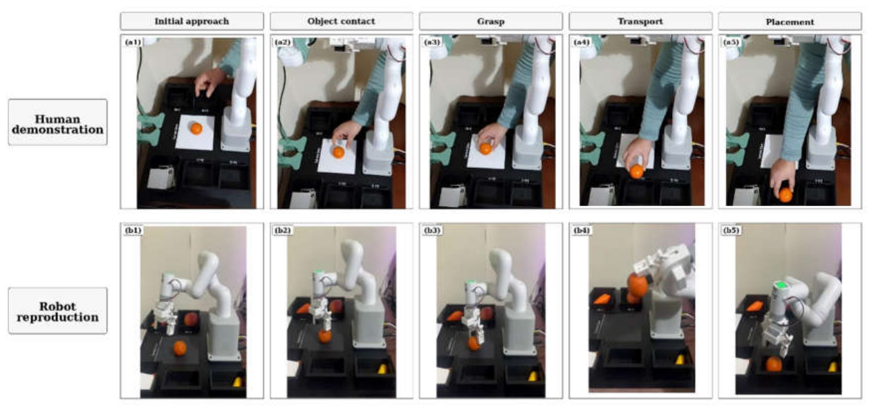

Table 1.
Principal hardware configuration of the experimental SLRS.
| Component | Experimental configuration |
| Robotic manipulator | MyCobot 280 Jetson Nano |
| Robot configuration | Six-axis articulated manipulator |
| End effector | Robotic gripper |
| Nominal payload | Up to 250 g |
| Approximate reach | 280 mm |
| Embedded computer | NVIDIA Jetson Nano |
| Vision | RGB and stereo visual sensing |
| Robot feedback | Joint position feedback |
| Communication | USB/Wi-Fi |
| Experimental task | Sorting and pick-and-place |
| Environment | Controlled indoor laboratory |
Table 2.
Training accuracy before and after SMOTE balancing.
| Training set | Without SMOTE (%) | With SMOTE (%) |
| 1 | 99.99 | 91.89 |
| 2 | 100.00 | 86.51 |
| 3 | 99.97 | 88.68 |
| Mean | 99.99 | 89.02 |
Table 3.
Trial-level recorded Pick-and-place completion times under non-optimised and optimised trajectory conditions.
Table 3.
Trial-level recorded Pick-and-place completion times under non-optimised and optimised trajectory conditions.
| Bin | Trial | Without optimisation (s) | With optimisation (s) |
| A | 1 | 40.0 | 20.0 |
| A | 2 | 42.0 | 21.0 |
| A | 3 | 39.0 | 19.5 |
| A | 4 | 41.0 | 20.5 |
| A | 5 | 38.0 | 19.0 |
| A | 6 | 37.0 | 18.5 |
| A | 7 | 40.0 | 20.0 |
| A | 8 | 43.0 | 21.5 |
| A | 9 | 44.0 | 22.0 |
| A | 10 | 39.0 | 19.5 |
| B | 1 | 45.0 | 22.5 |
| B | 2 | 48.0 | 24.0 |
| B | 3 | 46.0 | 23.0 |
| B | 4 | 44.0 | 22.0 |
| B | 5 | 47.0 | 23.5 |
| B | 6 | 43.0 | 21.5 |
| B | 7 | 45.0 | 22.5 |
| B | 8 | 49.0 | 24.5 |
| B | 9 | 50.0 | 25.0 |
| B | 10 | 46.0 | 23.0 |
| C | 1 | 47.0 | 23.5 |
| C | 2 | 49.0 | 24.5 |
| C | 3 | 46.0 | 23.0 |
| C | 4 | 48.0 | 24.0 |
| C | 5 | 50.0 | 25.0 |
| C | 6 | 45.0 | 22.5 |
| C | 7 | 47.0 | 23.5 |
| C | 8 | 46.0 | 23.0 |
| C | 9 | 48.0 | 24.0 |
| C | 10 | 49.0 | 24.5 |
| D | 1 | 42.0 | 21.0 |
| D | 2 | 41.0 | 20.5 |
| D | 3 | 43.0 | 21.5 |
| D | 4 | 40.0 | 20.0 |
| D | 5 | 39.0 | 19.5 |
| D | 6 | 41.0 | 20.5 |
| D | 7 | 42.0 | 21.0 |
| D | 8 | 44.0 | 22.0 |
| D | 9 | 40.0 | 20.0 |
| D | 10 | 43.0 | 21.5 |
Table 4.
Destination-specific descriptive statistics for pick-and-place execution.
| Destination | Without optimisation, mean ± SD (s) | With optimisation, mean ± SD (s) | Reduction (s) | Reduction (%) |
| Bin A | 40.30 ± 2.21 | 20.15 ± 1.11 | 20.15 | 50.0 |
| Bin B | 46.30 ± 2.21 | 23.15 ± 1.11 | 23.15 | 50.0 |
| Bin C | 47.50 ± 1.58 | 23.75 ± 0.79 | 23.75 | 50.0 |
| Bin D | 41.50 ± 1.58 | 20.75 ± 0.79 | 20.75 | 50.0 |
Table 5.
Overall pick-and-place performance across all 40 trials per condition.
| Metric | Without optimisation | With optimisation |
| Trials | 40 | 40 |
| Mean (s) | 43.90 | 21.95 |
| Standard deviation (s) | 3.61 | 1.80 |
| Median (s) | 44.00 | 22.00 |
| Minimum (s) | 37.00 | 18.50 |
| Maximum (s) | 50.00 | 25.00 |
| Mean absolute reduction | 21.95 s | |
| Percentage reduction | 50.0% |
Disclaimer/Publisher’s Note: The statements, opinions and data contained in all publications are solely those of the individual author(s) and contributor(s) and not of MDPI and/or the editor(s). MDPI and/or the editor(s) disclaim responsibility for any injury to people or property resulting from any ideas, methods, instructions or products referred to in the content. |
© 2026 by the authors. Licensee MDPI, Basel, Switzerland. This article is an open access article distributed under the terms and conditions of the Creative Commons Attribution (CC BY) license (http://creativecommons.org/licenses/by/4.0/).
Copyright: This open access article is published under a Creative Commons CC BY 4.0 license, which permit the free download, distribution, and reuse, provided that the author and preprint are cited in any reuse.