

Submitted:
04 November 2026
Posted:
05 November 2026
You are already at the latest version
Abstract
Conventional single-mode coupling-of-mode (COM) theory fails to describe multimode coupling between acoustic modes in surface acoustic wave (SAW) resonators. Although multimode COM theory has been reported, explicit analytical formulas for perturbed wavenumbers and rule discovery of mutual coupling effects are still insufficient. In this work, a multimode COM model considering complete coupling terms is established for periodic grating structures. The analytical expressions of perturbed wavenumbers for two-mode coupling are derived, which directly quantifies how mutual-coupling coefficients influence dispersion relations and eigen-modes near Bragg condition. Numerical investigations reveal that both coupling strength and frequency separation between modes jointly distort Bragg stop-band features. Further, finite-length IDT admittance simulations demonstrate that even weak coupling can induce observable deviations on both main-mode resonance and remote spurious responses, indicating that resonator response cannot be simply superposed by independent single-mode results. Finally, the proposed multimode COM model is applied to fit finite-element simulation results of LN/SiO2/SiC heterostructured SAW resonator. Compared with conventional single-mode COM, this model successfully reproduces spurious resonances far away from main resonance. This work provides an efficient theoretical tool for broadband modeling and spurious-mode analysis of multimode thin-film SAW resonators.
Keywords:
multimode COM
; surface acoustic wave
; resonator
1. Introduction
Surface acoustic wave (SAW) devices have been extensively employed in radio-frequency (RF) front-end systems because of their compact size, low insertion loss and steep transition. [1,2,3]. Recently, advanced piezoelectric materials and multilayer structures are applied to achieve higher electromechanical coupling and high Q value. However, these structures are easily to generate multiple acoustic modes resonances within a broad frequency range. Multimode modeling of both the main mode and spurious responses are increasingly important for device design [4,5,6].
Various numerical and analytical approaches have been developed for the analysis of SAW devices, including equivalent-circuit models, delta-function models, Green’s-function methods, finite-element methods (FEM), boundary-element methods (BEM), and coupling-of-modes (COM) theory [1,2,7,8,9]. Comparatively, COM theory provides an efficient model of wave propagation, reflection, and electromechanical transduction and has consequently become one of the most widely used modeling method for SAW resonators and filters [2,10,11,12].
In the conventional COM theory, two counter-propagating acoustic waves of main mode are considered. Their interaction in IDT is characterized by a set of parameters, typically including the acoustic velocity V, coupling coefficient k, transduction coefficient z, propagation loss, and static capacitance C0 [10,11,12,13]. Once these parameters are obtained from numerical simulations or experimental data, the electrical response of a finite-length IDT can be calculated efficiently using P matrix [2,10,14,15].
The conventional COM model is particularly successful when a single acoustic mode dominates the frequency range of interest. In practical SAW structures, however, unnecessary spurious modes may exist. Depending on the substrate, piezoelectric crystal orientation, electrodes’ size, and heterogeneous layers, these modes may include Rayleigh SAW, shear-horizontal SAW, leaky SAW, Sezawa modes, higher-order guided modes, plate modes, and other acoustic branches [3,4,5,6]. The innovation of multilayer piezoelectric structure enhances different modes because acoustic energy can be confined and guided by the thin film. Consequently, unwanted modes may generate additional resonances or conductance peaks and deteriorate the out-of-band characteristics of SAW resonators and filters. Accurate prediction of such spurious responses has therefore become an important issue in the design of filter, duplexer [5,6,16].
Several extensions of conventional COM theory have been proposed to account for physical effects that cannot be adequately represented by the basic formulas. Modified COM models have been developed for surface transverse waves and leaky SAWs, where dispersion, radiation, and energy-storage effects require additional modification [17,18,19]. More recently, extended COM approaches have been introduced to reproduce high-frequency spurious responses in advanced SAW structures [16]. These studies demonstrate that the COM theory can be effectively extended and keeps accuracy and high computational efficiency. Nevertheless, many existing approaches still modeling different acoustic branches separately. That means each mode is assumed to be independent in the propagating.
However, two modes are strongly coupled when they are closed in frequency domain and interact with each other through the periodic IDT structure. Besides, acoustic energy can be transferred between different modes. Near a coupling region, even a relatively small coupling coefficient may modify the eigenvalues of the coupling matrix and consequently change the dispersion relation and stopband characteristics. For a finite-length IDT, the mode coupling may further produce measurable changes in the admittance response, including the resonances of main mode and spurious modes. Therefore, the response of a multimode SAW resonator cannot, in general, be interpreted simply as the superposition of several independent single-mode COM responses.
Although multimode COM theory has been reported in previous literature, most existing studies only provide matrix-form eigenvalue solutions. Analytical expressions for perturbed wavenumbers under two-mode coupling, which enable direct quantitative analysis of how coupling coefficients affect dispersion and Bragg stop-band behaviors, are still lacking. Moreover, systematic quantitative investigations on how mutual-coupling and resonant frequency separation jointly shape the electrical response of resonators remain insufficient. To address these limitations, this work first establishes multimode COM equations consistent of mutual-coupling terms for periodic grating structures and derives analytical formulas of perturbed wavenumbers for the two-mode coupling situation. Next, numerical analysis is performed to investigate the distortion mechanism of dispersion curves and Bragg stop-bands induced by mutual-coupling coefficients and frequency separation. Then, admittance responses of finite-length IDTs are calculated based on the multimode P-matrix method to reveal the influence of coupling on main mode and spurious mode responses. Finally, finite-element simulation results of a LN/SiO2/SiC heterostructured SAW resonator are adopted to fit with the proposed multimode COM model, verifying its effectiveness for broadband spurious-mode characterization.
2. Multimode COM Theory
Multimode COM have been previously introduced for the analysis of spurious responses in SAW devices [21], and Huang et al. further investigated the admittance characteristics associated with two coupled SAW modes for an infinitely long IDT [22]. Even though the basis of multimode COM has been presented in prior publications, distinct from those studies, this work further derives perturbed-wavenumber solutions in mathematics for the two-mode coupled system to facilitate physical interpretation of coupling effects.
On the basis of these studies, a generalized multimode COM formulation is considered here to explicitly describe the coupling of multiple acoustic modes. For the n-th acoustic mode, the subscripts “+” and “−” denote the waves propagating in the positive and negative x directions, respectively. The corresponding multimode COM equations can be written as
together with the electric current equation:
where θu is the detuning factor of the n-th mode, and knn denotes the self-coupling or reflection coefficient between the propagating waves Un+ and Un- of the n-th mode. In contrast, the mutual coupling coefficient, knm between the n-th and m-th acoustic modes characterizes the intermodal interaction and represents the conversion of acoustic energy between different modal branches. Physically, knm is not equal to kmn. Because the former denotes the influence of m-th mode to the n-th mode, and the latter denotes the influence of n-th mode to the m-th mode, conversely. The parameter associated with electromechanical transduction describes the excitation of the n-th acoustic mode by the applied voltage v. Furthermore, i denotes the electrical current, w is the angular frequency, and C represents the static capacitance of the IDT.
An important distinction between the present multimode formulation and the conventional single-mode COM model is therefore the explicit inclusion of the mutual coupling terms. When all mutual coupling coefficients are zeros, the system is decoupled into a set of independent conventional COM equations, and each acoustic mode can be treated separately. When the mutual coupling coefficients are nonzero, however, the acoustic waves belonging to different modes become mutually coupled. Consequently, the propagation constants of the entire system are no longer determined independently by the detuning and reflection parameters of each individual mode. Instead, they are given by the eigenvalues of the complete multimode coupling system.
To clarify the influence of mutual coupling on the propagation characteristics, the solution of acoustic waves is assumed to a spatial dependence of the acoustic-wave amplitudes in the form
where An± is the amplitude of the n-th mode, the coupled differential equations can be transformed into an eigenvalue problem. As shown by the Equation (5), partial differential equations can be rewritten to matrix form, while M is the coupling matrix, U is vector consist of Un±, and I is identity matrix. In equation (6), λ is the eigenvalues of M [23]. The resulting eigenvalues determine the perturbed wavenumbers θp of the coupled acoustic system.
Physically, these perturbed wavenumbers describe the propagation and attenuation characteristics of the eigenmodes decided by the periodic IDT structure. Their real and imaginary components therefore reveal the dispersion relation and the formation of the Bragg reflection stopband, which will be discussed in next part.
For a general multimode system, the characteristic equation has a relatively high order, and an explicit analytical expression for the perturbed wavenumbers rapidly becomes cumbersome as the number of considered modes increases. To obtain an understandable physical interpretation, the following analysis focuses on the two-mode case. Then the perturbed wavenumbers can then be expressed in an analytical form as
where the auxiliary quantities A, B, C and D are defined as
respectively. While k12 or k21 is zero, equations 1 and 2 degenerate into independent single-mode equations.
The above expression explicitly relates the perturbed wavenumbers to the detuning factors, multimode reflection coefficients, and multimode coupling coefficients. Therefore, it provides a mathematical way of identifying how the interaction between two acoustic modes modifies the propagation characteristics of the periodic structure. It is notable that the eigenvalues are shifted from their uncoupled values even if k12 or k21 is zero, indicating that the propagation characteristics of one mode can be changed by the other mode even when the latter is located outside its own Bragg reflection stopband.
This result is particularly important for the explain of spurious responses in SAW resonators. A spurious mode does not necessarily need to exhibit strong Bragg reflection by itself to impact the response of the main mode. Through mutual coupling, it can perturb the eigenvalues of the coupled system and consequently change the position and width of the Bragg stopband. Conversely, the periodic structure with propagating main mode can influence the spurious mode through the same coupling mechanism. Therefore, the general dispersion characteristics should be regarded as those of the coupled eigenmodes rather than those of two completely independent acoustic branches.
3. Dispersion Characteristics of Two Coupled Acoustic Modes
In this section, the influence of coupling coefficients on the dispersion characteristics of two acoustic modes is investigated graphically and show that how k value changes the shape of Bragg reflection and resonant frequency. There are points are discussed: (1) how the mutual coefficients, k12 and k21, change the stop band; (2) the stopband distortion caused by coupling when the frequencies of two acoustic modes become close; (3) the special case when k12 and k21 are zero.
3.1. Mutual Coupling
For simplification, the mutual coupling coefficients, k12 and k21, are assumed to be equal in the discussion, while reflection coefficients are fixed at k11= k22=0.03π. Frequency of waves is normalized. Besides, fc1 and fc2 are used to indicate the central frequency of first mode and second mode respectively.
Firstly, k12 and k21 is set to zero in calculation. The Bragg stopbands of two modes are separated, as shown as Figure 1a. Left one (blue) is the first mode and right one (red) is the second mode. It is clear that there is no coupling between two modes.
When the mutual coupling coefficients are increased to k12= k21=0.01π, as shown in Figure 1b, the dispersion characteristics around the intersection of the two branches are connected. Instead of crossing directly, the two branches have the same complex eigen values in the black region of the original intersection. In this coupling region, the two acoustic modes exchange their energy.
A stronger coupling is observed when the coupling coefficients are further increased to k12= k21=0.02π, as shown in Figure 1c,d. The separation between the two dispersion branches becomes more significant, while the perturbation extends over a wider frequency range. Comparison of Figure 1 indicates that the magnitude of the mutual coupling coefficient directly determines the strength of the coupling between the two dispersion branches. In addition, the stopbands are changed as well. The stopband of low-frequency mode becomes wider while another one becomes narrow. Both of central frequencies are moved far away from each other. This is an important effect of mutual coupling coefficient, k12 and k21.
From the view of eigenvalue, the mutual coupling terms are off-diagonal elements in the COM matrix. When two uncoupled eigenvalues approach each other, these off-diagonal terms lift their degeneracy and uncrossing the dispersion curves. Therefore, the separation of the coupled branches increases with the strength of the multimode coupling. These results provide a direct physical interpretation of the coupling coefficient in the multimode COM formulation. The reflection coefficients k11 and k22 mainly determine the Bragg reflection characteristics of their corresponding modes, while k12 and k21 control the mutual coupling and energy conversion between different acoustic branches and also change the dispersion characteristics.
3.2. Nearby Coupling
The coupling becomes more complicated when the Bragg frequencies of the two modes move closer each other. To investigate this case, the center frequency of mode 1 is maintained at the normalized frequency fc1=1.0, and the center frequency of mode 2 is progressively shifted toward that of mode 1, keeping k12=k21=0.02p simultaneously.
Figure 2a presents the dispersion characteristics when the center frequency of mode 2 is fc2=1.1. Compared with the cases considered in the previous section, the two Bragg regions are now located closer to each other. The dispersion branches associated with the individual stopbands consequently interact more strongly, and the width of stop band become larger (left blue mode) or smaller (right red mode).
When fc2 is further reduced to 1.05, as shown in Figure 2b, the two Bragg regions become sufficiently close that their dispersion characteristics can no longer be interpreted as two isolated stopbands. The stopbands are in severe distortion caused by coupling.
The comparison between Figure 2a,b demonstrates that the frequency separation between the two acoustic modes is an important factor governing the observable strength of multimode interaction. For a given mutual coupling coefficient, decreasing the frequency separation between two modes enhances the perturbation. In Figure 2c, two modes become closer. There is no enough coupling space between two branches and the mode conversion is quite blurred. Because of mutual coupling, the central frequency of two could not be equal, as calculated by Figure 2d. It is notable that these two modes possess the same reflection coefficients, k12=k21 namely. If fc2 further reduces to less than 1.0, their positions will exchange.
This behavior has practical implications for multimode SAW resonators. A parasitic mode located far from the main may cause only a localized perturbation of the dispersion characteristics. As its frequency approaches the Bragg region of the main mode, however, the same coupling strength can produce stronger impact of the coupled dispersion branches. The frequency separation between the desired and parasitic modes should therefore be considered together with the multimode coupling coefficients when evaluating their influence on device characteristics.
3.3. Single Coupling
The preceding analysis assumes reciprocal symmetric coupling with k12= k21. To further examine the mathematical role of the two coupling terms, an asymmetric case is considered by setting k12=0.03π and k21=0, while maintaining the reflection coefficients of the two modes (k11= k22=0.03π).
In equation 13, it is known that D term will be zero if k12=0 or k21=0. Hence, as long as k12 or k21 is zero, the mutual coupling becomes zero as well.
Figure 3a shows the calculated dispersion curves when the frequencies of two modes are relatively far apart. Coupling region disappear due to k21=0. Figure 3b presents the corresponding result when the two modes are set closer together. The Bragg regions approach each other, but the dispersion remains independent and different from that obtained in symmetric mutual coupling. The absence of the coupling term k21 changes the structure of the equation as well. Consequently, the resulting perturbed wavenumbers are decoupled. This comparison indicates that the perturbed wavenumbers depend on the combination of all mutual coupling terms rather than on a single coefficient alone.
For a reciprocal and lossless physical SAW structure, the mutual coupling coefficients are generally subject to reciprocity and energy-conservation constraints. Therefore, k12 and k21 should not necessarily be regarded as two completely independent parameters in a physical device. The relationship between the coupling coefficients in a physically reciprocal system should be determined according to the corresponding reciprocity conditions.
Overall, the results of this section demonstrate that the dispersion characteristics of a multimode SAW system are governed jointly by the reflection coefficients, mutual coupling coefficients, and frequency separation between the modes. Mutual coupling produces pronounced interaction between otherwise crossing dispersion branches, and the interaction becomes progressively stronger as the two modal frequencies approach each other. These changes in the perturbed wavenumbers provide the basis for understanding how multimode coupling subsequently contribute to the electrical response of a finite-length IDT.
4. Mutual Coupling on the Admittance Response
A two-modes SAW resonator is considered in the following admittance analysis. The IDT contains 100 electrodes and each reflector consists of 30 electrodes. The pitch of the IDT is normalized, and the resonance frequency associated with the main mode is approximately 2290 MHz. The response of the complete resonator is calculated using the multimode P-matrix formulation. In this representation, the acoustic waves belonging to different modes are simultaneously propagated through the IDT and reflector sections, allowing both reflection and modes’ conversion to be included in the finite-length device response.
4.1. Remote Mode
A secondary acoustic mode located at approximately normalized frequency ~1.09 is first introduced, while the dominant resonance remains around 1.0. The electromechanical transduction coefficient of the main mode is set to 0.06, whereas that of the secondary mode is set to 0.001. The reflection coefficient of the main mode is k11=0.03p, while that of the secondary mode is set to k22=0.03p as well.
Figure 4 shows the calculated admittance response with different coupling strengths. When the mutual coupling coefficients are zero, the two acoustic modes are effectively independent. The main resonance is predominantly determined by the COM parameters of mode 1, while the response near 1.09 originates mainly from the weak electromechanical excitation of mode 2. It is notable that there is a response locates at 1.06, which is the cut-off peaks of main mode.
As the mutual coupling coefficient increases, noticeable frequency shifts appear. In particular, the resonance and antiresonance frequencies of main mode are shifted, indicating that a remote secondary mode can perturb the effective resonance condition of the main mode through mutual coupling. Meanwhile, the response around the secondary mode is also changed. This observation is important because it indicates that a spurious response does not necessarily originate only from the its own electromechanical excitation and Bragg reflection of the corresponding parasitic mode. Acoustic energy transferred from the main mode through coupling can also contribute to the observable secondary response.
The separation between the main resonance and spurious resonance also increased with increasing mutual coupling. This trend is consistent with the calculation in section 3.1. The result suggests that coupling of modes may change the characteristics of the main mode. Therefore, when a conventional single-mode COM model is used to fit a multimode resonator, part of the effect caused by a remote coupled mode may be incorrectly absorbed into the fitted single-mode COM parameters.
4.2. Nearby Mode
The influence of mutual coupling becomes considerably stronger when the secondary acoustic mode approaches the main resonance. To examine this situation, the resonant frequency of the secondary mode is set at 1.01 (normalized frequency), while the main mode remains at 1.0. Thus, the frequency separation between the two modes is so closed.
Figure 5 shows the corresponding admittance response for different mutual coupling coefficients. Compared with the remote-mode case, variations in the coupling coefficient now produce much stronger impact around the main resonance region. Both the two modes become increasingly sensitive to the coupling strength. It can be understood from the perturbed-wavenumber analysis in Section 3. When the uncoupled modes are well separated, the perturbation induced by the off-diagonal coupling terms remains limited. As the two modes approach each other, the difference between the uncoupled eigenvalues decreases. The same coupling coefficient can therefore produce a much larger perturbation of the coupled eigenvalues. The stopband of main mode, with lower frequency, becomes wider and that of spurious mode becomes smaller. Frequencies are shifted as well.
Comparison of the remote- and nearby-mode cases further demonstrates that the significance of mutual coupling is controlled by both the magnitude of the coupling coefficient and the spectral separation between the modes. A relatively large coupling coefficient may produce only a modest perturbation when the modes are sufficiently separated, whereas a considerably smaller coefficient may become important when the resonant frequencies are close. Consequently, the frequency position of a spurious mode should be considered together with its coupling strength when evaluating its influence on a practical SAW resonator.
4.3. Single Coupling
The preceding calculations assume symmetric mutual coupling between the two acoustic modes (k12= k21). To further clarify the function roles of these two off-diagonal coupling terms, the remote mode configuration, often seen in practical design, is used to investigate with different values of k12 and k21. The calculated admittance responses are presented in Figure 6.
When only one of the two coupling terms produces a response that differs from the case in which both coupling coefficients are simultaneously nonzero. It is clear that resonant frequencies are not changed due to another term is zero. This behavior is consistent with the eigenvalue analysis of the two-mode COM system, in which the impact of the perturbed wavenumbers is governed by the combined contribution of the off-diagonal coupling terms. However, antiresonance of main mode shifts to higher frequency. It is attributed to the electric coupling but not mechanical coupling.
It should also be emphasized that the zero coupling cases considered here are primarily introduced to examine the mathematical roles of k12 and k21 separately. Arbitrary asymmetric values should therefore not be interpreted as a general physical condition for reciprocal SAW devices. Besides, responses of remote spurious are usually smaller than main mode. Hence, the mutual coupling coefficients are negligible.
Generally, the finite-length resonator calculations demonstrate that mutual coupling influences not only the dispersion characteristics but also the electric response. A remote secondary mode can perturb the main resonance and generate observable spurious features through mode conversion, while a nearby mode produces substantially stronger impact because of the reduced frequency separation. These results indicate that multimode coupling should be explicitly considered when broadband responses, particularly remote spurious resonances, cannot be adequately reproduced using a conventional single-mode COM model.
5. Validation by Heterostructured SAW Resonator
This work focuses on theoretical modeling and mechanism verification of the multimode COM approach. Validated finite-element method simulation data are utilized as the sample, instead of physical device measurements. Fabrication and experimental testing of real devices will be considered in future research.
Hence, to further evaluate the applicability of the proposed multimode COM model, the formulation developed in the preceding sections is applied to the measured response of a heterostructured SAW resonator. Thin film of 40o-X cut lithium niobate on SiO2/SiC substrate is chosen in our research. This type of device work with high velocity and high Q value. Energy is trapped on surface so that spurious modes also have strong responses. This is a good sample for the validation of multimode COM theory. A model with 100 IDT fingers and 30 reflector fingers is built by finite element method, while the thickness of LN and SiO2 is both 200nm. Period of IDT is 800nm. This is a high frequency design as an important topic recently [24].
By fitting multiple acoustic modes, the calculated response exhibits significantly improved agreement with the measured broadband characteristics, as shown in Figure 7a,b. It is notable that infinite multimode COM [22] is employed as comparison. There are 4 modes in the admittance curve. First mode is the main mode. According to the previous analysis in section 4.3, k21 is set to nonzero to reduce the impact to main mode, while k12 is set to zero and characterized the influence of main mode to the second mode. Simultaneously, other mutual coupling coefficients are set to zero as far away from the main mode. It is markable that detail acoustic vibration field is not our topic, and not discussed herein as well.
The COM parameters used in calculation are listed in Table 1. The transduction coefficients of modes decrease as their distance to main mode increases. However, there is a strong signal (mode 2) locates at the cutoff region of main mode. Some ripples are easily observed in stopband at around 5500MHz. This is caused by the stopband of mode 2. One solution is to use shunt resonant arm in fitting [14].
From the view of result, the proposed model can serve as an efficient tool for broadband response fitting, multimode parameter extraction, and analysis of spurious modes in practical SAW resonators.
The fitting result also illustrates an important distinction between the proposed approach and a simple combination of several independent single-mode COM responses. If each spurious resonance were modeled independently, additional single-mode branches could generate independent spectral features, but the coupling among the acoustic modes would be neglected. In the multimode COM formulation, the calculated response simultaneously contains the intrinsic propagation and reflection of each mode, their electromechanical excitation, and the conversion of acoustic energy between different modal branches.
In summary, the experimental fitting shown in Figure 7 provide practical validation of the multimode COM theory developed in this work. The model reproduces not only the main resonance but also spurious responses located away from the main resonance region, demonstrating its capability for broadband characterization of thin-film heterolayer resonators. Combined with the perturbed-wavenumber analysis in Section 3 and the finite-length resonator simulations in Section 4, the experimental result confirms that multimode coupling equations provides an important method to connect multimode dispersion characteristics and observable spurious responses.
6. Discussion
Our results reveal that two major physical effects of multiple modes coupling: the broadening or narrowing of Bragg stopband and frequency repulsion of coupled eigen modes. Even spurious modes located far from the main resonance, they can perturb the main mode via acoustic energy conversion, so the resonator response cannot be regarded as simple combination of several independent single-mode COM results. The essential contribution of this work is the explicit inclusion of all coupling terms in perturbed wavenumber analysis. In the absence of such coupling, the governing equations are reduced to independent conventional COM systems, and each acoustic mode retains its own dispersion relation and Bragg reflection characteristics. Once the mutual coupling terms imported, however, the propagation constants are determined by the eigenvalues of the complete coupled system. The perturbed wavenumbers derived in this work therefore provide a direct connection between the COM coupling parameters and the dispersion characteristics of coupled acoustic modes.
The two-mode analysis further shows that the influence of mutual coupling depends jointly on the coupling strength and the spectral separation between the modes:
(1) Mutual coupling, k12 and k21, makes the Bragg stopbands away from each other with distortion. Further, the mode with lower frequency has wider band, while another mode with higher frequency has narrower band.
(2) When either k12 or k21 is set to zero, single coupling namely, the modes would be decoupled basically in acoustics.
(3) Coupling becomes stronger while the spurious mode gets closer to the main modes if there is any coupling exist.
(4) Single coupling (k12=0 or k21=0) gets smaller impact to electric response of main mode than joint coupling (k12≠0 and k21≠0).
The theoretical resonator calculations and the experimental fitting of a LN/SiO2/SiC SAW resonator support this interpretation. The multimode COM model is particularly relevant to broadband characterization, while the conventional single-mode model may accurately reproduce the main resonance but fail to account for additional modes. Rather than introducing each spurious resonance as an independent response, the multimode formulation describes the acoustic branches and their interactions within one matrix equation.
However, increasing the number of modes can improve the flexibility of broadband fitting but also increase additional parameters and may increase the difficulty of parameter extraction. Future work should consequently focus on establishing robust procedures for extracting each coupling coefficients from numerical or experimental dispersion data.
7. Conclusion and Future Work
A multimode COM theory has been investigated for the analysis of multiple acoustic modes in SAW resonators. By explicitly import mutual coupling terms into the conventional COM equations, the model describes both the forward and backward propagating interaction within each acoustic mode and the coupling between different acoustic modes. Next, an analytical expression for the perturbed wavenumbers was obtained, providing a direct relationship between the multimode COM parameters and the dispersion characteristics of the coupled acoustic system.
The two-mode analysis showed that mutual coupling changes the perturbed wavenumbers and the corresponding dispersion branches. The coupling strength increases with larger mutual coupling, k12 and k21, or smaller frequency separation between the modes. The results also showed that the k12 and k21 jointly determine the eigenvalue characteristics of the coupled system. These observations provide a physical interpretation of how coupling affects the Bragg reflection region and the propagation characteristics of multimode periodic SAW structures.
The analysis was subsequently extended to finite-length SAW resonators. The calculated admittance responses demonstrated that mutual coupling can influence both the main resonance and the spurious responses. A secondary mode located far from the main resonance can still produce an observable contribution through the mode conversion within the finite IDT, whereas a nearby secondary mode produces considerably stronger impact to the resonator response.
Finally, the multimode COM model was applied to the simulation response of a LN/SiO2/SiC SAW resonator. The model reproduced the main resonance together with spurious responses located away from the main resonance region, demonstrating its potential for broadband response fitting beyond the capability of a conventional single-mode COM.
The proposed multimode COM theory thus provides an efficient approach for investigating mode coupling, analyzing spurious responses, and performing broadband characterization of SAW resonators. Further development of parameter-extraction methods and extension to multimode systems may enrich its application to increasingly complex high-performance SAW devices.
Acknowledgments
This work is supported by Natural Science Project of Guangdong University of Science and Technology (XJ2025001503).
References
- Morgan, D. Surface Acoustic Wave Filters: With Applications to Electronic Communications and Signal Processing, 2nd ed.; Academic Press, 2007. [Google Scholar]
- Hashimoto, K.-Y. Surface Acoustic Wave Devices in Telecommunications: Modelling and Simulation; Springer, 2000. [Google Scholar]
- Campbell, C. Surface Acoustic Wave Devices for Mobile and Wireless Communications; Academic Press, 1998. [Google Scholar]
- Plessky, V.P.; Koskela, J. Coupling-of-modes analysis of SAW devices. Int. J. High Speed Electron. Syst. 2000, 10(4), 867–947. [Google Scholar] [CrossRef]
- Suzuki, Y.; Takeuchi, M.; Nakamura, K.; Hirota, K. Coupled-mode theory of SAW periodic structures. Electron. Commun. Jpn. 1993, 76(6), 87–98. [Google Scholar] [CrossRef]
- Chen, Z.H.; Takeuchi, M.; Yamanouchi, K. Analysis of the film thickness dependence of a single-phase unidirectional transducer using the coupling-of-modes theory and the finite-element method. IEEE Trans. Ultrason. Ferroelectr. Freq. Control 1992, 39, 82–94. [Google Scholar] [CrossRef]
- Plessky, V.P. A two-parameter coupling-of-modes model for shear horizontal type SAW propagation in periodic gratings. Proc. IEEE Ultrason. Symp. 1993, 195–200. [Google Scholar] [CrossRef]
- Hashimoto, K.-Y.; Yamaguchi, H.; Yamaguchi, M. General-purpose simulator for leaky surface acoustic wave devices based on coupling-of-modes theory. Proc. IEEE Ultrason. Symp. 1996, 117–122. [Google Scholar]
- Abbott, B.P.; Hashimoto, K.-Y.; et al. A coupling-of-modes formalism for surface transverse wave devices. Proc. IEEE Ultrason. Symp. 1995, 239–245. [Google Scholar]
- Hashimoto, K.-Y.; Endoh, G.; Yamaguchi, M.; et al. Coupling-of-modes modelling for fast and precise simulation of leaky surface acoustic wave devices. Proc. IEEE Ultrason. Symp. 1995, 251–256. [Google Scholar]
- Ventura, P.; Hodé, J.M.; Solal, M. A new efficient combined FEM and periodic Green’s function formalism for the analysis of periodic SAW structures. Proc. IEEE Ultrason. Symp. 1995, 263–268. [Google Scholar]
- Hashimoto, K.-Y.; Omori, T.; Yamaguchi, M. Design considerations on surface acoustic wave resonators with significant internal reflection in interdigital transducers. IEEE Trans. Ultrason. Ferroelectr. Freq. Control 2004, 51(11), 1394–1403. [Google Scholar] [CrossRef]
- Hashimoto, K.-Y.; Bao, J.-F. First-order perturbation analysis of nonlinear signal generation in surface acoustic wave resonators on LiTaO3/SiO2/Si structure based on coupling-of-modes theory. IEEE Trans. Ultrason. Ferroelectr. Freq. Control 2022, 69(11), 3203–3210. [Google Scholar] [CrossRef]
- Jiang, G.; Shuai, Y.; Wei, Z.; Yao, J.; Luo, W.; Pan, X.; Wu, C.; Zhang, W. Modeling for High-Frequency Spurious Responses in Incredible High-Performance Surface Acoustic Wave Devices. Micromachines 2024, 15(1), 134. [Google Scholar] [CrossRef]
- Ma, X.; Lei, H.; Cai, P.; Ji, X. Fast Extraction of Coupling of Modes Parameters for Surface Acoustic Wave Devices Using Finite Element Method Based Simulation. Appl. Sci. 2022, 12(9), 4547. [Google Scholar] [CrossRef]
- Yang, B.; Gao, L.; Lu, W. Study of coupling-of-modes for wavelet transform processors using surface acoustic wave devices. Microelectron. J. 2023, 131, 105644. [Google Scholar] [CrossRef]
- Boyanov, B.I.; et al. COM-theory analysis of STW resonator structures. Proc. IEEE Ultrason. Symp. 1995, 317–320. [Google Scholar]
- Hashimoto, K.-Y.; Yamaguchi, M. Precise simulation of surface transverse wave devices by discrete Green function theory. Proc. IEEE Ultrason. Symp. 1994, 253–258. [Google Scholar] [CrossRef]
- Fang, X.; Sun, M.; et al. Low-Loss Longitudinal Leaky SAW Filter with 1350 MHz Bandwidth on LiNbO3/SiO2/SiC Platform for Wi-Fi 7. IEEE MTT-S Int. Microw. Symp., 2025. [Google Scholar]
- Goto, R.; Nakamura, H.; Hashimoto, K.-Y. Spurious free TC-SAW duplexer using the SiO2/LiNbO3 structure. Proc. IEEE Int. Ultrason. Symp. 2019, 2075–2078. [Google Scholar] [CrossRef]
- Goto, R.; Fujiwara, J.; Nakamura, H.; Hashimoto, K.-Y. Multimode coupling of modes model for spurious responses on SiO2/LiNbO3 substrate. Jpn. J. Appl. Phys. 2018, 57, 07LD20. [Google Scholar] [CrossRef]
- Huang, Y.; Bao, J.; Li, X.; et al. Influence of Coupling Between Rayleigh and SH SAWs on Rotated Y-Cut LiNbO3 to Their Propagations. IEEE Trans. Ultrason. Ferroelectr. Freq. Control 2018, 65(10), 1905–1913. [Google Scholar] [CrossRef]
- Mayer, M.; Ammann, S.; Pernpeintner, M.; et al. Multi-Mode P-Matrix Models for the Description of Interacting Modes in TCSAW and LSAW Devices. IEEE Int. Ultrason. Symp. 2018. [Google Scholar] [CrossRef]
- Xiaoli, F.; Jinbo, W.; Pengcheng, Z. Vertically-Excited High-Order Guided Shear Vertical Surface Acoustic Wave Resonators for 5G and Beyond. J. Microelectromechanical Syst. 2026, 301–311. [Google Scholar] [CrossRef]
Figure 1.
Dispersion curve of perturbed wavenumber with k11=k22=0.03π. Solid line is real part and dash line is imaginary part. Blue line indicates the first mode and red indicates another mode. (a) k12= k21=0; (b) k12= k21=0.02π; (c) k12= k21=0.03π; (d) k12= k21=0.04π;.
Figure 1.
Dispersion curve of perturbed wavenumber with k11=k22=0.03π. Solid line is real part and dash line is imaginary part. Blue line indicates the first mode and red indicates another mode. (a) k12= k21=0; (b) k12= k21=0.02π; (c) k12= k21=0.03π; (d) k12= k21=0.04π;.
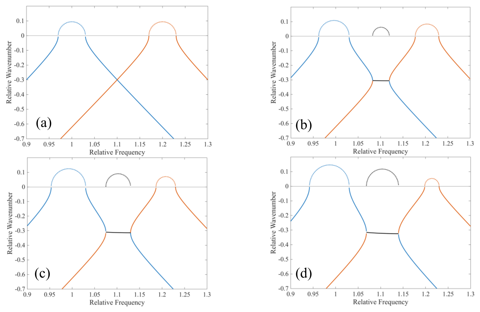
Figure 2.
Dispersion curve of perturbed wavenumber with k12= k21=0.02π, when two modes are closed. Central frequency of second mode is (a) fc2=1.1; (b) fc2=1.05; (c) fc2=1.02; (d) fc2=1.0.
Figure 2.
Dispersion curve of perturbed wavenumber with k12= k21=0.02π, when two modes are closed. Central frequency of second mode is (a) fc2=1.1; (b) fc2=1.05; (c) fc2=1.02; (d) fc2=1.0.
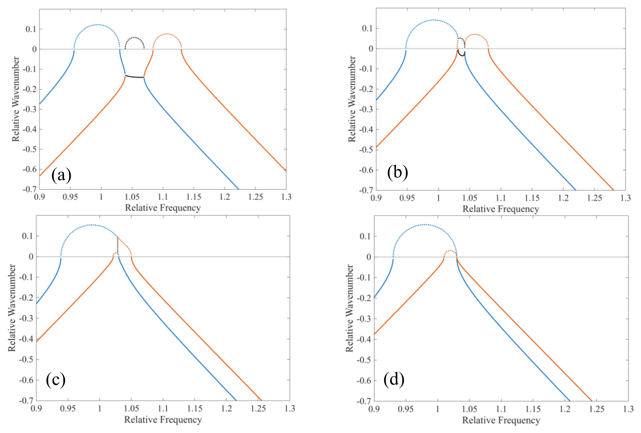
Figure 3.
Dispersion curve of perturbed wavenumber (k12=0.03π, k21=0), two modes are far away from each other with different separation: (a) fc1=1.0, fc2=1.2; (b) fc1=1.0, fc2=1.05.
Figure 3.
Dispersion curve of perturbed wavenumber (k12=0.03π, k21=0), two modes are far away from each other with different separation: (a) fc1=1.0, fc2=1.2; (b) fc1=1.0, fc2=1.05.
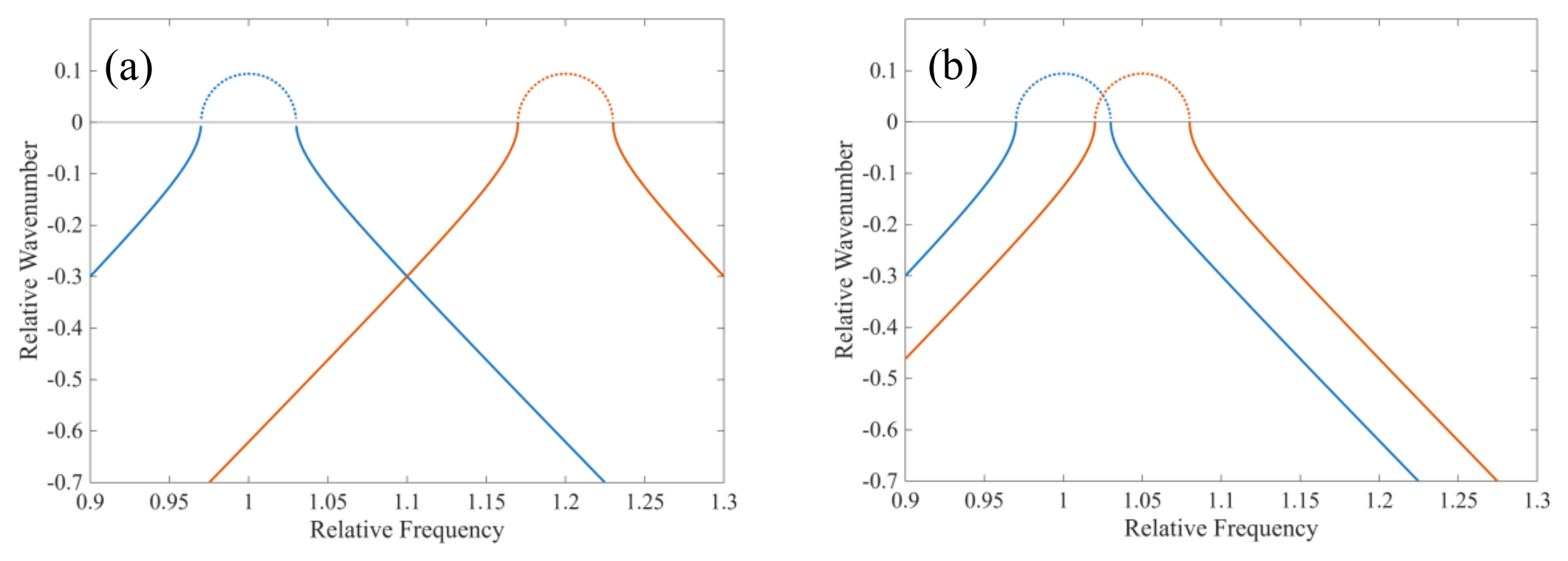
Figure 4.
Admittance curve with different mutual coupling coefficients, while second mode far away from main mode. (a) Admittance Curve and (b) Conductance Curve.
Figure 4.
Admittance curve with different mutual coupling coefficients, while second mode far away from main mode. (a) Admittance Curve and (b) Conductance Curve.
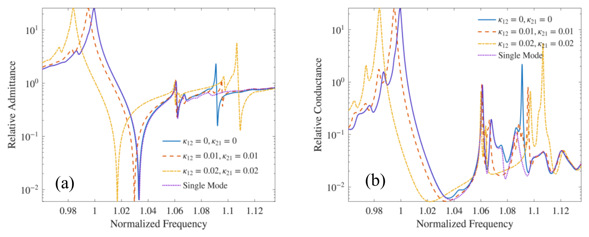
Figure 5.
Admittance curve with different mutual coupling coefficients, while second mode is closed to the main mode.
Figure 5.
Admittance curve with different mutual coupling coefficients, while second mode is closed to the main mode.
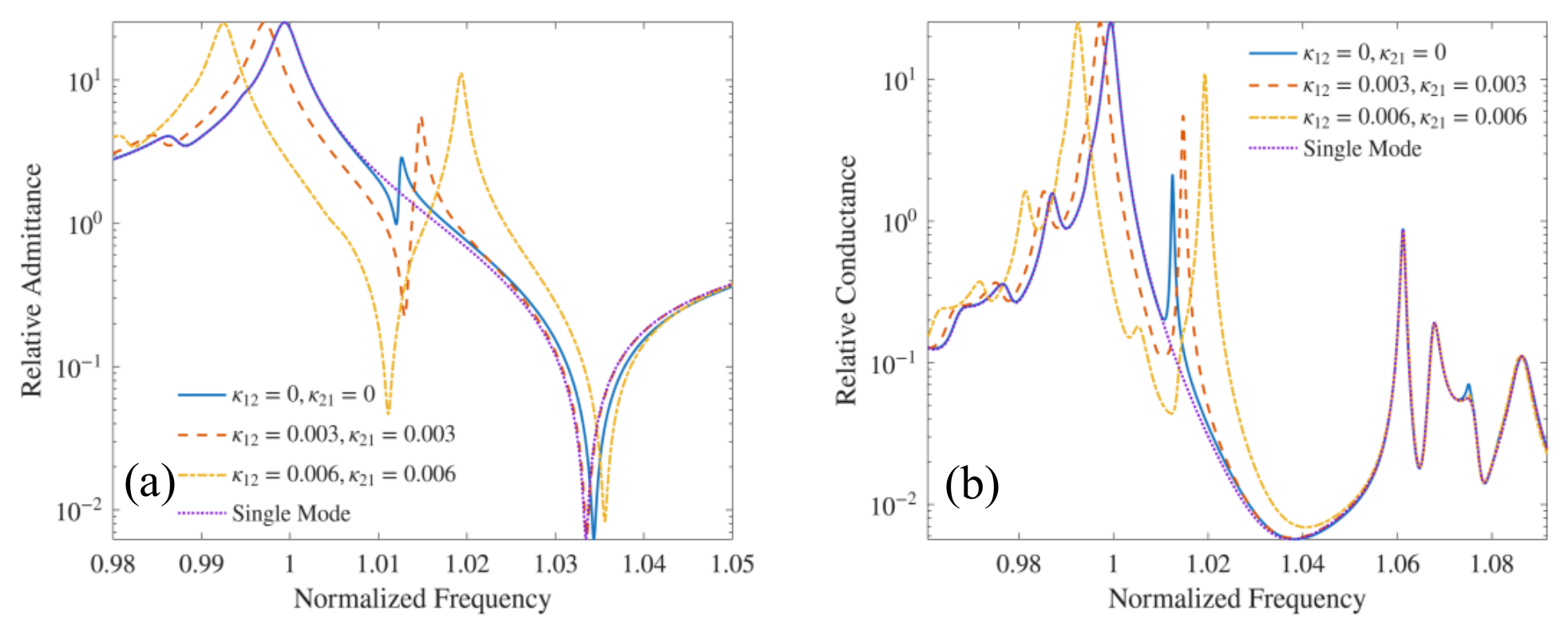
Figure 6.
Admittance curve with different mutual coupling coefficients k12 and k21 respectively.
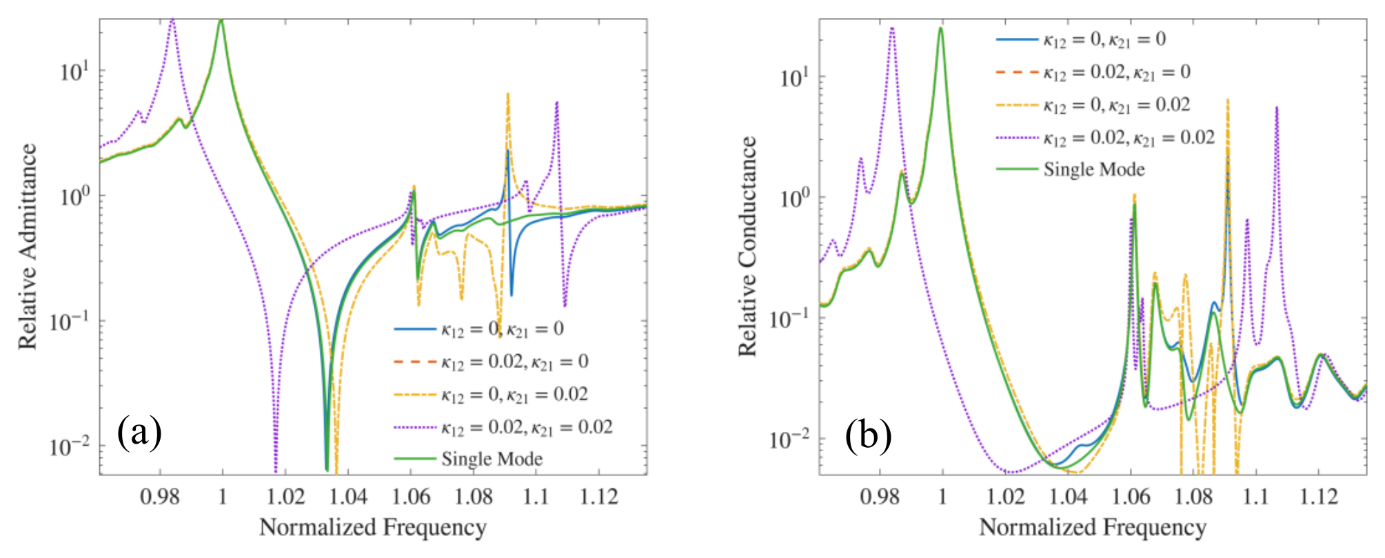
Figure 7.
Fitting of resonator’s responses by multimode COM with finite grating. Black line is FEM simulation and blue line is calculated by multimode COM. (a) Finite COM and (b) Infinite COM.
Figure 7.
Fitting of resonator’s responses by multimode COM with finite grating. Black line is FEM simulation and blue line is calculated by multimode COM. (a) Finite COM and (b) Infinite COM.
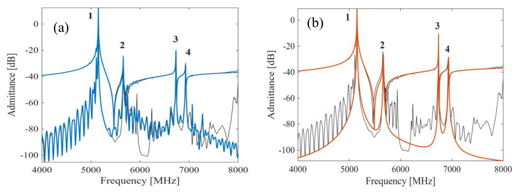

Table 1.
Parameters Used in Calculation.
| Symbol | Note | Value |
| z1 | Transduction coefficient of main mode | 0.0377 |
| z2 | Transduction coefficient of 2nd mode | 0.0016 |
| z3 | Transduction coefficient of 3rd mode | 0.0009 |
| z4 | Transduction coefficient of 4th mode | 0.0005 |
| k11 | Coupling coefficient of main mode | 0.0518 |
| k21 | Coupling coefficient of main mode | 0.0045 |
| k22 | Coupling coefficient of 2nd mode | 0.0216 |
| k33 | Coupling coefficient of 3rd mode | 0.0233 |
| k44 | Coupling coefficient of 4th mode | 0.0233 |
Disclaimer/Publisher’s Note: The statements, opinions and data contained in all publications are solely those of the individual author(s) and contributor(s) and not of MDPI and/or the editor(s). MDPI and/or the editor(s) disclaim responsibility for any injury to people or property resulting from any ideas, methods, instructions or products referred to in the content. |
© 2026 by the authors. Licensee MDPI, Basel, Switzerland. This article is an open access article distributed under the terms and conditions of the Creative Commons Attribution (CC BY) license (http://creativecommons.org/licenses/by/4.0/).
Copyright: This open access article is published under a Creative Commons CC BY 4.0 license, which permit the free download, distribution, and reuse, provided that the author and preprint are cited in any reuse.