

Submitted:
02 November 2026
Posted:
04 November 2026
You are already at the latest version
Abstract
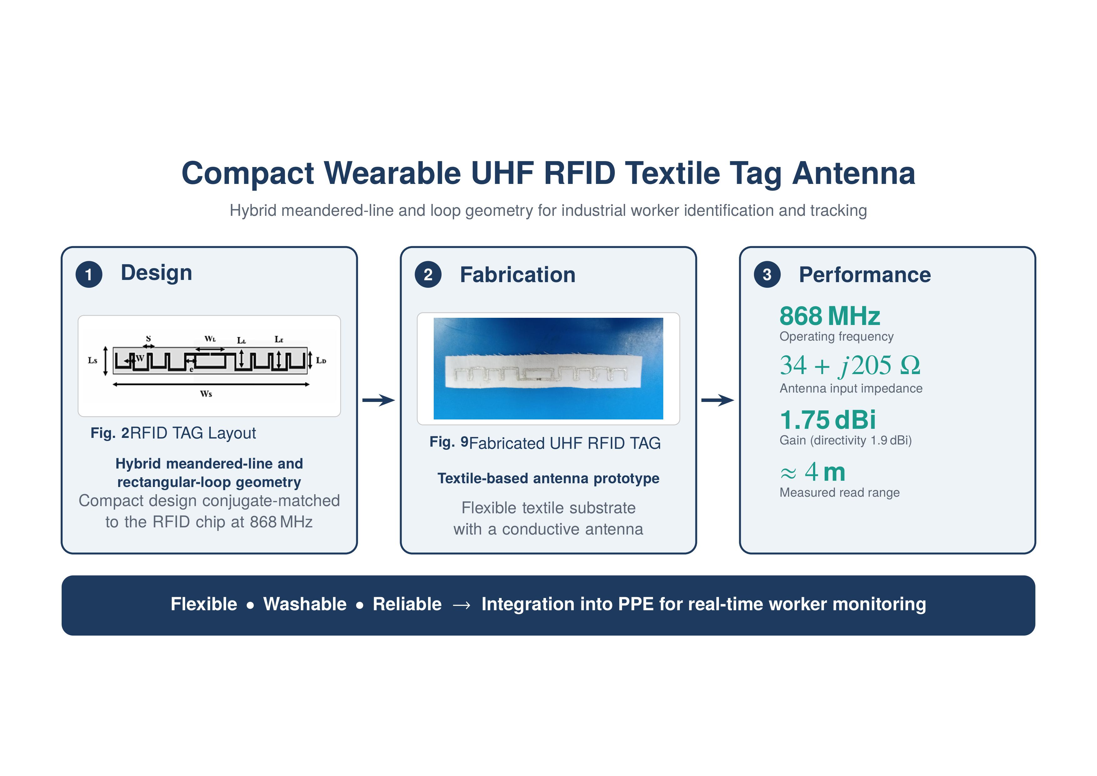
This paper presents the design, fabrication, and experimental validation of a compact wearable UHF RFID tag integrated onto a superhydrophobic textile substrate for industrial worker identification and tracking. The proposed antenna combines a meander-line structure with a rectangular loop to achieve a small form factor while maintaining robust electromagnetic performance. Electromagnetic simulations demonstrate that the antenna exhibits an input impedance of 34 + j 205 Ω at 868 MHz, closely matching the complex conjugate of the Alien Higgs-3 microchip, and achieves a gain of 1.75 dBi with a directivity of 1.9 dBi. Fabrication was performed using inkjet printing with conductive inks, and the microchip was mounted with a conductive adhesive. Experimental measurements confirm a read range of approximately 4 m under a standard test setup, in good agreement with theoretical predictions. The proposed design demonstrates high reliability, flexibility, and washability, making it suitable for integration into personal protective equipment (PPE) for real-time worker monitoring in industrial environments.
Keywords:
UHF RFID
; wearable antenna
; textile antenna
; meander-line antenna
; loop antenna
; impedance matching
1. Introduction
In recent years, ultra-high frequency (UHF) radio-frequency identification (RFID) technology has been widely adopted in industrial clothing and textile systems due to its long read range, low cost, and capability for simultaneous multi-tag identification. Operating in the 860–960 MHz band, UHF RFID enables reliable, contactless tracking of garments in large-scale industrial environments such as manufacturing sites, construction areas, and critical infrastructure facilities. The integration of UHF RFID tags into textile-based personal protective equipment (PPE) provides an effective solution for real-time worker identification, access control, and accident prevention, particularly in high-risk and high-security industrial scenarios.
This paper proposes a novel solution for industrial applications based on wearable UHF RFID textile systems for worker identification and tracking. Advanced wearable antenna designs and textile integration approaches are introduced to ensure robust radio-frequency performance under body proximity, bending, and harsh operating conditions. With the evolution of smart clothing technologies, RFID tags integrated into textiles have emerged as effective and versatile solutions for identification, tracking, and contactless communication across diverse applications.
This work presents a new textile RFID tag designed and fabricated on a superhydrophobic textile substrate, inspired by a meandered antenna structure (MAS). The selection of a superhydrophobic textile substrate is motivated by its ability to repel water and moisture, thereby enhancing the robustness and reliability of the RFID tag in real-world scenarios, including exposure to sweat, repeated washing, and varying environmental conditions. To address the specific constraints of wearable textiles, a meandered antenna design is adopted, offering advantages in compactness, flexibility, and space optimization while maintaining RF performance suitable for UHF RFID systems. The primary objective of this work is to develop a flexible and washable textile RFID tag that enables contactless identification and efficient tracking. The proposed solution improves security, allows seamless textile integration, and provides durability and data storage capabilities. It is particularly suitable for integration into PPE, including jackets, pants, and other industrial workwear as illustrated in Figure 1 [1,2,10].
The remainder of this paper is organized as follows. Section 2 presents the theory of meander-line antennas. Section 3 describes the design and characteristics of the proposed RFID antenna. Section 4 discusses the simulation results obtained using an electromagnetic solver. Finally, Section 5 concludes the findings of this work.
2. Theoretical Background
2.1. Meandered-Line Antenna Theory
The meandered-line antenna (MLA) is a compact radiating structure commonly used to reduce antenna dimensions while maintaining acceptable radiation efficiency. It consists of alternating horizontal and vertical conductive segments arranged in a folded geometry. Increasing the number of turns effectively increases the electrical length of the antenna, thereby reducing the resonant frequency[3,4,9].
The MLA can be modeled as an equivalent lumped LC resonant circuit, where the vertical segments introduce inductance and the horizontal segments contribute capacitance. The equivalent lumped inductance is expressed as
where L is the inductance per unit length and l is the length of the segment.
Similarly, the lumped capacitance is given by
where C denotes the capacitance per unit length.
The approximate electrical length of the meandered structure is related to the operating wavelength by
where N is the number of turns, S is the spacing between adjacent meander lines, and is the wavelength at the operating frequency.
The characteristic impedance of each meander segment is approximated as
where d is the effective diameter of the conductor.
2.2. Loop Antenna Theory
In addition to meander-line antenna theory, loop antenna theory is also relevant for compact RFID tag designs. A loop antenna consists of a conducting wire bent into a closed loop and can be classified as either electrically small (circumference ) or electrically large (circumference ). Loop antennas primarily behave as magnetic dipoles, and their input impedance consists of both resistive and reactive components [5,6,7].
The radiation resistance of a small loop antenna is given by
where A is the loop area and is the wavelength at the operating frequency.
The inductive reactance of the loop antenna is expressed as
where L is the loop inductance and f is the operating frequency.
Resonance in a loop antenna occurs when the inductive reactance is canceled by an equivalent capacitive reactance, in a manner analogous to the LC resonant behavior of the meander-line antenna (MLA). By combining the MLA with loop structures in the proposed RFID tag antenna, several advantages are achieved:
- Compact antenna size through space folding enabled by the meander-line structure;
- Efficient impedance matching with the RFID microchip;
- Stable radiation characteristics resulting from the magnetic dipole behavior of the loop.
Accordingly, the proposed antenna can be modeled as a hybrid structure combining meander-line and loop geometries, where the resonant behavior is governed by lumped LC parameters, while the loop configuration enhances the radiation efficiency. The main geometrical structures corresponding to the two concepts are shown in Figure 2.
3. Design and Characterization of the Proposed RFID Tag Antenna
A passive RFID tag typically consists of two main components: an RFID microchip and an RFID tag antenna, both characterized by complex impedances [4]. The input impedance of the RFID tag antenna is expressed as
where and denote the resistive and reactive components of the antenna impedance, respectively.
Similarly, the impedance of the RFID microchip is given by
where and represent the real and imaginary parts of the microchip impedance.
Impedance matching between the antenna and the microchip is a critical requirement in passive RFID systems, as it ensures maximum power transfer from the antenna to the chip, thereby enabling reliable chip activation and stable backscatter communication. Optimal matching is achieved when the antenna impedance is equal to the complex conjugate of the microchip impedance, as expressed in the equation below.
The proposed antenna is designed to match the Alien Higgs-3 microchip, which can be modeled as a parallel RC circuit. The equivalent parallel resistance and capacitance of the microchip can be derived from its complex impedance as follows:
At the target operating frequency of 868 MHz, the impedance of the Alien Higgs-3 microchip provided by the manufacturer is
Therefore, to ensure optimal impedance matching, the antenna input impedance is designed as the complex conjugate of the chip impedance:
The proposed antenna is fabricated on a superhydrophobic textile substrate, onto which a silver-based conductive layer is deposited. The dielectric and physical properties of the materials used in this work are summarized in Table 1.
4. Parametric Study of the Proposed RFID Tag Antenna Design
The proposed RFID tag antenna is designed to be printed on a treated textile substrate. The primary objective of this study is to optimize the physical parameters of the antenna to achieve improved performance in the UHF RFID frequency band allocated to North Africa and its sub-bands. This parametric optimization ensures proper impedance matching, stable resonance characteristics, and compliance with regional regulatory requirements [12,14,15,17]. The optimized geometric parameters obtained from the study are summarized in Table 2. The geometry of the antenna, including the substrate, meander-line, and rectangular loop structures, is illustrated in Figure 3. These parameters were chosen to balance the trade-offs between compact size, radiation efficiency, and bandwidth while maintaining compatibility with the textile substrate.[8,9,10,11]

Table 2.
Optimized physical parameters of the proposed RFID tag antenna.
| Structure | Physical Parameter | Value [mm] |
|---|---|---|
| Substrate | 90 | |
| 12 | ||
| MLA structure | W | 1 |
| 6 | ||
| 5 | ||
| S | 1 | |
| E | 2 | |
| Rectangular loop structure | 10 | |
| 6 |
Figure 3.
Geometry of the proposed RFID tag antenna, including the substrate, meander-line, and rectangular loop structures.
Figure 3.
Geometry of the proposed RFID tag antenna, including the substrate, meander-line, and rectangular loop structures.
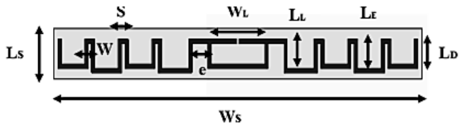
The impact of each geometric parameter on antenna performance was evaluated through parametric simulations. Increasing the meander-line length ( ) lowers the resonance frequency, while the spacing (S) and extension (e) ensure proper impedance matching with the RFID chip. A rectangular loop structure is employed for its compact size and compatibility with RFID chip assembly. By optimizing the loop structure ,including width, length, and spacing, the antenna achieves resonance at the target frequency of 868 MHz, efficient impedance matching, extended read range, stable radiation, reduced sensitivity to nearby materials, and reliable manufacturability, making it a versatile and high-performance solution for compact RFID tags.
5. Analysis of Electromagnetic Simulation Results and Interpretation
Electromagnetic validation of the proposed structure was conducted to obtain reliable simulation parameters, ensuring accurate prototype testing while preserving the environmental conditions of the RFID tag. As shown in Figure 4, the reflection coefficient reaches dB at 868 MHz, with a bandwidth of 38 MHz, indicating representative performance.
Figure 5 shows the simulated voltage standing wave ratio versus frequency. The proposed tag achieves a VSWR of 1.67 at 868 MHz, which implies that only approximately 6% of the RFID chip power is reflected back from the antenna, ensuring efficient power transfer. The simulated tag antenna exhibits an input impedance :
which is close to the complex conjugate of the RFID chip impedance at 868 MHz, as illustrated in Figure 6
6. Fabrication, Assembly, and Read-Range Testing of the Proposed Tag
The proposed RFID tag was fabricated on a textile substrate using an inkjet-printing-based prototyping approach. The conductive patterns were deposited using a Voltera printer, which enables precise, controlled, and repeatable deposition of conductive inks onto flexible substrates. This fabrication technique is particularly suitable for the development of textile-integrated RFID antennas because it supports rapid prototyping, reduces material consumption, and facilitates the implementation of complex antenna geometries while maintaining the flexibility of the textile substrate. Furthermore, the printing process offers a practical and cost-effective alternative to conventional fabrication techniques for evaluating antenna designs prior to large-scale manufacturing.
The simulation results were used to verify the antenna’s design parameters and assess its operating characteristics at the target frequency of 868 MHz. Following this validation, the antenna geometry was transferred to the textile substrate and printed using the Voltera system. Particular attention was paid to the accurate reproduction of the radiating elements and matching structure to ensure consistency between the simulated design and the fabricated prototype. The first printed prototype is presented in Figure 10, illustrating the implementation of the proposed antenna geometry on the flexible textile material.
After printing, the RFID integrated circuit was mounted onto the antenna using a conductive adhesive to establish the electrical connection between the chip and the antenna terminals. The assembly was subsequently cured at 185 ∘C for 15 minutes, following the adopted assembly procedure [13,14,15,16]. This step was essential to obtain a stable electrical interface between the chip and the printed conductive structure. Once the curing process was completed, the prototype was inspected to verify the assembly and ensure that the antenna and chip were properly integrated before proceeding to the experimental characterization.
The experimental evaluation focused on determining the read range of the fabricated RFID tag under the test conditions. Measurements were performed using an F5860-H RFID reader connected to external antennas with a gain of 12 dBi. An RSSI monitoring system was employed to record the received signal strength and assess the communication performance between the reader and the passive tag. During the measurements, the reader–tag separation was progressively adjusted to determine the maximum distance at which the tag could be reliably detected. The experimental setup and the corresponding measurement results are presented in Figure 11.
The fabricated RFID tag achieved a maximum read range of approximately 4 m, with a corresponding received signal strength indicator (RSSI) of dBm, as shown in Figure 11. The specifications of the reader used in the measurements are summarized in Table 3. This result demonstrates that the proposed textile-based antenna enables passive UHF RFID communication over a practical distance under the specified experimental conditions. The measured performance provides an experimental assessment of the fabricated prototype and complements the electromagnetic simulation results obtained using CST Microwave Studio. These measurements support the feasibility of the proposed fabrication approach for textile-integrated RFID applications. Nevertheless, the measured read range should be interpreted in relation to the reader configuration, external antenna gain, measurement environment, and tag orientation, as these parameters can influence the overall RFID link performance.
7. Conclusion
A compact and flexible UHF RFID textile tag antenna has been presented in this paper. By combining a meandered-line structure with a loop antenna, the proposed design achieves significant miniaturization while preserving efficient impedance matching to the RFID chip. The meandered-line section reduces the overall footprint by lengthening the current path within a limited area, while the loop provides inductive coupling that conjugate-matches the chip’s capacitive impedance without requiring an additional matching network. Together, these features yield robust electromagnetic performance, with stable gain and read range in the [865–868 MHz / 902–928 MHz] band.
The simulation results obtained with CST Microwave Studio were confirmed by experimental read range measurements on fabricated prototypes, showing good agreement between the simulated and measured values. The antenna also remained stable under bending, stretching, and twisting tests, which is essential for wearable use, where the fabric is constantly deformed and the human body detunes conventional tags. Moreover, the tag is washable, which makes it suitable for repeated use in textile-based personal protective equipment (PPE).
References
- López-Soriano, S.; Parrón, J. Wearable RFID Tag Antenna for Healthcare Applications. In Proceedings of the IEEE-APS Topical Conference on Antennas and Propagation in Wireless Communications (APWC); 2015; pp 287–290. [CrossRef]
- Wang, D.; Zhang, Y. J.; Tong, M. S. A Wearable UHF RFID Tag Antenna with Archimedean Spiral Strips. In Proceedings of the Progress in Electromagnetics Research Symposium–Fall (PIERS); 2017; pp 1849–1852. [CrossRef]
- El Ahmar, L.; Errkik, A.; Zbitou, J.; Bouzida, I.; Oukaira, A.; Lakhssassi, A. Novel Printed Passive Ultra High Frequency Radio Frequency Identification Antenna Using Meander Technique. Indones. J. Electr. Eng. Comput. Sci. 2024, 33, 1474–1485. [CrossRef]
- Elahmar, L.; Errkik, A.; Zbitou, J.; Bouzida, I.; Lakhssassi, A.; Latrach, M. A New Flexible Passive UHF RFID Tag Antenna Using Meander Line. AIP Conf. Proc. 2023, 2770, 070002. [CrossRef]
- Sasaki, T.; Cho, K.; Ihara, T.; Yoshihara, T. Operation Mechanism of Reflector Backed Dipole Antenna with Loop Shaped Parasitic Elements. In Proceedings of the International Workshop on Antenna Technology (iWAT); 2015; pp 113–116. [CrossRef]
- Chalasani, S. R.; Lanka, M. D.; Boppana, S. L. Design and Analysis of Loop Antenna for Wideband Operations. In Proceedings of the International Conference on Smart Systems and Inventive Technology (ICSSIT); 2022; pp 488–490. [CrossRef]
- Millen, E. A Comparison of Loop Antennas. In Proceedings of the IEEE International Symposium on Electromagnetic Compatibility; 1990; pp 451–455. [CrossRef]
- Waris, B.; Ukkonen, L.; Virkki, J.; Bjorninen, T. Wearable Passive UHF RFID Tag Based on a Split Ring Antenna. In Proceedings of the IEEE Radio and Wireless Symposium (RWS); 2017; pp 55–58. [CrossRef]
- Casula, G. A.; Montisci, G.; Rogier, H. A Wearable Textile RFID Tag Based on an Eighth-Mode Substrate Integrated Waveguide Cavity. IEEE Access 2020, 8, 11116–11123. [CrossRef]
- Kuang, S.; Ma, S.; Ukkonen, L.; Virkki, J.; Bjorninen, T. Circularly Polarized Textile Tag Antenna for Wearable Passive UHF RFID Systems. In Proceedings of the International Applied Computational Electromagnetics Society Symposium (ACES); 2018; pp 1–2. [CrossRef]
- López-Soriano, S.; Melià-Seguí, J.; Parrón, J. A Durable and Flexible, Low-Cost Tag Antenna Design for UHF RFID Wearable Applications. In Proceedings of the IEEE International Conference on RFID Technology and Applications (RFID-TA); 2023; pp 9–12. [CrossRef]
- Sharif, A.; Ouyang, J.; Raza, A.; Imran, M. A.; Abbasi, Q. H. Inkjet-Printed UHF RFID Tag Based System for Salinity and Sugar Detection. Microw. Opt. Technol. Lett. 2019, 61, 2161–2168. [CrossRef]
- Guo, H.; Yue, W.; Guo, X. Research on the Fabric-Wearable RFID Based on Inkjet Printing Technology. In Proceedings of the IEEE International Conference on Power Electronics and Computer Applications (ICPECA); 2021; pp 845–848. [CrossRef]
- Oyeka, D. O.; Batchelor, J. C.; Ziai, A. M.; Wheeler, J.; Yeates, S. Tag Diversity of Inkjet Printed Body-Worn Radio Frequency Identification Integrated Medical Sticking Plasters for Wireless Monitoring. Healthc. Technol. Lett. 2016, 3, 257–262. [CrossRef]
- Alonso-Gonzalez, L.; Ver-Hoeye, S.; Vazquez-Antuna, C.; Fernandez-Garcia, M.; Las-Heras Andres, F. Multifunctional Fully Textile-Integrated RFID Tag to Revolutionize the Internet of Things in Clothing. IEEE Antennas Propag. Mag. 2019, 61, 104–110. [CrossRef]
- Nikitin, P.; Kim, J.; Berzagui, G.; Roehe, J. M.; Rao, K. Equivalent Circuit Analysis of RFID Tags with Open Dipole Antennas. In Proceedings of the IEEE International Symposium on Antennas and Propagation and North American Radio Science Meeting; 2025; pp 2610–2613. [CrossRef]
- Sahel, Z.; Habibi, S.; Bendali, A. Design and Performance Evaluation of a High-Efficiency Circular Microstrip Patch Antenna for RFID Applications at 900 MHz. Bull. Electr. Eng. Inform. 2025, 14, 2438–2446.
Figure 1.
Conceptual diagram of the proposed RFID system using a printed wearable RFID tag integrated into personal protective equipment clothing.
Figure 1.
Conceptual diagram of the proposed RFID system using a printed wearable RFID tag integrated into personal protective equipment clothing.
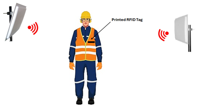
Figure 2.
Geometrical structures of (a) the meander-line structure and (b) the rectangular-loop structure.
Figure 2.
Geometrical structures of (a) the meander-line structure and (b) the rectangular-loop structure.
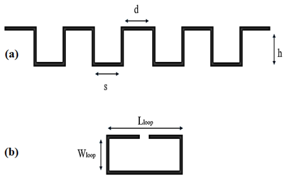
Figure 4.
Simulated reflection coefficient of the proposed RFID tag antenna as a function of frequency.
Figure 4.
Simulated reflection coefficient of the proposed RFID tag antenna as a function of frequency.
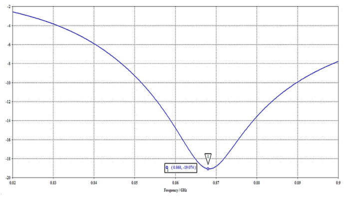
Figure 5.
Simulated VSWR of the proposed RFID tag antenna as a function of frequency.
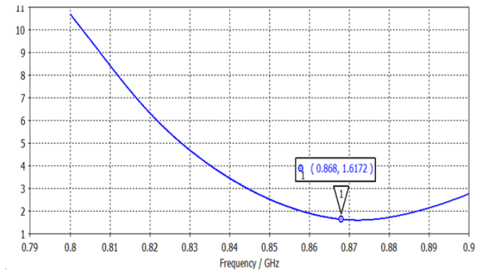
Figure 6.
Simulated input impedance of the proposed RFID tag antenna.
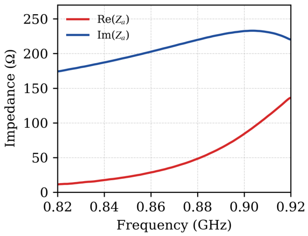
Figure 7.
Simulated gain of the proposed RFID tag antenna at 868 MHz.
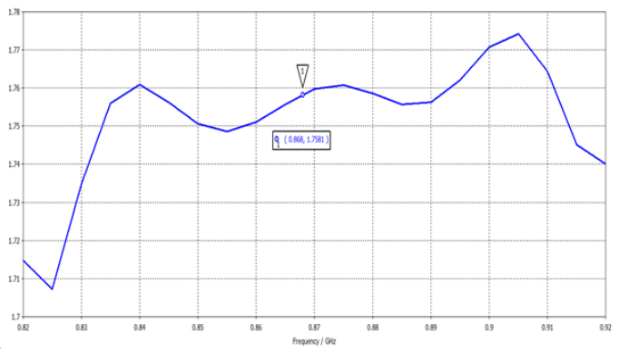
Figure 8.
Simulated directivity of the proposed RFID tag antenna at 868 MHz.
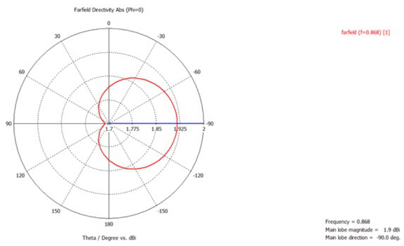
Figure 9.
Theoretical read range of the proposed RFID tag at 868 MHz.
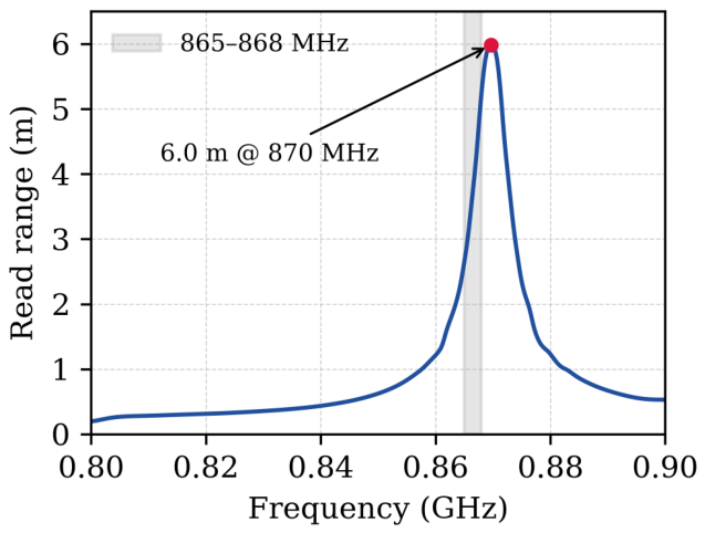
Figure 10.
Fabricated prototype of the proposed RFID tag printed on a textile substrate.
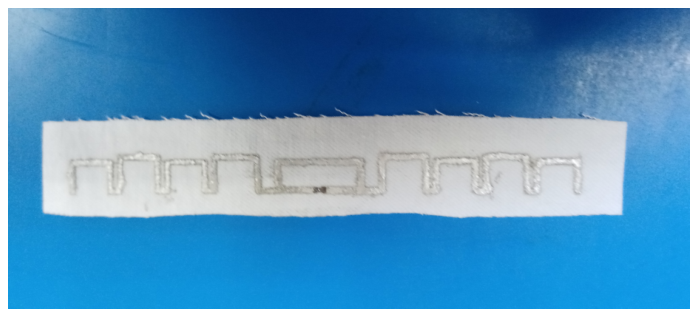
Figure 11.
Measured read range of the proposed RFID tag using an F5860-H1 reader with 12 dBi antennas.
Figure 11.
Measured read range of the proposed RFID tag using an F5860-H1 reader with 12 dBi antennas.
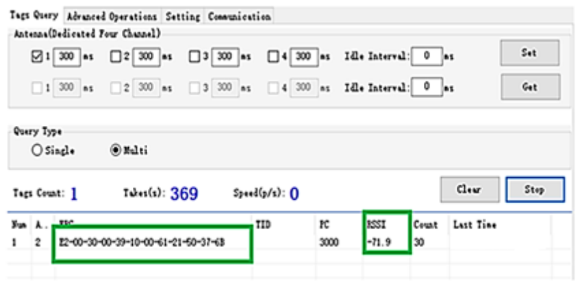
Table 1.
Dielectric and physical parameters of the materials used in this study, including the superhydrophobic textile substrate and the silver anchoring layer..
Table 1.
Dielectric and physical parameters of the materials used in this study, including the superhydrophobic textile substrate and the silver anchoring layer..
| Material | tan | H (mm) | |
|---|---|---|---|
| Superhydrophobic textile | 2.12 | 0.05 | 0.5 |
| Silver anchor | PEC | 0.05 | – |
Table 3.
Technical specifications of the F5860-H1 UHF RFID reader.
| Parameter | Specification |
|---|---|
| Frequency range | Multi-region UHF support (China, US, Europe, Korea, Japan, Taiwan) |
| Processor & design | ARM Cortex-M3 processor with an industrial-grade rugged aluminum alloy housing |
| Channels & antennas | 4 antenna ports with high-speed independent polling, power, and time configuration |
| Maximum output power | dBm |
| Receiver sensitivity | dBm |
| Read range | 0 to 28 m (depending on the 8 dBi gain antenna paired with it) |
| Recognition rate | Over 800 tags per second |
| Protocols | EPCglobal UHF Class 1 Gen 2 / ISO 18000-6C |
Disclaimer/Publisher’s Note: The statements, opinions and data contained in all publications are solely those of the individual author(s) and contributor(s) and not of MDPI and/or the editor(s). MDPI and/or the editor(s) disclaim responsibility for any injury to people or property resulting from any ideas, methods, instructions or products referred to in the content. |
© 2026 by the authors. Licensee MDPI, Basel, Switzerland. This article is an open access article distributed under the terms and conditions of the Creative Commons Attribution (CC BY) license (http://creativecommons.org/licenses/by/4.0/).
Copyright: This open access article is published under a Creative Commons CC BY 4.0 license, which permit the free download, distribution, and reuse, provided that the author and preprint are cited in any reuse.