
Submitted:
29 October 2026
Posted:
30 October 2026
You are already at the latest version
Abstract
Owing to uneven ground conditions in hilly-mountainous regions, a profiling-type shaping mechanism was adopted to follow terrain fluctuations and simultaneously complete ridge shaping. The influencing factors of ridging and profiling-type shaping were investigated, and their coupling relationship was analyzed. An EDEM–RecurDyn coupled discrete element–multibody dynamics model was established to investigate soil particle motion and ridge formation. Single-factor tests and a three-factor, three-level Box–Behnken response surface experiment were conducted using the horizontal inclination angle of the soil-covering plate, ridging blade installation angle, and blade rotational speed as factors, with the qualification rates of ridge dimensions and soil compaction as evaluation indices. As the factor levels increased, both indices initially increased and then decreased. The ridging blade installation angle had the greatest effect on ridge dimensions, whereas the soil-covering plate angle had the greatest effect on soil compaction. After rounding the multi-objective optimization results to match the practical adjustment precision of the machine, the optimal parameters were determined as a soil-covering plate angle of 25°, a ridging blade installation angle of 30°, and a rotational speed of 410 r/min. Under these conditions, the predicted qualification rates of ridge dimensions and soil compaction were 91.37% and 95.34%, respectively. Field tests using the optimal parameter combination yielded corresponding qualification rates of 88.6% and 91.4%, with relative errors of 3.0% and 4.1% compared with the predicted values. The results provide a basis for coordinated matching between soil supply and shaping compaction during potato ridging in hilly heavy clay soils.
Keywords:
potato planter
; ridging and shaping
; coordinated operation
; DEM–MBD coupling
; parameter optimization
1. Introduction
Mechanized potato planting is commonly conducted using a ridge cultivation system. Ridge height, ridge-top width, ridge-bottom width, and soil compaction jointly affect the soil-covering depth of seed potatoes, the space available for tuber expansion, and the structural stability of the ridge [1,2]. In hilly and mountainous areas, fields are small and uneven, and the soils are often heavy and poorly flowable. Terrain undulation and slope variation can cause fluctuations in machine posture and working depth, leading to unstable soil engagement and soil supply, and thus reducing ridge-forming consistency and shaping quality. Under such conditions, conventional disc- or moldboard-type ridging devices are prone to insufficient soil fragmentation, inadequate lateral soil transport, poorly formed ridges, and local collapse. Integrating seeding, ridging, and shaping into a continuous operation reduces field passes, but also makes the matching between soil supply and shaping parameters critical to ridge quality. Existing studies on ridging operations have mainly focused on soil conveying capacity, tool kinematic parameters, and structural optimization. Zhang Huan et al[3]. designed a two-stage combined ridging device for a potato planter, enabling integrated soil covering, ridging, and shaping operations. Liu Feng et al[4]. optimized the operating parameters of a rotary tillage and ridging machine based on a soil conveying model. Lü Jinqing et al[5]. analyzed the motion characteristics and soil-throwing process of rotary ridging blades for potato cultivation. These studies have provided a theoretical basis for determining the structural and operating parameters of ridging blades. However, the ridging process has generally been treated as an independent operation, with relatively limited attention paid to the coupling relationship between the amount and distribution of soil thrown by the front-end ridging component unit and the subsequent shaping component.
Ridge-shaping device mainly includes plate-type, roller-type, and combined plate–roller structures. Pei Yikun et al[6]. analyzed the relationships among pressure, sinkage, and soil compaction through soil static compression tests and discrete element simulations. Chen Xueting et al. and Bi Shiying et al[7,8]. optimized soil-compacting components from the perspectives of bionic anti-adhesion and coupled bionic design, respectively. Wang Baoai, Ma Li, and Gao Jian et al[9,10,11]. conducted the design and testing of trapezoidal ridge shapers, potato ridge-shaping and compaction devices, and hydraulic compaction and shaping devices for sweet potato production, respectively. Considerable progress has been made in the structural design and operating performance of ridge-shaping devices. Nevertheless, the shaping load is generally determined empirically or under a single operating condition, and coordinated matching with the soil supply from the preceding ridging unit remains insufficiently investigated. The discrete element method can effectively characterize soil cutting, throwing, collision, and accumulation processes [12,13], whereas multibody dynamics is well suited to analyzing the dynamic responses of spring-loaded mechanisms and shaping plates. Coupling these two approaches enables the simultaneous characterization of soil migration behavior and the mechanical response of the mechanism, thereby providing an effective means of analyzing the continuous ridging and shaping process.
In this study, a potato ridging and shaping device was designed for a potato planter based on the agronomic requirements of a single-ridge double-row planting pattern. The key components of the ridging and shaping units were parametrically designed and analyzed. On this basis, an EDEM–Recur Dyn coupled model was established to investigate the complete operating process from soil cutting and throwing to compaction and ridge shaping. The ridging blade installation angle, ridging blade rotational speed, and horizontal inclination angle of the soil-covering plate were selected as coordinated operating factors, while the qualification rates of ridge dimensions and soil compaction were used as evaluation indices. A quadratic regression experiment and multi-objective optimization were subsequently conducted to determine suitable parameter combinations, providing a reference for parameter matching of potato ridging and shaping devices under heavy clay soil conditions in hilly areas.
2. Materials and Methods
2.1. Agronomic Pattern of Potato Ridge Cultivation
Potato cultivation generally adopts two agronomic patterns: single-ridge double-row planting and single-ridge single-row planting. In this study, the single-ridge double-row planting pattern was selected as the research object. The corresponding agronomic configuration is shown in Figure 1. The ridge is generally required to have a height of 20–30 cm, a ridge-top width of no less than 40 cm, a ridge-bottom width of no less than 70 cm, and a ridge spacing of 100 cm. A relatively ridge top width and an appropriate ridge height can help maintain a favorable thermal environment during potato growth, reduce the risk of tuber greening caused by insufficient soil cover or temperature loss during the later growth stage, and thereby promote quality of commercial potato.
2.2. Overall Structure and Working Principle
The potato ridging and shaping device mainly consists of a frame, gearbox, chain transmission mechanism, left and right ridging assemblies, and a shaping component, all mounted on the frame. Power is transmitted through the gearbox and chain transmission mechanism to the ridging assemblies, driving the ridging blades to rotate and break the soil. The shaping component adjusts the angle between the covering board and the horizontal plane through a spring mechanism. On uneven terrain, the spring system adaptively regulates the compaction force during shaping, helping maintain a consistent ridge height. The overall structure is shown in Figure 2a.
The core structures include the ridging blade, blade holder, blade shaft, mounting sleeve, spring fixing tube, Springs 1 and 2, covering board, and auxiliary covering board, as shown in Figure 2b. The ridging component consists of the left and right ridging assemblies, each including the ridging blades, blade holders, blade shaft, and mounting sleeves. The ridging blades are fixed to the blade holders at a specified installation angle, and multiple mounting holes allow adjustment of blade position. The shaping component consists of the spring fixing tube, Springs 1 and 2, the covering board, and two auxiliary covering boards. Multiple pin holes along the spring fixing tube are used to adjust spring compression.
During ridging operation, the blade shafts of the left and right ridging assemblies rotate synchronously, with each shaft driving three ridging blades at high speed. The rotating blades penetrate and cut the soil, breaking large clods into smaller particles. The soil particles are then carried and thrown toward the central region between the two ridging assemblies, where an initial ridge is formed for subsequent shaping. The working process is shown in Figure 2c.
The initially formed ridge then enters the shaping component. The covering board compacts and levels excess soil on the ridge top, whereas the auxiliary covering boards compact loose soil on the inclined sides to improve ridge stability and reduce ridge collapse. The spring fixing tube is divided into upper and lower spring telescopic sections. To simplify adjustment of the shaping plate height, Spring 1 is used as the primary adjustment element. For different target ridge heights, the initial length of the telescopic section associated with Spring 1 is set accordingly before operation. During operation, the spring system adaptively regulates the shaping pressure according to surface undulations, thereby shaping and compacting the ridge. This process is shown in Figure 2d.
2.3. Ridging Component
2.3.1. Analysis of the Installation Angle Range of the Ridging Blades
As shown in Figure 2, the left and right ridging assemblies are symmetrically arranged. During operation, the ridging blades on both sides throw the soil within their respective rotational regions toward the central area, as illustrated in Figure 3 The installation angle of the ridging blade determines its soil-entry condition. To ensure effective soil penetration, the installation angle should not be excessively large. An overly large installation angle increases the soil-entry angle of the blade and enlarges the transverse contact area between the blade and the soil, thereby increasing the power consumption of the machine. In addition, an excessive installation angle reduces the spacing between the left and right ridging assemblies, which may result in an insufficient ridge-bottom width and adversely affect the ridging performance.
An excessively small installation angle would increase the spacing between the left and right ridging blades, If the installation angle is too small, the minimum spacing between the left and right ridging blades will be greater than the required ridge-bottom width for potato cultivation, which does not meet the agronomic requirements. Therefore, the following relationship can be established:
where A is the distance between the outermost ends of the left and right ridging blades, B is the maximum ridge-bottom width, C is the minimum ridge-bottom width, and θ is the installation angle of the ridging blade.L1 is Linear length of the ridging blade.
According to the structural parameters of the machine, the distance between the outermost ends of the left and right ridging blades A is 87.5 cm. Considering soil backflow characteristics, the maximum and minimum ridge-bottom widths, B and C, are taken as 65 cm and 55 cm, respectively, and the linear length L1 of the ridging blade is 28 cm. According to Eq. (1), the installation angle θ is calculated to range from 23.57° to 35.5°. For convenience in subsequent calculations, the range is simplified to 24°–36°.
2.3.2. Dynamic Analysis of the Ridging Process
The ridging blade cuts into the soil, lifts the soil, and throws it outward. This process is essential for ridge formation. Therefore, the soil motion during ridging was analyzed dynamically. As shown in Figure 4, a Cartesian coordinate system was established. The blade-shaft center was defined as the origin O. The machine forward direction was defined as the x-axis, the blade-shaft direction as the y-axis, and the vertically upward direction as the z-axis.
After the ridging blade penetrates the soil, the motion of soil particles can be divided into two main stages: the soil-particle motion consists of a lifting stage and a sliding stage. During the lifting stage, friction carries the particles upward with the blade, and the particles move in a circular path under centripetal force. After a certain period, the particles enter the sliding stage. As the particle velocity increases beyond that of the rotating ridging blade, relative sliding occurs between the soil particles and the blade surface. After sliding over a certain distance, the particles detach from the ridging blade.
According to Figure 4, the force relationship can be expressed as:
where FN is the normal force acting on the soil particle, N; f is the friction force acting on the soil particle, N; m is the mass of the soil particle, kg; ω is the angular velocity of the ridging blade, rad/s; r is the rotational radius of the ridging blade, mm; and μ is the friction coefficient.
The angular velocity of the ridging blade can be expressed in terms of the rotational speed as:
Substituting Eq. (3) into Eq. (2) gives:
It can be seen from the Eq (4) that the friction force acting on the soil particles is mainly related to the installation angle and rotational speed of the ridging blade. As the blade rotation angle increases, the centrifugal inertial force, gravitational component, and inertial effect acting on the soil particles gradually increase, whereas the normal constraint and friction exerted by the blade surface on the particles become relatively weaker. When the resultant force along the blade surface exceeds the maximum static friction force between the soil and the blade surface, the soil particles begin to slide relative to the blade. The particles are subsequently ejected when they reach the blade tip or when the normal constraint becomes insufficient. According to the work–energy theorem, the following relationship can be obtained for the entire process:
where ΔE is soil kinetic energy increment, J; E1 is the kinetic energy of soil particles at blade exit, J; E0 is the initial kinetic energy of soil particles, J; Δh is the relative height difference of the soil particle with respect to the soil surface, mm; and L is the sliding distance of the soil particle along the ridging blade, mm.
ΔE = E1 − E0 = fL − mgΔh
Substituting Eqs. (3) and (4) into Eq. (5) yields:
During actual operation, the height difference ∆h of the soil particles above the ground and the sliding distance L along the blade surface can be regarded as approximately constant. Therefore, the kinetic energy E1 of the soil particles leaving the ridging blade is mainly affected by the blade installation angle θ and rotational speed n. According to the law of conservation of energy, friction between the blade and soil provides energy for particle motion. Within an appropriate range, increasing θ enhances the tangential driving component and reduces the normal constraint, facilitating particle sliding and increasing the throwing velocity. However, an excessively large θ may intensify soil disturbance and alter particle trajectories. Increasing n enhances the centrifugal inertial force, thereby changing the normal force and friction between the soil particles and blade surface and ultimately affecting their sliding and throwing velocities.
Therefore, kinetic energy E1 of the soil particles is jointly determined by the rotational speed and installation angle of the ridging blade. Taking the initial kinetic energy E0 of the soil particles as 0 and substituting it into Eq. (6), the kinetic energy E1 of the soil particles when leaving the ridging blade can be obtained as:
2.4. Shaping Component
2.4.1. Analysis of the Horizontal Angle of the Soil-Covering Plate
Taking the ridge-height range of the single-ridge double-row planting pattern as an example, the limiting positions of the soil-covering plate in the shaping device are shown in Figure 5. The vertical distance from the center O2 of the spring sleeve to the rotational center O1 of the soil-covering plate is defined as H, and the vertical distance from the hinge point O3 of the soil-covering plate to its rotational center O1 is defined as h. The horizontal distance from the center O2 of the spring sleeve to the rotational center O1 of the soil-covering plate is denoted by d, while the horizontal distance from the hinge point O3 of the soil-covering plate to its rotational center O1 is denoted by D. The distance between the hinge point O3 and the rotational center O1 of the soil-covering plate is defined as Ln, and the distance between the hinge point O3 and the rear end of the soil-covering plate is defined as Lm.
Accordingly, the vertical distance h1 from the spring sleeve’s center O2 to the hinge point O3 of the soil-covering plate and the horizontal distance d1 from the hinge point O3 to the rotational center O2 of the soil-covering plate can be expressed as:
Therefore, the working length L1 of spring 1 can be obtained as:
Combining Eqs. (8) – (10) yields:
Let the total working length of springs 1 and 2 be Ls. The working length L2 of spring 2 can then be expressed as:
L2 = Ls − L1
During operation of the shaping device, the working lengths of springs 1 and 2 always vary correspondingly. Specifically, spring 2 extends when spring 1 contracts, and vice versa. If the ratio of the working length L1 of spring 1 to the working length L2 of spring 2 is defined as i, namely the spring-length ratio, then i can be obtained from Eqs. (11) and (12) as:
The parameter i describes the relative working lengths of the two springs. When i<1(L1< L2), indicating that Spring 1 has a shorter working length. When i>1, Spring 2 has a shorter working length. When i=1, the two springs have equal working lengths.
Based on the structural dimensions, the initial lengths of Springs 1 and 2 were both L0 = 12 cm. According to Equation (13), the relationships between the working lengths L₁ and L2 and the horizontal inclination angle α of the soil-covering plate under different total working lengths Ls were calculated, as shown in Figure 6. The black curve represents the variation in L1 with α, while the red, blue, green, and purple curves represent the variations in L2 with α at Ls = 16, 18, 20, and 22 cm, respectively.
As α increases, L1 gradually increases, whereas L2 gradually decreases. At the intersection Q, L1 = L2 = Ls/2, indicating equal compression of the two springs. As Ls increases from 16 to 22 cm, the L2 curve shifts upward and Q moves toward a larger α, indicating that the soil-covering plate angle corresponding to equal spring compression gradually increases.
At Ls values of 16 and 18 cm , the soil-covering plate was positioned relatively high, resulting in insufficient contact and compaction of the ridge. When Ls increases to 20 cm, , the initial plate position becomes more appropriate, while Springs 1 and 2 maintain suitable preload and sufficient compression space for elastic adjustment during ridge shaping. When Ls is further increased to 22 cm , the plate moves excessively downward and the initial working lengths of both springs approach their original lengths, reducing preload and limiting the available adjustment range. In particular, once Spring 2 approaches its original length, its effective elastic restraint is weakened.
Meanwhile, the excessively low plate position may cause over-compaction of the ridge, resulting in reduced ridge height and excessive soil compactness. Therefore, considering the plate position, spring preload, deformation capacity, and ridge-shaping performance, Ls =20 cm was selected as the appropriate total working length. When Ls = 20 cm, the theoretical limit range of the horizontal inclination angle α of the soil-covering plate is 5°–45°. To prevent the springs from approaching their original lengths and to maintain sufficient preload, α was set to 10°–40° for the subsequent analysis.
2.4.2. Force Analysis of the Spring Fixing Tube
The shaping device mainly relies on the combined action of springs 1 and 2 to generate the compaction force. After the two springs are compressed, part of the spring force is transmitted to the fixed spring sleeve and is balanced by the corresponding support reaction. Therefore, this force component does not affect the force balance of the soil-covering plate and is not considered in the analysis. The remaining force components generate elastic forces on the upper and lower sides of the spring fixing tube, respectively. Their resultant force acts at the hinge point of the soil-covering plate, maintaining the plate in static equilibrium while retaining part of the compaction force to level the ridge top. The force analysis of the soil-covering plate under this condition is shown in Figure 7.
As shown in Figure 7, during ridge compaction by the shaping device, the two springs deform in opposite directions under the action of soil resistance. Spring 1 is compressed from its working length L1 by an amount ΔL, whereas spring 2 is extended from its working length L2 by the same amount ΔL. According to the deformation relationship between the two springs, the following equation can be obtained:
Combining Eqs. (11) and (12) gives:
The above equation shows that the force Fg exerted by the spring fixing tube at the hinge point of the soil-covering plate is affected by Ls, H, Ln, d, and α. Among these parameters, H, Ln, and d are determined by the structural dimensions, while Ls was determined above to be 20 cm. Therefore, during actual operation, the magnitude of Fg is mainly related to the angle α between the soil-covering plate and the horizontal plane. Figure 7 further shows that, when the soil-covering plate contacts the soil, the soil resistance f, the weight G of the plate, and the force Fg exerted by the spring fixing tube satisfy the following relationship about the rotation center O1 of the soil-covering plate:
FgLncosβ + GLgsinα − fLf = 0
Equation (16) further indicates that, during operation of the shaping device, Fg dynamically adjusts in response to changes in the soil resistance f. When the amount of soil entering the shaping device increases, the soil resistance increases accordingly. Under the action of the soil, the soil-covering plate rotates upward about the hinge point O1, thereby decreasing its angle α relative to the horizontal plane. This rotation causes corresponding changes in the spring deformation and Fg, allowing moment equilibrium to be restored. To ensure satisfactory ridge-forming quality, Fg should remain within a reasonable range. If Fg is excessively large, the compaction force exerted by the soil-covering plate will be too high, easily resulting in excessive ridge compaction and insufficient ridge height. If Fg is too small, the shaping constraint will be insufficient, making it difficult for the ridge-top width and profile dimensions to satisfy agronomic requirements.
2.5. Simulation Tests of Ridging and Shaping Interaction
2.5.1. Establishment of the Discrete-Element and Multibody-Dynamics Models
The predominant soil type in the hilly regions of southwestern China is loam. To visualize the coordinated operation of the ridging and shaping devices and accurately simulate soil–implement interactions, the Hertz–Mindlin with JKR contact model was adopted for soil particles [14,15,16,17]. The ridging and shaping device models were loaded into Solidworks2023. In EDEM2020, the soil-particle radius was set to 5 mm, and the soil-bin dimensions were set to 1,200 × 1,200 × 250 mm. The soil bin was then filled with particles. The soil density, Poisson’s ratio, and shear modulus were set to 2.09 × 10³ kg·m⁻³, 0.38, and 1 × 10⁶ Pa, respectively. The soil-soil and soil-ridging-blade contact parameters were selected with reference to the relevant literature, as listed in Table 1 [18,19,20,21,22]. After the preliminary models of the ridging and shaping devices were established in Solidworks2023, they were appropriately simplified by removing bolts and other accessories. The simplified models were saved in STEP format and subsequently imported into RecurDyn2020 for preprocessing. The model parameters and coordinate system in Recur Dyn were kept consistent with those in EDEM.
2.5.2. Coupled Simulation Analysis
The model preprocessed in Recur Dyn was imported into EDEM. The principle of discrete-element-method and multibody-dynamics (DEM–MBD) coupling[23,24] is illustrated in Figure 8, and the coordinated ridging and shaping process is shown in Figure 9. At the initial simulation stage (1.58 s), the ridging blades penetrated the soil and completed soil fragmen tation, disturbance, and throwing, gradually forming the initial ridge. As the implement advanced (2.38 s), soil continuously accumulated toward the center, and the soil-covering plates began levelling and compacting the loose soil. By 3.18 s, soil supply from the front ridging device was essentially complete. The rear shaping device continued to constrain the ridge profile, producing a progressively flatter ridge top. These results showed that the ridging and shaping devices formed a continuous and coordinated soil-supply and shaping process. The intermediate levels of the three factors, including the ridging-blade rotational speed, installation angle, and soil-covering plate horizontal inclination angle, were set to 400 r/min, 30°, and 25°, respectively, for the coupled simulation.
Coupled simulations were conducted at intermediate factor levels to investigate soil–blade interaction and shaping characteristics. The ridging-blade mounting angle and initial soil-covering plate angle were set to 24° and 25°, respectively, with a forward speed of 0.5 m/s and blade rotational speeds of 350, 400, and 450 r/min [25]. As shown in Figure 10(a–c), blue regions represent soil particles. The left and right ridging blades cut and disturb the soil, transporting particles toward the ridge center to form the initial ridge. High-energy particles were concentrated near the ridging blades, and the maximum particle kinetic energies were 2.21, 2.70, and 3.97 J, respectively. Neglecting air resistance, increased kinetic energy indicates higher particle velocity after leaving the blades. In addition, the initial soil-covering plate angle was set to 25°, the forward speed to 0.5 m/s, and the ridging-blade rotational speed to 400 r/min. The ridging-blade mounting angles were set to 24°, 30°, and 36°, as shown in Figure 10(d–f). At 24°, although soil was thrown toward the center by the left and right ridging assemblies, a large void remained in the central ridge region. As the mounting angle increased to 30° and 36°, soil accumulation increased markedly and the throwing range expanded. Some particles were thrown onto the frame above the ridge, particularly at 36°. The maximum soil-particle kinetic energies at 24°, 30°, and 36° were 2.70, 2.97, and 3.15 J, respectively, increasing with mounting angle. However, this increase was less pronounced than that caused by rotational speed. Therefore, larger rotational speeds and mounting angles favored soil throwing, while their effects on ridge dimensions and soil compaction required further field verification.
3. Results and Discussion
3.1. Evaluation Indices
Based on these results, the factors with significant effects on soil-throwing and ridging, as well as those influencing ridge shaping, were selected. Field experiments were then conducted to evaluate the coordinated operation of the soil-throwing ridging and ridge-shaping devices. Soil compaction affects potato growth and development. Previous studies have shown that potato root growth is not adversely affected when soil compaction does not exceed 0.98 MPa [26]. Therefore, 0.98 MPa was used as the upper limit for acceptable soil compaction. Ridge quality is primarily evaluated using the ridge-dimension qualification rate. Accordingly, the soil-compaction and ridge-dimension qualification rates were defined as follows [27,28,29,30]:
where Y1 is the ridge-dimension qualification rate, %; Gh is the number of qualified ridge-dimension measurements; Gz is the total number of ridge-dimension measurements; Y2 is the soil-compaction qualification rate, %; Ne is the number of qualified soil-compaction measurements; and Nc is the total number of soil-compaction measurements.
3.1.1. Results and Analysis of the Single-Factor Experiments
Single-factor experiments were conducted to determine reasonable ranges for the main operating parameters of the ridging and shaping device. The horizontal angle α of the soil-covering plates, ridging-blade mounting angle θ, and ridging-blade rotational speed n were selected as the experimental factors. During each experiment, only the factor under investigation was varied, while all other parameters remained constant. Based on the structural analysis above, the ridging-blade installation angle was set to 24°–36°. Considering the operating range of the prototype and the requirements for soil throwing and ridge shaping, the ridging-blade rotational speed and the horizontal inclination angle of the soil-covering plate were set to 350–450 r/min and 10°–40°, respectively. Accordingly, five levels were selected for each factor, as shown in Table 2, and the corresponding results are shown in Figure 11.
As shown in Figure 11a, the qualification rate of ridge dimensions initially increased and then decreased with increasing horizontal inclination angle of the soil-covering plate. When the angle increased from 10° to 25°, the shaping effect on the ridge gradually improved, and the qualification rate reached a relatively high level at 25°. However, a further increase in the angle intensified soil pushing and local accumulation, resulting in a decline in ridge dimensional stability. As shown in Figure 11b, the qualification rate increased as the ridging-blade mounting angle increased from 24° to 27°. This was mainly because the larger mounting angle enhanced soil transport toward the central ridge region and promoted the formation of a fuller ridge. When the mounting an angle exceeded 27°, the soil-throwing range and disturbance increased, it may create a large dimensional ridge causing low qualification rate. As shown in Figure 11c, increasing the ridging-blade rotational speed from 350 to 400 r/min improved soil fragmentation and throwing capacity, thereby increasing the qualification rate of ridge dimensions. When the rotational speed was further increased to 425–450 r/min, the kinetic energy and scattering of soil particles increased, which reduced the stability of ridge formation. Therefore, moderate values of the three factors were more favorable for maintaining stable and qualified ridge dimensions.Bulleted lists look like this:
As shown in Figure 12a, the soil compaction qualification rate increased as the horizontal angle of the soil-covering plate increased from 10° to 25°, reaching a relatively high level at approximately 25°. A further increase to 32.5° and 40° reduced the qualification rate, mainly because excessive soil pushing and local accumulation decreased compaction uniformity. As shown in Figure 12b, the qualification rate increased significantly as the ridging-blade mounting angle increased from 24° to 30° and reached its highest level near 30°. An appropriate mounting angle improved soil transport toward the central ridge region, providing a more uniform soil basis for subsequent compaction. However, further increases to 33° and 36° intensified soil throwing and disturbance, resulting in reduced soil distribution uniformity and compaction quality. As shown in Figure 12c, the qualification rate generally increased as the ridging-blade rotational speed increased from 350 to 425 r/min and remained relatively high at 400–425 r/min. A moderate increase in rotational speed improved soil fragmentation and transport. However, at 450 r/min, intensified soil disturbance and particle scattering caused a slight decrease in the qualification rate. Overall, moderate values of the soil-covering plate angle, ridging-blade mounting angle, and rotational speed were more favorable for achieving uniform and stable ridge compaction.
3.1.2. Results and Analysis of the Box-Behnken Design
Based on the results of the single-factor experiments, the combined effects of the soil-covering-plate horizontal angle, ridging-blade mounting angle, and ridging-blade rotational speed on ridge-forming quality were further investigated. A three-factor, three-level Box–Behnken design was employed to determine a suitable combination of operating parameters for the ridging and shaping device [31,32]. A total of 17 experimental runs were conducted, including 12 design-point runs and five replicated center-point runs. The center-point replicates were used to estimate pure experimental error and assess the lack of fit of the quadratic regression models. During the experiments, the implement forward speed, operating depth, operating distance, and other conditions were kept approximately constant. The experimental order was randomized to minimize the influence of variations in external conditions. The results of the 17 experimental runs are presented in Table 3.
Significance testing and analysis of variance were performed using Design-Expert. The quadratic regression models for the ridge-dimension qualification rate Y1 and soil-compaction qualification rate Y2 were both highly significant (P < 0.0001). The lack-of-fit P-values were 0.1962 and 0.1317, respectively, both exceeding 0.05. Thus, the lack of fit was non-significant, indicating that the models adequately described the relationships between the experimental factors and response indices. Based on the F-values of the linear terms, the factors affecting Y1 were ranked as X1 > X2 > X3. The factors affecting Y2 were ranked as X2 > X1 > X3. Quadratic regression models were established for Y1 and Y2 as follows:
3.1.3. Response Surface Analysis
Design-Expert was used to analyze the data in Table 3. The resulting response surfaces describing the interaction effects on the ridge-dimension qualification rate Y1 and soil-compaction qualification rate Y2 are shown in Figure 13.
Figure 13a shows that, at a rotational speed of 400 r/min, the ridge-dimension qualification rate generally increased and then decreased as the horizontal and mounting angles increased. At a small horizontal angle, the soil-covering plates provided insufficient restraint and shaping, resulting in poor ridge-profile stability. As the horizontal angle increased, the downward pressure and shaping action of the plates increased, thereby improving the ridge-dimension qualification rate. When the horizontal angle became excessively large, the soil was over compressed and displaced laterally. This condition readily reduced the ridge height and consequently decreased the qualification rate.
Figure 13b shows that, at a soil-covering-plate horizontal angle of 25°, the ridge-dimension qualification rate generally increased and then approached a plateau as the mounting angle and rotational speed increased. When the rotational speed increased from 350 to 400–425 r/min, soil fragmentation and transport continuity improved, resulting in more complete ridge filling. As the rotational speed increased further, soil scattering and uneven redeposition intensified, slowing the increase in the qualification rate.
Figure 13c shows a clear interaction between the soil-covering-plate horizontal angle and ridging-blade mounting angle at a rotational speed of 400 r/min. At a small horizontal angle, the soil-covering plates provided insufficient compaction and restraint, resulting in low ridge compaction. As the angle increased, the compaction effect increased and the qualification rate gradually improved. However, an excessively large angle caused localized over compaction and reduced the qualification rate. A moderate increase in mounting angle increased the soil supply and improved ridge-filling uniformity. An excessively large mounting angle, however, readily caused soil accumulation and a non-uniform compaction distribution.
Figure 13d shows that, at a mounting angle of 30°, a moderate increase in rotational speed improved soil fragmentation and transport continuity. However, an excessively high rotational speed intensified soil disturbance and uneven redeposition.
The ridge-dimension qualification rate Y1 and soil-compaction qualification rate Y2 were selected as the objective functions. The mounting angle X1, soil-covering-plate horizontal angle X2, and rotational speed X3 were selected as the independent variables. The constraints were defined as follows:
Equal weights were assigned to the two response indices. The optimized soil-covering-plate horizontal angle, mounting angle, and rotational speed were 25.29°, 30.02°, and 410.1 r/min, respectively. Under these conditions, the predicted ridge-dimension and soil-compaction qualification rates were 91.36% and 95.37%, respectively. Considering the practical adjustment precision of the device, the optimized parameters were rounded to a soil-covering-plate horizontal angle of 25°, a ridging-blade mounting angle of 30°, and a rotational speed of 410 r/min. The corresponding predicted values of the two indices were 91.37% and 95.34%, respectively.
3.2. Field Experiments
3.2.1. Experimental Conditions
The ridging and shaping experiments were conducted on 17 May 2026 at the experimental field of the Institute of Modern Agricultural Equipment, Xihua University, Chengdu, Sichuan Province, China.( 30.774°N, 103.959°E) The experimental field had heavy, compacted loam containing numerous stones. The field was first ploughed using a disc plough and then repeatedly tilled using a rotary tiller to break up the soil. The cultivated soil layer was 25 cm deep, the soil moisture content was 21.6%, and the experimental plot was 50 m long. As shown in Figure 14, a Model 504 tractor equipped with a three-point-mounted rotary tillage and ridging prototype was used. The rotary tiller was fitted with three ridging blades. The rear power take-off speed of the tractor was 540 r/min. The forward speed and rotational speed during rotary tillage and ridging were 0.5 m/s and 410 r/min, respectively. The implement operated in a single-ridge, double-row configuration.
3.2.2. Experimental Results
To verify the reliability of the response surface optimization, five independent replicate field experiments were conducted using the rounded optimal parameters. The implement forward speed was maintained at 0.5 m/s, while the operating depth and soil conditions were kept approximately consistent with those of the preceding experiments. The results are presented in Table 4. After each experimental run, the ridge height, ridge-top width, ridge-bottom width, and soil compaction were measured using the same sampling-point arrangement and evaluation method. The ridge-dimension and soil-compaction qualification rates were then calculated. The measured mean values of the two indices were 88.6% and 91.4%, respectively. Their relative errors from the model-predicted values of 91.37% and 95.34% were 3.0% and 4.1%, respectively. Both errors were within acceptable ranges. These results indicate that the regression models provided satisfactory predictive performance and that the optimized parameter combination satisfied the operational requirements for potato ridging and shaping.
4. Conclusions
(1) A potato ridging and shaping machine comprising left- and right-side soil-throwing ridging devices and a double-spring-loaded shaping device was developed. The ridging blades cut, fragmented, and threw the soil toward the center of the ridge. The soil-covering plates and auxiliary soil-covering plates then compacted and reshaped the initial ridge profile. Theoretical analysis indicated that the reasonable range of the ridging-blade mounting angle was 24° to 36°. When the total working length of the two springs was 20 cm, the horizontal angle of the soil-covering plates was adjustable from 5° to 45°. This range satisfied the adjustment requirements for different ridge heights and compaction forces.
(2) An EDEM–Recur Dyn coupling model of the ridging and shaping device was established. The model simulated the continuous processes of soil cutting, throwing, accumulation, and spring-loaded shaping. As the rotational speed increased from 350 to 450 r/min, the maximum kinetic energy of the soil particles increased from 2.21 to 3.97 J. The number of soil particles in the central ridge region also increased. When the ridging-blade mounting angle increased from 24° to 36°, the maximum soil-particle kinetic energy increased from 2.70 to 3.15 J. Both the soil-throwing range and the soil supply to the central ridge region increased accordingly. Rotational speed had a more pronounced effect on soil-particle kinetic energy than the mounting angle.
(3) The single-factor experiments showed that the ridge-dimension and soil-compaction qualification rates generally increased and then decreased as the soil-covering-plate horizontal angle, ridging-blade mounting angle, and rotational speed increased. Relatively satisfactory ridging and shaping performance was obtained near the intermediate level of each factor. Analysis of variance for the Box–Behnken experiment showed that the regression models for both qualification rates were highly significant. The lack-of-fit P-values were 0.1962 and 0.1317, respectively, both exceeding 0.05. The factors affecting the ridge-dimension qualification rate were ranked as mounting angle, soil-covering-plate horizontal angle, and rotational speed. Those affecting the soil-compaction qualification rate were ranked as soil-covering-plate horizontal angle, mounting angle, and rotational speed. The interaction between the mounting angle and soil-covering-plate horizontal angle had a highly significant effect on both indices.
(4) Multi-objective optimization was conducted to maximize the ridge-dimension and soil-compaction qualification rates simultaneously. The optimal soil-covering-plate horizontal angle, ridging-blade mounting angle, and rotational speed were 25.29°, 30.02°, and 410.10 r/min, respectively. The corresponding predicted qualification rates were 91.36% and 95.37%. Considering the practical adjustment precision of the machine, the parameters were rounded to a soil-covering-plate horizontal angle of 25°, a mounting angle of 30°, and a rotational speed of 410 r/min. The corresponding predicted qualification rates after rounding were 91.37% and 95.34%, respectively. Five field validation experiments were conducted using the rounded parameter combination. Field tests showed that the measured mean qualification rates for ridge dimensions and soil compaction were 88.60% and 91.40%, respectively. Their relative errors from the model predictions were 3.03% and 4.13%, demonstrating the satisfactory reliability of the optimization results.
Author Contributions
Conceptualization, H.Y.; methodology, H.Y.; software, H.Y.and J.L.; validation, M.L., H.Y., F.C.and J.H.; formal analysis, H.W., S.H.,and H.Y.; investigation, H.Y.and Z.P.; resources, M.L.; data curation, J.L., H.W. and H.Y.; writing—review and editing, H.Y.; visualization, H.Y.; supervision, M.L.; project administration, M.L.; funding acquisition, M.L. All authors have read and agreed to the published version of the manuscript.
Funding
Sichuan Science and Technology Program (2024ZDZX0028), Sichuan Provincial Pilot Project for Integrated Research and Development, Manufacturing, Promotion and Application of Agricultural Machinery (CNH[2024]582-2).
Institutional Review Board Statement
Not applicable.
Data Availability Statement
The datasets generated and analyzed during the current study are available from the corresponding author on reasonable request.
Acknowledgments
Conflicts of Interest
The authors declare no conflicts of interest.
References
- Kouwenhoven, J.K.; Perdok, U.D.; Jonkheer, E.C.; Sikkema, P.K.; Wieringa, A. Soil ridge geometry for green control in French fry potato production on loamy clay soils in The Netherlands. Soil Tillage Res. 2003, 74, 125–141. [Google Scholar] [CrossRef]
- Stalham, M.A.; Allen, E.J.; Rosenfeld, A.B.; Herry, F.X. Effects of soil compaction in potato (Solanum tuberosum) crops. J. Agric. Sci. 2007, 145, 295–312. [Google Scholar] [CrossRef]
- Zhang, H.; Guo, X.Y.; Zhang, J.; Yang, R.B.; Wang, W.J.; Qi, S.C. Design and experiment of two-stage combined ridging device for potato planter. Trans. Chin. Soc. Agric. Mach. 2023, 54 (Suppl. 1), 76–83, 92. (In Chinese) [Google Scholar] [CrossRef]
- Liu, F.; Yang, W.P.; Luo, J.Y. Parameter optimization design of rotary tillage and ridging machine based on soil conveying quantity model. J. Chin. Agric. Mech. 2014, 35, 21–25, 30. (In Chinese) [Google Scholar]
- Lü, J.Q.; Wang, Y.B.; Dui, H.; Li, Z.H.; Li, J.C.; Liu, Z.Y. Design of key components of driving-type potato cultivator and its soil-broken effect experiment. Trans. Chin. Soc. Agric. Mach. 2017, 48, 49–58. (In Chinese) [Google Scholar] [CrossRef]
- Pei, Y.K.; Song, Q.L.; Chen, X.T.; Xia, Y.Q.; Chen, Y.; Tang, S.M.; Ma, S.S.; Liu, X.P.; Zhang, X.L. Soil compaction test and fertilizer particle displacement analysis for layered fertilization in tobacco ridges. J. Henan Agric. Univ. 2024, 58, 654–662. (In Chinese) [Google Scholar] [CrossRef]
- Chen, X.T.; Li, H.Q.; Xue, C.Q.; Zhou, X.M.; Zhao, R.Z.; Pei, Y.K.; Zhang, X.L. Bionic design and experiment on press roller of tobacco ridge and fertilizing machine. J. Agric. Mech. Res. 2023, 45, 161–165, 171. (In Chinese) [Google Scholar] [CrossRef]
- Bi, S.Y.; Liu, W.D.; Guo, L.J. Dynamic analysis and parameter optimization of coupled bionic press roller on soybean ridge. J. Chin. Agric. Mech. 2020, 41, 25–32. (In Chinese) [Google Scholar]
- Wang, B.A.; Zhang, Q.; Sun, W. Design of a novel trapezoidal ridge shaper. J. Chin. Agric. Mech. 2016, 37, 39–41, 53. (In Chinese) [Google Scholar]
- Ma, L. Design analysis and performance test of ridge forming and pressing device for potato rotary tillage ridge planter. Agric. Mach. 2017, (No. 10), 97–100. (In Chinese) [Google Scholar]
- Gao, J.; Zhang, X.S.; Chen, X.Y. Design and experiment of sweet potato ridge shaping machine suppression and shaping device based on EDEM. Agric. Eng. 2024, 14, 95–99. (In Chinese) [Google Scholar] [CrossRef]
- Shmulevich, I. State of the art modeling of soil–tillage interaction using discrete element method. Soil Tillage Res. 2010, 111, 41–53. [Google Scholar] [CrossRef]
- Ucgul, M.; Fielke, J.M.; Saunders, C. Three-dimensional discrete element modelling of tillage: Determination of a suitable contact model and parameters for a cohesionless soil. Biosyst. Eng. 2014, 121, 105–117. [Google Scholar] [CrossRef]
- Cundall, P.A.; Strack, O.D.L. A discrete numerical model for granular assemblies. Géotechnique 1979, 29, 47–65. [Google Scholar] [CrossRef]
- Coetzee, C.J. Review: Calibration of the discrete element method. Powder Technol. 2017, 310, 104–142. [Google Scholar] [CrossRef]
- Asaf, Z.; Rubinstein, D.; Shmulevich, I. Determination of discrete element model parameters required for soil tillage. Soil Tillage Res. 2007, 92, 227–242. [Google Scholar] [CrossRef]
- Wang, J.W.; Li, X.; Gao, P.X.; Na, M.J.; Wang, Q.; Zhou, W.Q. Design and experiment of high efficiency drag reducing shovel for carrot combine harvester. Trans. Chin. Soc. Agric. Mach. 2020, 51, 93–103. (In Chinese) [Google Scholar] [CrossRef]
- Fan, Y. Research on Potato Digging Mechanism and Bionic Shovel Design Based on the Discrete Element Method. Master’s Thesis, Shenyang Agricultural University, Shenyang, China, 2020. (In Chinese) [Google Scholar]
- Du, J.; Zhang, W.L.; Zhu, Y.H.; Zhang, J.M.; Xia, J.F. Study on the characteristic of power distribution of rotary tillage by discrete element method. J. Anhui Agric. Univ. 2020, 47, 1031–1037. (In Chinese) [Google Scholar] [CrossRef]
- Pang, J.; Lin, X.J.; Chen, S.T.; et al. Study on measurement and calibration methods of soil parameters used in the discrete element method. J. Anhui Agric. Sci. 2023, 51, 6–11. (In Chinese) [Google Scholar]
- Zhang, X.Y. Experimental Study on the Action Mechanism and Parameters of Spoon-Clamp Type Garlic Precision Seeding Device. Master's Thesis, Heilongjiang Bayi Agricultural University, Daqing, China, 2022. (In Chinese) [Google Scholar]
- Ji, L.L.; Xie, H.X.; Yang, H.G.; Wei, H.; Yan, J.C.; Shen, H.Y. Simulation analysis of potato dry soil cleaning device based on EDEM–RecurDyn coupling. J. Chin. Agric. Mech. 2021, 42, 109–115. (In Chinese) [Google Scholar] [CrossRef]
- Bae, B.M.; Kim, M.S.; Choi, S.O.; Kim, Y.S.; Kim, W.S.; Kim, Y.J. Development of a power prediction model for rotary tillage in paddy loam field using DEM-MBD coupling method. Comput. Electron. Agric. 2025, 239, 111051. [Google Scholar] [CrossRef]
- Wang, Y.P.; Zhou, X.J.; Lu, X.; Liang, Y.C.; Zhang, X.W.; Wang, R.R. Effects of soil compaction on root, stolon, yield and quality of potato. J. Desert Res. 2016, 36, 1590–1596. (In Chinese) [Google Scholar] [CrossRef]
- Weng, W.X.; Chen, W.X.; Chen, L.B.; He, M.L.; Wang, J.F.; Zheng, S.H. Optimization of working parameters for rotary-cutting soil collection device: Experiment and simulation. Agriculture 2024, 14, 38. [Google Scholar] [CrossRef]
- DB23/T 2351—2019; Specification for Evaluation of Operating Quality of Ridging Machines. Heilongjiang Provincial Administration for Market Regulation: Harbin, China, 2019. (In Chinese)
- Hamza, M.A.; Anderson, W.K. Soil compaction in cropping systems: A review of the nature, causes and possible solutions. Soil Tillage Res. 2005, 82, 121–145. [Google Scholar] [CrossRef]
- Lipiec, J.; Hatano, R. Quantification of compaction effects on soil physical properties and crop growth. Geoderma 2003, 116, 107–136. [Google Scholar] [CrossRef]
- Bengough, A.G.; McKenzie, B.M.; Hallett, P.D.; Valentine, T.A. Root elongation, water stress, and mechanical impedance: A review of limiting stresses and beneficial root tip traits. J. Exp. Bot. 2011, 62, 59–68. [Google Scholar] [CrossRef] [PubMed]
- Box, G.E.P.; Behnken, D.W. Some new three level designs for the study of quantitative variables. Technometrics 1960, 2, 455–475. [Google Scholar] [CrossRef]
- Myers, R.H.; Montgomery, D.C.; Anderson-Cook, C.M. Response Surface Methodology: Process and Product Optimization Using Designed Experiments, 4th ed.; John Wiley & Sons: Hoboken, NJ, USA, 2016. [Google Scholar]
- Montgomery, D.C. Design and Analysis of Experiments, 9th ed.; John Wiley & Sons: Hoboken, NJ, USA, 2017. [Google Scholar]
Figure 1.
Ridge farming diagram.
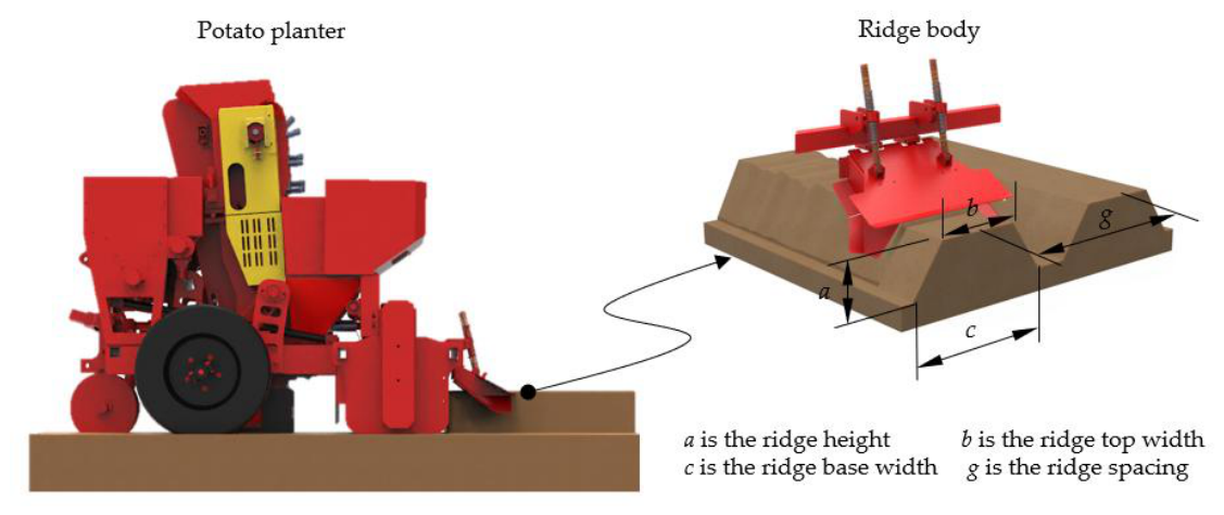
Figure 2.
Schematic diagram of the structure and working principle of the Ridge-Shaping device:1. Ridging blade,2. Blade holder, 3. Blade shaft, 4.Mounting sleeve, 5. Spring fixing tube, 6. Spring 2, 7. Spring 1, 8. Covering board, 9. Auxiliary covering board.
Figure 2.
Schematic diagram of the structure and working principle of the Ridge-Shaping device:1. Ridging blade,2. Blade holder, 3. Blade shaft, 4.Mounting sleeve, 5. Spring fixing tube, 6. Spring 2, 7. Spring 1, 8. Covering board, 9. Auxiliary covering board.
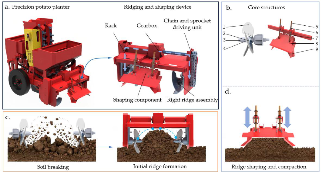
Figure 3.
Illustration of ridge plowing operation.(a) Schematic diagram of the ridging operation;(b) Working of the right ridging assembly.
Figure 3.
Illustration of ridge plowing operation.(a) Schematic diagram of the ridging operation;(b) Working of the right ridging assembly.
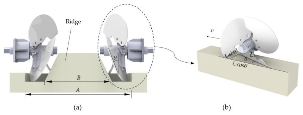
Figure 4.
Ridge plow force analysis.(a) Front view;(b) left view.
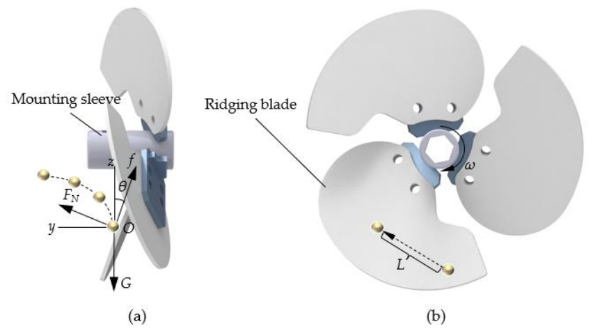
Figure 5.
Schematic of a shaping component structure.
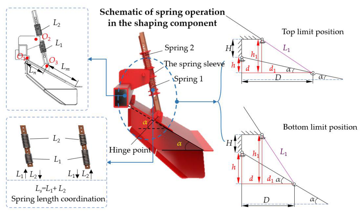
Figure 6.
Relationship between the working lengths of Spring 1, Spring 2, and the horizontal inclination angle α.
Figure 6.
Relationship between the working lengths of Spring 1, Spring 2, and the horizontal inclination angle α.
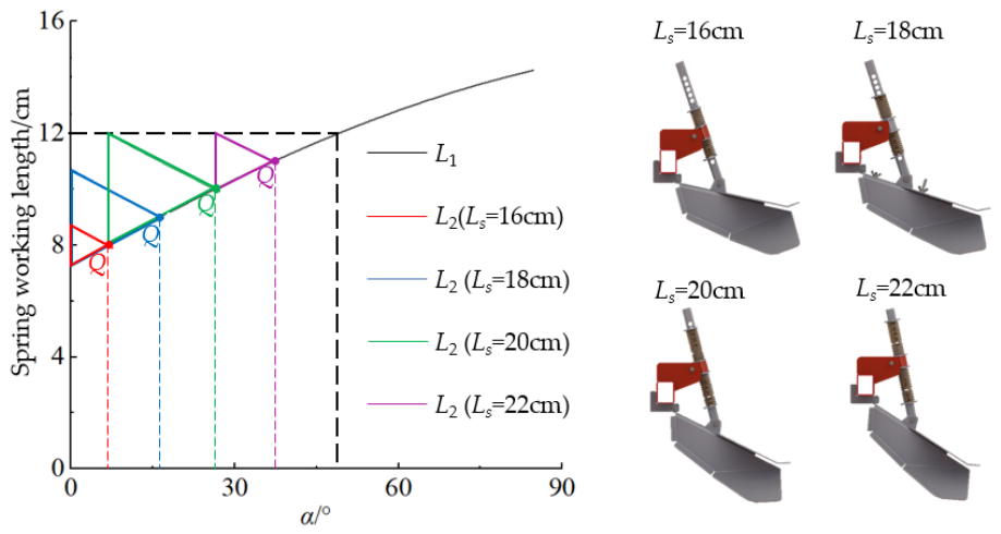
Figure 7.
Spring mounted pipe stress analysis. Note: F1 is the elastic force generated by spring 1; F2 is the elastic force generated by spring 2; Fg is the resultant force of Spring 1 and Spring 2.; Ft is the component of F2 normal to the soil-covering plate; f is the soil resistance; G is the weight of the soil-covering plate; Lf is the distance from the line of action of f to point O1; Lg is the distance from the line of action of G to point O; and β is the angle between the spring fixing tube and the soil-covering plate.
Figure 7.
Spring mounted pipe stress analysis. Note: F1 is the elastic force generated by spring 1; F2 is the elastic force generated by spring 2; Fg is the resultant force of Spring 1 and Spring 2.; Ft is the component of F2 normal to the soil-covering plate; f is the soil resistance; G is the weight of the soil-covering plate; Lf is the distance from the line of action of f to point O1; Lg is the distance from the line of action of G to point O; and β is the angle between the spring fixing tube and the soil-covering plate.
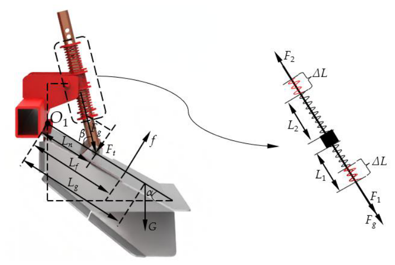
Figure 8.
DEM-MBD coupling schematic diagram.
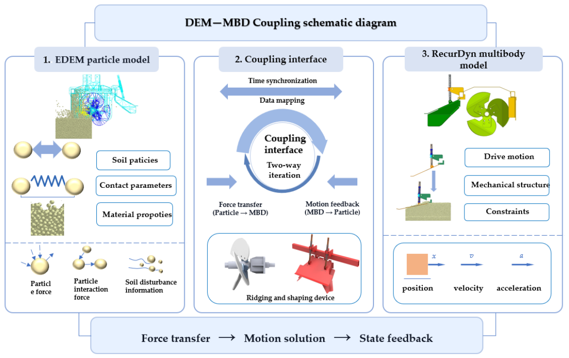
Figure 9.
Coupled ridging and shaping operation process.
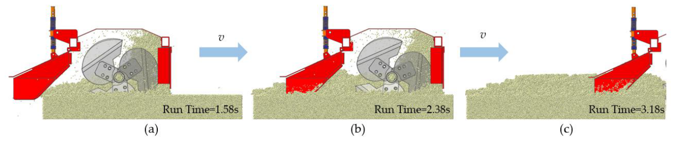
Figure 10.
Soil throwing characteristics under different operating factors.
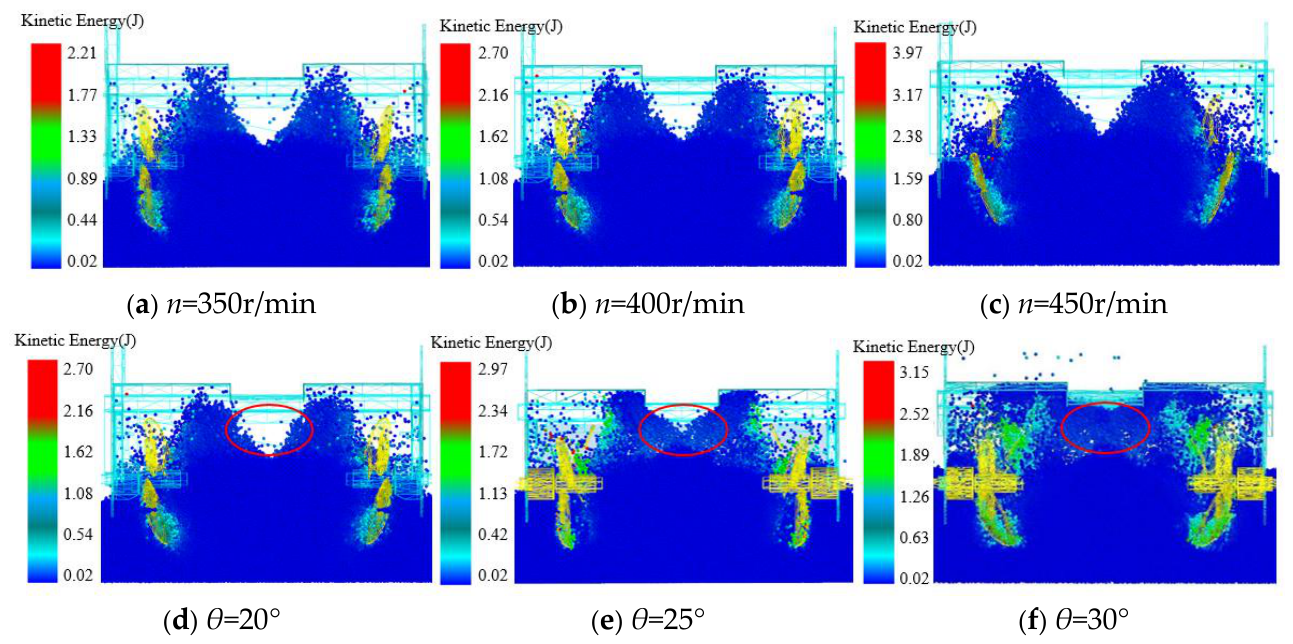
Figure 11.
Single-factor experiment results of Y1.
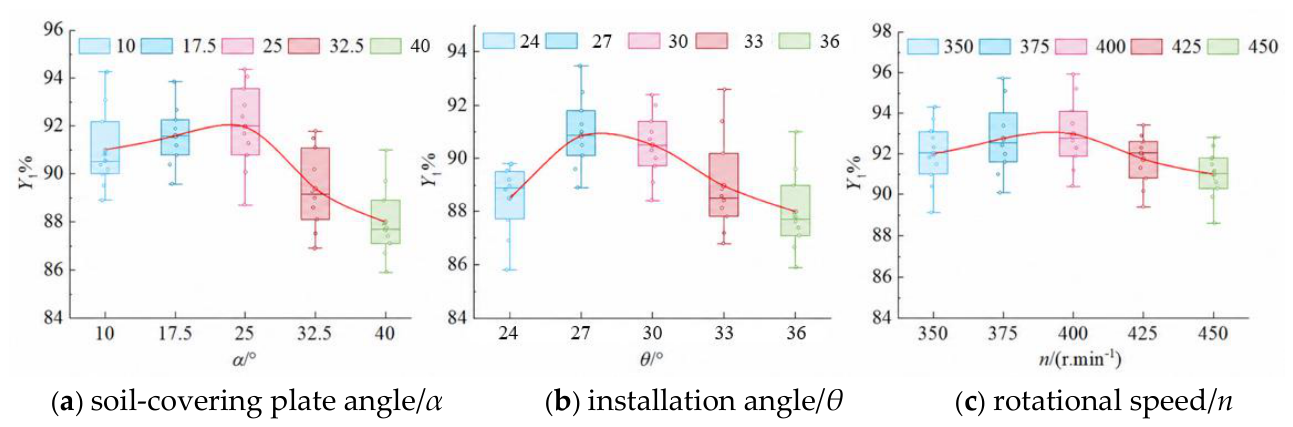
Figure 12.
Single-factor experiment results of Y2.
Figure 13.
Interaction term response surface.
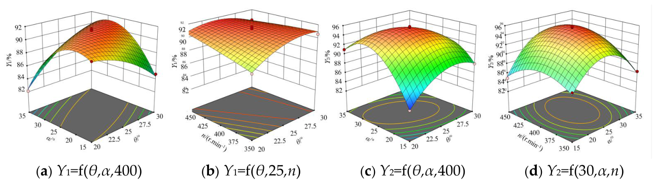
Figure 14.
Field tests.
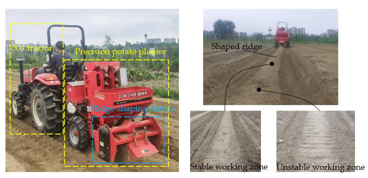

Table 1.
Simulation parameters of ridging knife and soil.
| Parameter | Value | |
|---|---|---|
| Soil | Solid density/g.cm-3 | 2.09 |
| Poisson's ratio | 0.38 | |
| Shear modulus/Pa | 1×10⁶ | |
| Soil-soil | coefficient of restitution | 0.47 |
| Static friction coefficient | 0.67 | |
| Coefficient of kinetic friction | 0.34 | |
| JKR coefficient/J.m-2 | 0.07 | |
| Ridging blade | Poisson's ratio | 0.4 |
| Density/kg.m-3 | 7800 | |
| Shear modulus /Pa | 7.85×10⁹ | |
| Soil-ridging blade | Coefficient of restitution | 0.5 |
| Static friction coefficient | 0.57 | |
| Coefficient of kinetic friction | 0.09 | |
Table 2.
Single-factor experiment grouping table.
| Factor | Experimental levels | Fixed parameters |
|---|---|---|
| θ/° | 24,27,30,33,36 | 400r.min-1,25° |
| n/(r·min-1) | 350,375,400,425,450 | 30°,25° |
| α/° | 10,17.5,25,32.5,40 | 400r.min-1,30° |
Table 3.
Box–Behnken design and experimental results.
| No. | X1/θ(°) | X2/α(°) | X3/n | Y1/(%) | Y2/(%) |
|---|---|---|---|---|---|
| 1 | -1 | -1 | 0 | 90 | 83.6 |
| 2 | 1 | -1 | 0 | 84.8 | 88 |
| 3 | -1 | 1 | 0 | 82.1 | 91 |
| 4 | 1 | 1 | 0 | 89.9 | 84.4 |
| 5 | -1 | 0 | -1 | 88.1 | 89.3 |
| 6 | 1 | 0 | -1 | 90.6 | 87.5 |
| 7 | -1 | 0 | 1 | 91.2 | 90.4 |
| 8 | 1 | 0 | 1 | 90.3 | 90.1 |
| 9 | 0 | -1 | -1 | 88.4 | 87.2 |
| 10 | 0 | 1 | -1 | 86.6 | 86.4 |
| 11 | 0 | -1 | 1 | 87.5 | 84.9 |
| 12 | 0 | 1 | 1 | 88.2 | 89 |
| 13 | 0 | 0 | 0 | 91.5 | 95.2 |
| 14 | 0 | 0 | 0 | 91 | 95.7 |
| 15 | 0 | 0 | 0 | 90.8 | 95.8 |
| 16 | 0 | 0 | 0 | 91.7 | 94.9 |
| 17 | 0 | 0 | 0 | 91.4 | 95.2 |
Table 4.
Field test results.
| No. | Y1/(%) | Y2/(%) |
|---|---|---|
| 1 | 87.9 | 90.6 |
| 2 | 88.2 | 91.0 |
| 3 | 88.5 | 91.8 |
| 4 | 89.0 | 91.3 |
| 5 | 89.4 | 92.3 |
| Mean value | 88.6 | 91.4 |
| Relative error | 3.0 | 4.1 |
Disclaimer/Publisher’s Note: The statements, opinions and data contained in all publications are solely those of the individual author(s) and contributor(s) and not of MDPI and/or the editor(s). MDPI and/or the editor(s) disclaim responsibility for any injury to people or property resulting from any ideas, methods, instructions or products referred to in the content. |
© 2026 by the authors. Licensee MDPI, Basel, Switzerland. This article is an open access article distributed under the terms and conditions of the Creative Commons Attribution (CC BY) license.
Copyright: This open access article is published under a Creative Commons CC BY 4.0 license, which permit the free download, distribution, and reuse, provided that the author and preprint are cited in any reuse.