

Submitted:
09 October 2026
Posted:
12 October 2026
You are already at the latest version
Abstract
This paper examines the nonlinear transient response of porous FGM sandwich beams with elastically restrained ends under thermal environments. Using a refined higher-order shear deformation theory (HSDT), two configurations are analyzed: symmetric and asymmetric cross-sections with temperature-dependent properties and varied porosity distributions.
In asymmetric structures, conventional strong-form approximations omit the boundary moments caused by bending–extension coupling and thermal effects. To address this methodological gap, a multi-term weak-form Galerkin approach is developed, retaining end moments and arbitrary support locations. The formulation is rigorously validated against exact linear solutions and independent nonlinear finite element models.
Results demonstrate that section symmetry dictates the validity of strong-form approximations. For asymmetric beams, ignoring thermal bending leads to an overestimation of peak deflections at elevated temperatures, with deviations amplifying when supports act at the neutral surface. Comprehensive parametric evaluations further elucidate the governing influence of end restraint, porosity, layer thickness, foundation stiffness, and initial imperfections on the dynamic response.
Keywords:
porous FGM
; sandwich beam
; asymmetric cross-section
; HSDT theory
; thermal bending
; Galerkin method
; winkler–pasternak foundation
1. Introduction
Functionally graded materials (FGMs) vary the volume fractions of ceramic and metal smoothly through one or more directions. This gradation avoids the stress concentration and delamination found in conventional laminated composites, while combining the heat resistance of ceramics with the toughness of metals. FGMs are therefore used in thermal barrier components, aerospace structures and nuclear plants. Sandwich construction adds a high bending-stiffness-to-weight ratio, and FGM sandwich beams and plates have been studied extensively for buckling, vibration and dynamic response [1,2,3,4].
Pores may form inside FGMs during fabrication, for example during sintering. Their effect has been modelled with modified rules of mixture for even and uneven distributions [5]. Porosity has since been included in the linear vibration of FGM beams [6,7], the thermal postbuckling and nonlinear vibration of porous FGM beams with elastically restrained ends [8,9], and the nonlinear dynamic response of porous FGM plates on elastic foundations [10].
The in-plane restraint of beam ends strongly affects thermally loaded structures. When the ends cannot move freely, a uniform temperature rise produces axial compressive forces that reduce bending stiffness. This effect has been modelled through an elastic restraint parameter [11], and a growing body of semi-analytical work has applied it to the buckling, vibration and nonlinear transient response of porous FGM beams, plates, shells and sandwich beams in thermal environments [8,9,12,13,14,15]. These studies have clarified how porosity, gradation, temperature, foundation support, initial imperfection and the degree of end restraint govern the global response; for example, end restraint deepens the dynamic deflection at elevated temperature, and initial imperfection can be beneficial at room temperature but detrimental when heated.
Bending–extension coupling gives asymmetric FGM beams a behaviour with no counterpart in homogeneous beams. Their nonlinear vibration differs for positive and negative amplitudes [16,17]. Under uniform heating, simply supported FGM beams bend instead of buckling by bifurcation, whereas clamped beams buckle [18,19,20,21]. Formulations referred to the physical neutral surface remove the coupling from the constitutive equations [22,23], and for immovable simple supports the mid-plane and neutral-surface formulations give different responses because each fixes the structure at a different plane [24]. None of these effects is new, and the present paper does not claim them as such.
Despite this progress, the attention of transient studies has been directed mainly at the global response, and less at a boundary-level detail with a clear physical effect: the moment that bending–extension coupling and the thermal moment create at restrained ends. A widely used semi-analytical approach, adopted in many studies of this class of structures (see, e.g., [8,9,12,13,14,15]), expands the deflection in a single sine mode and projects it by the Galerkin method onto the strong-form equations of motion. This choice is efficient and accurate for symmetric sections. For asymmetric sections, however, the sine mode has zero curvature at the ends and cannot satisfy the end-moment condition, and the constant end moment vanishes when the strong-form equations are differentiated. The beam then behaves as if it were hinged at its neutral surface and free of thermal bending, whatever support conditions are assumed. To the authors’ knowledge, the consequences of this common simplification for the nonlinear transient response of asymmetric porous FGM sandwich beams have not been quantified, and this is the gap the present paper addresses.
The present work uses a refined higher-order shear deformation theory (HSDT), which gives a parabolic shear strain that vanishes at the surfaces and needs no shear correction factor [25,26]. A preliminary check with a quasi-3D theory showed that thickness stretching changes the peak dynamic deflection of Si3N4/SUS304 beams by less than 2% down to L/h = 5, so it is not pursued here.
This paper makes several key contributions: it develops a weak-form, multi-term Galerkin solution based on the HSDT for porous FGM sandwich beams with elastically restrained ends, clearly revealing what the strong-form approximation neglects; it validates this approach using an exact linear solution and an independent nonlinear finite element model; it quantifies the strong-form deviations in frequency and peak deflection by separating the effects of end-reaction coupling stiffness and thermal bending; it properly accounts for the thermal pre-load as an initial equilibrium state to show how the loading sequence affects the response; and it conducts comprehensive parametric studies to determine which previous strong-form trends remain valid for asymmetric sandwich beams.
2. Porous FGM Sandwich Beams
2.1. Geometry
Consider a sandwich beam of length L, unit width b = 1 and total thickness h, resting on a Winkler–Pasternak foundation. The origin of the Cartesian system (x, y, z) lies on the mid-plane at the left end; x runs along the beam and z through the thickness, positive downward. The beam has two face sheets of equal thickness hf and a core of thickness h − 2hf, perfectly bonded. The layer boundaries are shown in Figure 1 and given by
2.2. Type A: FGM Face Sheets and Metal Core
The ceramic volume fraction decreases from each outer surface to its interface, and the core is pure metal. The beam is symmetric about the mid-plane:
2.3. Type B: Metal Top Face, FGM Core, Ceramic Bottom Face
The top face is pure metal, the bottom face is pure ceramic, and the ceramic fraction in the core rises from the upper to the lower interface. The beam is asymmetric about the mid-plane:
In both types the metal fraction is Vm = 1 − Vc, and N ≥ 0 is the volume fraction index.
2.4. Porosity Models
The effective property Peff (Young’s modulus E, thermal expansion coefficient α, mass density ρ) of the porous FGM follows the modified rule of mixture [5], with total pore volume fraction ξ (0 ≤ ξ ≪ 1):
For even porosity ψ(z) = 1 in every FGM layer. For uneven porosity:
- Type A: ψ(z) = (z − h0)/(h1 − h0) in the top face, ψ(z) = 0 in the metal core, and ψ(z) = (z − h3)/(h2 − h3) in the bottom face. Pores are densest at the interfaces.
- Type B: ψ(z) = 1 − 2|z|/(h2 − h1) in the core and ψ(z) = 0 in the homogeneous faces. Pores are densest at the mid-plane.
The porosity distribution is written ψ(z) because f(z) is reserved for the shear shape function of the HSDT in Section 3.
2.5. Temperature-Dependent Properties
The beam is heated uniformly from T0 = 300 K to T, so ΔT = T − T0. The properties of each constituent follow the Touloukian form
with the coefficients of Table 1 [27]. The mass densities are ρc = 2370 kg/m3 for Si3N4 and ρm = 8166 kg/m3 for SUS304. Poisson’s ratio is taken as constant, ν = 0.28, a value commonly adopted for this material pair [15], which also allows direct comparison with published FSDT results. In the HSDT used here, ν enters only through the shear modulus.
P(T) = P0(P−1T−1 + 1 + P1T + P2T2 + P3T3)
3. HSDT Formulation
3.1. Displacement Field
The refined higher-order shear deformation theory splits the deflection into bending and shear parts [25,26]:
The transverse shear strain is parabolic through the thickness and vanishes at z = ±h/2, so no shear correction factor is needed. The initial geometric imperfection is w*(x).
3.2. Strains3.3. Stresses and Resultants
The uniform temperature rise ΔT is applied before the load and acts as a pre-existing axial thermal stress:
The resultants Nx, Mxb, Mxs (weights 1, z, f) and Qxz (weight g) are
With
For the symmetric type A beam B11 = Bs11 = MT = PT = 0. For the asymmetric type B beam all coefficients are non-zero, which is the source of the end-moment effect discussed in Section 3.6.
3.4. Hamilton’s Principle
Axial and rotary inertia are neglected, as is common in this class of analyses [9,15]; neglecting axial inertia is the usual static condensation of hinged-beam models [28]. With the foundation on the bottom surface and the load on the top surface, both deflecting by w, the weak statement of motion is
This weak statement is the starting point of the solution in Section 4.
3.5. Equations of Motion
Integrating by parts gives the strong form:
Equation (14) gives Nx = Nx0, constant along the beam.
3.6. End Conditions and the End Moment
Both ends are hinged and elastically restrained against axial displacement by springs of stiffness c. The hinges and springs act at the height z = zs: zs = 0 places them at the mid-plane, as usually assumed in mid-plane formulations, and zs = z0 = B11/A11 places them at the physical neutral surface [22,23,24]. Moment equilibrium about the hinge and the spring law give
with λ = c/(c + A11): λ = 0 for movable, 0 < λ < 1 for partially movable and λ = 1 for immovable ends. Eliminating ε0 with Nx = Nx0 gives the moment about the hinge as
The term M̂b0 is constant along the beam. In an asymmetric beam hinged at the mid-plane it has two parts: the end reaction acts at the mid-plane while the neutral axis lies at the offset z0, and the thermal moment MT is non-zero. With hinges at the neutral surface the first part vanishes, but M̂b0 = −(MT − z0NT), the thermal moment about the neutral axis, remains. In either case the end condition (17) requires non-zero curvature at the ends, which a sine mode cannot provide.
If Galerkin’s method is applied to the strong form with a one-term sine expansion, as in the approach discussed in Section 1, the constant M̂b0 disappears when differentiated twice and its effect is lost. If it is applied to the weak form (13) with the spring acting at zs, M̂b0 does work on the end rotations of each mode and is retained. Section 5 confirms by an exact solution and by finite elements that the weak form is correct.
4. Solution Procedure
The deflections are expanded in n symmetric sine modes, which satisfy the essential end conditions:
i = 1,3,…,2n − 1
Even modes are not excited by a uniform load and a symmetric imperfection, so they are omitted. The modal deflection is Wi = Wbi + Wsi, and the mid-span deflection is w(L/2) = ΣiWisin(iπ/2). The one-term case (n = 1) corresponds to the solution form commonly used in the literature [9,15]. Unless stated otherwise, zs = 0.
With Nx = Nx0, the membrane strain is ε0 = (Nx0 + NT − B11κb − Bs11κs)/A11, so the moments about the hinge are
Substituting the trial functions into Eq. (18) gives
where μ1 = μ and μi = 0 for i > 1. The modes are coupled only through Nx0.
The weak statement (13) is applied with each mode as test function, and every equation is divided by L/2. With Πi = 4/(iπ):
The terms Πiβi2M̂0 are the work of the constant end moments on the end rotations. A strong-form projection drops them. Through Nx0, M̂b0 contains a term linear in the deflection, so it changes the linear stiffness of an immovable asymmetric beam, not only its nonlinear response. It also contains −MT, which acts as an equivalent thermal load.
Because rotary inertia is neglected, Eqs. (25) and (26) have the same inertia term I0Ẅi. Subtracting them gives n algebraic equations:
With Wbi = Wi − Wsi, these equations are linear in the vector of Wsi for given Wi, since Nx0 is linear in Wsi. They are solved at every evaluation, which leaves n second-order equations I0Ẅi = −Fbi(W), where Fbi is the non-inertial part of Eq. (25).
The temperature rise is applied before the load. When heating alone deflects the beam (type B, or μ ≠ 0 with λ > 0), the thermal equilibrium state is found by Newton–Raphson iteration with q = 0 and used as the initial state. The load is then applied suddenly at t = 0. Some studies apply heating and loading together from a flat beam at rest, W(0) = Ẇ(0) = 0; for comparison with such results, zero initial conditions are also used where stated.
4.1. Time Integration and Frequencies
The 2n first-order equations are integrated with the classical fourth-order Runge–Kutta scheme (RK4). The step is the smaller of 0.5/ωmax and T1/400, where ωmax is the highest linear frequency in the expansion and T1 the fundamental period. The results are cross-checked with an implicit Radau solver. Natural frequencies follow from the eigenvalues of the linearised system about the thermal equilibrium state. The number of terms n is fixed by the convergence study of Section 5.
5. Verification
The weak-form solution is verified against published results (Section 5.1 and Section 5.3), an exact solution (Section 5.2) and an independent nonlinear finite element model (FE)(Section 5.5). Single-layer FGM beams are obtained from type B with hf = 0. Frequencies are non-dimensionalised as ω̄ = ω(L2/h)√(ρm/Em), with metal properties at the current temperature.
5.1. Linear Frequencies Against Published Results
Table 2 compares the fundamental frequency of Al/Al2O3 beams (Em = 70 GPa, ρm = 2702 kg/m3, Ec = 380 GPa, ρc = 3960 kg/m3, ν = 0.3; L/h = 20, N = 2, ΔT = 0). In the published studies these values are reported for immovable ends; as Section 5.2 shows, they coincide with the movable-end value. They are therefore compared with the present HSDT at λ = 0. The agreement between the results is remarkably high.
5.2. Exact Solution for Immovable Ends
To settle which treatment of the restrained end is correct, the linear free vibration of a hinged Euler–Bernoulli FGM beam is solved exactly. With u = 0 at both ends, the axial force is constant, N = −(B11/L)[w′(L) − w′(0)], and the end condition M = 0 becomes
The characteristic equation is solved for the lowest root. Setting B11 = 0 in the end condition gives the movable-end value. The results are listed in Table 3.
Three observations follow:
The strong-form result is the same with and without end restraint. It lies within 0.3% of the exact movable value, the gap being the shear deformation that the exact Euler–Bernoulli solution ignores.
The weak-form result converges from above to the exact immovable value, as expected of a Ritz-type approximation. With five terms it is within 0.1% of the exact solution.
The strong-form deviation grows with porosity, from 10% to 19% for even pores, because pores lower A11 more than they lower the coupling ratio B112/(A11D̃11).
With the hinges at the neutral surface (zs = z0), the weak form gives ω̄ = 3.8407 for ξ = 0, identical to the movable-end value, because the coupling term of Eq. (18) vanishes. Immovable-end frequencies obtained with one-term strong-form solutions therefore correspond to hinges at the neutral surface, or equivalently to movable ends, rather than to mid-plane hinges. This is a property of the approximation rather than of any particular calculation; it affects only asymmetric beams, and it also explains why independently obtained benchmark values agree closely with one another (Table 2).
5.3. Thermal Environment
Table 4 repeats the Si3N4/SUS304 case of Ebrahimi and Jafari [6] (L/h = 20, ΔT = 80 K, λ = 1) with temperature-dependent properties. The strong-form results agree with both references, which confirms the material data and the thermal model. The weak form diverges only marginally for graded beams (N > 0). The effect is smaller than for Al/Al2O3 because the stiffness contrast of Si3N4/SUS304 is lower, which reduces the coupling ratio.
5.4. Nonlinear Transient Response and Convergence
The nonlinear transient response is checked against published strong-form results for FGM sandwich beams [15] (L/h = 20, N = 2, hf/h = 0.2, even porosity, λ = 1, T = 300 K, q = 106 N/m2, zero initial conditions) in Table 5. The present strong-form solution reproduces the published curves, which confirms that the two implementations are equivalent. For the symmetric type A beam both forms agree, as expected. For type B, the weak form slightly reduces the peak at room temperature.
Table 6 shows convergence in the number of terms for a type B beam (N = 2, hf/h = 0.2, uneven, ξ = 0.2, λ = 1, zero initial conditions). Three terms give converged peaks, and one term remains extremely close to the converged value. The strong form overestimates the peak by a minor margin at 300 K and by 23% at 400 K, where the thermal end moment adds to the coupling effect. The RK4 solution with n = 3 agrees with an implicit Radau solution (with a very tight relative tolerance) within an imperceptible margin over 5 ms. All results in Section 6 use n = 3.
5.5. Independent Finite Element Verification
The exact solution of Section 5.2 is linear and isothermal. To verify the nonlinear transient response in a thermal environment, an independent model was built that does not use sine modes. The beam is discretised with 40 Euler–Bernoulli elements with Hermite cubic deflection. Because axial inertia is neglected, Nx is constant and the axial displacement is condensed exactly through Eq. (18). The end-moment conditions (17) are natural conditions of the finite element weak form and are satisfied by the solution itself. The thermal equilibrium state is found by Newton–Raphson iteration, and the response to the suddenly applied load is integrated with the Newmark average-acceleration method (Δt = 2 μs) with Newton iterations at each step. The peak deflection is unchanged to five digits between 10 and 80 elements.
For a like-for-like comparison, the Ritz solution is evaluated in the same Euler–Bernoulli limit by making the shear stiffness As55 very large. Table 7 and Figure 2 show the results. The finite element and weak-form solutions exhibit an exceptionally close agreement in peak deflection and thermal pre-deflection, whereas the strong-form approximation departs by a notable margin for type B. For type A the three solutions coincide. The last column shows that shear deformation adds an imperceptible effect (less than a minor fraction) a L/h = 20.
6. Results and Discussion
Unless stated otherwise: Si3N4/SUS304, h = 0.02 m, L/h = 20, q = 106 N/m2, N = 2, hf/h = 0.2, uneven porosity with ξ = 0.2, λ = 1, (K1, K2) = (100, 10), μ = 0 and T = 400 K, where K1 = 12k1L4/(Em0h3) and K2 = 12k2L2/(Em0h3) as in [15]. The foundation keeps the beams below thermal buckling up to 700 K; without it, type A buckles thermally near 450 K. The weak form uses n = 3 terms and starts from the thermal equilibrium state (Section 4.6). The strong form denotes the one-term strong-form projection [9,15], whose equilibrium state is flat when μ = 0. The hinges are at the mid-plane except in Section 6.3. The peak is the maximum mid-span deflection W/h over 6 ms, measured from the flat beam.
6.1. Temperature
For the symmetric type A beam the two forms coincide at every temperature (Figure 3a), because M̂b0 = M̂s0 = 0. For type B they separate as the temperature rises (Figure 3b). The strong form overestimates the peak by by a minor margin at 300 K, and by a progressively larger and notable margin at 400 K, 500 K and 600 K. The gap narrows to a lower margin at 700 K. Near the thermal stability limit the load-induced amplitude of the pre-bent beam grows faster than that of the strong form (0.49 against 0.36), which partly offsets the pre-deflection. In the weak form, heating alone bends the type B beam upward, by 0.009h at 400 K, 0.024h at 500 K and 0.18h at 700 K. The strong form has no such pre-deflection.
6.2. End Restraint and the Source of the Difference
At 300 K the restraint hardly matters, because no thermal force develops (Figure 4a). At 500 K the peak grows with λ in both forms, though the strong-form results remain higher across all values of λ, including λ = 0 (0.076 against 0.036). With movable ends Nx0 = 0, so the remaining end moment is the thermal moment alone: a free asymmetric beam bends under uniform heating, as a bimetal strip does.
Figure 4b separates the two parts of the weak-form response. The load-induced amplitude (peak minus W0) exhibits an exceptionally close alignment with the strong-form predictions across all values of λ. Therefore, the total discrepancy observed in Figure 4a is entirely attributed to the thermal pre-deflection W0, which decreases in magnitude from 0.040h at λ = 0 to 0.024h at λ = 1 as the restraint resists bending.
For Si3N4/SUS304 beams the omitted end moment thus acts mainly through the thermal moment. Its linear stiffening effect is small here, consistent with the minimal differences shown in in Table 4, whereas it dominates for the higher-contrast Al/Al2O3 beams of Table 3. Which mechanism matters depends on the stiffness contrast and on the temperature.
6.3. Support Location
Figure 5 repeats the temperature study of type B with the hinges at the neutral surface (zs = z0). The thermal moment about the neutral axis is larger than the end moment of the mid-plane case, and the upward pre-deflection is about three times larger: −0.024h at 400 K, −0.069h at 500 K and −0.35h at 700 K. The total peak therefore falls with temperature, to 0.069 at 400 K and 0.059 at 500 K, while the strong form predicts 0.092 and 0.125. The load-induced amplitude remains within an exceptionally close margin of the strong-form value up to 550 K and deviates near the stability limit (Figure 5b).
Therefore, the strong-form deviation does not disappear when the supports are placed at the neutral surface; it becomes larger. Because the response depends on where the hinges act, a study of asymmetric beams with restrained ends must state the support plane, as also observed for plates in [24].
6.4. Initial Conditions
How the thermal state is introduced changes the response substantially (Figure 6). If heating and loading start together from a flat beam at rest, the thermal bending is itself excited dynamically and the weak-form peak is 0.077. Starting from the thermal equilibrium state it is 0.101, oscillating between W0 = −0.024 and 0.101. The amplitude of 0.125 is the same as that of the strong form, but the strong form starts from zero. A study must therefore state which loading sequence it models. Since the problem statement applies the temperature before the load, the equilibrium start is used throughout.
6.5. Porosity
At 400 K with the base foundation, pores increase the peak of type A, from 0.099 at ξ = 0 to 0.105 at ξ = 0.3 for even pores, and less for uneven pores (0.101). They slightly decrease it for type B, from 0.085 to 0.081 (Figure 7a). Separating the response shows why. For uneven pores, the thermal pre-deflection of type B hardly changes (−0.0092h to −0.0086h as ξ goes from 0 to 0.3), whereas the load-induced amplitude falls from 0.094 to 0.090. At 300 K the same pores raise the peak slightly (0.0726 to 0.0729 for uneven and to 0.0745 for even pores). Pores lower E and with it both the bending stiffness and the axial thermal force NT; at 400 K the reduction of the thermal softening outweighs the loss of stiffness. This is consistent with earlier findings that porosity is detrimental at room temperature without a foundation [15], and shows that the sign of the porosity effect depends on the thermal state.
The strong-form deviation in Figure 7b remains within a minor margin at 300 K and expands to a notable and significant margin at 400 K, remaining almost entirely independent of ξ. This contrasts with the linear Al/Al2O3 results of Table 3, where porosity amplified the deviation, because here the deviation comes mostly from the thermal pre-deflection rather than from coupling stiffness.
6.6. Volume Fraction Index and Face-Sheet Thickness
A larger N lowers the ceramic content and raises the peak of both types (Figure 8a): from 0.089 to 0.106 for type A and from 0.080 to 0.085 for type B as N goes from 0 to 10. The strong form overestimates the type B peak by a notable and steady margin over this range.
Thicker face sheets lower the peak of type A, from 0.106 at hf/h = 0.05 to 0.095 at 0.35, in line with earlier results [15] (Figure 8b). For type B the two forms disagree qualitatively. The strong form predicts almost no sensitivity to hf/h (0.093 to 0.092), consistent with previously reported strong-form results [15]. The weak form gives a a moderate decrease, from 0.086 to 0.081. Thicker metal and ceramic faces increase the asymmetry and hence the thermal moment and the upward pre-deflection. The weak sensitivity of type B predicted by the strong-form approximation therefore reflects the omitted thermal moment rather than a property of the beam.
6.7. Initial Imperfection
The imperfection lowers the peak at room temperature and raises it at 400 K for both types (Figure 9). For type A it goes from 0.077 to 0.063 at 300 K and from 0.100 to 0.136 at 400 K as μ increases from 0 to 0.3. For type B the corresponding values are 0.073 to 0.056 and 0.083 to 0.107. The strong form shows the same trends remaining higher by a notable and consistent margin at 400 K. The reversal reported in earlier strong-form studies [15] therefore also holds in the weak-form formulation: at room temperature the imperfection stiffens the beam through the membrane coupling, while at elevated temperature the axial thermal force acting on the imperfection behaves as an additional load.
6.8. Foundation Stiffness
Table 8 lists the peak deflection for several foundations at 400 K. Stiffer foundations lower the peak of both types, by a factor of about 6.5 for type A and 5.3 for type B between no foundation and (K1, K2) = (150, 20). The shear layer is particularly effective: adding K2 = 10 to K1 = 100 reduces the peak by by a substantial and marked margin. The strong-form overestimate for type B stays within a notable and consistent margin across all foundations.
7. Conclusions
The nonlinear transient response of porous FGM sandwich beams with elastically restrained ends in thermal environments has been analysed with a refined HSDT and a weak-form, multi-term Galerkin solution that retains the moments at the beam ends. The main conclusions are:
- In asymmetric beams, the moment at a restrained hinged end depends on the axial reaction, through bending–extension coupling, and on the thermal moment. These effects are well documented in static and free-vibration studies, but a one-term Galerkin projection of the strong-form equations, a common simplification in transient analyses, does not capture them; the beam then behaves as if hinged at the neutral surface and free of thermal bending. For immovable Al/Al2O3 FGM beams hinged at the mid-plane this underestimates the fundamental frequency by a notable and progressive margin, with the deviation growing with porosity. The weak form converges to the exact value within an exceptionally tight margin using five term, and agrees with an independent nonlinear finite element model within a similarly close margin in the transient response.
- For symmetric sandwich beams (type A) the end moment vanishes, and the strong and weak forms give identical results. Published results for such beams are unaffected.
- For asymmetric Si3N4/SUS304 sandwich beams (type B), the strong form overestimates the peak dynamic deflection by a minor margin at 300 K, notable margin at 400 K and and a substantial margin between 500 and 650 K. The load-induced amplitude is almost the same in both forms; the difference is the upward thermal pre-deflection caused by the thermal moment, which the strong form omits. In higher-contrast material pairs the coupling stiffness contributes as well.
- The support plane matters. With hinges at the neutral surface the coupling term vanishes but the thermal moment about the neutral axis remains, the thermal pre-deflection triples, and the strong-form deviation grows (0.059 against 0.125 in peak deflection at 500 K). Studies of asymmetric beams with restrained ends should state where the supports act.
- The order in which heat and load are applied matters. Starting from the thermal equilibrium state, rather than applying heating and loading together, changes the peak deflection of type B by a marked and significant margin at 500 K. Studies should state which sequence they model.
- For asymmetric beams, some trends obtained with strong-form approximations change while others remain valid. The weak sensitivity of type B beams to the face-sheet thickness does not persist: the weak-form peak falls by a moderate margin as hf/h increases from 0.05 to 0.35. Other trends remain valid: initial imperfection still reduces the dynamic deflection at room temperature and increases it at elevated temperature, and a larger volume fraction index still increases it.
- The effect of porosity depends on the thermal state. At 400 K with a supporting foundation, pores increase the peak deflection of type A beams but slightly reduce that of type B beams, because they reduce the axial thermal force more than the bending stiffness.
- Three sine terms yield converged nonlinear transient responses. Thickness stretching, checked using a quasi-3D theory, changes the peak deflection of the Si3N4/SUS304 beams by an imperceptible and minimal margin down to L/h = 5, indicating that a refined HSDT is fully adequate for this class of problems.
The current findings assume an isothermal temperature distribution through the thickness, the absence of damping, and neglected axial or rotary inertia. Incorporating through-thickness temperature gradients—which introduce thermal moments to symmetric beams as well—alongside damping effects and experimental validation represent natural directions for future extensions.
8. Patents
Funding
This research was funded by the Deanship of Graduate Studies and Scientific Research, Taif University, Saudi Arabia.
Data Availability Statement
The Python code used to generate all results, including the finite element model of Section 5.5, is available from the author on reasonable request.
Acknowledgments
The author would like to acknowledge the Deanship of Graduate Studies and Scientific Research, Taif University for funding this work.
Conflicts of Interest
“The authors declare no conflicts of interest.”.
Abbreviations
The following abbreviations are used in this manuscript:
| FGM | Functionally graded material |
| FSDT | First-order shear deformation theory |
| HSDT | Higher-order shear deformation theory |
| EB | Euler–Bernoulli |
| FE | Finite element |
| RK4 | Fourth-order Runge–Kutta method |
| Al2O3 | Alumina (aluminium oxide) |
| Si3N4 | Silicon nitride |
| SUS304 | Type 304 austenitic stainless steel |
References
- Zenkour, A.M. A comprehensive analysis of functionally graded sandwich plates: Part 2 – Buckling and free vibration. Int. J. Solids Struct. 2005, 42(18–19), 5243–5258. [Google Scholar] [CrossRef]
- Neves, A.M.A.; Ferreira, A.J.M.; Carrera, E.; Cinefra, M.; Roque, C.M.C.; Jorge, R.M.N.; Soares, C.M.M. Static, free vibration and buckling analysis of isotropic and sandwich functionally graded plates using a quasi-3D higher-order shear deformation theory and meshless technique. Compos. Part B Eng. 2013, 44(1), 657–674. [Google Scholar] [CrossRef]
- Wang, Z.-X.; Shen, H.-S. Nonlinear dynamic response of sandwich plates with FGM face sheets resting on elastic foundations in thermal environments. Ocean Eng. 2013, 57, 99–110. [Google Scholar] [CrossRef]
- Su, Z.; Jin, G.; Wang, Y.; Ye, X. A general Fourier formulation for vibration analysis of functionally graded sandwich beams with arbitrary boundary condition and resting on elastic foundations. Acta Mech. 2016, 227, 1493–1514. [Google Scholar] [CrossRef]
- Wattanasakulpong, N.; Ungbhakorn, V. Linear and nonlinear vibration analysis of elastically restrained ends FGM beams with porosities. Aerosp. Sci. Technol. 2014, 32(1), 111–120. [Google Scholar] [CrossRef]
- Ebrahimi, F.; Jafari, A. A higher-order thermomechanical vibration analysis of temperature-dependent FGM beams with porosities. J. Eng. 2016, 2016, 9561504. [Google Scholar] [CrossRef]
- Turan, M.; Yaylaci, E.U.; Yaylaci, M. Free vibration and buckling of functionally graded porous beams using analytical, finite element, and artificial neural network methods. Arch. Appl. Mech. 2023, 93, 1351–1372. [Google Scholar] [CrossRef]
- Thinh, N.V.; Tung, H.V. Thermal buckling and postbuckling of porous FGM beams with elastically restrained ends resting on nonlinear elastic foundations. Int. J. Comput. Mater. Sci. Eng. 2024, 2450033. [Google Scholar] [CrossRef]
- Anh, N.D.; Thinh, N.V.; Tung, H.V. Nonlinear vibration analysis of geometrically imperfect FGM Timoshenko beams with porosity and elastically restrained ends in thermal environments. Mech. Based Des. Struct. Mach. 2024, 52(12), 10148–10169. [Google Scholar] [CrossRef]
- Duc, N.D.; et al. Nonlinear dynamic response of functionally graded porous plates on elastic foundation subjected to thermal and mechanical loads. J. Appl. Comput. Mech. 2018, 4(4), 245–259. [Google Scholar] [CrossRef]
- Librescu, L.; Lin, W. Vibration of thermomechanically loaded flat and curved panels taking into account geometric imperfections and tangential edge restraints. Int. J. Solids Struct. 1997, 34(17), 2161–2181. [Google Scholar] [CrossRef]
- Tung, H.V.; Long, V.T.; Thu, D.T.N. Thermally induced nonlinear instability of functionally graded plates including pores and elastic edge restraint. J. Sci. Transp. Technol. 2026, 6(2), 37–55. [Google Scholar] [CrossRef]
- Thinh, N.V.; Son, B.N.; Tung, H.V. Nonlinear dynamical response of FG sandwich plates with pores and flexibly constrained boundaries in thermal environments. J. Sci. Transp. Technol. 2026, 6(2), 1–18. [Google Scholar] [CrossRef]
- Thinh, N.V.; Tung, H.V. Nonlinear thermomechanical transient response of FGM circular plates and shallow spherical caps with porosities and tangentially restrained edges. J. Aerosp. Eng. 2026, 39(2), 04025140. [Google Scholar] [CrossRef]
- Huong, V.T.T.; Tung, H.V.; Tam, V.D. Nonlinear transient response of porous FGM sandwich beams with elastically restrained ends in a thermal environment. J. Sci. Transp. Technol. 2026, 6(4), 194–213. [Google Scholar] [CrossRef]
- Kitipornchai, S.; Ke, L.L.; Yang, J.; Xiang, Y. Nonlinear vibration of edge cracked functionally graded Timoshenko beams. J. Sound Vib. 2009, 324(3), 962–982. [Google Scholar] [CrossRef]
- Ke, L.L.; Yang, J.; Kitipornchai, S. An analytical study on the nonlinear vibration of functionally graded beams. Meccanica 2010, 45(6), 743–752. [Google Scholar] [CrossRef]
- Li, S.R.; Zhang, J.H.; Zhao, Y.G. Thermal post-buckling of functionally graded material Timoshenko beams. Appl. Math. Mech. (English Edition) 2006, 27(6), 803–810. [Google Scholar] [CrossRef]
- Kiani, Y.; Eslami, M.R. Thermomechanical buckling of temperature-dependent FGM beams. Lat. Am. J. Solids Struct. 2013, 10(2), 223–246. [Google Scholar] [CrossRef]
- Ma, L.S.; Lee, D.W. Exact solutions for nonlinear static responses of a shear deformable FGM beam under an in-plane thermal loading. Eur. J. Mech. – A/Solids 2012, 31, 13–20. [Google Scholar] [CrossRef]
- Mao, L.J.; Ma, L.S. Nonlinear static responses of FGM beams under non-uniform thermal loading. Eng. Mech. 2017, 34(6), 1–8. [Google Scholar]
- Zhang, D.G. Nonlinear bending analysis of FGM beams based on physical neutral surface and high order shear deformation theory. Compos. Struct. 2013, 100, 121–126. [Google Scholar] [CrossRef]
- Zhang, D.G. Thermal post-buckling and nonlinear vibration analysis of FGM beams based on physical neutral surface and high order shear deformation theory. Meccanica 2014, 49, 283–293. [Google Scholar] [CrossRef]
- Melaibari; Mohamed, S.A.; Assie, A.E.; Shanab, R.A.; Eltaher, M.A. Mathematical and physical analyses of middle/neutral surfaces formulations for static response of bi-directional FG plates with movable/immovable boundary conditions. Mathematics 2023, 11(1), 2. [Google Scholar] [CrossRef]
- Thai, H.T.; Vo, T.P. Bending and free vibration of functionally graded beams using various higher-order shear deformation beam theories. Int. J. Mech. Sci. 2012, 62(1), 57–66. [Google Scholar] [CrossRef]
- Vo, T.P.; Thai, H.-T.; Nguyen, T.-K.; Inam, F.; Lee, J. A quasi-3D theory for vibration and buckling of functionally graded sandwich beams. Compos. Struct. 2015, 119, 1–12. [Google Scholar] [CrossRef]
- Reddy, J.N.; Chin, C.D. Thermomechanical analysis of functionally graded cylinders and plates. J. Therm. Stress. 1998, 21(6), 593–626. [Google Scholar] [CrossRef]
- Sorokin, S.; Lenci, S. A novel view on the canonical ‘stretching-due-to-bending’ nonlinear effect: A slightly curved beam. Eur. J. Mech. – A/Solids 2024, 103, 105171. [Google Scholar] [CrossRef]
- Hadji, L.; Zouatnia, N.; Bernard, F. An analytical solution for bending and free vibration responses of functionally graded beams with porosities: Effect of the micromechanical models. Struct. Eng. Mech. 2019, 69(2), 231–241. [Google Scholar]
Figure 1.
(a) Porous FGM sandwich beam on a Winkler–Pasternak foundation, hinged and elastically restrained at the ends; (b), (c) through-thickness ceramic volume fraction Vc and pore density ψ for types A and B (N = 2, hf/h = 0.2).
Figure 1.
(a) Porous FGM sandwich beam on a Winkler–Pasternak foundation, hinged and elastically restrained at the ends; (b), (c) through-thickness ceramic volume fraction Vc and pore density ψ for types A and B (N = 2, hf/h = 0.2).
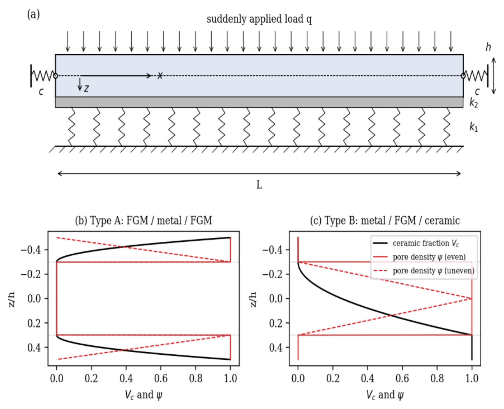
Figure 2.
Type B at 500 K, λ = 1: mid-span deflection from finite elements and from the weak- and strong-form Galerkin solutions (Euler–Bernoulli kinematics).
Figure 2.
Type B at 500 K, λ = 1: mid-span deflection from finite elements and from the weak- and strong-form Galerkin solutions (Euler–Bernoulli kinematics).
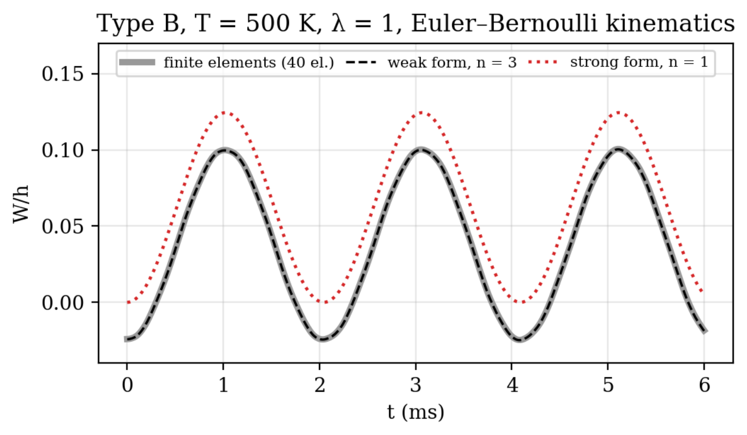
Figure 3.
Peak deflection against temperature: (a) type A, (b) type B, with the thermal pre-deflection of the weak form.
Figure 3.
Peak deflection against temperature: (a) type A, (b) type B, with the thermal pre-deflection of the weak form.
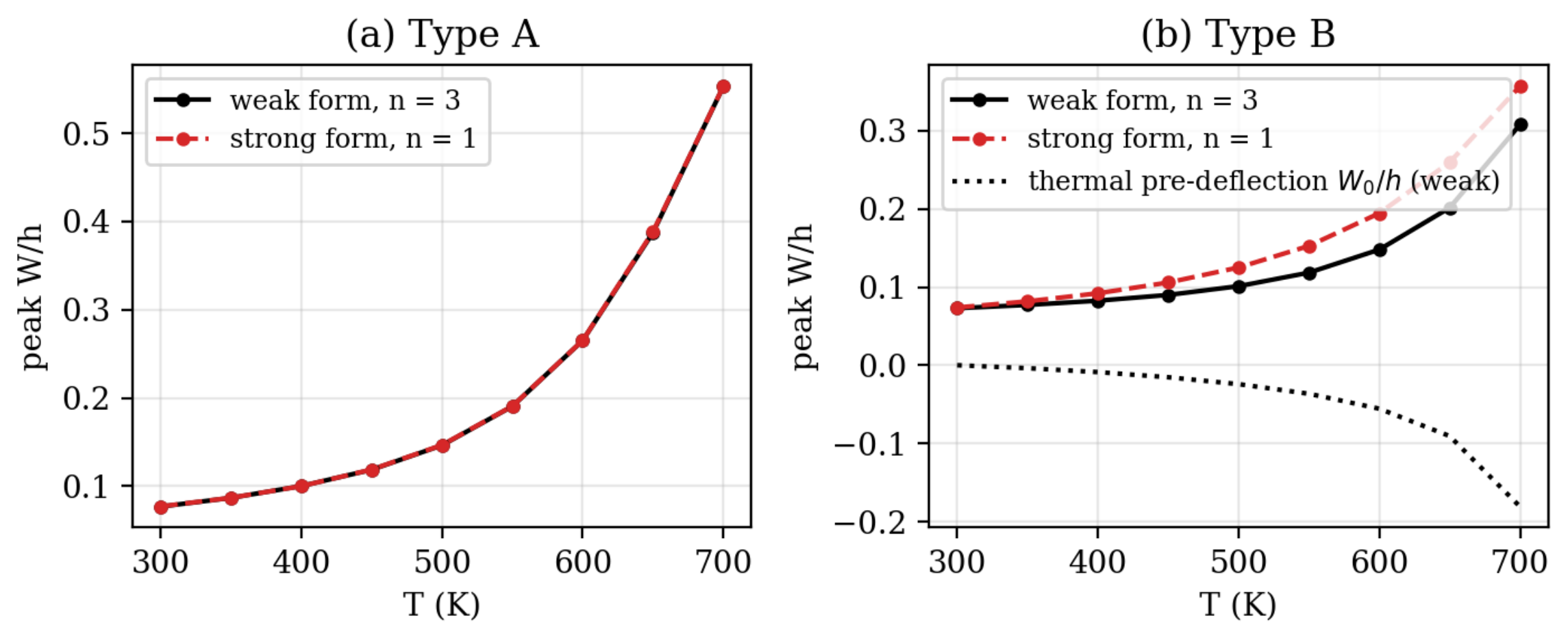
Figure 4.
Type B: (a) peak deflection against the end-restraint parameter λ at 300 and 500 K; (b) at 500 K, thermal pre-deflection and load-induced amplitude.
Figure 4.
Type B: (a) peak deflection against the end-restraint parameter λ at 300 and 500 K; (b) at 500 K, thermal pre-deflection and load-induced amplitude.
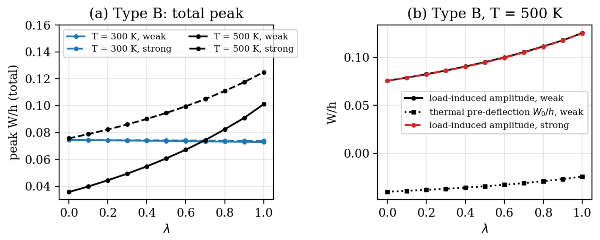
Figure 5.
Type B, λ = 1: effect of the support plane. (a) Total peak deflection and thermal pre-deflection; (b) load-induced amplitude.
Figure 5.
Type B, λ = 1: effect of the support plane. (a) Total peak deflection and thermal pre-deflection; (b) load-induced amplitude.
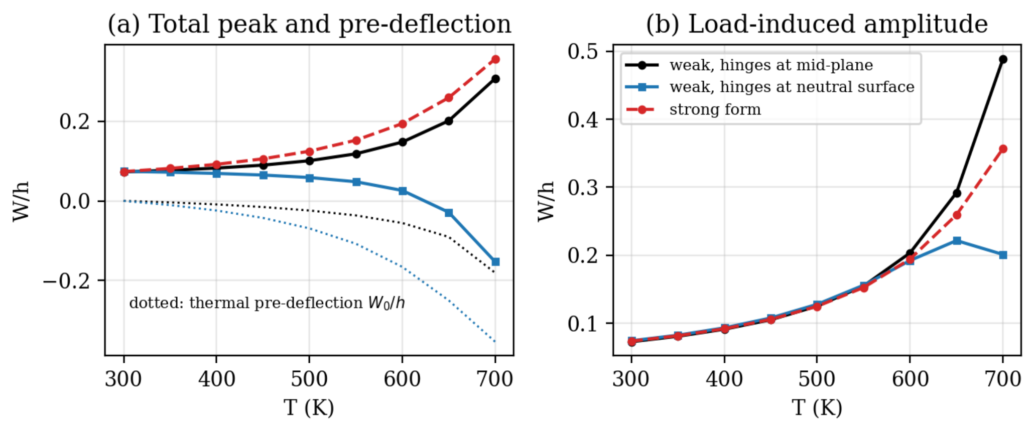
Figure 6.
Type B at 500 K, λ = 1: time histories of the mid-span deflection.
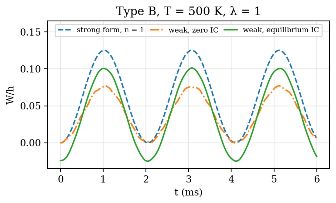
Figure 7.
(a) Peak deflection against the pore volume fraction ξ (weak form); (b) strong-form deviation in the peak for type B.
Figure 7.
(a) Peak deflection against the pore volume fraction ξ (weak form); (b) strong-form deviation in the peak for type B.
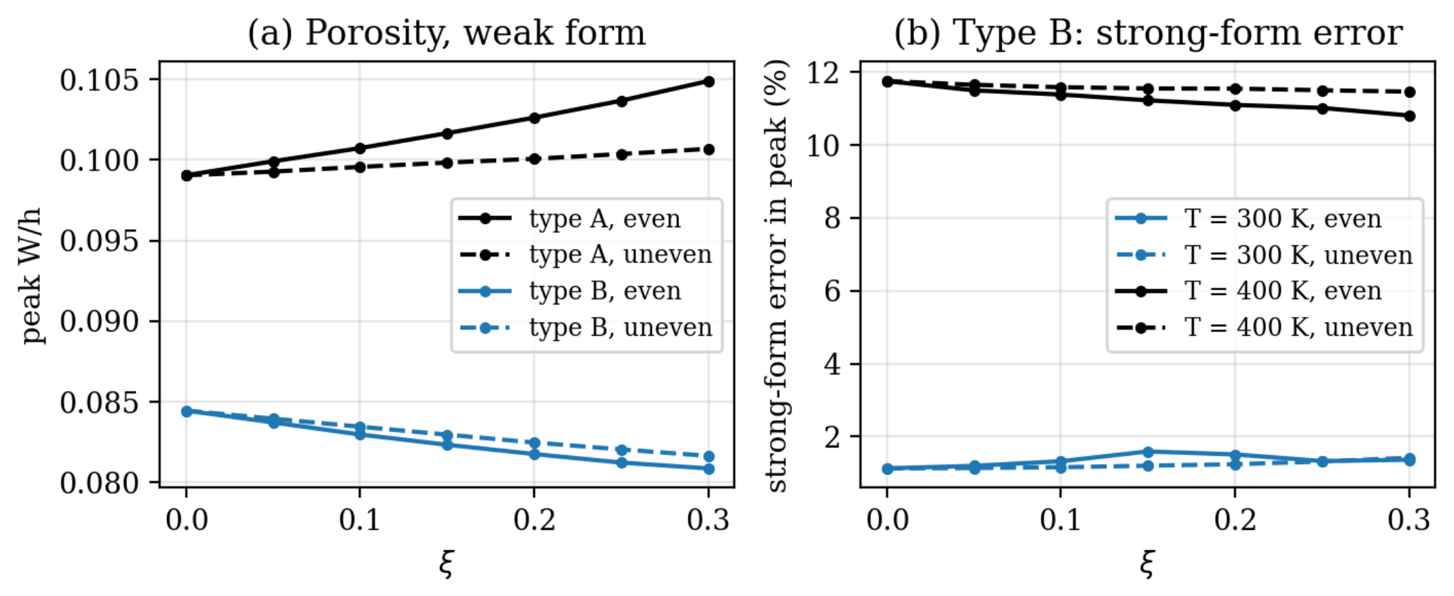
Figure 8.
Peak deflection against (a) the volume fraction index N and (b) the face-sheet thickness ratio hf/h.
Figure 8.
Peak deflection against (a) the volume fraction index N and (b) the face-sheet thickness ratio hf/h.
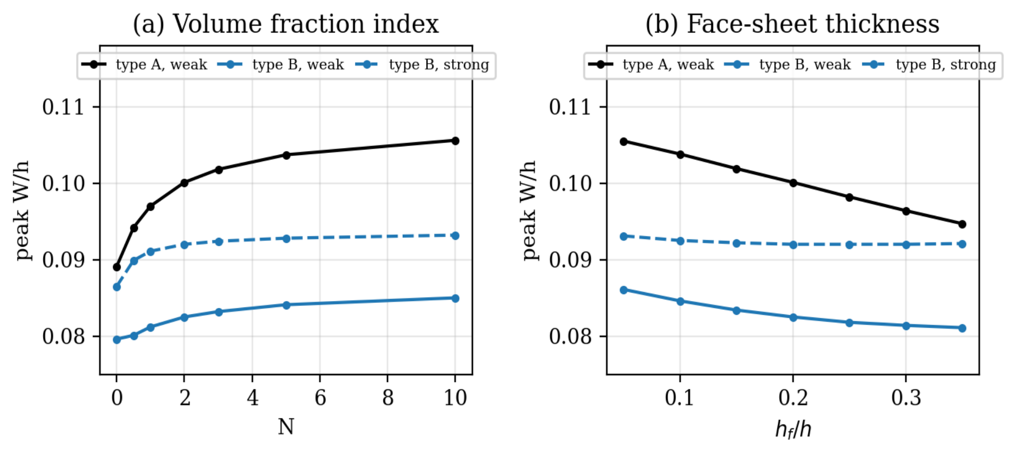
Figure 9.
Peak deflection against the imperfection amplitude μ at 300 and 400 K: (a) type A, (b) type B.
Figure 9.
Peak deflection against the imperfection amplitude μ at 300 and 400 K: (a) type A, (b) type B.
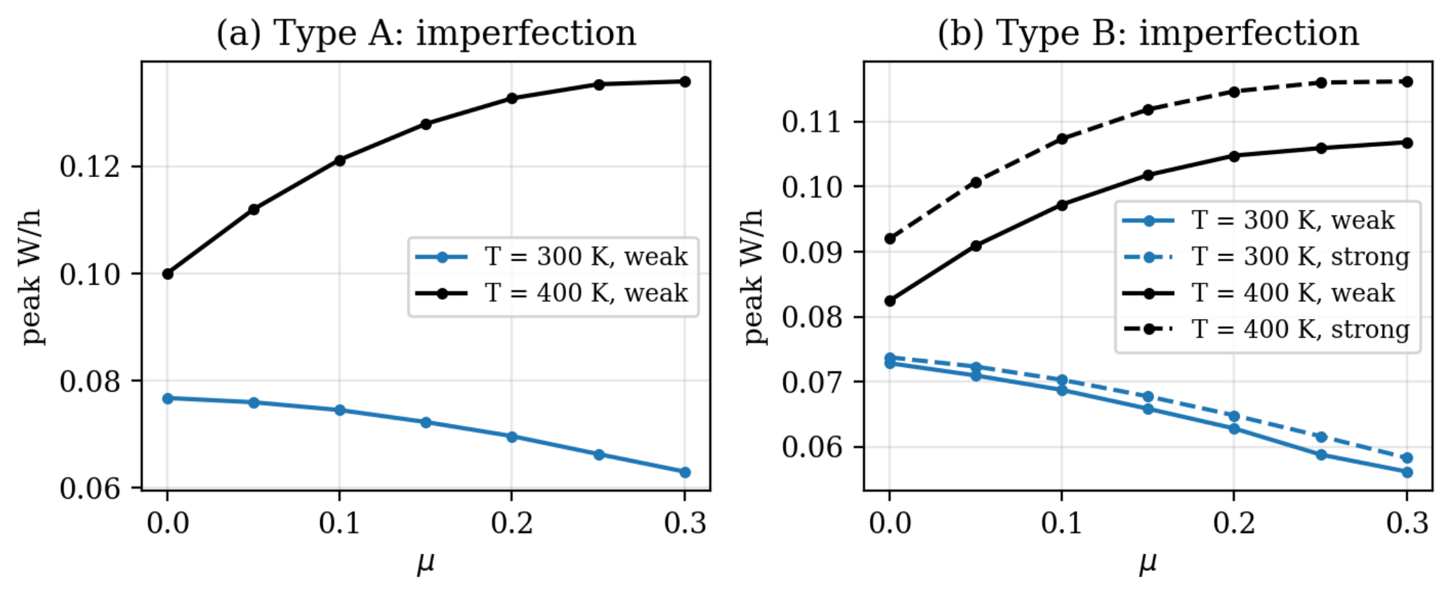

Table 1.
Temperature-dependent coefficients of Si3N4 and SUS304 [27].
Table 1.
Temperature-dependent coefficients of Si3N4 and SUS304 [27].
| Material | Property | P0 | P−1 | P1 | P2 | P3 |
| Si3N4 | E (Pa) | 348.43×10⁹ | 0 | −3.070×10⁻⁴ | 2.160×10⁻⁷ | −8.946×10⁻¹¹ |
| Si3N4 | α (1/K) | 5.8723×10⁻⁶ | 0 | 9.095×10⁻⁴ | 0 | 0 |
| SUS304 | E (Pa) | 201.04×10⁹ | 0 | 3.079×10⁻⁴ | −6.534×10⁻⁷ | 0 |
| SUS304 | α (1/K) | 12.330×10⁻⁶ | 0 | 8.086×10⁻⁴ | 0 | 0 |
Table 2.
ω̄ of Al/Al2O3 beams, L/h = 20, N = 2.
| Porosity | ξ | Turan et al. [7] | Hadji et al. [29] | Huong et al. [15] | Present HSDT (λ = 0) |
| Even | 0 | 3.8368 | 3.8361 | 3.8413 | 3.8407 |
| Even | 0.1 | 3.6340 | 3.6335 | 3.6386 | 3.6380 |
| Even | 0.2 | 3.3128 | 3.3123 | 3.3173 | 3.3167 |
| Uneven | 0.1 | 3.8235 | 3.8226 | 3.8283 | 3.8272 |
| Uneven | 0.2 | 3.8017 | 3.8004 | 3.8066 | 3.8051 |
Table 3.
ω̄ of Al/Al2O3 beams with immovable ends (λ = 1), L/h = 20, N = 2. EB: Euler–Bernoulli.
| Porosity | ξ | Exact EB, movable | Exact EB, immovable | Strong form, n = 1 | Weak form, n = 1 | Weak form, n = 5 | Strong-form deviation |
| Even | 0 | 3.8518 | 4.2877 | 3.8407 | 4.2966 | 4.2772 | −10.2% |
| Even | 0.1 | 3.6478 | 4.2144 | 3.6380 | 4.2437 | 4.2080 | −13.5% |
| Even | 0.2 | 3.3244 | 4.0897 | 3.3167 | 4.1686 | 4.0931 | −19.0% |
| Uneven | 0.1 | 3.8387 | 4.3257 | 3.8272 | 4.3399 | 4.3154 | −11.3% |
| Uneven | 0.2 | 3.8169 | 4.3648 | 3.8051 | 4.3865 | 4.3549 | −12.6% |
Table 4.
ω̄ of Si3N4/SUS304 beams, L/h = 20, ΔT = 80 K, λ = 1.
| Porosity, ξ | Source | N = 0 | N = 0.5 | N = 1 | N = 2 | N = 5 |
| Even, 0 | Ebrahimi and Jafari [6] | 5.4349 | 3.4341 | 2.8884 | 2.4999 | 2.1873 |
| Even, 0 | Huong et al. [15] | 5.4393 | 3.4373 | 2.8912 | 2.5027 | 2.1900 |
| Even, 0 | Present, strong form | 5.4397 | 3.4378 | 2.8914 | 2.5027 | 2.1898 |
| Even, 0 | Present, weak form (n = 5) | 5.4397 | 3.4581 | 2.9244 | 2.5373 | 2.2088 |
| Even, 0.2 | Ebrahimi and Jafari [6] | 7.1036 | 3.8301 | 3.1215 | 2.6493 | 2.2933 |
| Even, 0.2 | Huong et al. [15] | 7.1093 | 3.8339 | 3.1248 | 2.6523 | 2.2964 |
| Even, 0.2 | Present, strong form | 7.1098 | 3.8344 | 3.1250 | 2.6523 | 2.2960 |
| Even, 0.2 | Present, weak form (n = 5) | 7.1098 | 3.8641 | 3.1726 | 2.7023 | 2.3237 |
| Uneven, 0.2 | Ebrahimi and Jafari [6] | 6.2757 | 3.7669 | 3.1456 | 2.7163 | 2.3817 |
| Uneven, 0.2 | Huong et al. [15] | 6.2823 | 3.7713 | 3.1495 | 2.7201 | 2.3856 |
| Uneven, 0.2 | Present, strong form | 6.2797 | 3.7703 | 3.1485 | 2.7188 | 2.3840 |
| Uneven, 0.2 | Present, weak form (n = 5) | 6.2797 | 3.7936 | 3.1858 | 2.7578 | 2.4053 |
| Beam | ξ | Ref. [15] (read from figure) | Present, strong form, n = 1 | Present, weak form, n = 3 |
| Type A | 0 | ≈ 0.195 | 0.1959 | 0.1957 |
| Type A | 0.4 | ≈ 0.275 | 0.2760 | 0.2761 |
| Type B | 0 | ≈ 0.18 | 0.1809 | 0.1748 |
| Type B | 0.4 | ≈ 0.20 | 0.1995 | 0.1905 |
Table 6.
Peak mid-span W/h against the number of terms n.
| T (K) | n = 1 | n = 2 | n = 3 | n = 5 | Strong form, n = 1 |
| 300 | 0.1766 | 0.1769 | 0.1769 | 0.1769 | 0.1835 |
| 400 | 0.2456 | 0.2472 | 0.2472 | 0.2474 | 0.3051 |
Table 7.
Thermal pre-deflection W0/h and peak W/h: finite elements against the Galerkin solutions (type B unless stated; N = 2, hf/h = 0.2, uneven, ξ = 0.2, λ = 1, zs = 0).
Table 7.
Thermal pre-deflection W0/h and peak W/h: finite elements against the Galerkin solutions (type B unless stated; N = 2, hf/h = 0.2, uneven, ξ = 0.2, λ = 1, zs = 0).
| Case | FE, W0/h | FE, peak | Weak form n = 3 (EB), W0/h | Weak form n = 3 (EB), peak | Strong form n = 1 (EB), peak | Weak form n = 3 (HSDT), peak |
| 400 K, no foundation | −0.0433 | 0.2756 | −0.0434 | 0.2752 | 0.3028 | 0.2776 |
| 500 K, (K1, K2) = (100, 10) | −0.0241 | 0.1006 | −0.0242 | 0.1004 | 0.1244 | 0.1011 |
| 600 K, (K1, K2) = (100, 10) | −0.0554 | 0.1471 | −0.0556 | 0.1465 | 0.1932 | 0.1479 |
| Type A, 500 K, (K1, K2) = (100, 10) | 0 | 0.1451 | 0 | 0.1451 | 0.1460 | 0.1463 |
Table 8.
Peak W/h against the foundation stiffness (T = 400 K, λ = 1).
| (K1, K2) | Type A, weak form | Type B, weak form | Type B, strong form | Strong-form deviation |
| (0, 0) | 0.4009 | 0.2776 | 0.3051 | +9.9% |
| (50, 0) | 0.2496 | 0.1812 | 0.2034 | +12.3% |
| (100, 0) | 0.1689 | 0.1301 | 0.1464 | +12.5% |
| (100, 10) | 0.1001 | 0.0825 | 0.0920 | +11.5% |
| (150, 10) | 0.0825 | 0.0691 | 0.0772 | +11.7% |
| (150, 20) | 0.0611 | 0.0520 | 0.0584 | +12.3% |
Disclaimer/Publisher’s Note: The statements, opinions and data contained in all publications are solely those of the individual author(s) and contributor(s) and not of MDPI and/or the editor(s). MDPI and/or the editor(s) disclaim responsibility for any injury to people or property resulting from any ideas, methods, instructions or products referred to in the content. |
© 2026 by the authors. Licensee MDPI, Basel, Switzerland. This article is an open access article distributed under the terms and conditions of the Creative Commons Attribution (CC BY) license (http://creativecommons.org/licenses/by/4.0/).
Copyright: This open access article is published under a Creative Commons CC BY 4.0 license, which permit the free download, distribution, and reuse, provided that the author and preprint are cited in any reuse.