

Submitted:
04 October 2026
Posted:
07 October 2026
You are already at the latest version
Abstract
Determining the precise position of a differential wheeled mobile robot requires further development of various sensor systems and localization methods. To achieve precise localization, odometry, which is based on measuring the angular velocity of its wheels, is primarily used. This article provides a brief overview of odometry methods and their calibration methods. A new method for calibrating a differential wheeled mobile robot using a trajectory measurement device is presented. The robot's trajectory measurement device is developed based on a high-precision rope displacement sensor and an absolute angular encoder. Using a trajectory measurement device during the calibration of a differential wheeled mobile robot facilitates data collection during experimental tests. The proposed method is compared with a differential wheeled mobile robot calibration method for correcting systematic errors along a linear path. The experiment was conducted on a MRTC differential wheeled mobile robot. The robot was calibrated using the developed method, and odometry error improvements were obtained, slightly better than those obtained using the well-known linear path calibration method. The method developed in this paper can be considered a simple and practical tool for calibrating various types of mobile robots.
Keywords:
differential wheeled mobile robot
; odometry
; calibration
; systematic error
; trajectory
; sensors
1. Introduction
Wheeled mobile robots (WMRs) are currently widely used worldwide. WMRs are primarily used for autonomous movement on flat, structured surfaces in warehouses, industrial plants, logistics, industrial automation, and services. Of all WMRs types, the Differential Wheeled Mobile Robot (DWMR) is the most widely used. DWMRs move using independent drives on two wheels located on the same axis on either side of the robot’s chassis. The wheel drives are controlled independently, allowing the robot to change direction based on wheel speed without steering. This feature of DWMRs provides sufficient maneuverability and controllability, making them well-suited for precise movements indoors. DWMRs are designed with one or more caster wheels for stable movement [1].
One of the important challenges for DWMRs is improving localization accuracy. Localization plays a fundamental role in DWMR navigation, allowing them to determine their position and orientation in the environment [2]. To achieve precise localization, various methods of obtaining data from various sources and sensors are typically used. The most common method is odometry. Odometry is the simplest and most widely used method for estimating the relative movement of a DWMR and is based on measuring the angular velocity of its wheels. The main requirement for the correct application of odometry is no of wheel slippage. This assumes that wheel rotations can be converted into the linear movement of the DWMR relative to the surface. However, in real-world DWMR operating conditions, odometry has errors that accumulate over time. The main causes of this error are wheel slippage, uneven surface terrain, and design flaws in the DWMR manufacturing process.
The odometry method exhibits both systematic and non-systematic errors [3]. Systematic odometry errors are caused by manufacturing inaccuracies in the DWMR design, such as deviations from the nominal wheel dimensions, misalignment of the axles and chassis dimensions, or limitations in sensor capabilities, resolution, and sampling frequency. Non-systematic odometry errors occur during DWMR motion due to wheel slippage on low-friction surfaces. In this case, the wheels lose traction, causing uneven wheel rotation and resulting in odometry inaccuracies. These two types of odometry errors complicate precise robot localization, requiring odometry calibration.
Odometry calibration is necessary to determine and adjust the kinematic parameters of the DWMR motion model to improve localization accuracy. Accurate calibration of the odometry system minimizes systematic errors, resulting in more reliable estimates of the DWMR position and orientation. The paper [3] demonstrated that systematic errors, which have a greater impact on odometry and accumulate continuously, are typically the primary causes of positioning errors on smooth indoor surfaces, where DWMRs primarily operate.
Numerous papers are devoted to odometry calibration methods. Paper [4] provides an overview of existing odometry methods and their comparative analysis. Paper [5] presents the types of DWMR calibrations. Most of the works on odometry calibration are devoted to minimizing systematic errors, since they remain constant during movement. Systematic errors affecting the DWMR orientation have a cumulative effect, since, once they occur, they cause errors in the trajectory of the mobile robot [6,7]. Odometry calibration is carried out in two modes: offline and online. Offline odometry calibration uses a DWMR kinematic model and certain parameters for calibration [8,9]. Offline calibration allows for initial calibration to correct DWMR positioning errors [10,11,12,13,14,15]. The University of Michigan Benchmark (UMBmark) odometry accuracy method for calibrating DWMRs is presented in [3]. The UMBmark method involves experimenting with a bidirectional square DWMR trajectory, with clockwise and counterclockwise motion, to prevent odometry error compensation. The method calculates trajectory errors caused by wheelbase and wheel diameter errors. For DWMRs, wheelbase error causes a rotational error, which is corrected by adding a correction factor to the wheelbase. Wheel diameter error causes the robot’s trajectory to deviate from a straight path, which is corrected by adding a correction factor to the ratio of the two wheel diameters. In [16,17,18], the UMBmark odometrical accuracy method was used to calibrate the DWMR to correct for systematic positioning errors. In [19], an experimental method for calibrating the DWMR, as opposed to the UMBMark method, was proposed. This method is based on the kinematic model of the DWMR and determines errors in motion along a straight-line trajectory, unlike the UMBMark method, which calculates motion along a square trajectory.
Optical motion capture (OMC) is currently widely used for calibrating DWMRs in laboratory settings, representing one of the most accurate methods available [20]. OMC calibration yields high-precision ground-truth coordinates with sub-millimeter accuracy (up to ±0.03 mm). It facilitates both the calibration of kinematic parameters (correcting errors in wheel radius and wheelbase length) and extrinsic calibration (aligning the robot’s coordinate system with that of the OMC). However, OMC has certain drawbacks: high cost and the requirement for a specially equipped laboratory zone free of obstacles that could obstruct the cameras. Deploying OMC in an actual automotive factory presents significant challenges, such as line-of-sight obstructions (occlusions) caused by equipment, columns, and other robots, as well as glare from metallic surfaces and the floor.
This paper proposes an improvement to the linear path DWMR calibration method [19] by utilizing a new trajectory measurement device designed for application in real-world automotive factory environments.
2. Materials and Methods
2.1. DWMR Kinematics
The third equation is related to the fact that the DWMR cannot move in the lateral direction, defined as
In Figure 1, the following notations are introduced: b is the nominal distance between the two driving wheels, R is the radius of the wheels, X and Y are the coordinates of the global coordinate system, x and y are the coordinates of the system attached to the body at point B, which has coordinates xB, yB relative to the global coordinate system. The angle θ is the orientation of the robot, here it is the angle between the global coordinate system and the attached coordinate system, , are the angular velocities of the right and left wheels, respectively, ρB is the polar radius of point B, φB is the polar angle of point B.
2.2. Calibration Method of DWMR with a Linear Path Test
The widely known paper [3] presents the UMBmark method for measuring the odometric accuracy of DWMR. The UMBmark method provides reliable and valid results for DWMR. The method is based on the fact that positioning errors are mainly caused by the unequal diameters of the two wheels and the uncertainty in the wheelbase length. A simpler calibration method using a linear path test and a small amount of computation for DWMR is presented in [19]. The proposed method uses the equation (4) for solving the inverse problem of DWMR and is aimed at eliminating “lateral” and “longitudinal” errors.
here DR and DL are the nominal diameters of the right and left wheels.
Figure 2 shows the target trajectory and its associated variables. In Figure 2, the robot is directed to move along a desired path (A), in Cartesian coordinates {XY}[19]. Due to systematic errors, regardless of their source, the robot follows the actual path (B) shown in Figure 2. The actual position is measured relative to the desired end point O. The angle λ is the orientation error of the mobile platform.
To reduce positioning error, the DWMR must be maintained on a desired trajectory (A) by making adjustments during movement. A lateral correction factor Flat is introduced, which reflects the ratio of the angular velocities of the wheels and is determined by the following equation [19]
where n is the number of tests, and δxi and δyi are the longitudinal and lateral errors measured in each test, as shown in Figure 2.
Also, here a second coefficient is introduced, called the longitudinal correction coefficient Flon, which is defined as follows [19]:
where L is the length of the path,
The correction factors Flat , Flat are introduced into equation (4) and the following equation is obtained [19]
This DWMR calibration method is based on kinematic equations and does not make any assumptions about the sources of robot motion error [19].
2.3. The Proposed Method
The advantage of the DWMR calibration method discussed above for correcting systematic errors along a linear path test is its simplicity, as it only calibrates a single linear motion, rather than the square path required by the UMBmark method. A disadvantage of this method is the need for constant manual trajectory measurement during numerous test experiments, which is time-consuming and introduces certain errors.
In this paper, we propose a calibration method with continuous measurement of the DWMR trajectory parameters. Let us write equation (4) in the form
Let us define the linear velocities of the wheels as , . Let us consider the movement of DWMR in a straight path, only forward with a constant speed v, then we have
Equations for rectilinear motion
Let us differentiate equations (12)
Figure 3 shows the trajectories of DWMR: the desired trajectory and the actual trajectory. As can be seen from the figure, the actual trajectory has longitudinal δxi and transverse δyi errors, and as a result of these errors, the robot orientation angle θi has an error of δθi = φBi(td). Figure 3 shows the notations δxi = L − xBi(td), δyi = yBi(td) - longitudinal and lateral errors measured in each i- th test, as shown in Figure 3, L is the length of the desired trajectory of DWMR, td is the final time of the robot’s movement.
To measure the parameters of the DWMR trajectory, a Trajectory Measuring Device (TMD) was developed, consisting of two sensors: an absolute angular encoder BRT50-C2M 17 bit D400-RT1 [21] (see Figure 4a) and a rope displacement sensor BRT38-5m-C2M4096- RT1 [21] (see Figure 4b). The absolute angular encoder is designed to measure the rotation angle of the TMD and the maximum resolution of a single turn is 17 bits, and the accuracy can reach 0.07 degrees.
The rope displacement sensor is designed to measure the distance to the attachment point of the rope end on DWMR. The sensor is compact, easy to install, and easy to use. For linear positioning, the sensor features displacement feedback. Linear accuracy is ±0.1%, and repeat accuracy is ±0.01%. The maximum measurement length is 5000 mm. Accuracy verification of the BRT38-5m-C2M4096-RT1 sensor are reported in Appendix A,
TMD device is shown in Figure 5. The end of the rope is attached to the center between the DWMR wheels, as shown in Figure 6.
Using the TMD device, the trajectory of point B of the DWMR is determined in polar coordinates ρB = ρB(φB). Here is the polar radius determined using the BRT38-5m-C2M4096-RT1 rope displacement sensor, φB=φB(t) is the polar angle determined using the BRT50-C2M 17-bit D400-RT1 IP54 absolute angular encoder.
In the Cartesian coordinate system, the position of point B (see Figure 1) is determined using the equations
where 0 ≤ ρB(t) ≤ ∞, 0 ≤ φB(t) ≤ 2π , 0 ≤ t ≤ td.
The average longitudinal δx and lateral δy errors of the DWMR trajectory are calculated using the equations
where n is the number of robot trials.
The average final position error δr is calculated using the equation
To evaluate the DWMR calibration, we use the average error of its position at the end point of the trajectory δr. Since δr is the average error of the DWMR position at the end point of the trajectory relative to its desired position, the percentage improvement in the average final position error δrmp is determined according to equation (17), comparing its values δrBF before and after δrAF calibration:
2.4. DWMR Calibration Algorithm
The angle φBi=φBi(t) determined during the i-th test of DWMR movement in a straight line, according to Figure 3, is equal to the robot orientation angle θi(t)
When the DWMR moves in a straight line, the orientation angle θi(t) is ideally 0. Due to systematic errors, regardless of the source, the DWMR follows the actual trajectory shown in Figure 3.
Angle δθi = φBi(td) is the DWMR orientation error. The average error of the DWMR orientation angle δθ is calculated using the equation
The experimental graph of the orientation angle θ = θ(t) corresponding to the average error δθ, shown in Figure 7, is a straight line that is described by the equation
θ(t) = kt
The derivative of θ(t) is equal to
We substitute (20) and (22) into equation (13) and determine and , which we substitute into equation (10). Taking into account (20) and (2), we obtain the values of the angular velocities of the wheels of the mobile robot and .
We determine the deviation of the angular velocities of the wheels as
We carry out calibration according to the following algorithm:
3. Results
3.1. Experimental Testing of DWM
The DWMR MRTC prototype shown in Figure 8 was developed and manufactured at the Institute of Mechanics and Machine Science (Almaty). Specifications of the DWMR MRTC prototype: dimensions (L × W × H; cm) 115 × 80 × 39, weight 180 kg, wheel radius 8 cm, and wheelbase 73.5 cm. The DWMR MRTC features two drive wheels and four freely rotating wheels. The mobile robot is capable of autonomous navigation and route planning.
Experimental studies of the movement of the DWMR MRTC prototype were conducted at the production facility of the SaryArkaAvtoProm LLP automobile plant (Kostanay, Kazakhstan) (see Figure 9). Five experimental tests (i=5) of the DWMR MRTC prototype motion along a straight-line trajectory of length L=4000 mm was conducted at a speed of v=0.4 m/s. Table 1 shows the longitudinal δxi, lateral δyi and angular δθi errors of the DWMR MRTC prototype motion trajectory.
Average errors: longitudinal δx = 90 mm, lateral δy = 284 mm, and angular error δθ = 4.496 degrees of the DWMR MRTC prototype trajectory. The average final position error of the DWMR MRTC prototype is δr = 298 mm. Figure 10 shows the graphs of the angular δθi errors of the DWMR MRTC prototype trajectory for the i-th test. Figure 11 shows the graphs of the DWMR MRTC prototype trajectory for the i-th test.
The coefficient k is determined by formula (21), then k = 0.4496 deg/s and the deviation of the angular velocities of the wheels according to formula (23) Δ = 0.06 rad/s. The DWMR MRTC prototype calibration was performed using algorithm (24) and the following data were obtained: the DWMR MRTC prototype trajectory errors after calibration: longitudinal δxC = 24 mm, lateral δyC= 110 mm, and angular error δθC= 1.65 degree. The final position error of the DWMR MRTC prototype after calibration is δrC= 112 mm. The graph of the angular error is shown in Figure 11, denoted by the letter C.
The percentage improvement in the average final position error δrmp is determined using equation (17).
Let us carry out a calculation using the obtained experimental data (see Table 1) using the DWMR calibration method to correct systematic errors along a linear path test [19]. As a result of calculations using equations (5-7), we obtain the values Flat = 1.02 ,Flon = 1.024 , λ = 0.09 rad, which we substitute into equation (4) and determine the angular velocities of the wheels and .
We performed a calibration by setting the given angular velocities on the MRTC DWMR and obtained the following data: trajectory errors after calibration: δxF= 12 mm, lateral δyF= 140 mm, and angular error δθF = 2.07 degree. The final position error of the MRTC DWMR after calibration is δrF= 140 mm. The angular error graph is shown in Figure 10, denoted by the letter F.
The percentage improvement in the average final position error δrmp is determined using equation (17).
4. Discussion
In this paper, we proposed a method for calibrating a DWMR using continuous measurement of its trajectory parameters. A trajectory measurement device (TMD) was developed to measure the DWMR trajectory parameters. Using a TMD during DWMR calibration significantly reduces time costs and eliminates the need for manual measurements to determine DWMR trajectory errors during multiple test experiments. Compared to OMC, the TMD is well-suited for DWMR calibration in an automotive plant environment—specifically where test areas do not require special preparation and where the use of OMC chambers is not feasible. Most importantly, the TMD is inexpensive and easy to use. The experiment was conducted using the DWMR MRTC4 prototype at the SaryArkaAvtoProm LLP automobile plant (Kostanay, Kazakhstan). Calibration using the developed method resulted in 65.4% reduction in odometry errors. The MRTC DWMR prototype was also calibrated using a well-known linear path systematic error correction method [19], which resulted in 53% reduction in odometry errors. Therefore, both calibration methods demonstrated relatively good results in reducing odometry errors. During the calibration of the MRTC DWMR prototype, a low odometry error recovery rate (65.4%) led to recommendations for improving the robot’s control system. Overall, this paper makes a significant contribution to the development of sensor systems and calibration methods for mobile robots with differential drives. The calibration method proposed in this paper has practical significance and can be widely applied due to its easy implementation for all types of mobile robots. Video materials and experimental data depicting experimental tests are presented in the [22].
Author Contributions
Conceptualization, A.J. and A.T.; methodology, A.J.; software, A.K. and M.K.; validation, A.J., A.S. and A.A.; formal analysis, A.J.; investigation, A.J.; writing—original draft preparation, X.X.; writing—review and editing, A.J. and A.S.; visualization, A.K. and A.A.; supervision, A.J. and A.T. All authors have read and agreed to the published version of the manuscript.
Funding
This research was funded by the Science Committee of the Ministry of Science and Higher Education of the Republic of Kazakhstan under Grant No. BR31715767.
Institutional Review Board Statement
Not applicable.
Informed Consent Statement
Not applicable.
Data Availability Statement
The data that support the findings of this study are available from the corresponding author upon reason able request.
Conflicts of Interest
The authors declare no conflicts of interest. The funders had no role in the design of the study; in the collection, analyses, or interpretation of data; in the writing of the manuscript; or in the decision to publish the results”.
Abbreviations
The following abbreviations are used in this manuscript:
| MRTC | Mobile robotic transport complex |
| WMR | Wheeled mobile robot |
| DWMR | Differential wheeled mobile robot |
| UMBmark | University of Michigan Benchmark |
| OMC | Optical motion capture |
| TMD | Trajectory measuring device |
Appendix A Accuracy Verification of the Rope Displacement Sensor BRT38-5m-C2M4096-RT1
The rope displacement sensor BRT38-5m-C2M4096- RT1 [21] is the primary sensor determining the accuracy of the TMD. The accuracy of the BRT38-5m-C2M4096-RT1 sensor was verified using the OMC NOKOV [20]. The OMC NOKOV optical capture system is a professional hardware-software suite for 3D motion tracking based on infrared technology. The OMC NOKOV is an excellent tool for sensor verification. The sub-millimeter accuracy of the OMC NOKOV cameras (0.1–0.5 mm) serves as a reference standard against which the readings of the rope displacement sensor BRT38-5m-C2M4096-RT1 are compared.
Figure A1 shows the OMC NOKOV, consisting of eight tripods mounted with Mars 2H tracking cameras (resolution: 1280×1024; frame rate: 380 fps; latency: 2.4 ms; 3D support; accuracy: ±0.15 mm; capture range: 21 m) and a floor-mounted TMD unit. The workspace measures 6 × 2 × 2 m. A 5-meter-long guide rail with a movable carriage is installed along the center of the workspace. The end of the rope displacement sensor BRT38-5m-C2M4096-RT1 is attached to the carriage, and markers with a diameter of 9 mm are mounted on the carriage platform. The cameras track the movement of the rope end using specialized XINGYING 4.0 software. A “Rigid Body” is then defined within the XINGYING 4.0 software to calculate a virtual center of mass coinciding with the end of the sensor rope.
The sensor rope is pulled strictly parallel to the X-axis of the OMC NOKOV laboratory’s L-frame; the guide rail ensures there is no misalignment. Sensor verification is performed at points marked on the guide rail at 1-meter intervals. The rope is moved smoothly, with 2–3 second pauses for stabilization at the 1 m, 2 m, 3 m, 4 m, and 5 m marks (see Figure A2).
Figure A1.
a) OMC NOKOV mounted on eight tripods with Mars 2H tracking cameras; b) markers on the carriage connected to the end of the sensor rope.
Figure A1.
a) OMC NOKOV mounted on eight tripods with Mars 2H tracking cameras; b) markers on the carriage connected to the end of the sensor rope.
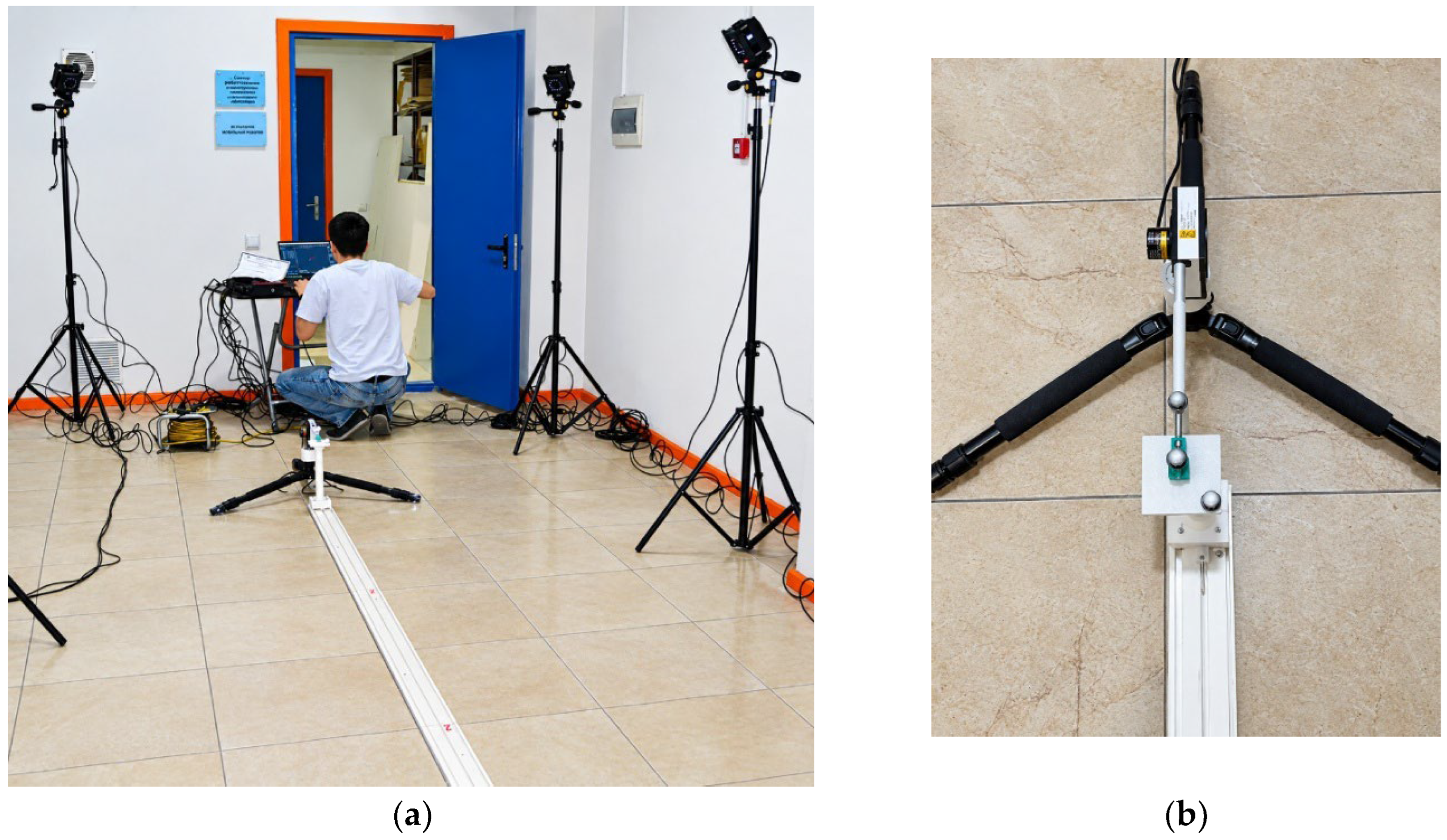
Figure A2.
Sensor verification is performed at points marked on the guide rail at 1-meter intervals.
Figure A2.
Sensor verification is performed at points marked on the guide rail at 1-meter intervals.
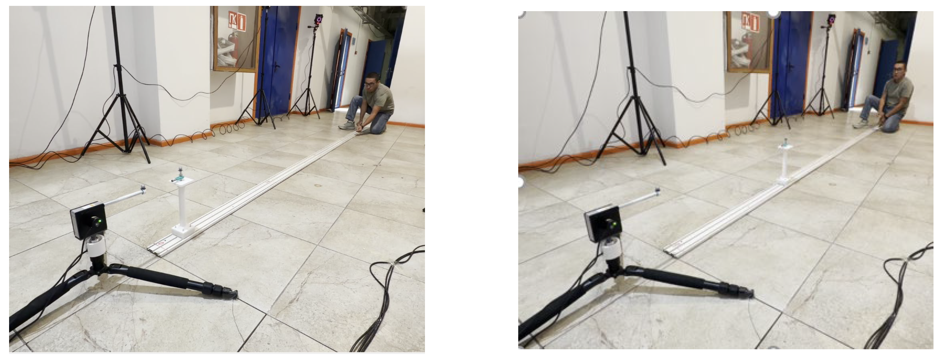
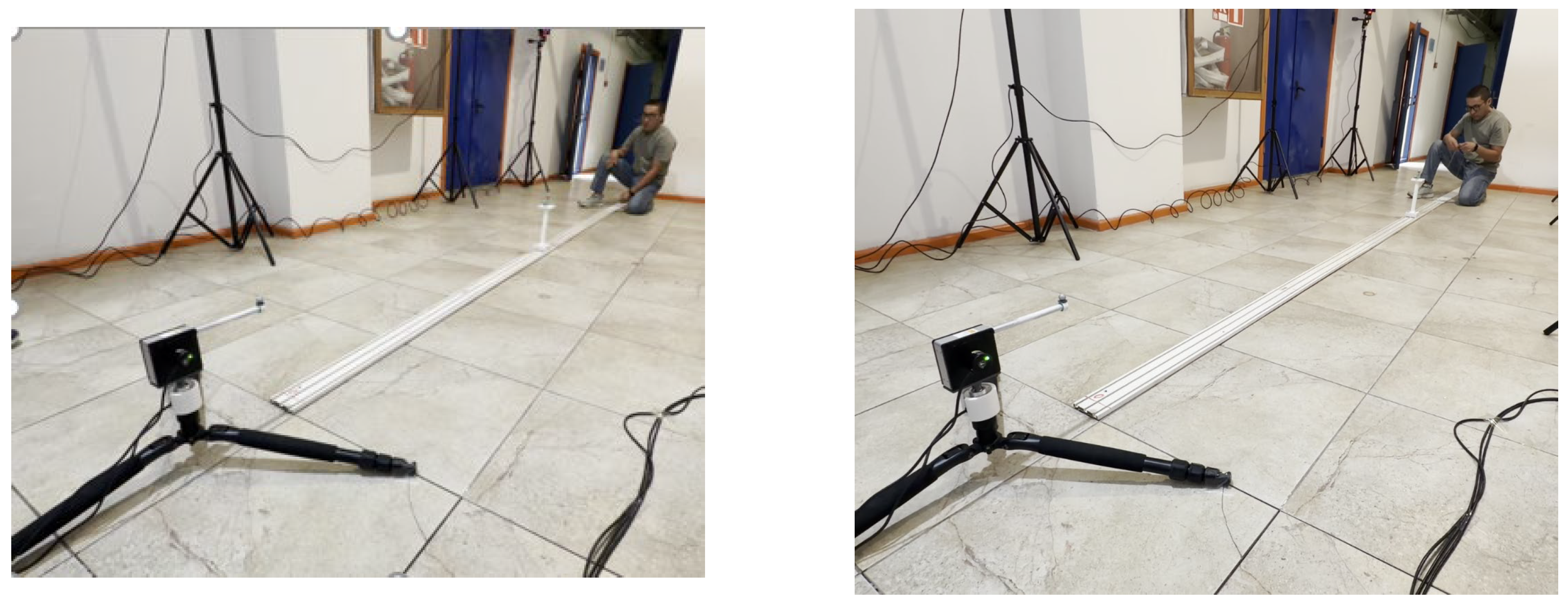
Determine the rope length at the specified points using the OMC NOKOV Lomcand at the sensor itself Lsencor. Calculate the absolute error of the sensor using the formula:
Δ=Lsencor − Lomc
Rope length readings obtained using the OMC NOKOV and the sensor itself, along with the absolute error of the sensor, are presented in Table A1.

Table A1.
Lengths of the rope with OMC NOKOV and the sensor.
| Check point |
Lomc (Reference), mm |
Lsencor (Data), мм |
Δ Absolute error. mm |
| 1000 мм | 1001.64 | 1000.12 | 1.52 |
| 2000 мм | 2002.17 | 2005.11 | 2.94 |
| 3000 мм | 3002.40 | 3005.69 | 3.29 |
| 3000 мм | 4002.48 | 4006.68 | 4.2 |
| 3000 мм | 5002.95 | 5007.54 | 4.59 |
The maximum absolute error of the rope displacement sensor BRT38-5m-C2M4096-RT1, as determined during verification using the OMC NOKOV, is 4.59 mm. According to the specifications provided by Briter Encoder [21], the linear accuracy of the rope displacement sensor BRT38-5m-C2M4096-RT1 is ±0.1%. Given the sensor’s maximum measurement length of 5000 mm, the accuracy is ±5 mm. Verification of the rope displacement sensor BRT38-5m-C2M4096-RT1 using the OMC NOKOV demonstrated good accuracy, falling within the manufacturer’s specified limits.
References
- Klančar, G.; Zdešar, A.; Blažič, S.; Škrjanc, I. Wheeled Mobile Robotics: From Fundamentals towards Autonomous Systems; Butterworth-Heinemann: Oxford, UK, 2017. [Google Scholar]
- Borenstein, J.; Everett, H.R.; Feng, L. Where Am I? Sensors and Methods for Mobile Robot Positioning; University of Michigan: Ann Arbor, MI, USA, 1996. [Google Scholar]
- Borenstein, J.; Feng, L. Measurement and correction of systematic odometry errors in mobile robots. IEEE Trans. Robot. Autom. 1996, 12, 869–880. [Google Scholar] [CrossRef]
- Sousa, R.B.; Petry, M.R.; Moreira, A.P. Evolution of odometry calibration methods for ground mobile robots. In Proceedings of the 2020 IEEE International Conference on Autonomous Robot Systems and Competitions (ICARSC), Ponta Delgada, Portugal, 15–17 April 2020; pp. 294–299. [Google Scholar] [CrossRef]
- Goronzy, G.; Hellbrueck, H. Weighted online calibration for odometry of mobile robots. In Proceedings of the 2017 IEEE International Conference on Communications Workshops (ICC Workshops), Paris, France, 21–25 May 2017; pp. 1036–1042. [Google Scholar] [CrossRef]
- Crowley, J.L. Asynchronous control of orientation and displacement in a robot vehicle. In Proceedings of the 1989 IEEE International Conference on Robotics and Automation, Scottsdale, AZ, USA, 14–19 May 1989; pp. 1277–1282. [Google Scholar] [CrossRef]
- Feng, L.; Koren, Y.; Borenstein, J. Cross-coupling motion controller for mobile robots. IEEE Control Syst. Mag. 1993, 13, 35–43. [Google Scholar] [CrossRef]
- Antonelli, G.; Chiaverini, S.; Fusco, G. A calibration method for odometry of mobile robots based on the least-squares technique: Theory and experimental validation. IEEE Trans. Robot. 2005, 21, 994–1004. [Google Scholar] [CrossRef]
- Martinelli, A.; Siegwart, R. Estimating the odometry error of a mobile robot during navigation. In Proceedings of the European Conference on Mobile Robots (ECMR 2003), Warsaw, Poland, 4–6 September 2003. [Google Scholar]
- Rahok, S.A.; Koichi, O. Odometry correction with localization based on landmarkless magnetic map for navigation system of indoor mobile robot. In Proceedings of the 4th International Conference on Autonomous Robots and Agents (ICARA 2009), Wellington, New Zealand, 10–12 February 2009; pp. 572–577. [Google Scholar] [CrossRef]
- Song, X.; Wang, Y. A novel model-based method for odometry calculation of all-terrain mobile robots. In Proceedings of the 2008 7th World Congress on Intelligent Control and Automation (WCICA 2008), Chongqing, China, 25–27 June 2008; pp. 581–586. [Google Scholar] [CrossRef]
- Nistér, D.; Naroditsky, O.; Bergen, J. Visual odometry for ground vehicle applications. J. Field Robot. 2006, 23, 3–20. [Google Scholar] [CrossRef]
- Marantos, P.; Koveos, Y.; Stergiopoulos, Y.; Panousopoulou, A.; Tzes, A. Mobile robot odometry relying on data fusion from RF and ultrasound measurements in a wireless sensor framework. In Proceedings of the 16th Mediterranean Conference on Control and Automation, Ajaccio, France, 25–27 June 2008; pp. 523–528. [Google Scholar] [CrossRef]
- Papadopoulos, E.; Misailidis, M. On differential drive robot odometry with application to path planning. In Proceedings of the European Control Conference (ECC 2007), Kos, Greece, 2–5 July 2007; pp. 5492–5499. [Google Scholar] [CrossRef]
- Chenavier, F.; Crowley, J.L. Position estimation for a mobile robot using vision and odometry. In Proceedings of the 1992 IEEE International Conference on Robotics and Automation, Nice, France, 12–14 May 1992; pp. 2588–2593. [Google Scholar] [CrossRef]
- Maddahi, Y.; Seddigh, M.; Mohammad Pour, M.; Maleki, M. Simulation study and laboratory results of two-wheeled mobile robot. WSEAS Trans. Syst. 2004, 3, 2807–2812. [Google Scholar]
- Maddahi, Y.; Maddahi, A. YMBM: New method for errors measurements in wheeled mobile robots. WSEAS Trans. Syst. 2006, 5, 552–557. [Google Scholar]
- Maddahi, Y. Design and laboratory tests of wheeled mobile robots. In Proceedings of the International Conference on System Science and Simulation in Engineering, Tenerife, Spain, 16–18 December 2005; pp. 186–191. [Google Scholar]
- Maddahi, Y.; Sepehri, N.; Maddahi, A.; Abdolmohammadi, M. Calibration of wheeled mobile robots with differential drive mechanisms: An experimental approach. Robotica 2012, 30, 1029–1039. [Google Scholar] [CrossRef]
- NOKOV. What Is Motion Capture? Available online: https://ru.nokov.com/about/what-is-motion-capture.html (accessed on 19 September 2026).
- Shenzhen BriterEncoder Technology Co., Ltd. Available online: https://www.briterencoder.com/ (accessed on 19 September 2026).
- Jomartov, A.; Kamal, A. Calibration of Differential Wheeled Mobile Robot with Trajectory Measuring Device. Mendeley Data. 2026, V1. Available online: https://data.mendeley.com/datasets/bp4fhh5zyt/1.
Figure 1.
DWMR scheme.
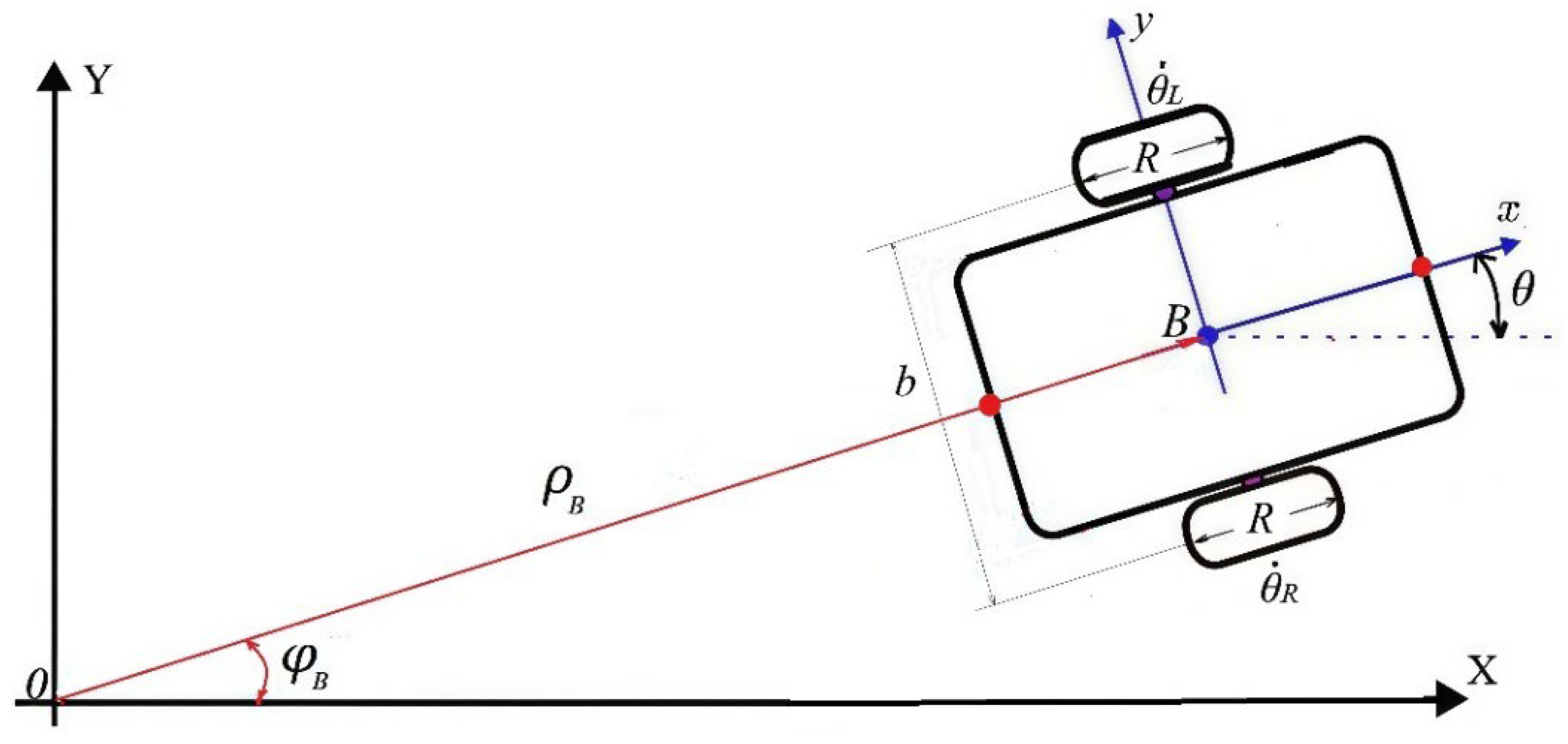
Figure 2.
DWMR motion trajectories [19]: desired path (A), actual path (B).
Figure 2.
DWMR motion trajectories [19]: desired path (A), actual path (B).
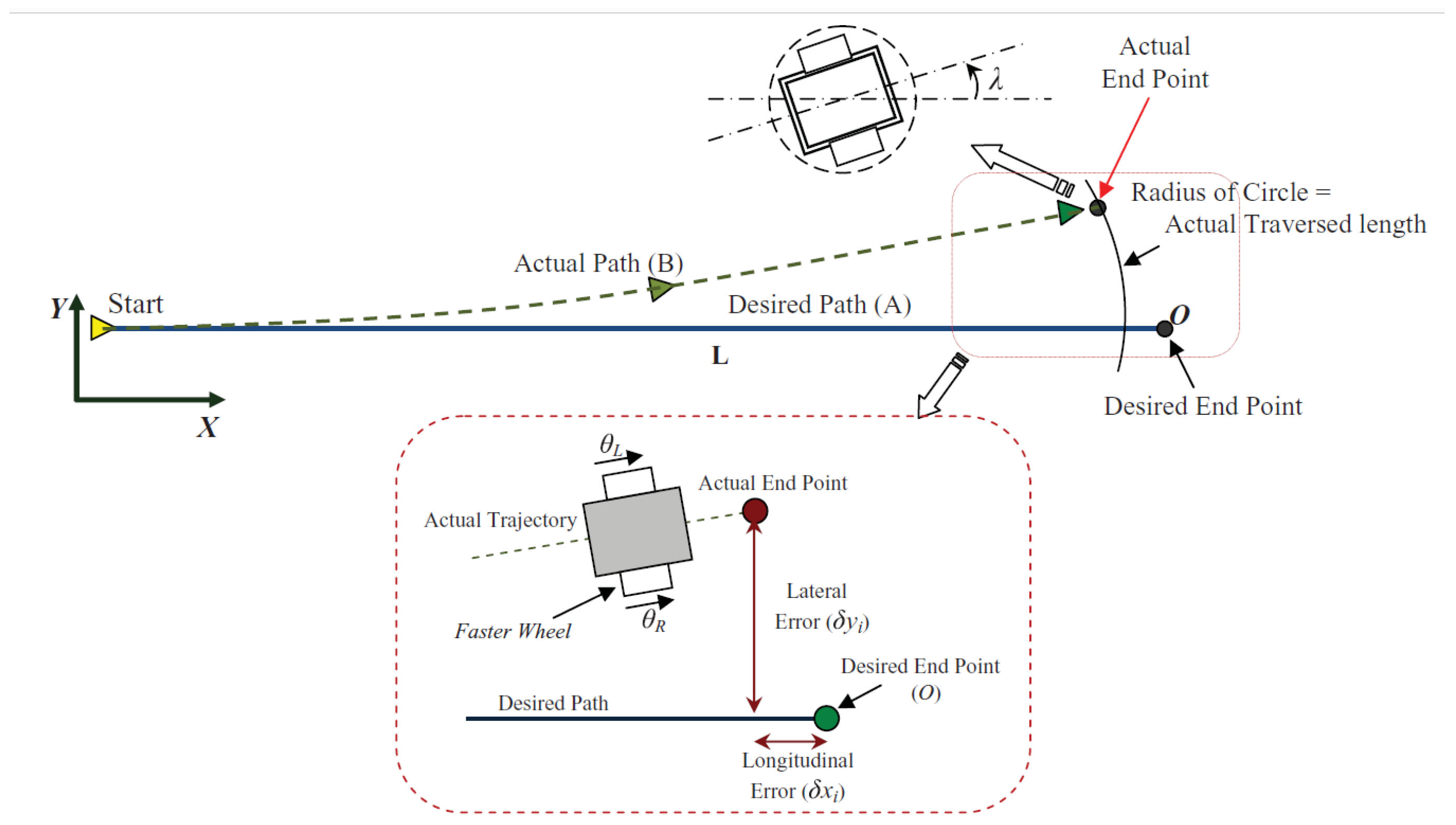
Figure 3.
DWMR trajectory.
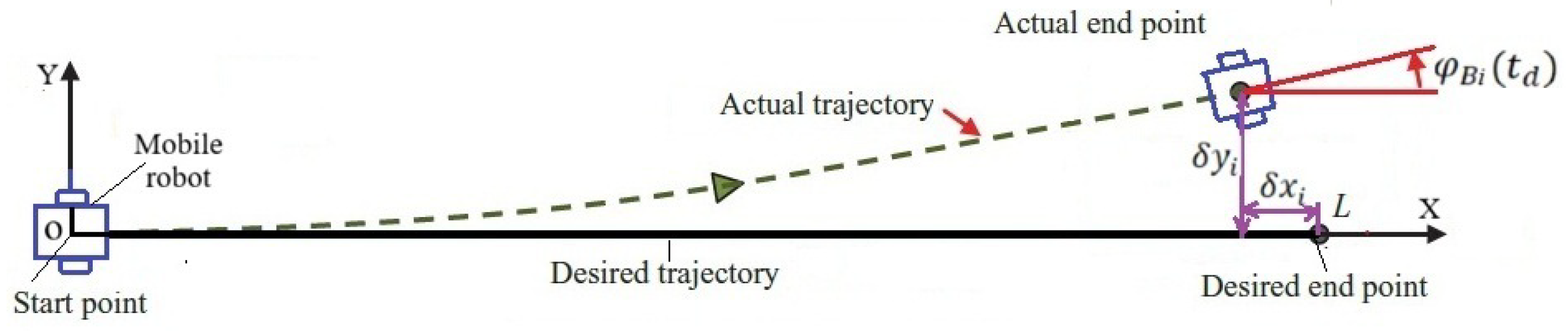
Figure 4.
Sensors: (a) absolute angular encoder, (b) rope displacement sensor.
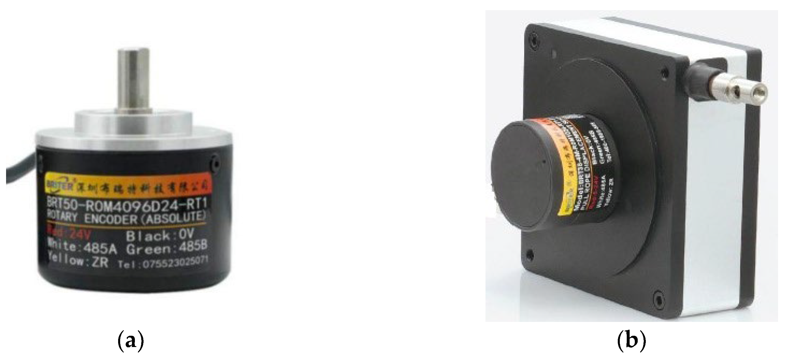
Figure 5.
TMD device.
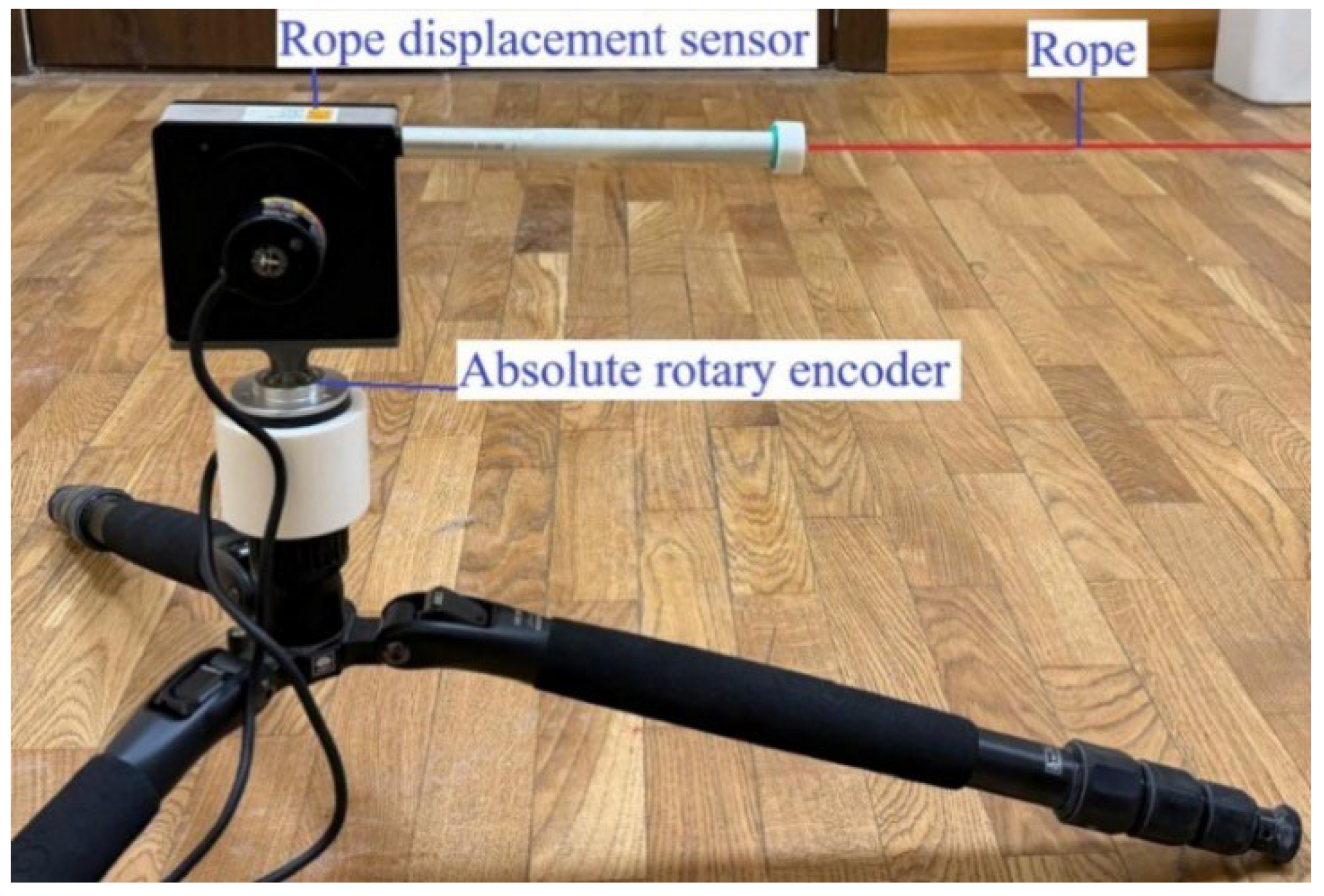
Figure 6.
TMD device connected to DWMR.
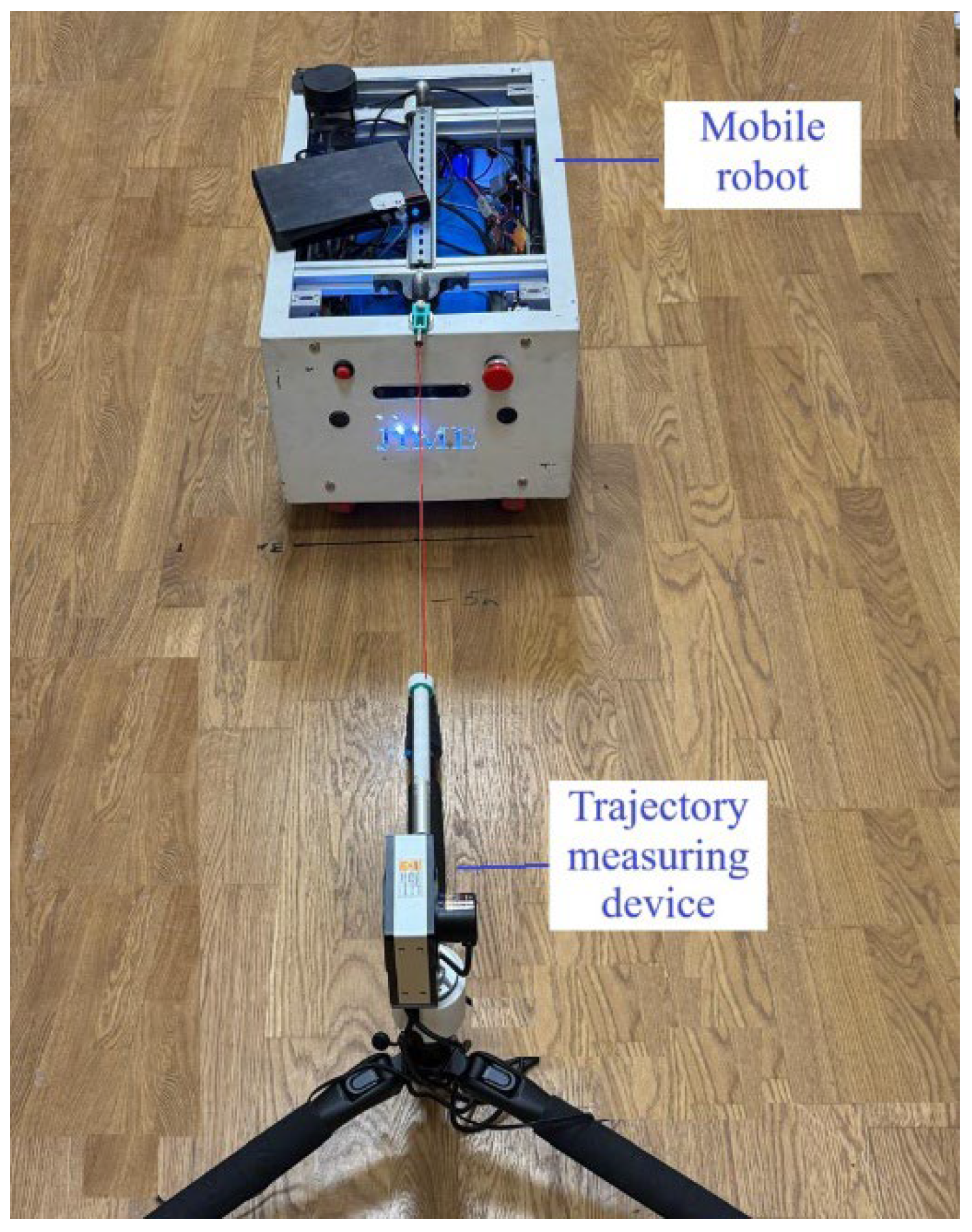
Figure 7.
Experimental graph of the DWMR orientation angle θ = θ(t).
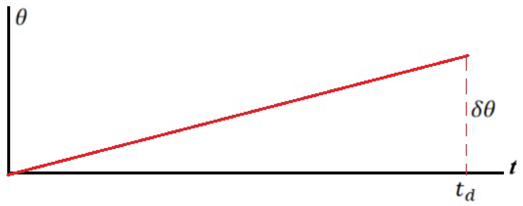
Figure 8.
DWMR MRTC prototype: a) General view, b) Layout of the main components.
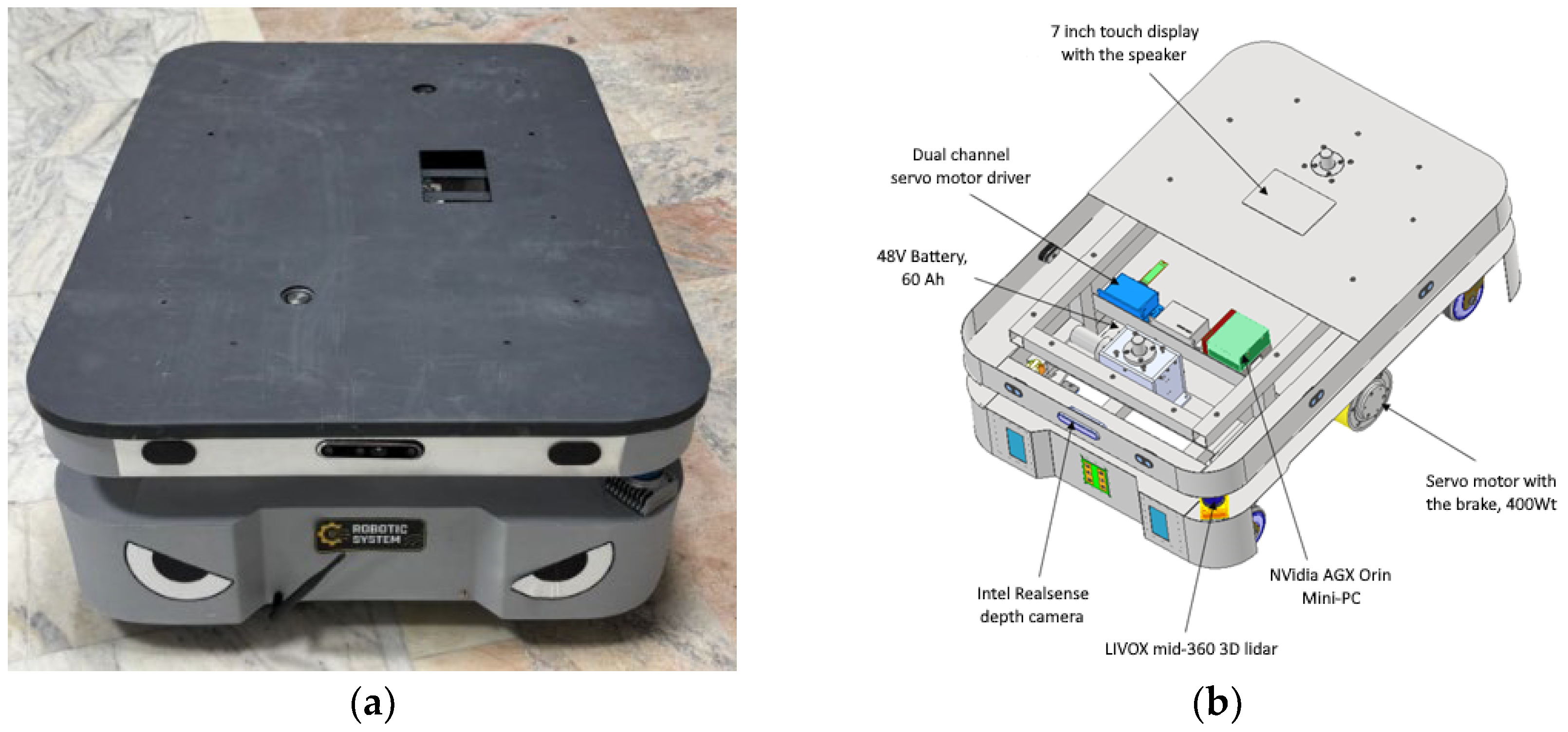
Figure 9.
Experimental studies of the movement of the DWMR MRTC prototype.
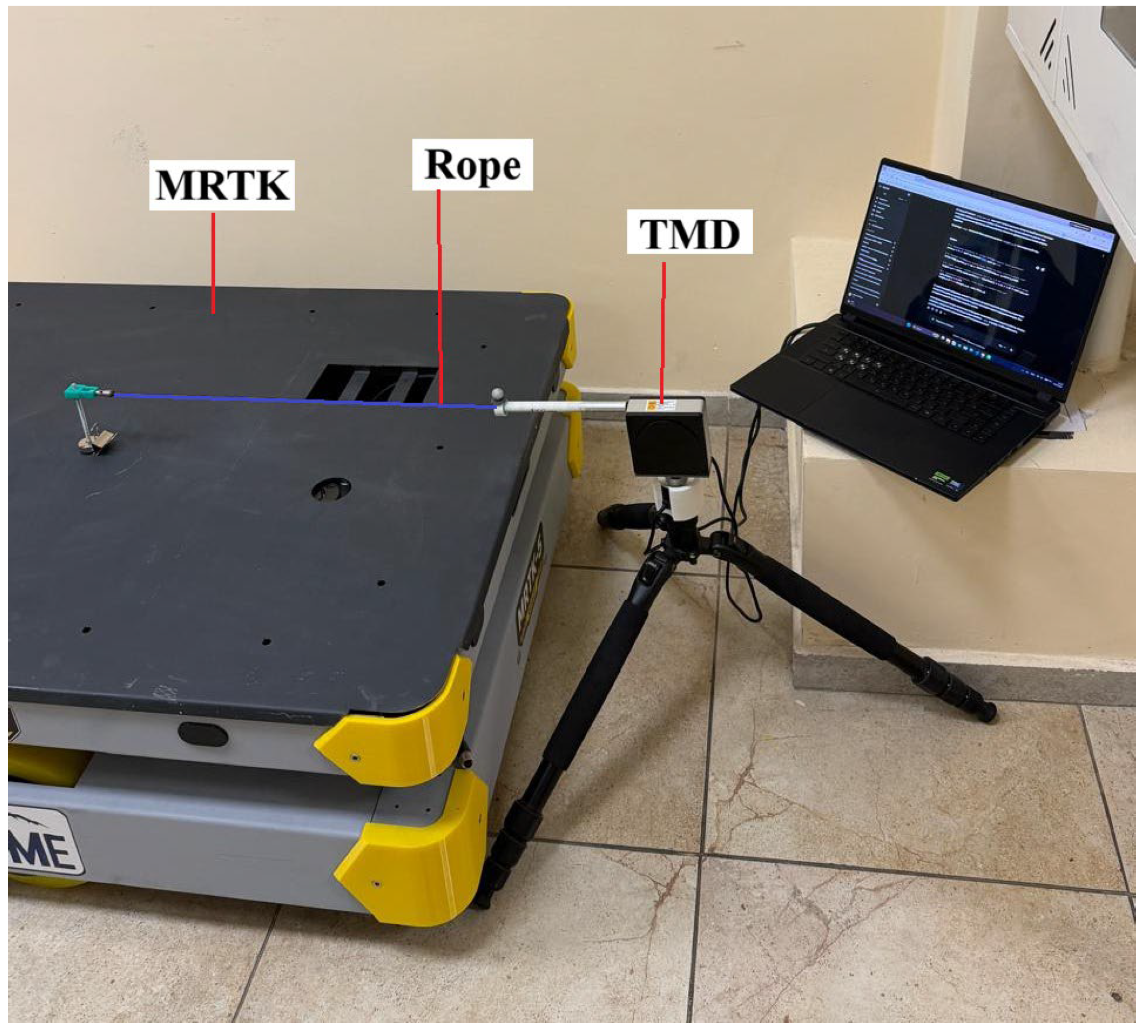
Figure 10.
Graphs of the angular δθi errors of the DWMR MRTC prototype trajectory for the i-th test.
Figure 10.
Graphs of the angular δθi errors of the DWMR MRTC prototype trajectory for the i-th test.
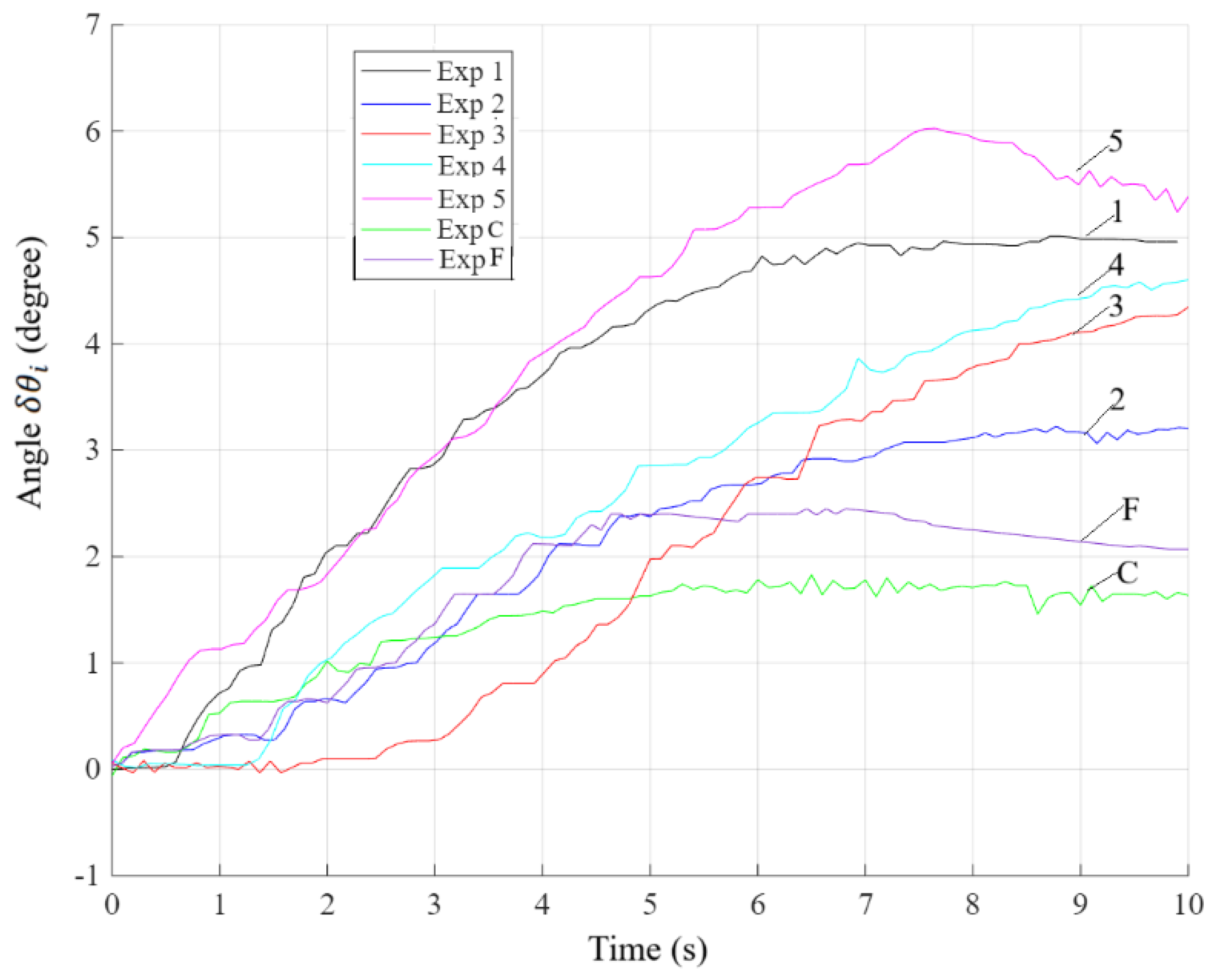
Figure 11.
Graphs of the DWMR MRTC prototype trajectory for the i-th test.
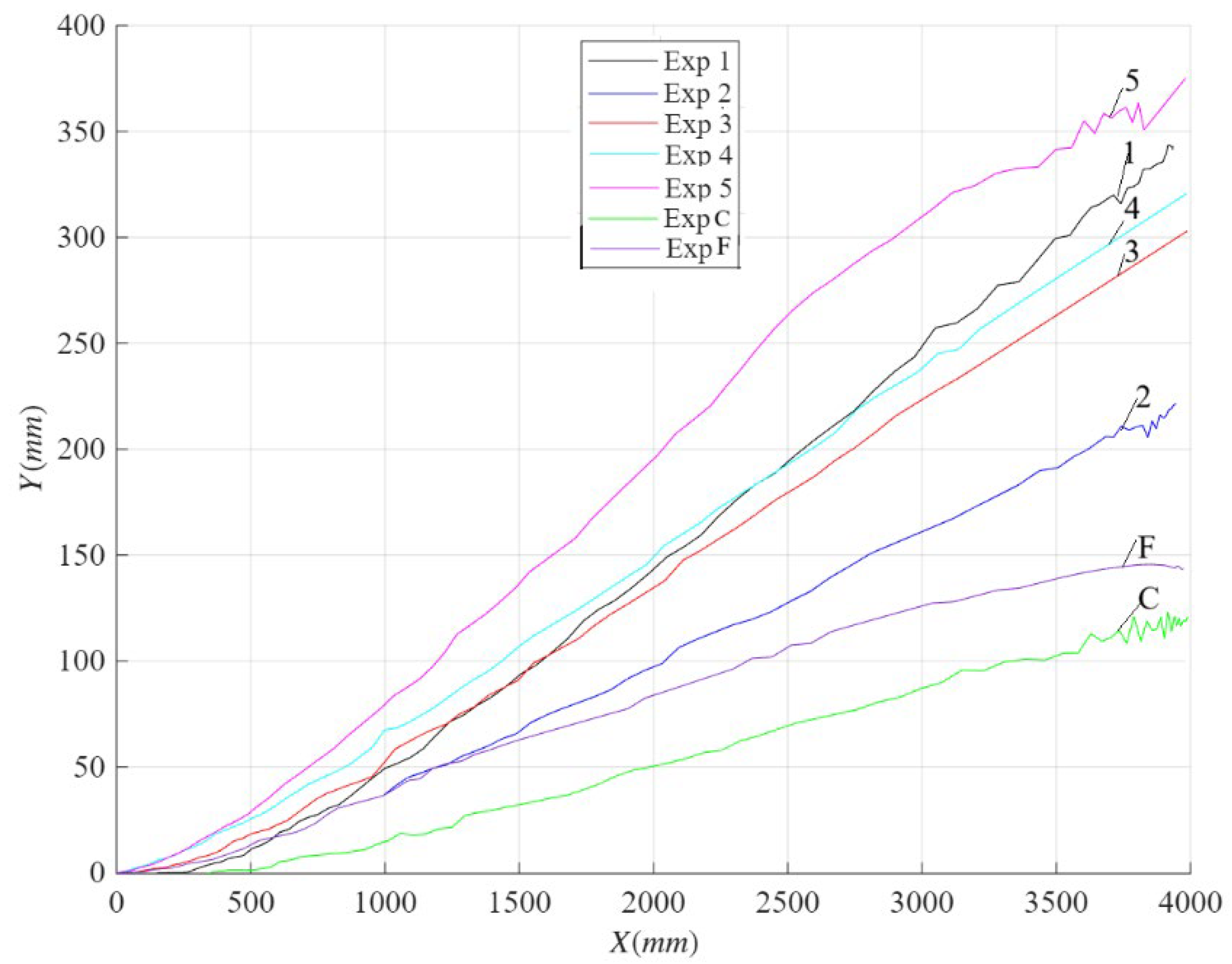
Table 1.
Longitudinal, lateral and angular errors of the DWMR MRTC prototype.
| i | δxi[mm] | δyi[mm] | δθi[degree] |
| 1 | 59 | 240 | 4,96 |
| 2 | 48 | 210 | 3,2 |
| 3 | 102 | 300 | 4,34 |
| 4 | 119 | 320 | 4,6 |
| 5 | 122 | 350 | 5,38 |
Disclaimer/Publisher’s Note: The statements, opinions and data contained in all publications are solely those of the individual author(s) and contributor(s) and not of MDPI and/or the editor(s). MDPI and/or the editor(s) disclaim responsibility for any injury to people or property resulting from any ideas, methods, instructions or products referred to in the content. |
© 2026 by the authors. Licensee MDPI, Basel, Switzerland. This article is an open access article distributed under the terms and conditions of the Creative Commons Attribution (CC BY) license (http://creativecommons.org/licenses/by/4.0/).
Copyright: This open access article is published under a Creative Commons CC BY 4.0 license, which permit the free download, distribution, and reuse, provided that the author and preprint are cited in any reuse.