

Submitted:
30 September 2026
Posted:
01 October 2026
You are already at the latest version
Abstract
This study demonstrates a single-step fabrication of blazed gratings on silicon substrates using direct laser greyscale lithography and aluminum coating. Three key parameters were studied for process optimization, i.e., the exposure dose of the photoresist, the focusing method, and the laser scan writing mode. We have shown that a bijective correspondence between dose and thickness ranging from 0 to 127 mJ/cm2, defined across 100 levels, enabled to obtain a linear photoresist thickness profile. Stitching artifacts were then eliminated using fine optical autofocus with overlap writing mode. Finally, the optimized grating (3.3 µm period, 12° blaze angle, 0.5 µm depth) exhibits a well-defined sawtooth profile, confirmed by atomic force and scanning electron microscopy. Optical characterization using Fourier-plane imaging shows a dominant −1st diffraction order, confirming successful blaze behavior. This work establishes direct laser greyscale lithography as a viable, cost-effective, and fast method for fabricating high-quality blazed gratings.
Keywords:
grating
; laser
; lithography
; blazed
1. Introduction
Blazed diffraction gratings are useful for many spectroscopic applications when high diffraction efficiency is needed since the efficiency of a specific diffraction order can be enhanced by adjusting the grating periodic profile [1]. It is a type of grating that exhibits an asymmetric shape, offering various advantages compared to conventional symmetric gratings, which exhibit diffraction symmetry along the normal axis. For instance, the blaze angle can be designed to obtain a grating whose first diffraction order is enhanced [2], resulting in higher energy efficiency where most of the energy is focused into the desired diffraction order. However, the fabrication is challenging.
Several techniques for blazed grating fabrication have been developed. Mechanical ruling was the first method [3] studied for obtaining large-scale and low-cost blazed gratings but are limited to planar gratings with relatively low roughness and triangular or trapezoidal shapes [4]. Later on, the fabrication of multilayer blazed gratings by consecutively Electron Beam Lithography (EBL) and Reactive Ion Etching (RIE) was proposed [5] but the fabrication requires multiple steps, and the final profile of the grating is a staircase profile instead of a smooth blazed slope. More recently combining both EBL and RIE with tilted sample was developed giving etching under the shadowing effect of the side mask [6,7] but an intrinsic anti-blaze appears. Another method that can be used to fabricate blazed gratings is the Three-Dimensional (3D) printing method by two-photon polymerization. It allows the fabrication of micro and nanostructures with high resolution and small feature sizes, but has the major drawback of an extremely long fabrication time for even the tiniest structures [8]. Finally, Greyscale Lithography (GSL) was also explored. Unlike binary lithography, GSL stands out as superior primarily due to the ability to fabricate planar 3D structures with varying heights and depths which is not possible with binary lithography [9]. However it is limited by the insolation time or the spatial resolution using E-beam [10] or contact mask [11] lithography, respectively. Therefore, these existing methods gave limitations in process complexity, speed, and accurate shape definition.
To overcome drawbacks of previous methods, this study focuses on the use of greyscale mask-less UV laser lithography to develop blazed gratings with micrometre-scale periods, utilising a reduced number of steps and shorter manufacturing times. The primary application of this study is for astronomical instrumentation in ground-based and space telescopes since new high-efficiency spectrographs designed at LAM include convex blazed gratings [6]. Let’s consider typical blazed grating parameters: 300 lines/mm and around 10° blaze angle (i.e 3.3 µm period). For obtaining a grating with such period, three key parameters were optimized: (i) the UV dose, by identifying a range that yields a linear photoresist thickness profile for a bijective (i.e one-to-one correspondence between the grayscale level and the depth of the photoresist) dose gradient; (ii) the focus parameters to achieve the finest laser spot and reduce surface roughness; and (iii) the stitching error compensation using overlapping writing fields. Finally, we characterize devices developed with this optimized process using homemade optical setup confirming that we have a blazed effect in the diffraction. This work aims thus to achieve a highly refined, continuous blazed grating with optimal diffraction efficiency.
2. Materials and Method
Translating the greyscale design into a 3D structure poses multiple challenges. Firstly, the photoresist response to the exposure dose is inherently non-linear. This non-linearity arises from the complex cross-link breaking process under the absorption of photons. Neglecting this effect can lead to the distortion of the intended saw-tooth profile, resulting in curved slopes and reduced diffraction efficiency since it is essential for a blazed grating to have a linear blazed slope for enhancing a specific diffraction order. Furthermore, the control of grating height is also crucial, as changing the grating height can result in different blazed angles. Overall, any deviation in linearity or grating height will result in the degradation of diffraction efficiency and shift of blaze angle, thus the study of the dose-linearity response and dose-depth response of the ma-P 1215G positive photoresist is required.
The overall fabrication process is schematically illustrated in Figure 1(a), which consists of four main steps: the substrate was first spin-coated with a photoresist, followed by the direct laser exposure, and by the development step to remove the exposed area. Finally, a metal layer was coated to obtain high reflectivity. To perform the direct writing lithography process, a Two-Dimensional (2D) digital design is required using bitmap file. The design has a resolution of 200 nm/pixel; in other words, one pixel in the design file corresponds to a 200 nm feature size in the fabricated structure. The 2D blazed grating design was generated in Python by mapping the greyscale value of each pixel to a sawtooth function along the x-direction, with a constant value along the y-direction. Figure 1(b) shows the 2D greyscale, and Figure 1(c) presents the corresponding cross-sectional greyscale level profile along x, which is the laser sweep direction. One hundred greyscale levels were used for the design to ensure compatibility with the laser writer’s hardware limitations, which in this study was the Heidelberg µPG 101 laser writer [12]. Greyscale value exceeding the maximum supported level of the laser writer are automatically assigned to the maximum dose, which causes dose saturation according to experimental tests (data not shown).
To prepare the sample, Si wafers were diced into squares of 2 x 2 cm2, rinsed with acetone and deionized water, and dried with compressed N2 gas. Positive photoresist ma-P 1215G was chosen due to its high suitability for greyscale lithography. The resist was spin-coated at 3000 rpm for 30 s to obtain a layer of 1.5 µm according to the datasheet, followed by pre-baking at 105oC for 2 min. A Heidelberg µPG101 tabletop mask-less laser lithography system operated at 405 nm with a 900 nm spot diameter was used for GSL [12]. The laser beam was focused using both pneumatic auto-focus and manual optical auto-focus. The optimization of focus will be discussed in the following. Samples were exposed with different laser powers ranging from 0.5 to 2.5 mW further reduced by use of a filter with ~10% transmission and a writing speed of 5 mm2/minute [12]. By assuming a laser sweep speed of 10 cm/s, we evaluated the insolation dose at around 127 mJ/cm2 for 1 mW power (by assuming no overlap between the different sweeps). The exposed samples were then developed with ma-D 532/S aqueous solution for 45 s and then rinsed with deionized water.
To perform metallization of the grating for diffraction pattern measurements, an Alliance Concept AC450 DC/RF sputtering system was used to deposit thin films of 5 nm Cr as an adhesion layer and 125 nm of aluminum, respectively. Flex-Nanosurf Atomic Force Microscopy (AFM) and MIRA TESCAN Scanning Electron Microscopy (SEM) were used for the morphological evaluation of the grating structure. For optical characterization, a homemade set-up was used [13]. Laser excitation was focused at normal incidence with a given wavelength through an objective (20x magnification and 0.45 numerical aperture), the reflected diffracted orders were collected with the same objective and a beam splitter. An auxiliary converging lens was used for measuring the Fourier plane on the camera giving directly an image in the reciprocal space.
3. Result and Discussion
3.1. Dose Influence
A batch of exposures at different doses with 20% of the energy filtered out was performed to investigate the effect of the doses and the photoresist response for greyscale levels ranging from 0 to 100 over a 100 µm length Figure 2(a) presents the measured side profiles for five laser powers (0.5, 1.0, 1.5, 2.0, and 2.5 mW): the higher the dose, the further the curve deviates from a linear profile (represented by dash lines on the graph).
As observed in Figure 2(a), at low exposure doses the profiles exhibit excellent linearity, with the depth increasing proportionally with the dose. This indicates that within this low-energy regime, the photoresist polymer chains undergo a predictable scission process, and the dissolution rate during development is directly proportional to the deposited energy. However, as the laser power increases beyond 1.0 mW (corresponding to 127 mJ/cm2), a clear non-linear behavior is observed. The profiles become progressively more curved, with the slope changing non-uniformly across the grating period. Based on these observations, the effective laser power chosen for later experiments of this study was 1 mW, as this power gave a linear profile and a suitable depth of ~500 nm for the fabrication of grating.
The depth of the structures is plotted as a function of the grayscale-weighted laser intensity in Figure 2(b). The superimposition of the curves obtained for laser powers ranging from 1 mW to 2.5 mW confirms a bijective relationship between the gray levels and the dose fractions. The deviation from this curve behavior at a laser intensity of 0.5 mW is potentially due to poor calibration of the laser at low level, which represents only 0.7% of its maximum power.
A diffraction grating with a 3.3 µm period was then fabricated over a 1 cm2 surface with the laser set at 1 mW. The surface scan and the extracted profile can be seen in Figure 3(a) and Figure 3(b), respectively. The standard deviation of the depth and period have been evaluated to be below 5% over the whole sample.
3.2. Focus and Overlap Optimization
The quality and performance of the blazed grating are not only determined by the linearity and the blaze angle, but also by the structure resolution of the grating, which directly depends on the focus condition of the laser beam. A poorly focused beam results in a broader spot, causing the proximity effect where the exposure at one position affects its surrounding positions, leading to blurred structures and reduce the edge sharpness. In order to improve the spatial resolution (and also to reduce the anti-blaze slope), we switched from pneumatic focus to optical focus modes. This more accurate focusing avoids side effects and enables the achievement of the smallest laser spot size, estimated at 900 nm in diameter according to the laser writer datasheet [12]
Figure 4(a) and Figure 4(b) present AFM scans of gratings fabricated with low-focus (pneumatic) and fine-focus (manual optical) modes, respectively. The improvement is striking: the fine-focus sample shows significantly, sharper edges, and a much smaller anti-blaze angle. However, with the more refined beam spot, the stitching-artifacts are more visible. Indeed, in the pneumatic-focus samples, stitching artifacts were not clearly visible because the defocused beam (larger spot size) effectively blurred the boundaries through the proximity effect. However, when we switched to the optical autofocus mode with its finer beam spot, stitching artifacts became clearly apparent as periodic discontinuities at the seam between adjacent writing fields (Figure 4b) since the distance between the laser sweep periods is around 1.2 µm along the y-axis.
These artifacts are particularly problematic because they introduce localized variations in the blaze angle and depth, which can scatter light into unwanted diffraction orders. To mitigate these artifacts, we implemented a “four-time” overlapping where the exposure dose and the step distance between two doses were reduced by four. “Four-time” overlap means that the distance between two laser sweeps is reduced by four giving 0.3µm distance between the insolated line like indicated in Figure 4-c. By reducing both the energy and the step, the total amount of exposure is unchanged, with the overlapping smoothing the mismatching artifacts without causing excessive crosslink breaking. This approach effectively compensates for both dose mismatches and small positioning errors. The result, shown in Figure 4(c) exhibits no visible discontinuities at the field boundaries, confirming the effectiveness of the blending strategy.
3.3. Optical Characterization
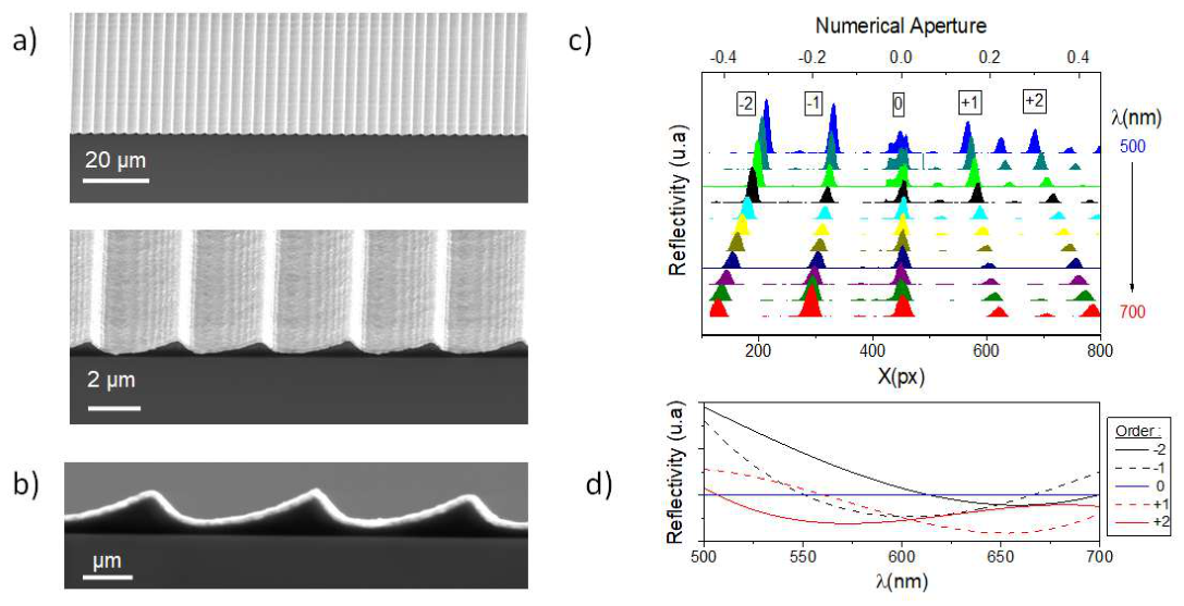
Following the optimized fabrication parameters mentioned previously (1.0 mW with filter ON, optical autofocus, and a factor of four times overlapping), we fabricated the final blazed grating for structural and optical evaluation. Figure 5(a) and Figure 5(b) present SEM images of the grating with tilt angles of 45° and 90° (cross-section), respectively. The SEM images confirm a well-defined, periodic sawtooth structure with a period of 3.3 µm. The sidewalls are sharp with a blazed slope that is slightly curved and with small anti-blaze angles. Analysis of the SEM side-profile images gives a grating height of approximately 530 nm, a blaze angle of 12°. The anti-blaze region measure 1.1µm which correspond well to the convolution of a Gaussian with 900nm FYHM (corresponding to the laser spot) with the saw tooth function presented in Figure 1-c. The observed stair effect is potentially attributed to interferences in the photoresist during the insolation, which would be addressed in further development by using an anti-reflection layer.
The optical performance of the grating was characterized using the Fourier-plane imaging setup described in the experimental setup section. A series of laser beams with wavelength ranging from 500 nm to 700 nm with a step size of 20 nm was directed at normal incidence onto the grating surface. The reflectivity normalized by the zero diffraction order and a silver mirror shows distinct diffraction peaks corresponding to the -2nd , -1st , 0th, 1st, 2nd orders. Reflectivity as a function of the wavelength for the different order is plotted on the Figure 5-d. Upon detailed speculation of the 700 nm wavelength, where the −1st order exhibits the highest intensity within the wavelength band, it can be seen that the -1st order is much stronger than the +1st order. This asymmetry, where the −1st order dominates over the +1st order, is characteristic of an over-blazed grating, where the blaze angle measured as 16° is larger than the optimal value for the incident wavelength since the optimal blaze angle for a 700 nm beam, calculated from the grating equation mλ = 2dsin(θB), is ≈ 6.1. The presence of a non-negligible 0th order and the significant intensity of the −2nd order indicate that a portion of the incident energy is distributed to the higher diffraction order, rather than being fully concentrated into the first order. This can be attributed to the remaining minor defects of the fabricated grating even after the optimization of the fabrication process. Nevertheless, the optical characterization at 700 nm wavelength provides clear evidence that the fabricated grating exhibits blaze-like behavior, with the −1st order being the most intense and the 0th order significantly attenuated compared to a simple reflective surface.
4. Conclusion
In this study, we have successfully demonstrated the fabrication of blazed gratings using direct laser greyscale lithography on silicon substrates, obtaining continuous saw tooth profile with a period of 3.3 µm and a measured blaze angle of approximately 12°. Three key challenges of the GSL process were investigated and addressed. A bijective dose gradient ranging from 0 to 127 mJ/cm2 with 100 steps provides linear smooth depth-dose behaviour with a developed depth of ~700 nm. Secondly, a comparison of pneumatic and optical autofocus modes revealed that optical autofocus significantly improves structural quality. AFM measurements showed that optical focus reduces edge curviness while showing the stitching artefacts caused by dose mismatch. A four-time overlapping strategy was shown to be effective in removing those artefacts and further reducing surface roughness, ensuring seamless continuity across writing field boundaries but at the cost of increased writing time. Optical characterization using Fourier-plane imaging over the spectrum from 500 to 700 nm revealed a dominant −1st diffraction order, confirming that the grating successfully concentrated energy in the desired direction. These results establish direct laser greyscale lithography as a single-process and fast alternative for fabricating high-performance blazed gratings. Such development allows to envision next generation of high efficiency spectrograph devoted to astronomy (primary application), physics and biology research fields.
Data Availability Statement
The raw data supporting the conclusions of this article will be made available by the authors on request.
Acknowledgments
The authors would like to thank the NanoLyon platforms member of the CNRS-RENATECH+ French national network and the “Laboratoire d’Astrophysique de Marseille” for the internship funding.
References
- Loewen, E.G.; Nevière, M.; Maystre, D. Grating efficiency theory as it applies to blazed and holographic gratings. Appl. Opt. 1977. [Google Scholar] [CrossRef] [PubMed]
- Ans, S.; Zamkotsian, F.; Demésy, G.; Mursa, A.; Salut, R.; Passilly, N. Nanostructured blazed gratings for high-efficiency spectrographs by topology optimization. 2025. [Google Scholar] [CrossRef]
- Wood, R.W. The echelette grating for the infra-red. J. Franklin Inst. 1911. [Google Scholar] [CrossRef]
- Gao, J.; Chen, P.; Wu, L.; Yu, B.; Qian, L. A review on fabrication of blazed gratings. J. Phys. D. Appl. Phys. 2021, 54. [Google Scholar] [CrossRef]
- Oliva, M.; Harzendorf, T.; Michaelis, D.; Zeitner, U.D.; Tünnermann, A. Multilevel blazed gratings in resonance domain: an alternative to the classical fabrication approach. Opt. Express. 2011. [Google Scholar] [CrossRef] [PubMed]
- Zamkotsian, F.; Ilbert, O.; Zoubian, J.; Delsanti, A.; Boissier, S.; Lancon, A. BATMAN FLIES: A COMPACT SPECTRO-IMAGER FOR SPACE OBSERVATION. Proc. SPIE. 2014, 10563, 1–9. [Google Scholar] [CrossRef]
- Wang, Y.; Pan, A.; Zhu, X.; Cui, B. Fabrication of blazed gratings by tilted reactive ion beam etching with the side mask for augmented reality applications. J. Vac. Sci. Technol. B. 2024. [Google Scholar] [CrossRef]
- Zhou, X.; Hou, Y.; Lin, J. A review on the processing accuracy of two-photon polymerization. AIP Adv. 2015. [Google Scholar] [CrossRef]
- Khonina, S.N.; Kazanskiy, N.L.; Butt, M.A. Grayscale Lithography and a Brief Introduction to Other Widely Used Lithographic Methods: A State-of-the-Art Review. Micromachines 2024. [Google Scholar] [CrossRef] [PubMed]
- Liu, L.; Zhang, X.; Zhu, J.; Dong, S.; Wei, Z.; Wang, Z.; Cheng, X. Optimizing and well-Controlled Grayscale Electron Beam lithography for planar dual-blazed grating fabrication. Vacuum 2025. [Google Scholar] [CrossRef]
- Mouroulis, P.; Hartley, F.; Wilson, D.; White, V.; Shori, A.; Nguyen, S.; Zhang, M.; Feldman, M. Blazed grating fabrication through gray-scale Xray lithography. Opt. Express. 2003, 11. [Google Scholar] [CrossRef] [PubMed]
- Heidelberg UPG101 laser writer Datasheet (n.d.). Available online: https://www.nanofab.utah.edu/wp-content/uploads/2022/12/uPG101-UG3-User-Manual-Rev7.pdf (accessed on 17 August 2026).
- Guebrou, S.A.; Symonds, C.; Homeyer, E.; Plenet, J.C.; Gartstein, Y.N.; Agranovich, V.M.; Bellessa, J. Coherent Emission from a Disordered Organic Semiconductor Induced by Strong Coupling with Surface Plasmons. Phys. Rev. Lett. 2012, 066401, 1–5. [Google Scholar] [CrossRef] [PubMed]
Figure 1.
(a) Schematic of greyscale lithography process for blazed grating fabrication; (b) greyscale design for grating with period of 3.3 µm and (c) 1D pattern of the blazed grating along x-direction with total 100 greyscale levels.
Figure 1.
(a) Schematic of greyscale lithography process for blazed grating fabrication; (b) greyscale design for grating with period of 3.3 µm and (c) 1D pattern of the blazed grating along x-direction with total 100 greyscale levels.
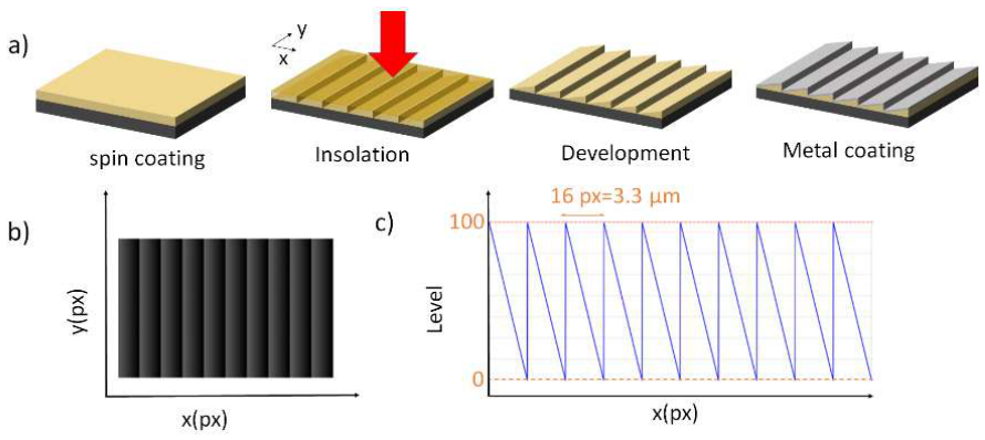
Figure 2.
(a) Different laser doses versus depth profile and (b) Laser intensity versus depth of ma-P 1215G photoresist.
Figure 2.
(a) Different laser doses versus depth profile and (b) Laser intensity versus depth of ma-P 1215G photoresist.
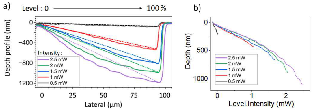
Figure 3.
(a) 20x20µm2 AFM scan and (b) extracted profile of fabricated grating at 1 mW laser without focus optimization.
Figure 3.
(a) 20x20µm2 AFM scan and (b) extracted profile of fabricated grating at 1 mW laser without focus optimization.

Figure 4.
AFM scan of blazed grating fabricated using (a) low laser focus; (b) fine laser focus and (c) fine focus laser with over-lapping.
Figure 4.
AFM scan of blazed grating fabricated using (a) low laser focus; (b) fine laser focus and (c) fine focus laser with over-lapping.
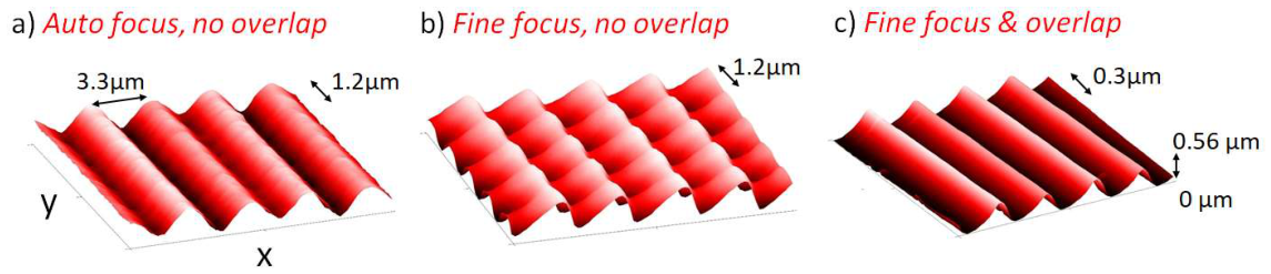
Figure 5.
Scanning Electron Microscopy (SEM) image of blazed grating for (a) tilted sample and (b) cross section; (c) Normalized reflectivity for different diffraction orders of the blazed grating.
Figure 5.
Scanning Electron Microscopy (SEM) image of blazed grating for (a) tilted sample and (b) cross section; (c) Normalized reflectivity for different diffraction orders of the blazed grating.
Disclaimer/Publisher’s Note: The statements, opinions and data contained in all publications are solely those of the individual author(s) and contributor(s) and not of MDPI and/or the editor(s). MDPI and/or the editor(s) disclaim responsibility for any injury to people or property resulting from any ideas, methods, instructions or products referred to in the content. |
© 2026 by the authors. Licensee MDPI, Basel, Switzerland. This article is an open access article distributed under the terms and conditions of the Creative Commons Attribution (CC BY) license (http://creativecommons.org/licenses/by/4.0/).
Copyright: This open access article is published under a Creative Commons CC BY 4.0 license, which permit the free download, distribution, and reuse, provided that the author and preprint are cited in any reuse.