
Submitted:
23 September 2026
Posted:
24 September 2026
You are already at the latest version
Abstract
Small-scale molten salt fast reactor (MSFR) demonstrators are essential for validating reactor physics, fuel cycle integration, and operational characteristics of liquid-fuel fast reactors. However, unlike large commercial MSFR concepts designed for near iso-breeding operation, demonstrators typically exhibit burner behaviour, resulting in a continuous loss of reactivity during operation. This creates a major challenge for concepts aiming to operate without a conventional mechanical control system. To address this issue, we propose and evaluate an innovative stainless-steel sleeve using the HELIOS-based neutronic modelling framework developed for molten salt reactor studies.
The sleeve is a stainless steel reflector inserted inside the core vessel, where it simultaneously improves neutron reflection and provides a reserve of fuel volume that can be released gradually by reducing sleeve thickness during operation and increasing the fuel inventory without additional fuel salt. Parametric studies show that an optimised sleeve thickness of approximately 24 cm reduces the critical fuel inventory by about 30%, a massive upfront cost benefit, while maintaining the same initial criticality. Stepwise reductions of sleeve thickness provide up to 3500 pcm of reactivity compensation, exceeding the approximately 1600 pcm reactivity loss expected during the planned 20-year operating period.
Beyond reactivity management, the sleeve significantly decreases fast neutron exposure of the reactor vessel. Lifetime neutron fluence is reduced to roughly 25% of the reference case for neutrons above 100 keV and to about 7% for neutrons above 1 MeV. The concept therefore combines passive reactivity compensation, reduced fuel requirements, and enhanced vessel protection. Results indicate that the sleeve offers a promising pathway toward long-term operation of a small-scale molten salt fast reactor demonstrator without reliance on a mechanical control system.
Keywords:
nuclear
; nuclear energy
; molten salt reactor
; fast reactor
; demonstration
; technology transfer
; burnup
; reactivity compensation
1. Introduction
The transition toward low-carbon energy systems has renewed strategic interest in nuclear power as a reliable, scalable, and continuously available component of global decarbonisation strategies, with current goals aiming to triple or quadruple nuclear capacity worldwide [1,2,3]. Advanced reactor systems, particularly the Molten Salt Fast Reactor (MSFR), could be central to this expansion due to their potential to improve resource utilisation [4,5] and ideally the significantly reduced long-lived radioactive waste in parallel, as described in the iMAGINE framework [4,7]. Despite these potential advantages, a critical gap remains in the limited operational experience with molten salt fast reactors, as current understanding is derived primarily from modelling studies [8,9] and a small number of historical experimental programmes [10,11,12].
To bridge the gap between concept development and commercial deployment, a small-scale demonstrator (DEMO) is required to mature the technology by validating reactor physics, safety characteristics and fuel-cycle integration under realistic operating conditions, as well as accumulating operational experience [7,13]. There exists a wealth of experience in demonstration through historical demonstrators leading the development of other reactor types such as EBR-II [14] and AVR [15] which provided valuable operational experience. More recent concepts such as MOSART focus on experimental verification of molten-salt chemistry and fuel-cycle processes [16] resolving and demonstrating as many of the discussed challenge areas [17] as possible, as well as the accumulation of operational experience in a demonstrator under construction [9]. However, looking into the challenges of iMAGINE, the design of a comprehensive small-scale (DEMO) for a system later delivering on a closed fuel cycle without prior reprocessing and on waste burning introduces a fundamental “design dilemma”: whereas large-scale MSFR concepts like iMAGINE are intended to operate as iso-breeders, small-scale demonstrators such as DEMO inherently behave as burners [18]. As a result, maintaining criticality becomes significantly more challenging because the limited breeding capability cannot fully compensate for the continuous depletion of fissile material during operation. A strong control system represents one of the most challenging problems in fast-reactor safety, since mechanical control-system malfunctions are recognised as significant accident initiators [19,20], thus there is a tendency to limit the power of the control system by reducing the reactivity swing within the core during an operational cycle in solid-fuelled reactors [20,21].
We have considered even more far-achieving objective for DEMO , it is to demonstrate stable operation of a molten salt reactor without a traditional mechanical control system, with the intention that this design philosophy can subsequently be transferred to future large-scale iso-breeder reactors [18,22]. Previous investigations into non-mechanical compensation strategies, including fissile over-feeding, exploitation of negative thermal feedback effects, and online salt clean-up, have demonstrated that no single approach is entirely satisfactory, as each is associated with some strong technical, operational, or economic trade-offs [18].
We need innovation to overcome this challenge. Based on the model, simulations, and insights provided in [18], a new approach is investigated and discussed in this publication. The study is approached by starting with a reference case based on the preferred case of [18] for comparison. The new approach is to insert an additional stainless-steel reflector (sleeve) into the core vessel to improve reflection, as well as allowing changes in the available fuel volume by varying the thickness of the reflector through replacement. After a first efficiency test starting with a reference case based on the preferred case of [18], a detailed optimisation is performed to achieve the greatest possible fuel saving. The study will be concluded with evaluating the effects of the sleeve on the fast neutron fluence on the vessel and a discussion of the pros and cons of the sleeve.
2. Model, Code and Data
The codes and methods description have already been provided in several publications [18,23,24,25] and others. However, it is adapted to the specifics of this study, and it is essential for general understanding. The HELIOS code system version 2.03 with the internal 173 group library [26] has been employed. HELIOS is a 2D spectral code with wide unstructured mesh capabilities and a transport solver based on the collision probability method [27] and the Method of Characteristics [28]. The general model is based on the EVOL benchmark configuration [29], which is transferred to a volume-corrected 2D HELIOS model see [1,24,25] and others, but reduced to two loops for DEMO (see Figure 1). The model and its related discretisation of the fuel regions are parametrised within the AURORA input, which is within the code process to provide the specific HELIOS input. This allows changes in the core size by just changing one single parameter, which proportionally adapts the inner core size as well as all related discretisation and the outer fuel regions representing the cycles with the pumps and the heat exchangers, while the vessel and reflector dimensions are kept constant. The leakage in the third dimension is introduced into the calculation through the insertion of a buckling correction available in HELIOS (BSQ), as defined in [18], which is kept constant through this study since no changes in the third dimension are investigated.
The salt system chosen for iMAGINE, and thus the basis for DEMO, is based on NaCl-UCl3-UCl4 with the eutectic composition 42.5%–17.0%–40.5%. A detailed discussion of the data of the salt system and the rationale behind the choice is given in [31]. The blanket area of EVOL is replaced by stainless steel as a reflector, while the B4C protector is kept. The reference core model diameter (inner core size) is 180 cm, but it is later adapted. U-235 enrichment is limited to a maximum of 19.9%, the Cl-37 enrichment is set to 99% and the operational temperature to 980K.
The operational schedule follows [18] plan (1 MW for 3 years, 10 MW for 3 years and later 50 MW for the remaining 14 years)
The HELIOS code is an industrial-standard software which is designed to perform neutron transport calculations, burnup calculations, and if requested, cross-section preparation for core simulators. Originally, the HELIOS code was written for the simulation of solid-structured fuel assemblies; thus the possibility of online refuelling, online reprocessing, and the release of fission gas and volatiles from the core was not foreseen. To deal with these special features required for the simulation of molten salt reactor operation, a PYTHON script has been developed [24], which is based on the special features of the HELIOS package.
All input data, which does not change during the whole reactor operation, is stored in a so-called expert input. The changing material configuration is fed into the system through a user input which is rewritten in every cycle using a PYTHON script. Within each of the cycles, 5 burnup steps are run within the HELIOS calculations. The expert input and the updated user input are merged in the pre-processor AURORA [32] in every cycle to create the input for the HELIOS run, delivering the neutron flux distribution and the burnup. The results are evaluated in the post-processor ZENITH [33]. On the one hand, here it is decided which elements are reduced or increased and to what extent and on the other hand, the data for the new user input is created in ZENITH using the information to be fed back into the next cycle by the PYTHON script (see Figure 2). Theoretically, it would be possible to simulate a molten salt reactor to high precision by using small time steps in this loop.
In a real MSR, two different time scales for the salt cleanup will take place based on two different processes: the release of gaseous and volatile fission products with a comparably short acting time and the online salt cleanup for the dissolved fission products with a significantly longer acting time, with both processes having their own efficiency. The cycle time for each power regime is kept constant through the adopted burnup steps. The cycle length decides the full removal of gaseous and volatile fission products (the elements 18, 35, 36, 53, 54, 85 are not carried forward through ZENITH).
The use of the described process has already been validated and used in several peer-reviewed publications [24,25,34,35] and others. Over time, the modelling and simulation quality has improved through the new code versions, the increased computational power, and the related number of energy groups, which is now 173.
However, some approximations still have to be accepted. There is no fuel salt movement within a cycle; the materials are only redistributed when a new user input is defined. A LWR spectrum is used for the within-group weighting of the master libraries. However, this error will be significantly reduced by the increased number of groups. Comparisons with other codes in the EVOL benchmark [30], in a fast reactor isotope accumulation test against SERPENT [36], as well as comparisons with SCALE/POLARIS [31,37] have shown good agreement. This is what is currently available in terms of modelling techniques and solvers; for a final validation, a real reactor physics experiment would be required, as discussed in [37], or ideally the demonstrator where the first studies are presented in [18], as well as here.
The approximations and the use of the HELIOS code package seem to be adequate for the approximation level required for first studies of a completely new system. The results on isotope production and criticality evolution have been evaluated in earlier publications [38,39] and a detailed comparison to SCALE/Polaris is given in [23]. For a more detailed design of the demonstrator, we recommend a well-balanced combination of deterministic and Monte-Carlo calculations to take advantage of the best of each world.These studies aim to evaluate an innovative approach for the compensation of the reactivity loss in the core during the planned operational schedule for 20 years without the use of a mechanical control system.
3. Results and Discussion
3.1. Reference Case
For the evaluation of the effect of the sleeve as a new solution, the reference case, defined in [18] will be used, but with 19.9% enriched Uranium to replace the amount of heavy metal lost through burnup, as found to be the most convenient standard solution in [18] . This is the essential starting point to provide a consistent comparison of the sleeve to methods investigated in [18] . The reference case is set with the following values: 19.9% U-235 enrichment, 99% enrichment of Cl-37, core diameter and height of 180 cm using the above-described HELIOS model with a BSQ setting of 5.387046E-5 for the 2D model, see [18]. No cleanup is considered besides the release of the gaseous and volatile fission products at the end of each cycle.
The system criticality over burnup and over the operational time of 20 years using the averaged keff value for each cycle, given in Figure 3, indicates a criticality loss of close to 1600 pcm over the operation. The left figure shows a clear burner behaviour with an almost linear reduction of criticality. This is related to the energy produced and clearly highlights the problem of progressive criticality loss in DEMO. No real effect of breeding is visible within this curve. The high density of values at the beginning reflects the very slow build-up of burnup in the fuel in the first 3+3 years ((1 MW for 3 years, 10 MW for 3 years), where the system operates at very low and low power.
The criticality over operational time, right plot in Figure 3, shows the different speed at which the burnup is accumulated due to the variation in operating power over time, as described earlier in the operational schedule. The criticality decrease is almost exactly linear for each power setting, which defines the gradient of the criticality change.
Several solutions have been identified in a previous study [18],
- Replacing burnt material with 19.9% enriched U
- Over-feeding fissile material
- Relying on negative thermal feedback
- Online salt clean-up of noble metals
- Increasing core size and reducing initial enrichment
Although none of them seems to be ideal, for more details.
3.2. The Sleeve
The invention which will be discussed in this work is the insertion of an additional cylindrical hull inside the fuel vessel which contains the core. This sleeve is made from stainless steel with a diameter of 1 cm less than the inner vessel diameter to allow frictionless insertion, having a small salt layer between the sleeve and the vessel. On the one hand, the sleeve reduces the space for the fuel, allowing increase of the fuel volume in the core when reduced in thickness. On the other hand, it acts as an additional reflector to reduce the neutron leakage.
Looking a bit more into the wider challenges which will come up with DEMO, the sleeve is potentially solving an additional challenge. For assuring the strong feedback effect expected in molten salt fast reactors, see e.g. [40], the core vessel has to be filled completely at the critical state at the expected temperature level to allow ideal reactor operation. However, the current quality of the nuclear data, as well as the results of the modelling and simulation tools, will lead to large uncertainties in the determination of the core volume, while the manufacturing uncertainties are known to be very influential in fast reactors where small changes in the geometry have much stronger effects than in thermal reactors. Even in the ideal case where it takes care of the former, the latter remains. The described challenges will make it almost impossible to ensure that the required sweet spot, thus an adaption technology will be required. In classical reactors, this compensation is simply delivered through adapting the control rod position. However, in the case of a system without a mechanical control system, an alternative solution will be required. Here, the later insertion and adaptation of the sleeve, after the determination of the initial criticality in a zero power experiment in the demonstrator, will offer a meaningful opportunity for a late volume correction without a physical change of the core dimension. The sleeve could even be manufactured on demand to provide the required volume correction to put the reactor core, after the first critical experiment for criticality determination, into the sweet spot.
The insertion of the sleeve has been modelled in the first instance through turning one of the calculation regions containing fuel into a reflector region by changing the material allocation in the code while setting up the small gap between sleeve and vessel; see Figure 4. In the next step, the parametric model (based on units), see model description, is used to determine the core size required to achieve the identical initial criticality as in the reference. Combining the data (reference parametric grid setting and the set model parameter required for the initial criticality), the thickness of the inserted sleeve can be determined to be slightly less than 10 cm.
The results for the initial test are given in Figure 5, for the reference and for the case with the sleeve, adopted in size to achieve the same initial criticality value, in its original thickness when inserted.In addition reduction of the thickness in one step after almost 14 years (compensating ~900 pcm) and in two steps after 11 years and roughly 17 years (compensating ~600 pcm in each step). The criterion for the initiation of the changes was a criticality change of more than -900 pcm for the 1-change case (larger step) and more than -600 pcm for the 2 changes case (smaller steps). The selection of the step size should be made based on the operational demand and the other ways of reactivityloss compensation was applied. The required change in thickness of the sleeve was determined through a pre-study. For this, the effect on the reactivity gain following the reduction of thickness in 2 cm steps was studied. In the 2-change case, the thickness was twice reduced by ~2 cm, corresponding to ~600 pcm while the change in the 1-change case was 3cm ,corresponding to ~900 pcm. The results show that there is no qualitative difference between the two approaches; the gradient of the reactivity decrease due to burnup is not influenced. The curves are almost exactly parallel, and even the end points of the two curves for the sleeve insertion reflect a very comparable delta between both solutions; compare the number of steps between the red and the blue curve, at the change of the sleeve thickness and at the end of operation. The results indicate that the insertion of the sleeve can be a very promising approach for the compensation of the reactivity loss in a small-scale molten salt fast reactor demonstrator. In addition, the insertion of the sleeve leads to a reduction of the fuel volume in the core by ~3%which is advantageous due to the reduced upfront fuel costs. However, to improve the effects and get the best out of the change, more optimisations will be required.
3.3. The Optimisation of the Sleeve
The insertion of the sleeve has several effects; the neutron reflection is improved, which helps in reducing the fuel volume, while the progressive reduction in the sleeve thickness allows for criticality compensation with burnup. The reduced fuel volume is a very helpful effect in two ways. It helps in achieving a fuel cost reduction while enabling increased target burnup based on the fixed power production scheme as defined in codes and methods.
For the optimisation study, the discretisation in the core of the model has been significantly refined to ensure the robustness of the results, reducing potential discretisation effects; compare Figure 4 and Figure 6. In addition, identical discretisation is used for all calculations. The change in thickness of the sleeve is achieved by only interchanging the material within rings between fuel and steel, as shown in the differences between the left and the right material assignment in Figure 6. As the results of the study are very sensitive to discretisation, the necessary dimensional changes in the sleeve thickness are achieved through changes of the material assignment to the calculation cells while keeping the calculational grid completely constant.
The results in Figure 7 show that the reference system is not perfectly reflected, leading to a reactivity increase through addition of the sleeve as expected from theory. Adding the sleeve and increasing its thickness is equivalent to increasing the reflector thickness until the optimal thickness is achieved. This is indicated by reaching an asymptotic value where an increase of thickness does not result in an increase in core criticality or, in this type of study, the point where the fuel amount required for criticality does not decrease anymore. This asymptotic point is reached at a sleeve thickness of 25 cm, and more exact data is given in Table 1. Based on this result, several conclusions can be drawn. The thickness of the reflector outside of the core could be optimised together with the thickness of the sleeve within the core, this will allow the optimisation of the fluence to the vessel versus the volume (finally the cost) of the sleeve, which will be investigated later. In addition, this result will allow optimisation of the sleeve with regards to reactivity compensation, the original objective. At a thickness of 25 cm and more the reactivity effect is only determined by the exchange of the fuel through steel, since the reflection effect is not relevant anymore.
Based on the results shown in Table 1, the case 162 (unit inside) with an optimal thickness of almost24 cm and an inner sleeve diameter of 155 cm is chosen as a reference for the following study of the reactivity effect achieved by a stepwise reduction of the sleeve thickness. The relative reactivity gain per step and the absolute reactivity gain compared to case 162 for the stepwise change of the reflector thickness are given in Table 2 and shown in Figure 8 and Figure 9. All considerations start from the reference case 162, with a reduction of criticality resulting from increasing the sleeve thickness and an increase of criticality resulting from decreasing the sleeve thickness. Due to the choice of the reference point, close to the asymptotic value, see Figure 7, this process is almost only driven by the change of the available volume for the fuel. The almost symmetric change in both directions reflects the almost symmetric behaviour typical of being close to the asymptotic value.
The visualisation of the relative reactivity change in each step, Figure 7, shows that the effect of each 2 cm step decreases almost linearly lower with decreasing thickness of the sleeve. This indicates that the role of neutron leakage slowly increases. In addition, the sensitivity of the results to the discretisation can be observed at the thickness of 7 cm; the slight jump coincides with the step where the width of the discretisation rings changes from 2 to 3 units at the outermost rings of the sleeve.
The absolute criticality effect see Figure 9, indicates that the sleeve can compensate about 3500 pcm overall when starting from 162 or 24 cm thickness and consequently reducing it. When the thickness of the sleeve is reduced to less than 7 cm, a turning point is approached where the effect of the increased leakage gets stronger than the effect of adding more fuel to the system. Thus, from the fuel cost perspective, this point should never be approached as long as the external reflector is not enlarged.
However, the change in the other direction demonstrates that there should be the possibility to create a larger compensation if required, but at the cost of requiring more steel without decreasing the neutron leakage and thus the required fuel volume. This could be of interest in the case of a regulatory demand to have some reserve. There might also be an expectation to have a linear, reliable effect.
The recalculation of Figure 5 with improved discretisation leading to improved results on the optimised sleeve thickness and its reactivity effect is given in Figure 10. The optimisation of the sleeve thickness and the related fuel saving leads to a much steeper decrease in the system criticality, compared with the reference without sleeve (black squares) to the case for the sleeve without any changes in thickness (green diamonds). For identical power settings, the achievable burnup within the proposed 20 years of operation increases from 22 GWd/tHM to almost 32 GWd/tHM due to the reduction in fuel volume by introduction of the sleeve. The effect is easy to explain; in the case with the sleeve, the same amount of energy is released by only 70% of the fuel due to improved reflection and leads to a larger decrease in system criticality. This larger reduction in criticality requires more steps for compensation. While it was possible to provide reactivity compensation in the test case with one and two steps, now two and three steps are required. However, it should be recognised that the target burnup of 22 GWd/tHM is already achieved after 15 years, which would be covered by one and two steps. Only the increased burnup, which is a highly desirable feature, requires more steps and thus more optimisation. The larger steps are initiated at a reactivity of ~ -1000 pcm (typically compensated by a 6 unit change), while the smaller steps are initiated at a reactivity of ~-700 pcm (typically compensated by a 4 unit change), see Table 2.
After the investigation of the possibilities for the optimisation of the fuel amount and the reactivity compensation, it is now time to look into other beneficial effects of introducing the sleeve. Two postulated effects are in the first row of investigation:
A) A thick sleeve should help to reduce the power produced close to the vessel, leading to reduced temperatures at the surface wall – this should be studied in detail. The reduced temperature will lead to reduced thermodynamic driver for corrosion – this should be studied in detail, too. The reduced number of fission events will help to reduce the fast neutron production as well as the creation of recoil particles from the fission reaction close to the wall and reduce radiation damage,
B) a thick sleeve should improve the neutron reflection as well as lead to slowing down of neutrons and thus reduce the damage-relevant neutron flux at energies higher than 100 keV.
The normalised power density, see Figure 11, indicates that the power in the gap region between the sleeve and the vessel contrasts with the expectation not being decreased. Somewhat surprisingly, the power density in the region close to the vessel wall (ring number 36) is slightly higher in the sleeve case. In general, it is obvious that the power density in the whole core is higher in the case of the sleeve (red bars) than in the reference case, a logical consequence of the core area, which is reduced by 30% in the radial direction (the core height is kept constant throughout the whole study). This is reflected by a 30% lower fuel volume, which is aimed at delivering the identical overall power, which leads to a power increase in the outermost cell compared to the outermost cell in the reference case. Based on this result, the first expected advantage cannot be confirmed when the overall core power is kept constant. The effect is most probably created by the lower energy of the neutrons sent back into the fuel by the reflector, where the sleeve can be seen as an additional reflector.
Although postulate A could only be confirmed by applying limitations, postulate B will be investigated in Figure 12. This investigation must again be assessed qualitatively due to the non-identical dimensions. However, some clear tendencies can be worked out. The high-energy neutron flux (E>100keV) in the core is higher in the sleeve case, which coincides with the higher power density while there is a clear visible decrease of the neutron flux from the centre to the core boundary for both cases. This decrease intensifies in the marked sleeve area, leading to a strongly reduced high-energy neutron flux in the region closest to the vessel wall (ring 36). The reduction is significant in the sleeve case as the fast flux in the outermost region is only ~ 39% of the one in the reference case.
The lower-energy neutron flux (E<100 keV) distribution, see Figure 13 indicates an increase close to the sleeve as well as within the sleeve. This increase in the lower-energy neutron flux coincides with the increase in power production close to the reflector, but this does not really explains the increased power in the thin outer ring. An explanation could be that the average energy of the low energy neutrons is lower in the sleeve case. Typically, lower energy neutrons have higher importance in fast reactor cores since the neutron interaction cross sections typically increase with decreasing neutron energy. The effect of increased neutron importance has been shown in past reactor experiments, e.g. during the YALINA experiments [41]. However, this can’t be read out of the figures, since in the outer area of the sleeve the amount of low-energy neutrons is decreasing, and in the boundary cell the low energy flux in the sleeve case is even slightly lower than in the reference case.
Following the steady-state analysis, it is worth studying the high energy neutron flux in the vessel region over the whole operational period of 20 years, see Figure 14, and to evaluate the accumulated neutron fluence in the vessel through this time period, see Table 3. The high energy neutron flux follows the power steps after 3 and 6 years in all cases which reflects that finally the power increase is simply driven by the neutron flux, since the fuel composition does not change significantly. In addition, the slight increase in the neutron flux in each step reflects the demand to compensate for the slight decrease of the amount of fissile material due to burnup. The introduction of the sleeve clearly decreases the neutron flux in the vessel and it is clearly visible that with every step where the thickness of the sleeve is reduced, the neutron flux in the vessel is slightly increased.
The detailed analysis of the lifetime fluence in Table 3 shows that in the cases with the sleeve, the fluence is roughly 20% (cut-off 100 keV) and only 6% (cut-off 1MeV) of the fluence in the reference case. In addition, the effect of changing the sleeve thickness is visible compared to the no-change case, but this change is very small compared to the effect of introducing the sleeve, while the effect of the adaptation mode (number of changes and thus size of the step) is very limited. The fluence is strongly dependent on the energy cut-off and in the case of 100 keV 7 times higher than when the cut-off is set to 1MeV in the reference case. The reduction of the high-energy flux through the sleeve is much more pronounced in the 1 MeV case, as expected, the reduction is about a factor of 25.
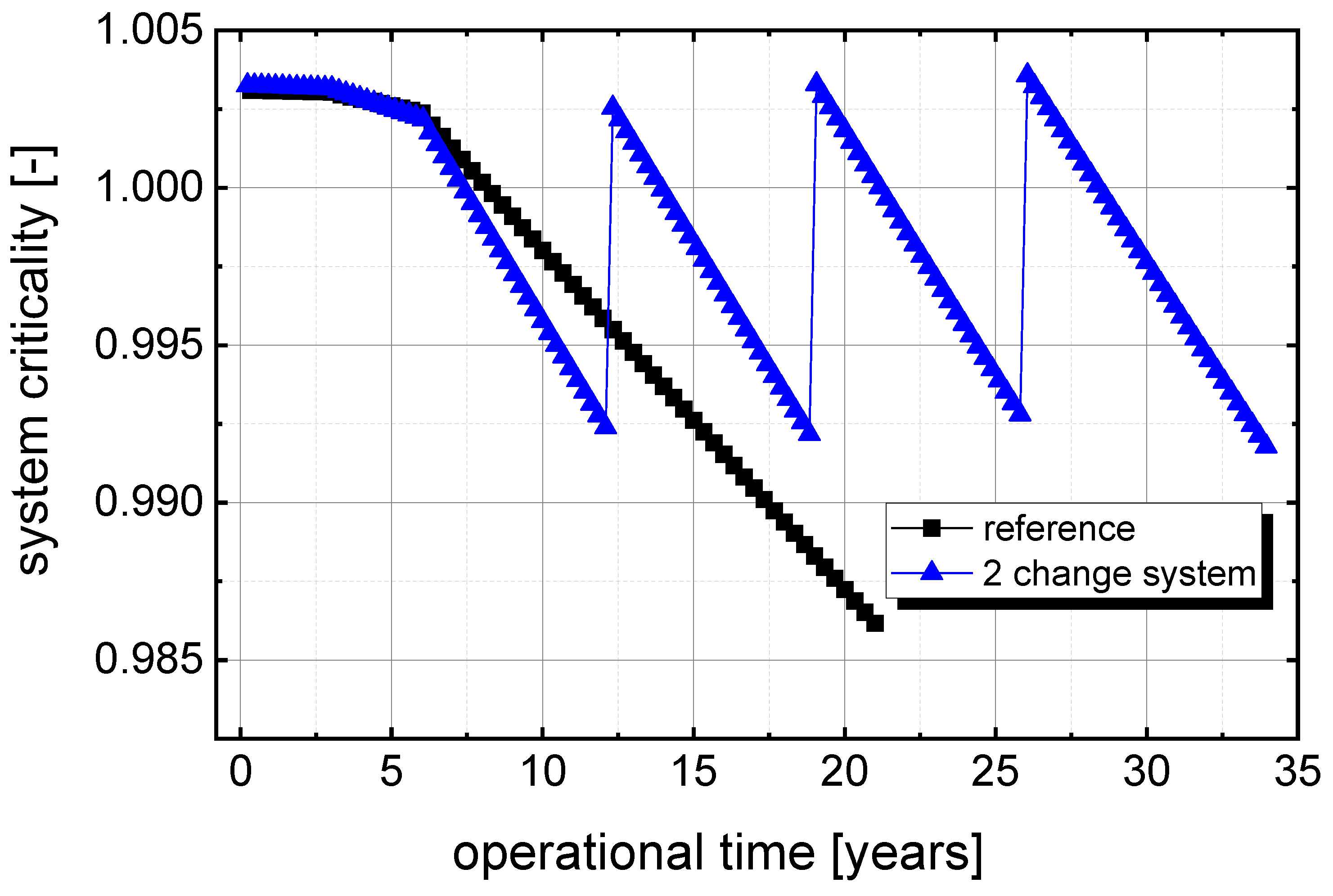
Obviously, the reduction of the sleeve thickness has not been used to the full extent, as the study was aiming only for 20 years of operational time. Thus, in the next step, the maximum achievable operation time will be investigated by using more steps in reducing the sleeve thickness based on the 2-change case (larger steps). The results show that the system criticality can be kept within the limits for almost 35 years, which seems a very reasonable operational time. If an even longer operational lifetime is required, this needs to be considered already in the design stage since a thicker sleeve would have to be planned, and can be based on the almost linear increase of reactivity compensation shown in the initial steps of Table 2.
Figure 15.
System criticality over the potentially achievable operational time exploiting the maximum effect of the insertion of the sleeve for reactivity compensation.
Figure 15.
System criticality over the potentially achievable operational time exploiting the maximum effect of the insertion of the sleeve for reactivity compensation.
The increased operational time will lead to an increase in the neutron flux in the vessel over the extended lifetime due to the reduction of the sleeve thickness, as shown in Figure 16. However, even if the thickness of the sleeve is reduced and the lifetime is extended to almost 35 years, the high-energy neutron flux in the vessel wall stays all the time at a significantly lower level than before the introduction of the sleeve.
The detailed analysis of the lifetime fluence for the reference case at an End of Life (EoL) burnup of 22 GWd/tHM after 20 years and the extended 2 change case leading to a final EoL burnup of almost 55 GWd/tHM after 35 years is given in Table 4. The effect of the sleeve on the reduction of the neutron fluence is very helpful and can be seen with a 45% reduction for neutrons above 100 keV, and more than 80% for neutrons above 1 MeV. Thus, the introduction of the sleeve delivers a massive reduction, and this at a fuel burnup which is increased by a factor of 2.5. The numbers demonstrate the great efficiency of the sleeve in protecting the vessel from the high-energy neutron flux as the source of neutron damage in the vessel material.
4. Discussion
The introduction of the sleeve has strong positive effects on reactivity compensation for burnup, allowing clear fuel cost savings and the reduction of the neutron fluence and thus the radiation damage on the vessel. However, there are also some drawbacks, mainly in the form of demand for an additional component which has to be tailored into the system and will require additional safety evaluations as well as handling of activated components and related low- or medium-level waste production. in addition, based on this study, it can be said that adding a sleeve and optimising the thickness of original reflector can be two sides of the same solution.
The sleeve provides the opportunity for compensation for the reactivity loss as one of the key challenges for a small-scale demonstrator when a design without a mechanical reactivity control system is chosen as a target. Unfortunately, the challenge is much more pronounced in the small-scale demonstrator than in a larger core designed as an iso-breeder. This is due to the very limited breeding opportunity in such a small core. However, the aim to avoid an active mechanical control system is highly attractive as it eliminates one of the most powerful accident initiators, but only if it can be properly demonstrated. This demonstration for the regulator has to be delivered in the first essential development step, such as the small-scale demonstrator.
The positive side effect of the reduced fuel cost is a great opportunity, especially in a fast reactor setup where the fuel cost is one of the dominating cost drivers. However, the fuel saving cost is mainly driven by the improved reflector efficiency and, thus, could likely be achieved through a larger reflector outside of the core, which oppose to the fuel cost
The most interesting side effect of the sleeve, in our view, is the reduction in radiation damage on the vessel, potentially in conjunction with reduced temperatures at the vessel wall and the related slowing down of corrosion effects. The latter two effects should be studied in a coupled neutronic-thermo-fluid dynamic simulation, and applying the resulting data for corrosion studies, including the effect of the small gap between the sleeve and the vessel along with the potential for contact corrosion.
From a radiation protection or damage point of view, the sleeve should be seen as a replaceable sacrificial material to reduce damage to the vessel. This is comparable to the damage of the cladding in solid-fuelled fast reactors, which is one of the life limiting effects of fuel assemblies in SFRs and LFRs. The effect of the reduced fluence on the vessel is maybe not decisive, but should be helpful. For the classification of the effect and the demand for reducing the fluence in LWR, typically, irradiation embrittlement of the reactor pressure vessel (RPV) is to be considered in the areas near the core where neutron irradiation exceeds 1017 n/cm2 (E > 1 MeV) [40,41]. Considering these numbers and the results seen in the study, the simulated system sees much higher fluences for neutrons with energies E>1 MeV (~4 *1021 n/cm2) and furthermore for E>100 keV (3 *1022 n/cm2), thus, a comparison with data from fast reactors seems more adequate
“Fast Breeder Test Reactor (FBTR) has six control rod assemblies with sintered boron carbide pellets inside SS 316 cladding. One of the control rods was discharged after subjecting to a fluence level of 7.0 × 10²² n·cm-2 to assess its irradiation behaviour …”, “The design fluence limit of FBTR control rod is 1.14 × 10²³ n·cm-2.” [44] It is expected that the energy is E>0.1 MeV. The Peak neutron fluence in the PFBR clad and wrapper consisting of 20 % CW Alloy D9 is estimated to ∼ 1.9 × 10²³ n/cm2 (E > 0.1 MeV) at 100GWd/t as design condition. [45]
In JOYO MK-Ⅱ driver fuel assembly, The irradiation conditions of this driver fuel assembly showed a fluence of 8.83 × 10²² n·cm-2 (E>0.1 MeV) [45], The cladding material of these pins is a modified SUS316 stainless steel [46]
The BN-600 components facing maximum neutron fluence (E>0.1 MeV) were the reflector ∼1023, facing swelling, creep, LCF, embrittlement and the headers ∼1022 in the material 18Cr-9Ni [47]. “The maximum neutron fluence on non-replaceable structures of BN-1200 RP will achieve 6⋅1021 cm-2 (with Е>0.1 MeV) on the headers over the operation life.” [47]
Considering this data on already experienced radiation doses and the licensing values, it can be concluded that there is some real operational experience available in austenitic stainless steel up to values well above the calculated fluence of 3 *1022 n/cm2 (E>100 keV). However, the reduction by a factor of ~ 5 through the sleeve seems to be promising, especially when considering a real large power producing machine for later stages.
Finally, the sleeve will help to solve another complex challenge. A system which has to be operated in a limited core volume and relies on feedback from pushing the fuel out of the core due to an increase in temperature will be really complex to design due to the difference between as calculated and as built, as well as due to the uncertainties in the modelling and simulation. The adaption of the sleeve thickness or the determination and manufacturing of the sleeve after the first criticality experiments will allow an adjustment of the core volume after the system is already manufactured.
5. Conclusions
This study demonstrates that the insertion of a replaceable stainless-steel sleeve into the core of a small-scale demonstrator for a molten salt fast reactor offers an effective and innovative solution for compensating burnup-induced reactivity loss without relying on a conventional mechanical control system. The concept directly addresses one of the central challenges of the DEMO reactor, namely maintaining long-term criticality in a burner-type fast reactor with limited breeding capability. The results show that controlled reduction of the sleeve thickness during operation can provide more than 3500 pcm of reactivity compensation, significantly exceeding the reactivity loss observed during the planned operational lifetime.
Beyond reactivity management, the sleeve substantially improves neutron economy of the system through enhanced reflection. Optimisation studies identified an approximately 24 cm thick sleeve as the preferred design option, reducing the fuel inventory required for criticality by about 30% compared with the reference configuration. This reduction lowers fuel demand and the associated costs while simultaneously increasing the achievable burnup from approximately 22 GWd/tHM to nearly 32 GWd/tHM within the original 20-year operational schedule.
A further important benefit is the significant reduction of fast-neutron exposure of the reactor vessel. The sleeve acts as an effective protective barrier, decreasing the lifetime vessel fluence by roughly a factor of 5 for neutrons above 100 keV and by more than a factor of 16 for neutrons above 1 MeV with respect to the reference operating scenario.
The sleeve also provides valuable design flexibility. It offers a practical means of compensating for manufacturing tolerances, modelling uncertainties, and deviations identified during reactor commissioning, thereby supporting the realisation of a reactor concept that depends on precise core-volume control at the first criticality and the use of passive feedback mechanisms for reactor control.
Although additional engineering challenges remain, including component activation, replacement procedures, waste management, and detailed assessment of thermal-hydraulic and corrosion effects, the overall advantages clearly outweigh these drawbacks. Future work should therefore focus on coupled neutronic, thermal-hydraulic, materials, and safety evaluations to support implementation of the concept.
In summary, the sleeve concept provides a simple, robust, and extremely effective multifunctional solution for criticality compensation for a small DEMO core, a very special problem which will not be seen in the ideal iso-breeder. The sleeve simultaneously enables passive reactivity compensation, reduces fuel requirements, increases achievable burnup, and protects the reactor vessel from fast-neutron damage. As such, it represents a highly promising design feature for the DEMO reactor and a potentially valuable technology for future molten salt fast reactor systems.
References
- IAEA. Nuclear Technology Review 2025. GC(69)/INF/9. 2025. [Google Scholar] [CrossRef]
- Shifotoka, Monika. Five Reasons the Clean Energy Transition Needs Nuclear Power. 2026. Available online: https://www.iaea.org/newscenter/news/five-reasons-the-clean-energy-transition-needs-nuclear-power (accessed on 29/07/2026).
- DOE (2023) At COP28, Countries Launch Declaration to Triple Nuclear Energy Capacity by 2050, Recognizing the Key Role of Nuclear Energy in Reaching Net Zero. Available online: https://www.energy.gov/articles/cop28-countries-launch-declaration-triple-nuclear-energy-capacity-2050-recognizing-key (accessed on 29/07/2026).
- Pitois, H.; et al. A Closed Fuel Cycle Option Using the MSFR Concept. GLOBAL, Reims, France, 2022. [Google Scholar]
- Guidez, J.; et al. MSFR Multi Recycling Applications. Proceedings of ICAPP, Juan les Pins – France, 2019. [Google Scholar]
- Merk, B. An Innovative Way of Thinking Nuclear Waste Management. PLOSOne 2017, 12(7). [Google Scholar] [CrossRef] [PubMed]
- Merk, B.; et al. iMAGINE"-" Visions, Missions, and Steps. Energies 2023, 16(7). [Google Scholar] [CrossRef]
- Feynberg, O. MSRs Development in Russia. Kurchatov Institute, presented at ICTP. available, 2019; Available online: https://indico.ictp.it/event/8725/session/1/contribution/4/material/slides/0.pdf (accessed on 29/07/2026).
- Bosbach, D.; Modolo, G.; Tromm, W. Report No.: Contract No.: Förderkennzeichen 1501639A-B; Partitioning and Efficient Transmutation, Studie mit Fokus auf innovativen Strategien in RUSsland (PETRUS). Germany, 2022.
- Haubenreich, P.N.; Engel, J. R.: “Experience with the Molten Salt Reactor Experiment”. Nucl. Appl. Technol. 1970, vol. 8, 107–117. [Google Scholar] [CrossRef]
- MacPherson, H.G. The Molten Salt Reactor Adventure. Nucl. Sci. Eng. 1985, 90, 374–380. [Google Scholar] [CrossRef]
- Bettis, E.S.; Schroeder, R.W.; Cristy, G.A.; Savage, H.W.; Affel, R.G.; Hemphill, L.F. The Aircraft Reactor Experiment—Design and Construction. Nucl. Sci. Eng. 1957, 2(6), 804–25. [Google Scholar] [CrossRef]
- US DOE Advanced Reactor Demonstration Program. Available online: https://www.energy.gov/ne/advanced-reactor-demonstration-program (accessed on 29/07/2026).
- Sackett, J.I. Operating and test experience with EBR-II, the IFR prototype. In Progress in Nuclear Energy; 1997; Volume 31, pp. Issues 1–2. [Google Scholar]
- Ziermann, Egon. Review of 21 years of power operation at the AVR experimental nuclear power station in Jülich. Nucl. Eng. Des. 1990, Volume 121(Issue 2). [Google Scholar] [CrossRef]
- Ignatiev, V. MOSART Fuel Cycle Chemistry Features. International Workshop on the Chemistry of Fuel Cycles for Molten Salt Reactor Technologies, IAEA Headquarters, Vienna, Austria, 2 - 6 October; 2023. Available online: https://nucleus.iaea.org/sites/connect/SFMpublic/WS_on_MSR_Chemistry_2023/Presentations/Day%201/3.6-IAEA%20IGNATIEV%20%20MOSART%202-10-23%20fin.pdf (accessed on 29/07/2026).
- Merk, B. Challenge Areas for Chemistry in Molten Salt Reactors International Workshop on the Chemistry of Fuel Cycles for Molten Salt Reactor Technologies. IAEA Headquarters, Vienna, Austria, 2 - 6 October; 2023. Available online: https://nucleus.iaea.org/sites/connect/SFMpublic/WS_on_MSR_Chemistry_2023/Presentations/Day%201/3.6-IAEA%20IGNATIEV%20%20MOSART%202-10-23%20fin.pdf (accessed on 29/07/2026).
- Merk, B.; et al. Criticality Preserving Without Using a Classical Control System in a Small-Scale Demonstrator for a Molten Salt Fast Reactor, submitted to energies. 2026. [Google Scholar] [CrossRef]
- IAEA-TECDOC-2079; (2025) Analysis and Modelling of Severe Accidents for Liquid Metal Fast Reactors. Available online: https://www.iaea.org/publications/15832/analysis-and-modelling-of-severe-accidents-for-liquid-metal-fast-reactors (accessed on 29/07/2026).
- Bertrand, F.; et al. Severe Accidents in Sodium Fast Reactors: Safety Study Approach, Prevention and Mitigation by Design; Academic Press, 2024. [Google Scholar]
- Moiseev, A. Pilot demonstration reactor BREST-OD-300: conceptual approaches and their implementation. 2021. Available online: https://inis.iaea.org/records/3ab8z-np139 (accessed on 29/07/2026).
- Lange, C.; et al. S. NuCycle: Machbarkeitsstudie zur Umsetzung des Leuchtturmprojektes „Transmutation ohne Wiederaufarbeitung“; Technische Universität Dresden, Institut für Verfahrenstechnik und Umwelttechnik, Professur für Wasserstoff- und Kernenergietechnik (WKET): Dresden, Germany, 2026. [Google Scholar]
- Merk, B.; Detkina, A.; Litskevich, D.; Noori-Kalkhoran, O.; Cartland-Glover, G. A HELIOS-Based Dynamic Salt Clean-Up Study for iMAGINE. Appl. Sci. 2022, 12, 8748. [Google Scholar] [CrossRef]
- Merk, B.; Litskevich, D. Transmutation of All German Transuranium under Nuclear Phase Out Conditions - Is This Feasible from Neutronic Point of View? PLoS ONE 2015, 10(12), e0145652. [Google Scholar] [CrossRef] [PubMed]
- Merk, B.; Rohde, U.; Glivici-Cotruta, V.; Litskevich, D.; Scholl, S. On the Use of a Molten Salt Fast Reactor to Apply an Idealized Transmutation Scenario for the Nuclear Phase Out. PLoS ONE 2014, 9(4). [Google Scholar] [CrossRef] [PubMed]
- HELIOS2 Methods Manual (version 2.03.01). SSP-11/452 Rev 6; Studsvik. 12 January 2021.
- Villarino, E.A.; Stammler, R.J.J.; Ferri, A.; Casal, J.J. HELIOS: angularly dependent collision probabilities. Nuclear Science and Engineering, 1992; 112. [Google Scholar]
- Wemple, C.A.; Gheorghiu, H.-N.M.; Stamm’ler, R.J.J.; Villarino, E.A. 2008) Recent Advances in the HELIOS-2 Lattice Physics Code. International Conference on the Physics of Reactors “Nuclear Power: A Sustainable Resource”, Interlaken, Switzerland, September 14-19, 2008. [Google Scholar]
- Evaluation and Viability of Liquid Fuel Fast Reactor System EVOL, DELIVERABLE D2.1, Design parameters definition for most stable salt flux. 2012, rev 3. [PubMed]
- Brovchenko, M.; et al. Neutronic benchmark of the molten salt fast reactor in the frame of the EVOL and MARS collaborative projects. EPJ Nucl. Sci. Technol. 2019, 5, 2. [Google Scholar] [CrossRef]
- Merk, B.; Detkina, A.; Atkinson, S.; D. Litskevich, G. Catland-Glover: Evaluation of the Breeding Performance of a NaCl-UCl-Based Reactor System. Energies 2019, 12(20), 3853. [Google Scholar] [CrossRef]
- SSP-11/451 Rev 8; AURORA USER MANUAL. Studsvik, 12 January 2021.
- SSP-11/460 Rev. 5; ZENITH USER MANUAL. Studsvik, 8 December 2020.
- Merk, B.; Litskevich, D. On the Burning of Plutonium Originating from Light Water Reactor Use in a Fast Molten Salt Reactor-A Neutron Physical Study. ENERGIES 2015, 8(11), 12557–12572. [Google Scholar] [CrossRef]
- Merk, B.; Litskevich, D. A disruptive approach to eliminating weapon-grade plutonium – Pu burning in a molten salt fast reactor. PLoS ONE 2018, 13(8), e0201757. [Google Scholar] [CrossRef]
- Rachamin, R.; Wemple, C.; Fridman, E. Neutronic analysis of SFR core with HELIOS-2, Serpent, and DYN3D codes. Ann. Nucl. Energy 2013, Volume 55. [Google Scholar] [CrossRef]
- Detkina; Litskevich, D.; Drury, M.; Merk, B. Zero Power Experiment for Molten Salt Reactor -- Code Verification and Validation Request. International Conference on Physics of Reactors, Pittsburgh, United States, 2022. [Google Scholar]
- Merk, B.; Litskevich, D.; Gregg, R.; Mount, A.R. Demand driven salt clean-up in a molten salt fast reactor–Defining a priority list. PLoS ONE 2018, 13(3), e0192020. [Google Scholar] [CrossRef] [PubMed]
- Merk, B.; Detkina, A.; Litskevich, D.; Drury, M.; Noori-kalkhoran, O.; Cartland-Glover, G.; Petit, L.; Rolfo, S.; Elliott, J.P.; Mount, A.R. Defining the Challenges—Identifying the Key Poisoning Elements to Be Separated in a Future Integrated Molten Salt Fast Reactor Clean-Up System for iMAGINE. Appl. Sci. 2022, 12, 4124. [Google Scholar] [CrossRef]
- Merk, B.; Detkina, A.; Litskevich, D.; Atkinson, S.; Cartland-Glover, G. The Interplay between Breeding and Thermal Feedback in a Molten Chlorine Fast Reactor. Energies 2020, 13, 1609. [Google Scholar] [CrossRef]
- Merk, B.; Glivici-Cotruţă, V.; Weiß, F.P. On the use of different analytical solutions for recalculation of the YALINA-Booster experiment SC3A. Prog. Nucl. Energy 2012, Volume 58. [Google Scholar] [CrossRef]
- 1.4 Materials in 1. Materials Ageing – Irradiation Embrittlement. Available online: https://joint-research-centre.ec.europa.eu/euratom-materials-ageing-research-emar-knowledge-base/emar-synthesis-reports/reactor-systems-gen-iiiii-lto/1-materials-ageing-irradiation-embrittlement/14-materials_en.
- Safety Standards of the Nuclear Safety Standards Commission (KTA), KTA 3201.2 (2017-11) Components of the Reactor Coolant Pressure Boundary of Light Water Reactors Part 2: Design and Analysis. Available online: https://www.kta-gs.de/e/standards/3200/3201_2_engl_2017_11.pdf.
- MURALIDHARAN, N.G.; VENKITESWARAN, C.N.; KARTHIK, V.; ANANDRAJ, V.; JOSEPH, J.; KASIVSWANATHAN, K.V.; VENUGOPAL, S.; JAYAKUMAR, T.; RAJ, B. 2011) POST-IRRADIATION EXAMINATION OF FUEL AND CORE STRUCTURAL MATERIALS IRRADIATED IN FAST BREEDER TEST REACTORS. Available online: https://www-pub.iaea.org/MTCD/Publications/PDF/TE_1693_CD_web.pdf (accessed on 12/08/2026).
- Karthik, V.; Kumar, Ran Vijay; Anandaraj, V.; Padmaprabu, C.; Vijayaragavan, A.; Jayaraj, V.V.; Venkiteswaran, C.N.; Kurien, Shaji; Divakar, R. Irradiation behaviour of alloy D9 clad and wrapper in FBTR. J. Nucl. Mater. 2022, Volume 565. [Google Scholar] [CrossRef]
- ICHIKAWA, S.; HAGA, H.; KATSUYAMA, K.; K. MAEDA, T. NAGAMINE (2011) ESTABLISHMENT OF THE DISASSEMBLING TECHNIQUE OF THE DRIVER FUEL ASSEMBLY IRRADIATED IN JOYO. Available online: https://www-pub.iaea.org/MTCD/Publications/PDF/TE_1693_CD_web.pdf (accessed on 12/08/2026).
- Inoue, Masaki; Maeda, Koji; Katsuyama, Kozo; Tanaka, Kosuke; Mondo, Kenji; Hisada, Masaki. Fuel-to-cladding gap evolution and its impact on thermal performance of high burnup fast reactor type uranium–plutonium oxide fuel pins. J. Nucl. Mater. 2004, Volume 326(Issue 1). [Google Scholar] [CrossRef]
- Vasilyev, B.A.; Vilensky, O.Yu.; Kaidalov, V.B. Validation of BN reactor plant long-term operation. n.d. Available online: https://www-pub.iaea.org/MTCD/Publications/PDF/SupplementaryMaterials/P1665CD/Track9_Decommissioning.pdf (accessed on 12/08/2026).
Figure 1.
Volume-corrected 2D HELIOS model of the molten salt reactor.
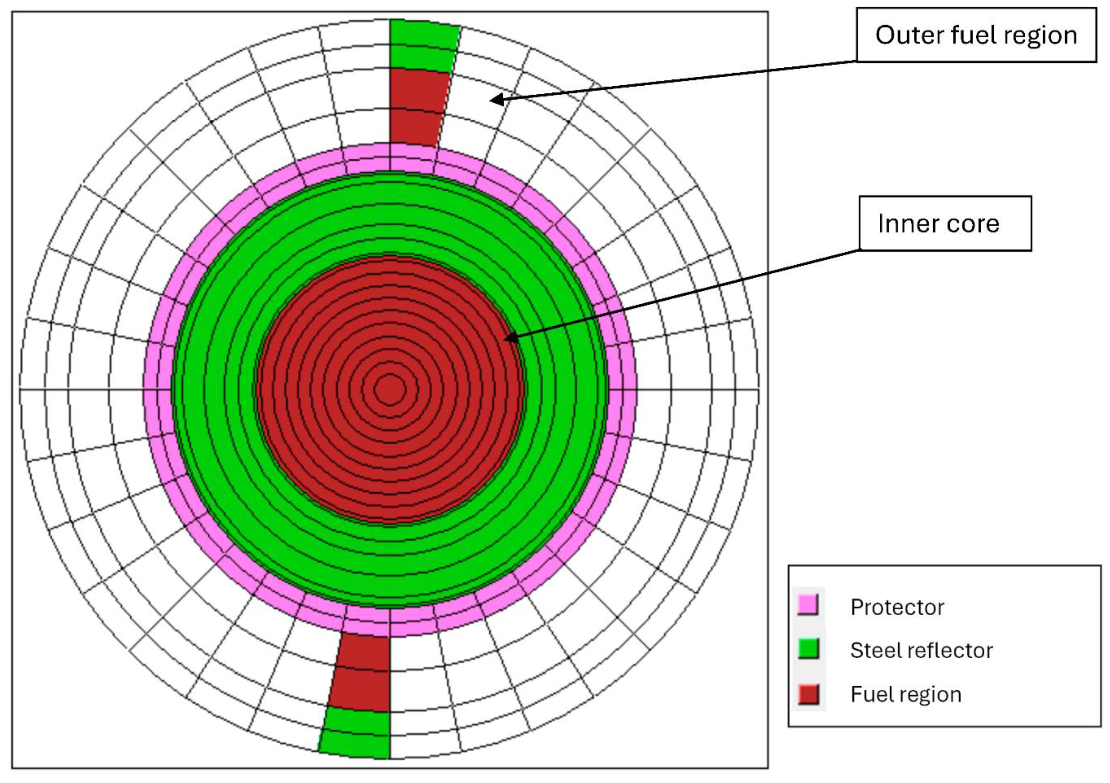
Figure 2.
Description of the calculation cycle for the simulation of an MSR, based on the HELIOS package.
Figure 2.
Description of the calculation cycle for the simulation of an MSR, based on the HELIOS package.
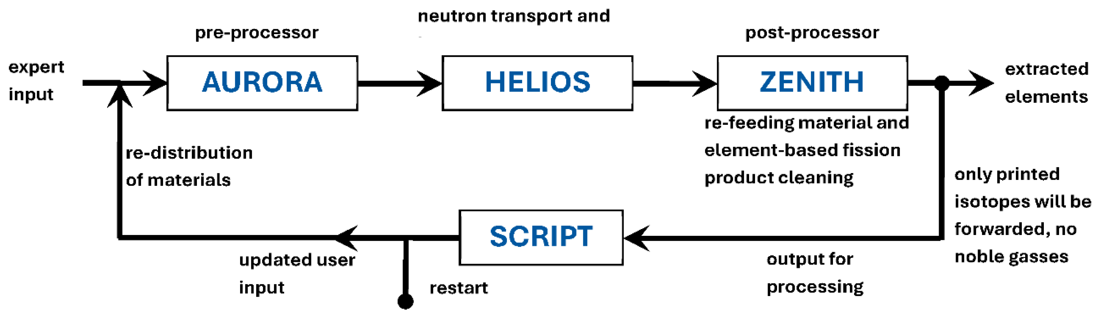
Figure 3.
System criticality over burnup (left) and over operational time (right) for the demonstrator core as reference system with 19.9% enrichment U-235 feeding provided.
Figure 3.
System criticality over burnup (left) and over operational time (right) for the demonstrator core as reference system with 19.9% enrichment U-235 feeding provided.
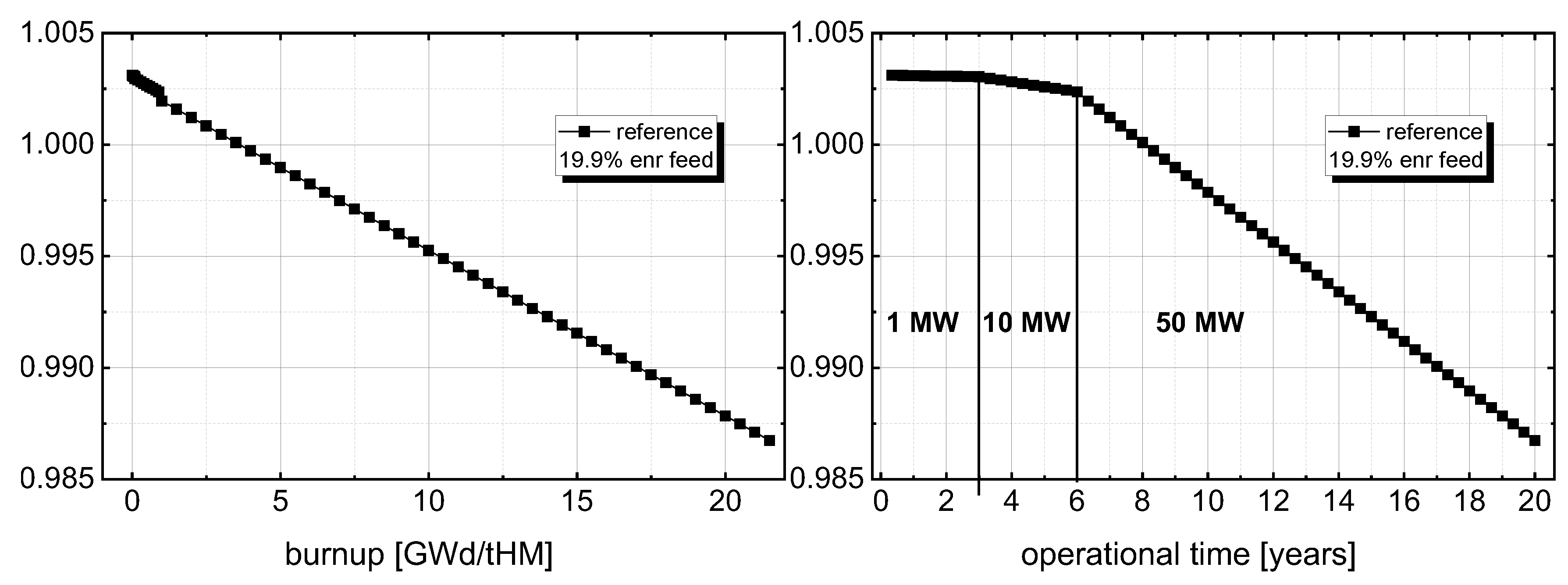
Figure 4.
HELIOS test core model with inserted sleeve, see detail.
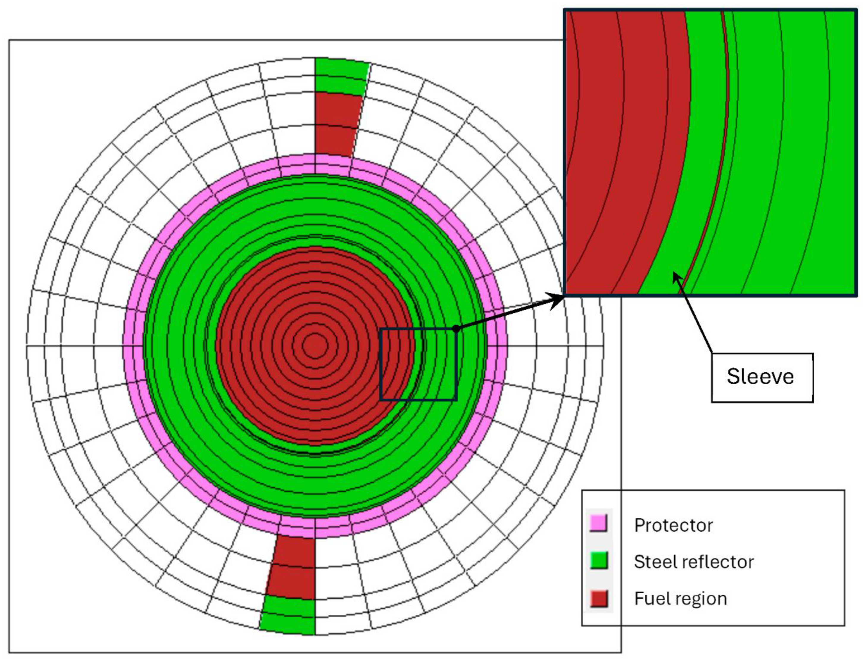
Figure 5.
Comparison of the system criticality over operational time for the demonstrator core between the reference solution and two different approaches for changing the thickness of the sleeve.
Figure 5.
Comparison of the system criticality over operational time for the demonstrator core between the reference solution and two different approaches for changing the thickness of the sleeve.
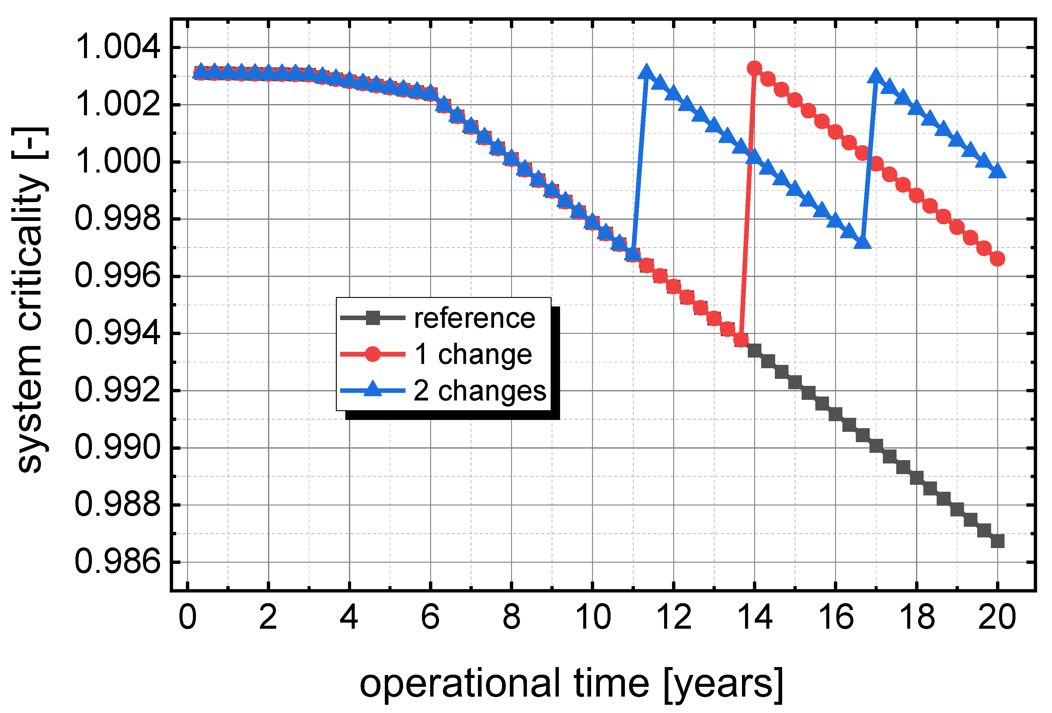
Figure 6.
HELIOS model with strongly refined discretisation used for the optimisation of the sleeve thickness and the determination of the reactivity change through reduction of the thickness (left case without sleeve, right with stainless steel sleeve).
Figure 6.
HELIOS model with strongly refined discretisation used for the optimisation of the sleeve thickness and the determination of the reactivity change through reduction of the thickness (left case without sleeve, right with stainless steel sleeve).
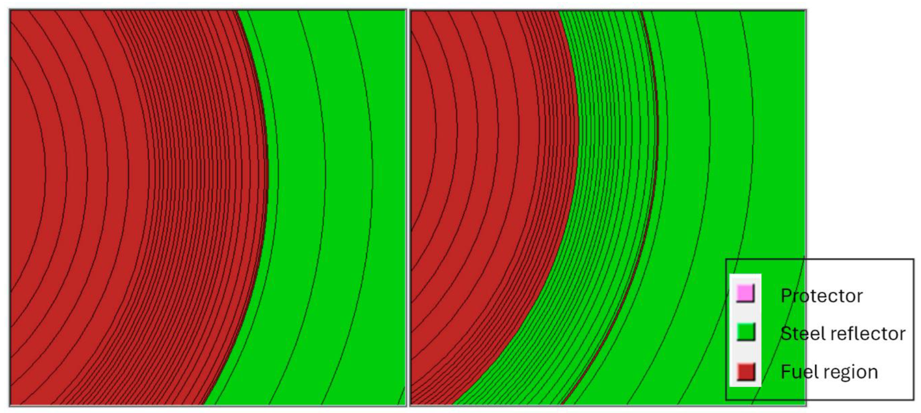
Figure 7.
Effect of the sleeve thickness on the fuel volume required to achieve criticality.
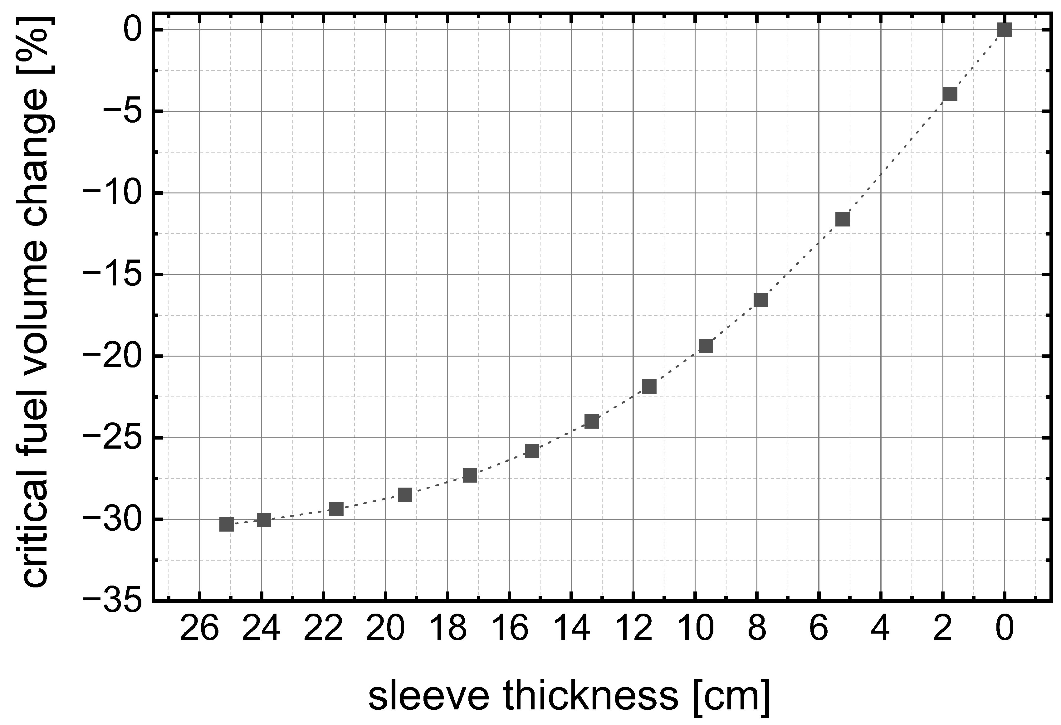
Figure 8.
Relative reactivity change resulting from the stepwise reduction of the sleeve thickness.
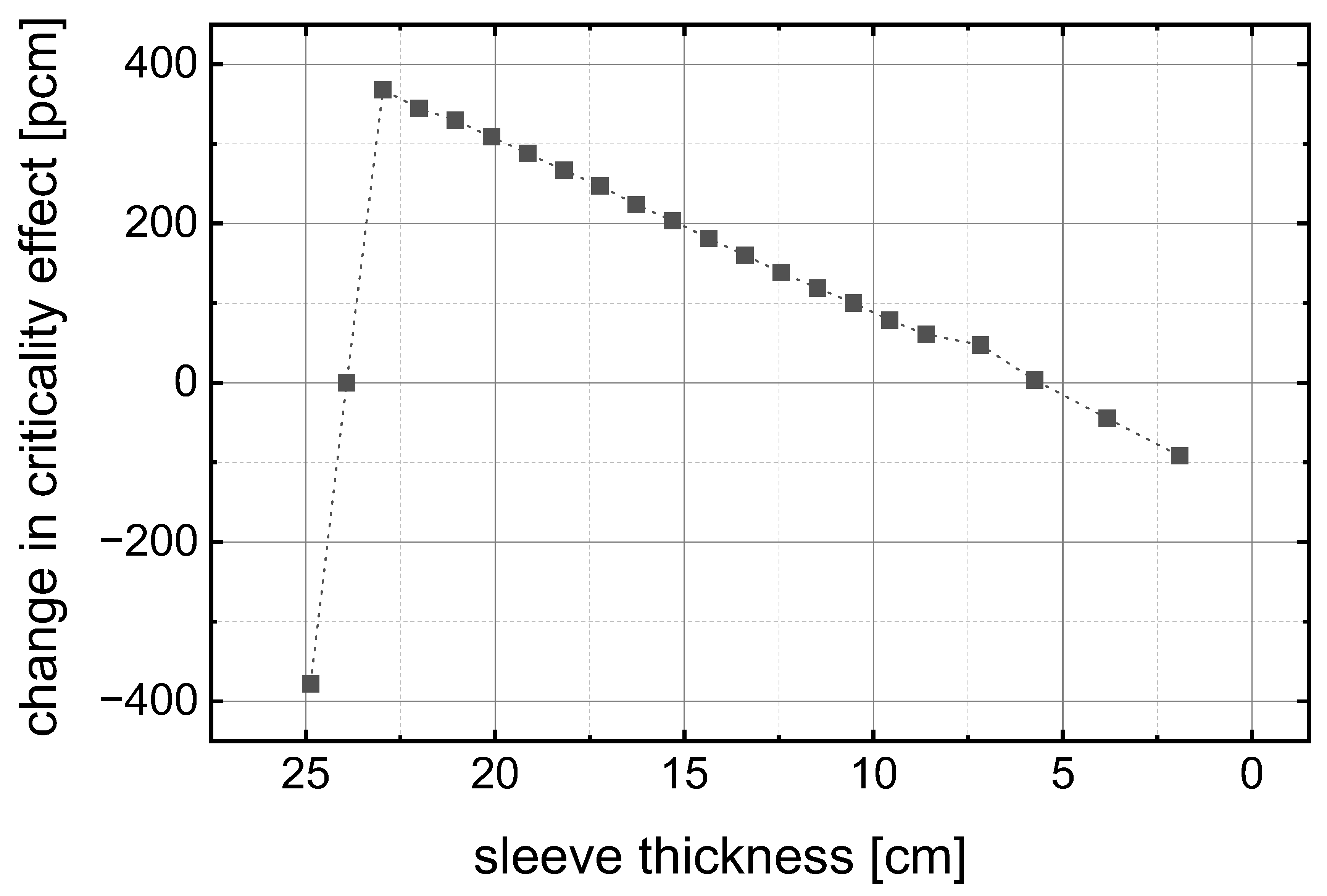
Figure 9.
Absolute reactivity change resulting from a specific reduction of the sleeve thickness.
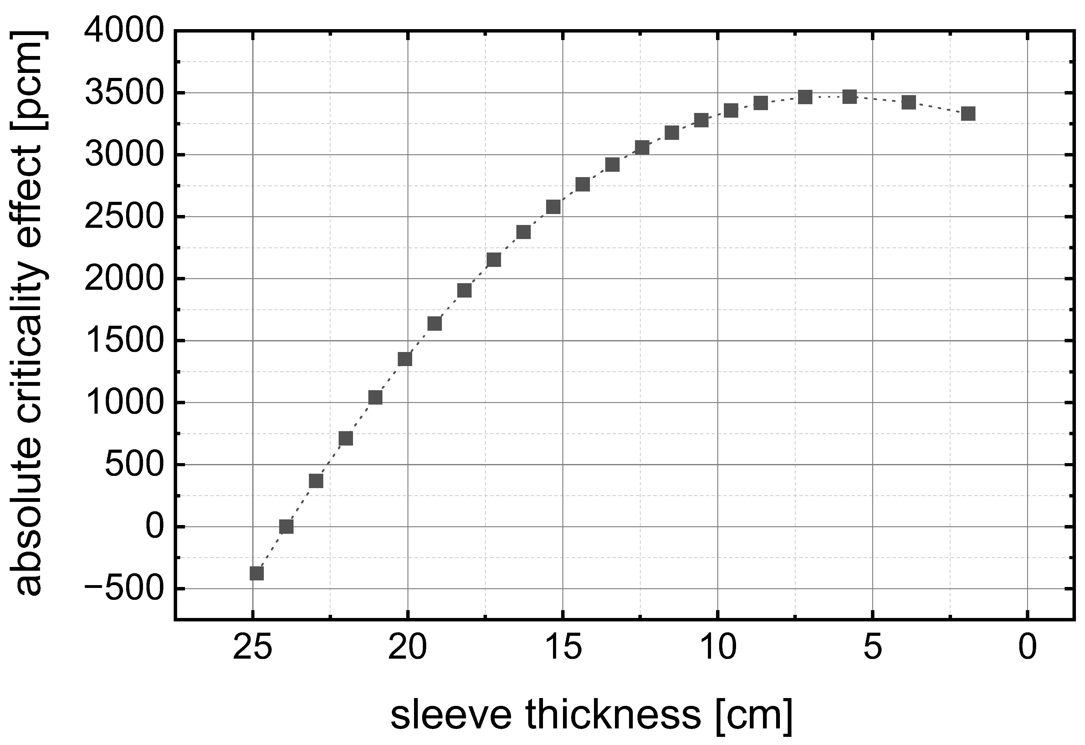
Figure 10.
System criticality over operational time before and after the insertion of the sleeve for reactivity compensation using the refined discretisation scheme.
Figure 10.
System criticality over operational time before and after the insertion of the sleeve for reactivity compensation using the refined discretisation scheme.
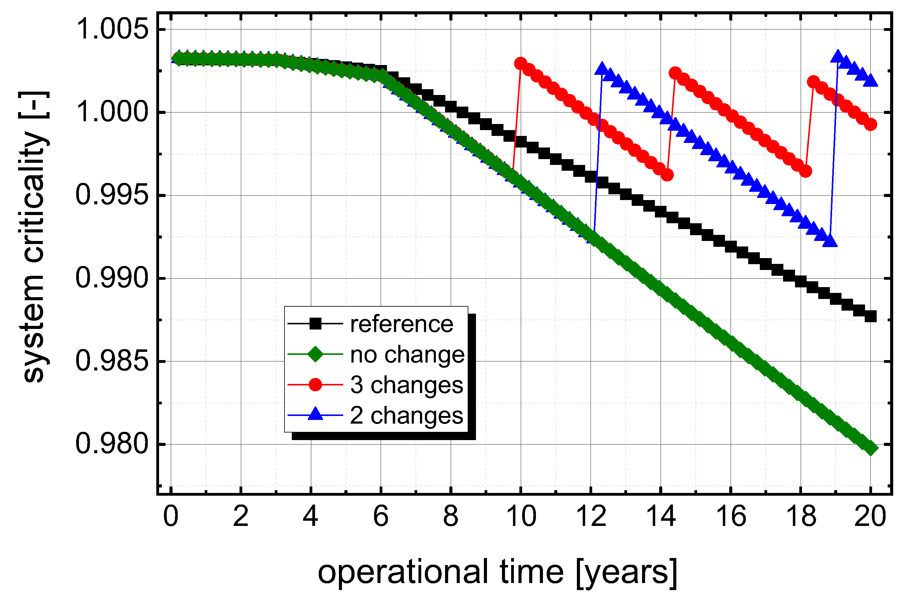
Figure 11.
Power density distribution in a core traverse from the centre to the outer core regions for the reference case and the case with a 24 cm thick sleeve.
Figure 11.
Power density distribution in a core traverse from the centre to the outer core regions for the reference case and the case with a 24 cm thick sleeve.
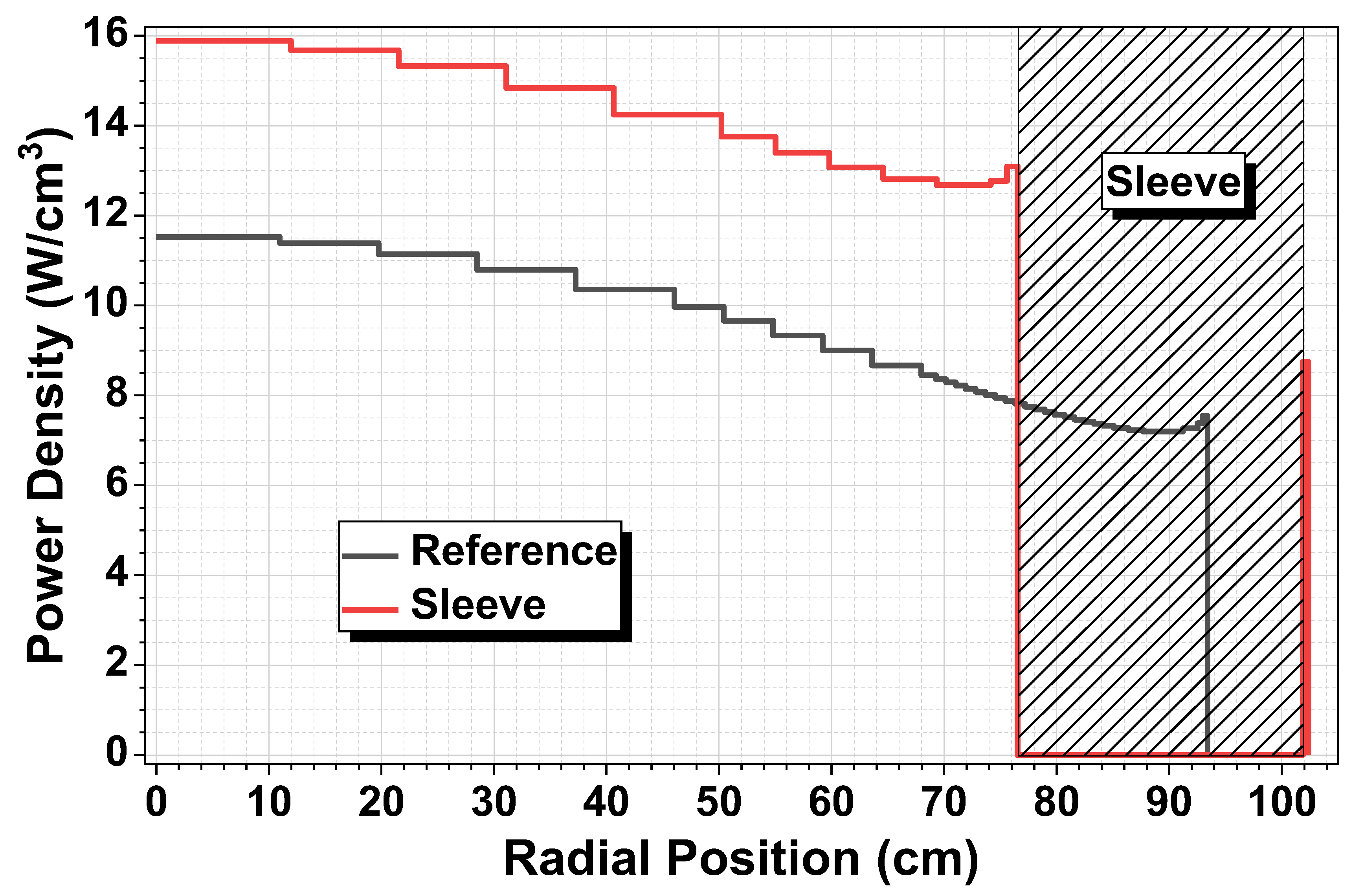
Figure 12.
Radial distribution of the high-energy neutron flux (E>100keV) for the reference case and the system with the added sleeve.
Figure 12.
Radial distribution of the high-energy neutron flux (E>100keV) for the reference case and the system with the added sleeve.
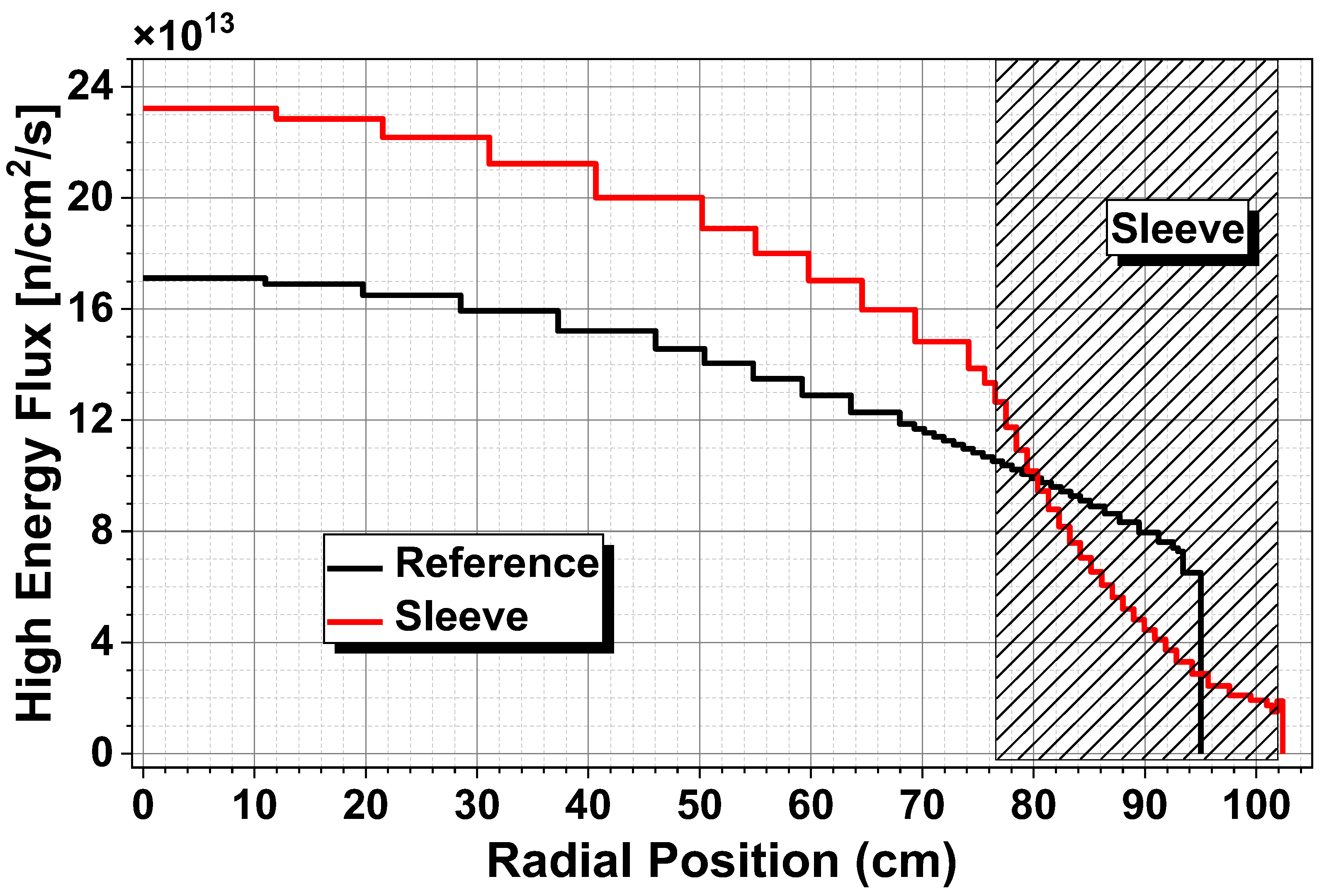
Figure 13.
Radial distribution of the low-energy neutron flux (E<100keV) for the reference case and the system with the added sleeve.
Figure 13.
Radial distribution of the low-energy neutron flux (E<100keV) for the reference case and the system with the added sleeve.
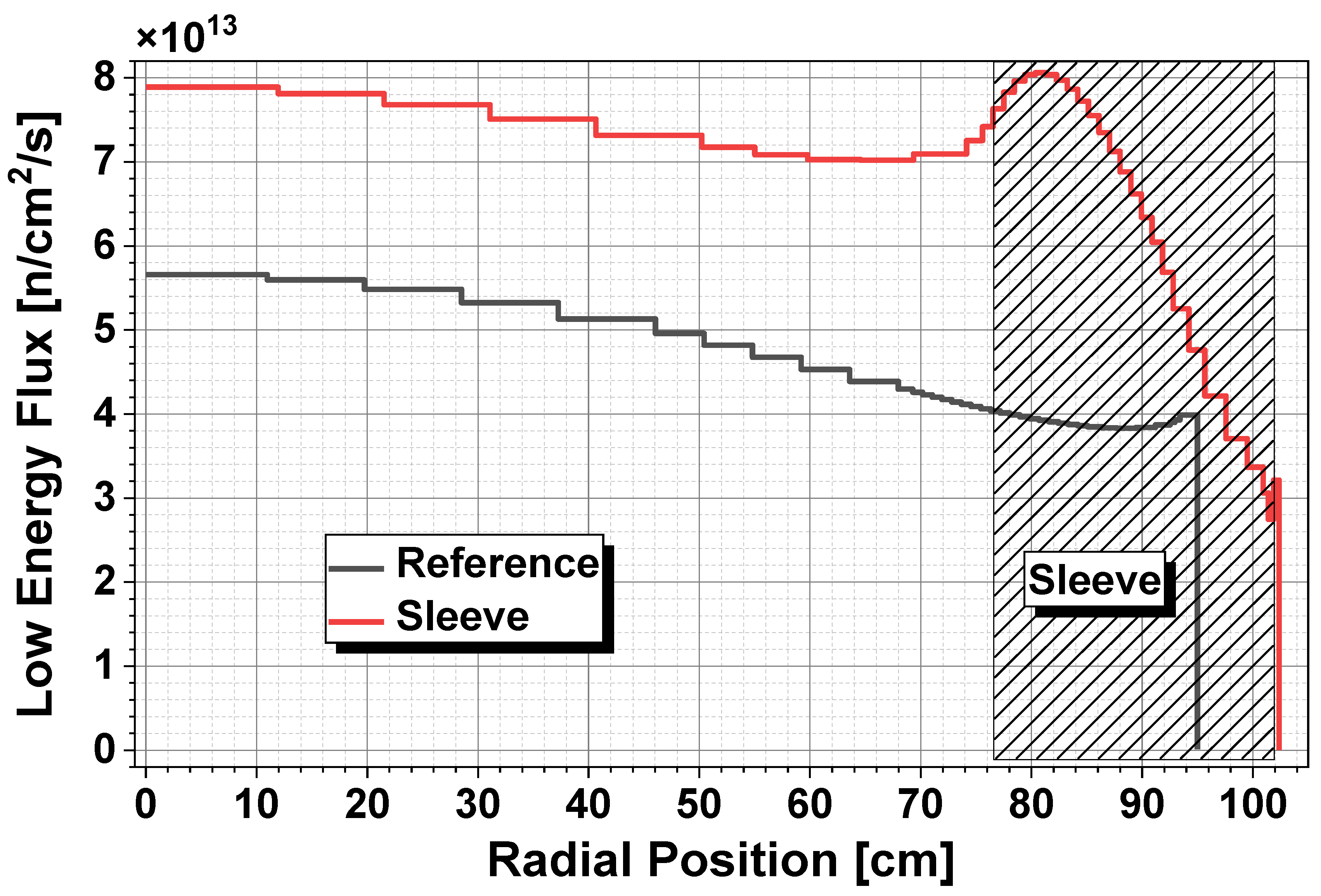
Figure 14.
High-energy neutron flux (E>100 keV) in the core vessel over the operational period of 20 years for the reference case and different cases with reduced sleeve thickness for reactivity loss compensation.
Figure 14.
High-energy neutron flux (E>100 keV) in the core vessel over the operational period of 20 years for the reference case and different cases with reduced sleeve thickness for reactivity loss compensation.
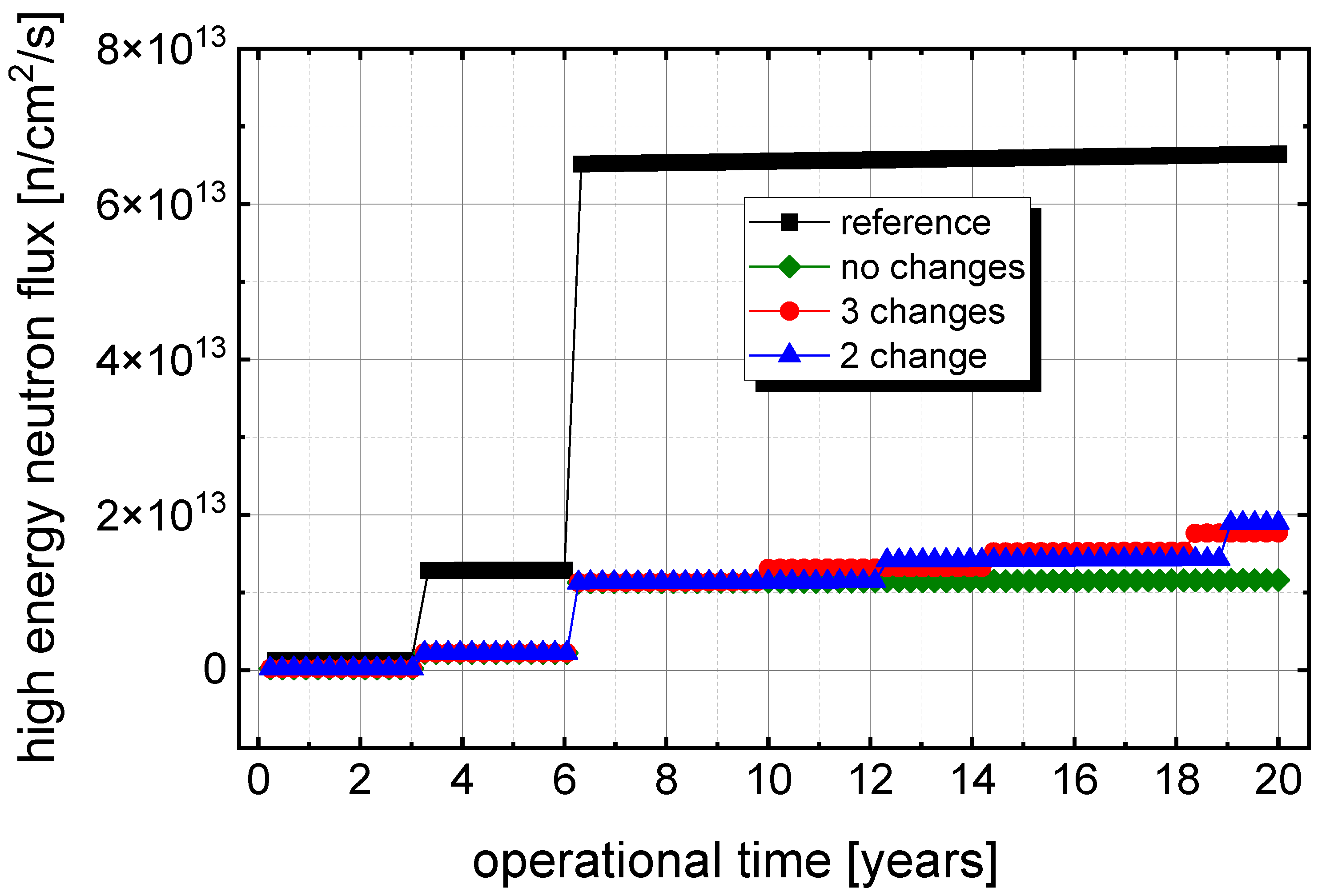
Figure 16.
High energy neutron flux (E>100 keV) in the core vessel over the potential maximum operational time, reference case and the extended 2 change case with stepwise reduced sleeve thickness for reactivity loss compensation.
Figure 16.
High energy neutron flux (E>100 keV) in the core vessel over the potential maximum operational time, reference case and the extended 2 change case with stepwise reduced sleeve thickness for reactivity loss compensation.
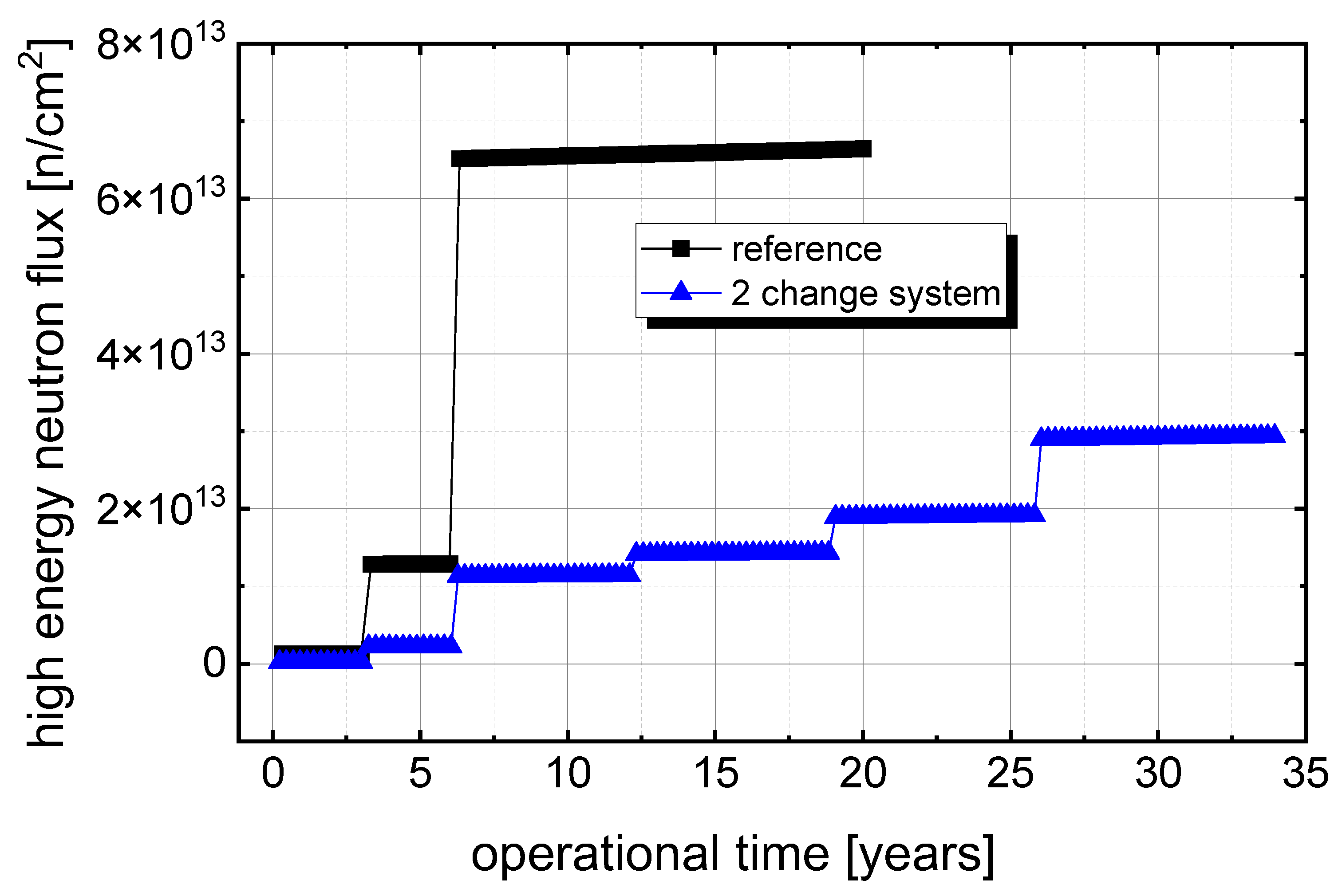

Table 1.
Effect of the sleeve thickness on the fuel volume required to achieve identical criticality and fuel volume change compared to the reference case.
Table 1.
Effect of the sleeve thickness on the fuel volume required to achieve identical criticality and fuel volume change compared to the reference case.
| Unit inside | Inner diameter sleeve [cm] | Inner diameter vessel [cm] | Outer diameter sleeve [cm] | Sleeve thickness [cm] | Fuel volume [cm3] | CriticalVolume [%] | Volume change [%] |
| 160 | 154.65 | 205.88 | 204.91 | 25.13 | 3628130 | 69.68 | -30.32 |
| 162 | 154.98 | 203.77 | 202.81 | 23.92 | 3642117 | 69.94 | -30.06 |
| 166 | 155.77 | 199.88 | 198.94 | 21.58 | 3676802 | 70.61 | -29.39 |
| 170 | 156.81 | 196.48 | 195.55 | 19.37 | 3723428 | 71.51 | -28.49 |
| 174 | 158.15 | 193.60 | 192.69 | 17.27 | 3784756 | 72.68 | -27.32 |
| 178 | 159.82 | 191.24 | 190.35 | 15.26 | 3862657 | 74.18 | -25.82 |
| 182 | 161.81 | 189.37 | 188.48 | 13.34 | 3957027 | 75.99 | -24.01 |
| 186 | 164.12 | 187.94 | 187.06 | 11.47 | 4068745 | 78.14 | -21.86 |
| 190 | 166.74 | 186.93 | 186.05 | 9.65 | 4197900 | 80.62 | -19.38 |
| 194 | 169.67 | 186.29 | 185.41 | 7.87 | 4344370 | 83.43 | -16.57 |
| 200 | 174.69 | 186.04 | 185.17 | 5.24 | 4602016 | 88.38 | -11.62 |
| 208 | 182.21 | 186.58 | 185.71 | 1.75 | 5002761 | 96.07 | -3.93 |
| 212 | 185.92 | 186.80 | 185.92 | 0.00 | 5207171 | 100.00 | 0.00 |
Table 2.
Reactivity gain per step for the stepwise reduction of the thickness of the sleeve.
| Unit inside | System criticality [-] | Sleeve thickness [cm] | Reactivity gain relative [pcm] | Reactivity gain absolute [pcm] |
| 160 | 0.9995585 | 24.87 | -378.2 | -378.2 |
| 162 | 1.003352 | 23.92 | 0 | 0 |
| 164 | 1.007067 | 22.96 | 367.7 | 367.7 |
| 166 | 1.010573 | 22.00 | 344.5 | 712.2 |
| 168 | 1.013949 | 21.05 | 329.5 | 1041.6 |
| 170 | 1.017134 | 20.09 | 308.8 | 1350.5 |
| 172 | 1.020120 | 19.13 | 287.8 | 1638.2 |
| 174 | 1.022902 | 18.18 | 266.6 | 1904.8 |
| 176 | 1.025494 | 17.22 | 247.1 | 2151.9 |
| 178 | 1.027849 | 16.26 | 223.4 | 2375.4 |
| 180 | 1.030003 | 15.31 | 203.5 | 2578.8 |
| 182 | 1.031931 | 14.35 | 181.4 | 2760.2 |
| 184 | 1.033639 | 13.39 | 160.1 | 2920.3 |
| 186 | 1.035121 | 12.44 | 138.5 | 3058.9 |
| 188 | 1.036395 | 11.48 | 118.8 | 3177.6 |
| 190 | 1.037473 | 10.52 | 100.3 | 3277.9 |
| 192 | 1.038317 | 9.57 | 78.3 | 3356.2 |
| 194 | 1.038972 | 8.61 | 60.7 | 3416.9 |
| 197 | 1.039484 | 7.17 | 47.4 | 3464.3 |
| 200 | 1.039521 | 5.74 | 3.4 | 3467.8 |
| 204 | 1.039040 | 3.83 | -44.5 | 3423.2 |
| 208 | 1.038049 | 1.91 | -91.9 | 3331.4 |
Table 3.
Neutron fluence accumulated over the planned operational time of 20 years for the reference case and the cases with the inserted sleeve.
Table 3.
Neutron fluence accumulated over the planned operational time of 20 years for the reference case and the cases with the inserted sleeve.
|
Ref no sleeve |
Sleeve 2 changes |
Sleeve 3 changes |
Sleeve No change |
|
| Lifetime fluence E>100keV [n/cm2] |
3.036E+22 | 6.043E+21 | 6.259E+21 | 5.207E+21 |
| Lifetime fluence E>1MeV [n/cm2] |
4.138E+21 | 2.482E+20 | 2.512E+20 | 2.058E+20 |
Table 4.
End of Life fluence in the vessel wall for the reference case and the extended operation with sleeve.
Table 4.
End of Life fluence in the vessel wall for the reference case and the extended operation with sleeve.
|
Ref no sleeve 22 GWd/tHM |
Sleeve extended 2 changes case ~55 GWd/tHM |
|
| Lifetime fluence E>100keV [n/cm2] |
3.036E+22 | 1.688E+22 |
| Lifetime fluence E>1MeV [n/cm2] |
4.138E+21 | 8.337E+20 |
Disclaimer/Publisher’s Note: The statements, opinions and data contained in all publications are solely those of the individual author(s) and contributor(s) and not of MDPI and/or the editor(s). MDPI and/or the editor(s) disclaim responsibility for any injury to people or property resulting from any ideas, methods, instructions or products referred to in the content. |
© 2026 by the authors. Licensee MDPI, Basel, Switzerland. This article is an open access article distributed under the terms and conditions of the Creative Commons Attribution (CC BY) license (http://creativecommons.org/licenses/by/4.0/).
Copyright: This open access article is published under a Creative Commons CC BY 4.0 license, which permit the free download, distribution, and reuse, provided that the author and preprint are cited in any reuse.