

Submitted:
20 September 2026
Posted:
21 September 2026
You are already at the latest version
Abstract
The symbol θ is used in reinforced-concrete analysis for several physically different quantities. In two-way slabs these include the strut-and-tie-model (STM) strut inclination, a spacing-based geometric load-diffusion angle, reinforcement-family and yield-line orientations, crack-normal misalignment, and the inclination associated with tensile membrane action. Treating these quantities as interchangeable can produce misleading comparisons between reinforcement spacing and code provisions. This paper establishes a unified framework for conventional orthogonal (0°/90°) and triaxial (0°/60°/120°) reinforcement. The triaxial network is described as a planar triangular reinforcement lattice, while a hexagonal cell is used only as a geometric representation. The geometric dispersion angle is defined using nodal pitch rather than the perpendicular bar spacing. For the orthogonal mesh ℓ_o=s_o, whereas for the triaxial mesh ℓ_h=2s_h/√3. Combining this geometry with the reinforcement-density transformation gives tanθ_h=(R_h/√3)tanθ_o. The frequently cited 1.85d value is shown to be a derived geometric expression associated with a 25° reference under the adopted triaxial geometry; it is not presented as an independent reinforcement-spacing requirement of ACI. A new analytical framework is introduced for nodal force transfer, idealized directional response, three-dimensional load-path geometry, and possible confinement effects. The confinement and strain-energy interpretations are explicitly treated as research hypotheses rather than established mechanisms because their quantitative calibration for triaxial slab reinforcement is not available. The S1–S10 ABAQUS matrix from the source finite-element study is used as a numerical illustration. Particular attention is given to S8 and S9: with the density definitions used here, S9 contains 25% of the total steel density of S8, not 50%; S9 is 50% of the orthogonal 120-mm reference used in the same model family. The results show that θ_d does not uniquely control ultimate pressure. Accordingly, θ_d is proposed as a geometric/detailing and load-path screening descriptor, whereas θ_STM should be obtained from actual compression trajectories in mechanically appropriate discontinuity regions.
Keywords:
triaxial reinforcement
; triangular lattice
; hexagonal cell representation
; two-way slabs
; strut-and-tie model
; load-diffusion angle
; yield-line theory
; ABAQUS
; confinement hypothesis
; tensile membrane action
1. Introduction
Two-way reinforced-concrete slabs are normally detailed with two orthogonal reinforcement families. Three-way reinforcement arranged at 0°, 60°, and 120° has also been investigated in containment and shell-type structures [5]. The present research considers a planar triaxial reinforcement network embedded within a two-way slab and compares it with a conventional orthogonal mesh using the ten-model ABAQUS matrix S1–S10 reported in the source finite-element study [2].
A central difficulty is the overloaded symbol θ. In an STM, θ describes the inclination of an assumed compression strut relative to a tie within a selected discontinuity region. In the present reinforcement study, a second angle can be constructed directly from the reinforcement-network geometry and effective depth. Other angles describe reinforcement orientation, yield-line or crack-normal orientation, directional misalignment, or the slope of a large-deflection membrane configuration. These quantities answer different mechanical questions and should not be assigned the same code status.
The objective of this paper is therefore not to propose a universal θ acceptance limit. Instead, the paper develops a consistent mechanical and geometric interpretation of θ for orthogonal and triaxial reinforcement, introduces an analytical framework for the proposed force-transfer mechanism, and compares the resulting descriptors with the reported ABAQUS response. The paper also separates practical bar-size effects from topology effects and defines a verification protocol required before any new θ limit or reinforcement-reduction rule can be generalized.
2. Theoretical and Analytical Framework
2.1. Geometry and Topology of the Triaxial Network
The 0°/60°/120° arrangement is treated as a planar triaxial triangular reinforcement network. The reinforcement intersections form a triangular lattice, whereas the regular hexagon is used only as a convenient cell representation of the same topology. This terminology avoids implying that the reinforced-concrete slab is a literal honeycomb or that cellular-solids constitutive laws can be transferred directly to reinforced concrete.
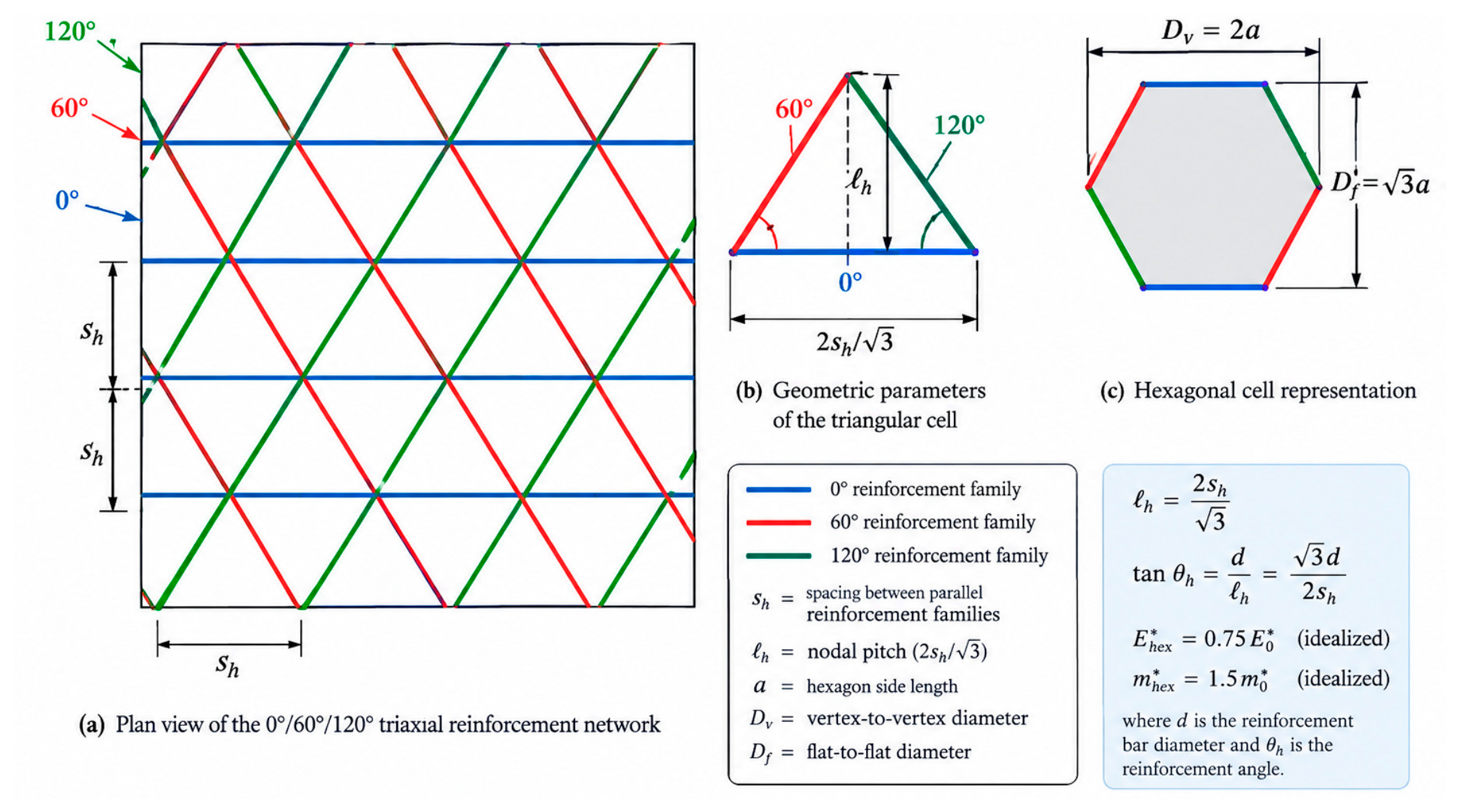
For one reinforcement family, s_h denotes the perpendicular spacing between parallel bars. The distance between adjacent nodes measured along the corresponding reinforcement family is the nodal pitch ℓ_h. The geometry of the equilateral triangular cell gives:
where d is the effective depth used in the geometric screening calculation. Figure 1 defines the three reinforcement families, the triangular-cell geometry, and the corresponding hexagonal representation.
ℓ_h = s_h / sin 60° = 2s_h/√3
tan θ_d,h = d/ℓ_h = √3 d/(2s_h)
2.2. Nodal Force Transfer and Vector Equilibrium
At an idealized interior node, the three reinforcement directions are separated by 120° when their undirected axes are considered as line families. Unit vectors may be written as:
e₁=(1,0), e₂=(−1/2,√3/2), e₃=(−1/2,−√3/2)
These vectors satisfy e₁+e₂+e₃=0. Consequently, a set of equal internal directional forces can form a self-equilibrated vector system. Under an externally applied nodal resultant P, however, the reinforcement forces must satisfy the full equilibrium equation:
T₁e₁ + T₂e₂ + T₃e₃ + P = 0
The values of T₁, T₂, and T₃ therefore depend on the applied resultant, boundary conditions, bond, stiffness, and the surrounding concrete continuum. Equal directional reactions are a special symmetric case and should not be imposed as a universal nodal-force formula. Likewise, vector symmetry does not prove that the concrete shear stress τ_xy is identically zero. The appropriate interpretation is that the three-family topology can reduce directional bias in the idealized reinforcement response; the actual concrete stress field must be obtained from finite-element results.
2.3. Idealized In-Plane Directional Response
The directional response of the reinforcement topology can be examined independently of the nonlinear behaviour of the concrete. For an orthogonal steel network with total reinforcement ratio ρ_o and steel modulus E_s, an idealized fourth-power projection gives:
E_o(φ)/(E_sρ_o) = cos⁴φ + sin⁴φ
For the triaxial network, let ρ_3 be the total steel ratio distributed equally among the three families. The corresponding idealized directional stiffness is:
E_h(φ)/(E_sρ_o) = (ρ_3/ρ_o) Σ[k=0 to 2] cos⁴(φ−kπ/3)
At equal total steel, ρ_3=ρ_o. If the expression is instead normalized by the orthogonal reference while each triaxial family carries two-thirds of the corresponding orthogonal-family steel, the family-density factor is 2/3. The directional identity
shows that the corresponding idealized steel-only stiffness becomes constant when the three families are equally distributed. With the 2/3 family normalization used in the source framework:
Σ[k=0 to 2] cos⁴(φ−kπ/3) = 9/8
E_h/(E_sρ_o) = (2/3)(9/8) = 3/4
This is an idealized topology-level result, not a statement that the complete reinforced-concrete slab is materially isotropic. Concrete cracking, bond, anchorage, boundary conditions, and nonlinear constitutive behaviour can all introduce directional effects.
The same three-family geometry produces an idealized normal plastic-moment projection:
m_n(φ) = m_f Σ[k=0 to 2] cos²(φ−kπ/3) = 1.5m_f
If equal total steel is imposed and each triaxial family contains two-thirds of the corresponding orthogonal-family steel, then m_n,trix=1.5(2/3)m_0=m_0. The factor 1.5 is therefore a per-family projection identity and must not be interpreted as a prediction of 50% higher real slab capacity.
2.4. Three-Dimensional Load Transfer and Strut Geometry
The triaxial reinforcement network can be used to construct a geometric representation of load diffusion from the loaded surface toward the support region. For the present framework, the representative transverse length is taken as the nodal pitch ℓ_h=2s_h/√3. The geometric angle is then:
tan θ_d,h = d/ℓ_h = √3d/(2s_h)
This geometric construction should be distinguished from θ_STM. If a 25° STM reference angle is used only as a geometric reference and the triaxial nodal-pitch definition is adopted, the corresponding perpendicular spacing is:
s_h ≤ (√3/2)d cot25° ≈ 1.86d
The resulting value is close to the commonly discussed 1.85d expression. In this paper it is classified as a research-derived geometric screening bound under the stated geometry, not as an ACI reinforcement-spacing requirement. An actual θ_STM should instead be extracted from principal compression trajectories in a genuine discontinuity region.
Thick slabs may also exhibit three-dimensional compressive load transfer and, at sufficiently large deformation, compressive or tensile membrane mechanisms. These mechanisms are plausible candidates for explaining why the FE ultimate response does not vary monotonically with θ_d, but no fixed percentage of capacity is assigned to arching or membrane action in the present paper because the required stress, reaction, and energy fields were not available in the source model.
2.5. Confinement Mechanism: Analytical Hypothesis
The convergence of three reinforcement families around a node provides a geometric basis for investigating whether local confinement or multiaxial restraint contributes to the response. A useful conceptual reference is the confined-concrete framework of Mander, Priestley, and Park [18], in which concrete strength and deformation are related to effective lateral confining stress and the configuration of transverse reinforcement. However, that model was developed for concrete under predominantly uniaxial compression confined by transverse reinforcement such as spirals, circular hoops, and rectangular hoops. Its effective confinement formulation cannot be transferred directly to a flexural slab mesh without calibration.
Accordingly, the present study treats confinement as a research hypothesis rather than as a validated enhancement mechanism. Proposed quantities such as an effective lateral stress σ_l,eff or an equivalent confinement coefficient k_e may be extracted from ABAQUS stress fields, but numerical values should not be assigned a priori. In particular, the previously proposed illustrative values k_e≈0.80 for the triaxial system and k_e≈0.35 for the orthogonal system are not derived from Mander's original equations and are therefore omitted from the quantitative conclusions of this paper.
2.6. Strain-Energy Interpretation
A complementary hypothesis is that the triaxial topology may alter the distribution of elastic and inelastic internal work by reducing directional incompatibility. In an idealized elastic continuum, the strain energy may be expressed in terms of volumetric and deviatoric components as:
where K and G are the bulk and shear moduli and ε_v and ε'ij denote volumetric and deviatoric strain measures. This expression is used only as a conceptual decomposition. A cracked reinforced-concrete slab does not absorb its internal work purely through volumetric compression, and K≫G does not imply that the triaxial system automatically provides more efficient energy absorption. Verification requires direct extraction of concrete cracking, principal strains, reinforcement axial work, concrete plastic/damage work, and reaction work from the FE model.
U = ∫[½K ε_v² + G ε'ij ε'ij] dV
3. Taxonomy of the θ Angles
| Symbol | Definition | Governing concept | Interpretation |
| θ_STM | Inclination of a compression strut in an adopted strut-and-tie model. | Strut-and-tie modelling | Applicable to selected D-regions; not a direct reinforcement-spacing parameter. |
| θ_d | Geometric load-diffusion angle, θ_d=atan(d/ℓ), based on effective depth and nodal pitch. | Reinforcement-network geometry | Screening/detailing descriptor; not by itself a strength criterion. |
| θ_i, φ, ψ | θ_i = reinforcement-family direction; φ = yield-line/crack-normal direction; ψ = nearest-bar angular misalignment. | Plastic bending and directional response | Controls orientation-dependent resistance and crack-to-bar alignment. |
| θ_m | Inclination associated with the deformed slab membrane at the supports. | Tensile membrane action | Relevant mainly at large post-yield deflection. |
The distinction is essential. θ_STM is a property of an adopted force-path model, whereas θ_d is a property of the reinforcement geometry. The two become numerically related only when the assumed strut span is explicitly identified with a particular nodal pitch. Therefore, a θ_d value below a reference STM angle does not by itself establish an STM violation or a loss of flexural capacity.
4. Geometric Derivation of the Dispersion Angle
4.1. Orthogonal Mesh
For an orthogonal mesh, the perpendicular spacing between parallel bars is s_o and the nodal pitch measured along a bar is the same quantity:
ℓ_o=s_o, tan θ_o=d/s_o, θ_o=atan(d/s_o)
4.2. Triaxial Mesh
For the 0°/60°/120° network, the perpendicular spacing between parallel bars is s_h and the nodal pitch is:
ℓ_h=2s_h/√3, tan θ_h=√3d/(2s_h)
4.3. Relation to Reinforcement Density
ρ_o=2A_b/s_o, ρ_h=3A_b/s_h
R_h=ρ_h/ρ_o=3s_o/(2s_h)
s_h=[3/(2R_h)]s_o
tan θ_h=(R_h/√3)tan θ_o
Equation (18) is purely geometric once the spacing convention and reinforcement ratio are defined. At equal total steel R_h=1, so tanθ_h=tanθ_o/√3. At R_h=0.5, tanθ_h=tanθ_o/(2√3). The smaller θ_h obtained in the latter case therefore follows directly from the reduced triaxial steel density and the adopted nodal-pitch definition.
5. Relation to Spacing and Reference Angular Limits
s_o ≤ d cot θ_min
s_h ≤ (√3/2)d cot θ_min
For θ_min=25°, the coefficients are approximately 2.14d for orthogonal spacing and 1.86d for triaxial perpendicular spacing. The 1.85d value is therefore retained only as a geometric research screening value. It is not described as an independent ACI spacing clause.
s_o ≥ d/tan65° = 0.466d
s_h ≥ √3d/(2tan65°) = 0.404d
If a 65° reference is plotted, it is treated here as the complementary value to 25° for a geometric comparison. The code provisions and their angle definitions must be checked against the exact edition adopted for a design. STM angle limits must not be transferred directly to a planar slab-mesh spacing rule.
6. S1–S10 Numerical Illustration
The following values are taken from the S1–S10 ABAQUS matrix reported in the supplied source FE study [2]. For consistency, the triaxial cases use ℓ_h=2s_h/√3. The effective depth d≈h−18.2 mm is retained only to reproduce the existing angle comparison; it should be replaced by the actual reinforcement centroid depth if the original ABAQUS input file becomes available.
| Spec. | h (mm) | Layout | s (mm) | d (mm) | ℓ (mm) | θ_d (deg) | P_u (kN/m²) |
| S1 | 76 | Orthogonal | 120 | 57.8 | 120 | 25.7 | 36 |
| S2 | 76 | Triaxial | 360 | 57.8 | 416 | 7.9 | 36 |
| S3 | 76 | Triaxial | 180 | 57.8 | 208 | 15.5 | 37 |
| S4 | 67 | Orthogonal | 120 | 48.8 | 120 | 22.1 | 28 |
| S5 | 67 | Triaxial | 360 | 48.8 | 416 | 6.7 | 28 |
| S6 | 180 | Orthogonal | 120 | 161.8 | 120 | 53.4 | 190 |
| S7 | 180 | Triaxial | 180 | 161.8 | 208 | 37.9 | 190 |
| S8 | 200 | Orthogonal | 60 | 181.8 | 60 | 71.7 | 235 |
| S9 | 200 | Triaxial | 360 | 181.8 | 416 | 23.6 | 225 |
| S10 | 200 | Triaxial | 180 | 181.8 | 208 | 41.2 | 231 |
Two observations are important. First, the geometric angle is strongly affected by the spacing convention. For S9, d≈181.8 mm and s_h=360 mm give ℓ_h≈415.7 mm and θ_d≈23.6°. Using s_h directly would give approximately 26.8°, demonstrating why the nodal-pitch definition must be stated explicitly. Second, the FE ultimate pressure does not vary monotonically with θ_d: S1/S2 and S4/S5 have similar reported pressures despite different angles, S6/S7 have the same reported pressure, and S8/S9 differ by about 4.3%. These comparisons do not prove that θ_d is irrelevant; they show that θ_d is not a unique strength variable.
6.1. Corrected Steel-Density Interpretation of S8 and S9
The steel-density comparison must be normalized to the same reference. With ρ_o=2A_b/s_o and ρ_h=3A_b/s_h, S8 (orthogonal, s_o=60 mm) and S9 (triaxial, s_h=360 mm) satisfy:
ρ_S9/ρ_S8 = (3/360)/(2/60) = 0.25
Thus S9 contains 25% of the total steel density of S8, corresponding to a 75% reduction relative to S8. This must not be described as a 50% reduction. By contrast, when S9 is compared with an orthogonal 120-mm reference:
the S9 arrangement contains 50% of that reference steel density. The distinction is essential when discussing any claimed steel reduction. The reported FE pressures of 235 kN/m² for S8 and 225 kN/m² for S9 may be used as a mechanistic case study, but they do not establish a general 50% steel-reduction rule.
ρ_S9/ρ_(orthogonal,120) = (3/360)/(2/120) = 0.50
7. Directional Flexural Mechanics
For an orthogonal mesh with equal directional plastic moments m_x=m_y=m_0, the idealized normal moment associated with a line orientation φ is represented by the yield-line projection:
m_n(φ)=m_0(cos²φ+sin²φ)=m_0
For a triaxial mesh, the corresponding three-family projection is:
m_n(φ)=m_f Σ[k=0 to 2] cos²(φ−k60°)=1.5m_f
At equal total steel, the two-thirds family allocation gives m_n,trix=1.5(2/3)m_0=m_0. The idealized equal-steel plastic moment is therefore directionally invariant in both topologies under the adopted projection assumptions. This identity does not replace a nonlinear RC slab analysis.
8. Steel-Only Stiffness and Crack-Normal Misalignment
E_o(φ)/(E_sρ_o)=cos⁴φ+sin⁴φ
The orthogonal steel-only measure varies from 1.0 in the principal directions to 0.5 at 45°. For the triaxial network with the family normalization adopted above:
E_h(φ)/(E_sρ_o)=(2/3)Σ[k=0 to 2]cos⁴(φ−k60°)=0.75
The triaxial topology is therefore isotropic in this idealized steel-only stiffness measure, while the orthogonal topology is direction-dependent. The same geometry reduces the maximum angular distance between any crack normal and the nearest reinforcement family from 45° to 30°. This is a 33.3% reduction in angular misalignment only; it is not a 33.3% reduction in crack width or a 33.3% increase in structural resistance.
9. Tensile Membrane Action and θ_m
At sufficiently large post-yield deflections, tensile membrane action may develop when reinforcement carries in-plane tension and compatible compressive reactions form at the supports [10]–[13]. A simplified directional membrane resultant may be written as:
N(φ)=Σ T_i cos²(φ−θ_i)
w=4N sinθ_m/L
w≤4N/L
Using the reported S9 central deflection of 0.77 mm and L=1830 mm gives w/L≈4.21×10⁻⁴. A small-slope geometric strain estimate of approximately 0.5(w/L)²≈8.9×10⁻⁸ is correspondingly very small. The deflection value alone therefore cannot establish significant tensile membrane action. Direct FE extraction of in-plane edge reactions, reinforcement axial forces, membrane resultants, and concrete principal strains is required.
10. Interpretation of Code-Related θ Limits
| Reference | Meaning of provision | Application in this study |
| ACI-type STM provisions | The cited ACI STM framework uses a minimum strut–tie angle in the adopted STM force-path model. | Do not transfer directly to flexural reinforcement spacing. |
| ACI two-way slab detailing | Spacing and minimum-reinforcement rules depend on the exact code edition and clause. | Use the adopted code directly; no universal skew-mesh θ rule is asserted here. |
| EN 1992 shear provisions | Variable strut inclination belongs to sectional shear design. | It is not identical to θ_d or to a planar slab-mesh angle. |
| Research geometric θ_d | Defined from effective depth and nodal pitch. | Used as a geometric/load-path screening descriptor only. |
Accordingly, future reporting should state θ_STM and θ_d separately. If a 25°–65° region is shown graphically, the figure should identify it as a reference angular range unless the cited code explicitly defines the same angle and both boundaries for the same mechanical model.
11. Practical Application: Code-Oriented and FE-Diameter-Matched Designs
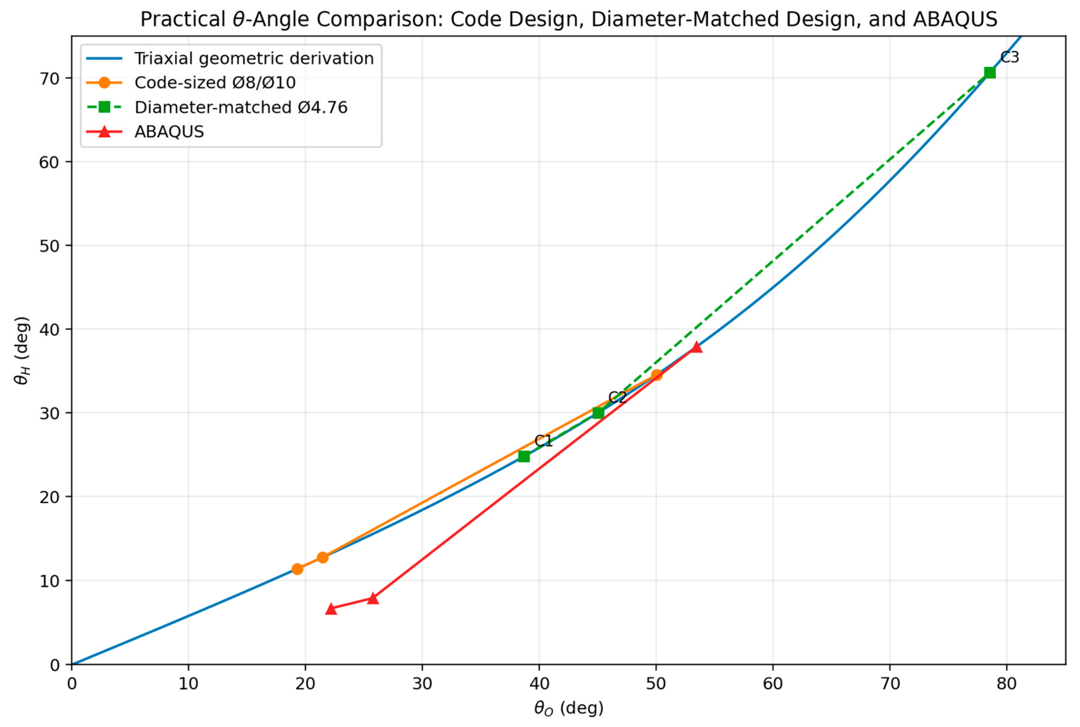
Three representative cases from the original numerical study are re-evaluated using two complementary routes. The first route uses practical conventional bar diameters. The second preserves the 4.76-mm bar diameter reported in the ABAQUS models and recalculates spacing from a prescribed steel area. The second route is a sensitivity/equivalence calculation, not a universal code-compliant flexural-bar solution.
11.1. Practical Comparison Route
| Case | h (mm) | w_u (kN/m²) | A_s,req (mm²/m) | Practical layout | A_s,prov (mm²/m) |
| 1 | 67 | 28 | 339 | Ø8@120 | 418.9 |
| 2 | 76 | 36 | 349 | Ø8@130 | 386.7 |
| 3 | 180 | 190 | 566 | Ø10@130 | 604.2 |
For a geometric comparison, an illustrative effective-depth convention d_code=h−25 mm is retained. This is a comparison assumption, not an ACI-prescribed effective-depth equation.
A_s,prov=(πφ²/4)(1000/s)
θ_O,code=atan(d_code/s_O)
θ_H,der=atan[tan(θ_O,code)/√3]
The resulting illustrative orthogonal angles are 19.29°, 21.42°, and 50.01°, with corresponding transformed triaxial values of 11.42°, 12.76°, and 34.54°. The label 'code-oriented' refers to the practical detailing context and not to a code-prescribed θ value.
11.2. FE-Diameter-Matched Sensitivity Route
A_b=π(4.76)²/4=17.80 mm²
s_matched=1000A_b/A_s,req
| Case | A_s,req (mm²/m) | Diameter | Equivalent spacing | θ_O,matched | θ_H,der |
| 1 | 339 | Ø4.76 | 52.5 mm | 38.66° | 24.79° |
| 2 | 349 | Ø4.76 | 51.0 mm | 45.01° | 30.01° |
| 3 | 566 | Ø4.76 | 31.4 mm | 78.53° | 70.64° |
The large change in θ_O between practical Ø8/Ø10 layouts and the diameter-matched Ø4.76 layouts is expected because bar diameter determines the number of bars required per metre to provide a specified steel area. A direct θ comparison between different bar diameters can therefore confound topology with reinforcement-density effects.
Figure 2.
Practical θ-angle comparison for conventional code-oriented layouts, diameter-matched Ø4.76 layouts, and ABAQUS reference configurations.
Figure 2.
Practical θ-angle comparison for conventional code-oriented layouts, diameter-matched Ø4.76 layouts, and ABAQUS reference configurations.
11.3. Comparison with the ABAQUS Configurations
The supplied source reports 1.83×1.83 m slabs, a 4.76-mm reinforcement diameter, the reinforcement arrangements, and the FE model formulation. It does not provide a verified numerical concrete cover or reinforcement-centroid z-coordinate. Therefore, d_FE=h−18.2 mm is retained only as a provisional legacy assumption for reproducing the existing angle comparison.
θ_O,FE=atan(d_FE/s_O,FE)
θ_H,FE=atan[√3d_FE/(2s_H,FE)]
| Case | θ_O,code | θ_O,matched | θ_O,FE | θ_H,der | θ_H,FE |
| 1 | 19.29° | 38.66° | 22.13° | 24.79° | 6.70° |
| 2 | 21.42° | 45.01° | 25.72° | 30.01° | 7.92° |
| 3 | 50.01° | 78.53° | 53.44° | 70.64° | 37.90° |
The code-oriented angle reflects a practical bar-size/spacing selection; the diameter-matched angle preserves the FE bar diameter while matching the calculated steel area; and the ABAQUS angle reflects the numerical arrangement used in the existing model set. These quantities should not be collapsed into a single 'true' θ.
11.4. Exploratory Intermediate Descriptor
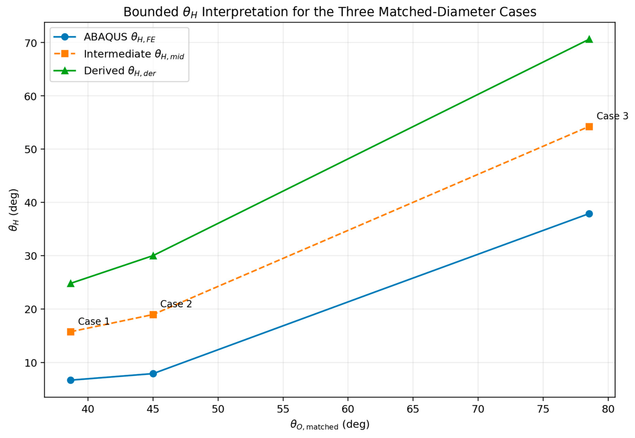
For descriptive calibration only, an intermediate descriptor may be defined as the arithmetic mean of the analytical and FE-derived triaxial angles:
θ_H,mid=(θ_H,der+θ_H,FE)/2
| Case | θ_H,der | θ_H,FE | θ_H,mid | θ_H,mid/θ_O,matched |
| 1 | 24.79° | 6.70° | 15.74° | 0.407 |
| 2 | 30.01° | 7.92° | 18.96° | 0.421 |
| 3 | 70.64° | 37.90° | 54.27° | 0.691 |
The mean ratio of approximately 0.51 is a descriptive statistic for these three cases only. It is not proposed as a universal design coefficient.
Figure 3.
Exploratory bounded interpretation of θ_H using analytical, ABAQUS, and intermediate values for the three matched-diameter cases.
Figure 3.
Exploratory bounded interpretation of θ_H using analytical, ABAQUS, and intermediate values for the three matched-diameter cases.
12. Proposed ABAQUS Verification Protocol
- Crack-direction extraction: obtain maximum principal tensile-strain directions at representative load levels and calculate the angular misalignment ψ with the nearest reinforcement family.
- Stress-trajectory extraction: use principal compressive-stress fields in genuine discontinuity regions to estimate θ_STM,FE independently of θ_d.
- Spacing sensitivity: vary s_h while controlling total steel, concrete properties, boundary conditions, and bar diameter, and track θ_d, cracking load, ultimate pressure, and deflection.
- Equal-steel comparison: compare orthogonal and triaxial slabs at equal total steel before drawing conclusions about topology.
- Confinement verification: extract local three-dimensional concrete stress states and reinforcement forces around representative nodes before assigning any effective confinement coefficient.
- Membrane verification: use displacement control to large deformation and extract reinforcement axial forces, edge reactions, membrane resultants, and θ_m.
- Mesh convergence: repeat representative models with at least three mesh densities and report changes in ultimate pressure and deflection.
- Material-input verification: document concrete tension-softening, damage evolution, fracture-energy assumptions, compressive response, and steel properties.
- Geometry verification: extract the actual reinforcement centroid and concrete cover from the ABAQUS input before treating θ_FE as a final quantitative reference.
- Energy verification: report concrete damage/plastic work, reinforcement internal work, and external work if a strain-energy interpretation is to be retained.
13. Discussion
The central result of the revised framework is a separation of geometric and mechanical roles. θ_d can be calculated directly from reinforcement spacing and nodal geometry, making it useful for screening load-transfer geometry and detailing. It does not, however, provide a unique prediction of ultimate slab pressure. θ_STM is associated with a selected compression-tension force path and should be evaluated where an STM description is mechanically appropriate. The orientation variables θ_i, φ, and ψ describe directional flexural and cracking behaviour, while θ_m belongs to the large-deflection membrane regime.
The new analytical framework clarifies why the triaxial topology can exhibit useful directional characteristics without requiring a claim of universally higher strength. The three-family projection identities produce an idealized isotropic steel-only stiffness measure and reduce the maximum crack-normal misalignment from 45° to 30°. These are topology-level geometric results. Their translation into crack control, stiffness, ductility, or ultimate strength requires nonlinear RC analysis and experimental verification.
The S8/S9 comparison is especially informative when its steel-density normalization is stated correctly. S9 is 25% of S8 in total steel density because S8 uses 60-mm orthogonal spacing while S9 uses 360-mm triaxial spacing. S9 is, however, 50% of the 120-mm orthogonal reference used in the same family of models. The reported ultimate pressures of 235 and 225 kN/m² therefore provide a numerical case study of similar FE capacity under substantially different steel densities, but they cannot by themselves establish a universal 50% steel-reduction rule.
The confinement and strain-energy sections are intentionally conservative. The topology provides a rational reason to investigate local three-dimensional restraint, but neither the Mander confinement equations nor the proposed effective confinement coefficients have been validated for a primary flexural triaxial slab mesh. Likewise, the energy decomposition is a useful hypothesis for designing the next FE study, not a demonstrated mechanism.
The practical application adds an important methodological control: retaining the FE bar diameter while recalculating spacing from a prescribed steel area demonstrates that part of the observed θ difference is caused by bar diameter and spacing rather than topology alone. This control should be retained in future numerical comparisons.
14. Limitations
- The geometric θ_d definition depends on the selected nodal pitch and effective depth; both quantities must be reported explicitly.
- The 25° reference belongs to STM terminology in the adopted code framework and should not be presented as a universal slab-mesh acceptance criterion.
- The 1.85d value is a research-derived geometric expression under the stated triaxial geometry.
- The idealized 1.5 moment factor and 0.75 stiffness factor are topology-level identities under specified normalization assumptions, not direct reinforced-concrete slab capacity predictions.
- The S1–S10 models are numerical calibration cases rather than independent physical experiments.
- The S8/S9 steel-density relation must be reported with a common reference; S9 is 75% lower than S8 but 50% of the orthogonal 120-mm reference.
- The diameter-matched Ø4.76 calculations are sensitivity/equivalence calculations and are not, by themselves, evidence of practical code compliance.
- The supplied ABAQUS source does not state a verified reinforcement-centroid z-coordinate or actual concrete cover; d_FE=h−18.2 mm therefore remains a provisional legacy assumption.
- The confinement interpretation is conceptual and requires direct FE or experimental calibration before any effective confinement coefficient is assigned.
- Direct ABAQUS extraction of θ_STM, crack directions, membrane forces, local stress states, energy components, and mesh convergence is still required before any new θ-based design limit or generalized reinforcement-reduction claim is proposed.
15. Conclusions
- The symbol θ should not be treated as a single universal angle in two-way reinforced-concrete slab analysis. At minimum, θ_STM, θ_d, reinforcement/yield-line orientation variables, and θ_m should be distinguished.
- The 0°/60°/120° arrangement is most accurately described as a planar triaxial triangular reinforcement network; the hexagonal cell is a geometric/topological representation rather than a literal honeycomb material model.
- For the adopted nodal-pitch definition, the orthogonal mesh has ℓ_o=s_o and the triaxial mesh has ℓ_h=2s_h/√3.
- Combining nodal-pitch geometry with the steel-density ratio gives tanθ_h=(R_h/√3)tanθ_o.
- The 1.85d spacing value is close to the triaxial geometric form associated with a 25° reference, but it is a research-derived geometric screening bound rather than an independent code spacing clause.
- The idealized three-family projection gives a 1.5 per-family moment factor; under equal-total-steel normalization this reduces to the same idealized normal plastic moment as the orthogonal system.
- The idealized steel-only triaxial stiffness measure is directionally isotropic under the adopted normalization, and the maximum crack-normal angular misalignment is reduced from 45° to 30°.
- S8 and S9 require careful steel-density normalization: S9 contains 25% of S8's total steel density, not 50%, while S9 contains 50% of the orthogonal 120-mm reference density.
- The reported S1–S10 FE pressures do not vary monotonically with θ_d. Consequently, θ_d should be used as a geometric/detailing/load-path descriptor rather than as a standalone strength criterion.
- The confinement and strain-energy interpretations should be treated as hypotheses until direct ABAQUS stress, strain, reinforcement-force, energy, and mesh-convergence evidence is obtained.
- Future work should independently extract θ_STM,FE from principal compression trajectories, crack directions, membrane forces, reinforcement centroids, local three-dimensional stress states, and mesh-convergence behaviour before any θ-based design limit or generalized reinforcement-reduction rule is proposed.
References
- Abdulridha, H. A. Triaxial hexagonal reinforcement in two-way reinforced-concrete slabs: a research and verification framework; revised research manuscript; 2026. [Google Scholar]
- Abdulridha, H. A. Finite element simulation of hexagonal arrangement reinforced concrete slabs using ABAQUS. unpublished source manuscript. 2023. [Google Scholar]
- Taylor, R.; Maher, D. R. H.; Hayes, B. Effect of the arrangement of reinforcement on the behaviour of reinforced concrete slabs. Mag. Concr. Res. 1966, vol. 18(no. 55), 85–94. [Google Scholar] [CrossRef]
- Juma’a, M. Nonlinear finite element analysis of the effect of reinforcement arrangement on the behaviour of reinforced concrete slabs. M.Sc. thesis, University of Basrah, Basrah, Iraq, 2013. [Google Scholar]
- Aoyagi, Y.; Yamada, K.; Takahashi, T. Strength and deformational characteristics of three-way reinforced concrete containment models subjected to lateral forces. Proc. SMiRT 6, Paper J4/6, 1981. [Google Scholar]
- Schlaich, J.; Schäfer, K.; Jennewein, M. Toward a consistent design of structural concrete. PCI J. 1987, vol. 32(no. 3), 74–150. [Google Scholar] [CrossRef]
- K. W. Johansen, Yield-Line Theory; Cement and Concrete Association: London, U.K., 1962.
- ACI Committee 318, Building Code Requirements for Structural Concrete (ACI 318-19) and Commentary; American Concrete Institute: Farmington Hills, MI, USA, 2019.
- EN 1992-1-1; Eurocode 2: Design of Concrete Structures—Part 1-1: General Rules and Rules for Buildings. CEN: Brussels, Belgium, 2004.
- Park, R.; Gamble, W. L. Reinforced Concrete Slabs, 2nd ed.; Wiley: New York, NY, USA, 2000. [Google Scholar]
- Park, R. Tensile membrane behaviour of uniformly loaded rectangular reinforced concrete slabs with fully restrained edges. Mag. Concr. Res. 1964, vol. 16(no. 46), 39–44. [Google Scholar] [CrossRef]
- Hayes, B. Allowing for membrane action in the plastic analysis of rectangular reinforced concrete slabs. Mag. Concr. Res. 1968, vol. 20(no. 65), 205–212. [Google Scholar] [CrossRef]
- Bailey, C. G. Membrane action of unrestrained lightly reinforced concrete slabs at large displacements. Eng. Struct. 2001, vol. 23(no. 5), 470–483. [Google Scholar] [CrossRef]
- Gibson, L. J.; Ashby, M. F. Cellular Solids: Structure and Properties, 2nd ed.; Cambridge University Press: Cambridge, U.K., 1997. [Google Scholar]
- Deshpande, V. S.; Ashby, M. F.; Fleck, N. A. Foam topology: bending versus stretching dominated architectures. Acta Mater. 2001, vol. 49(no. 6), 1035–1040. [Google Scholar] [CrossRef]
- Deshpande, V. S.; Fleck, N. A.; Ashby, M. F. Effective properties of the octet-truss lattice material. J. Mech. Phys. Solids 2001, vol. 49(no. 8), 1747–1769. [Google Scholar] [CrossRef]
- Maxwell, J. C. On reciprocal figures and diagrams of forces. Philos. Mag. vol. 27(no. 182), 250–261, 1864. [CrossRef]
- Mander, J. B.; Priestley, M. J. N.; Park, R. Theoretical stress-strain model for confined concrete. J. Struct. Eng. ASCE 1988, vol. 114(no. 8), 1804–1826. [Google Scholar] [CrossRef]
Figure 1.
Geometry and topology of the 0°/60°/120° triaxial reinforcement network, including the triangular-cell nodal pitch and hexagonal cell representation.
Figure 1.
Geometry and topology of the 0°/60°/120° triaxial reinforcement network, including the triangular-cell nodal pitch and hexagonal cell representation.
Disclaimer/Publisher’s Note: The statements, opinions and data contained in all publications are solely those of the individual author(s) and contributor(s) and not of MDPI and/or the editor(s). MDPI and/or the editor(s) disclaim responsibility for any injury to people or property resulting from any ideas, methods, instructions or products referred to in the content. |
© 2026 by the authors. Licensee MDPI, Basel, Switzerland. This article is an open access article distributed under the terms and conditions of the Creative Commons Attribution (CC BY) license (http://creativecommons.org/licenses/by/4.0/).
Copyright: This open access article is published under a Creative Commons CC BY 4.0 license, which permit the free download, distribution, and reuse, provided that the author and preprint are cited in any reuse.