

Submitted:
17 September 2026
Posted:
18 September 2026
You are already at the latest version
Abstract
Reverse parking of a vehicle with trailer is a challenging task to complete for human drivers due to its articulated structure, unstable reverse-motion behaviors and unintuitive steering responses. This paper proposes a compact, trailer-centric nonlinear model predictive control (NMPC)-based automation routine that integrates local motion generation and feedback control into a single receding-horizon framework, without requiring a separately planned reference path or a dedicated path-tracking controller. The trailer unit is represented as a virtual standalone vehicle, and its motion requirements are mapped to the vehicle unit inputs via inverse kinematics. This allows trajectory prediction and tracking objective to be represented only with trailer states, hence reducing the dimensions of the horizon-stacked state and weighting matrices compared to using the full vehicle-trailer formulation. The proposed controller is implemented as a single-shooting nonlinear program (NLP) and supports a three-staged maneuver sequence to obtain an improved final parking configuration. Simulation results demonstrate successful vehicle-trailer parking maneuvers, while hardware-in-the-loop (HIL) results further illustrate that online NMPC computation times can remain within the real-time sampling deadline, indicating that the proposed NMPC framework can offer a practical receding-horizon automation routine for vehicle-trailer reverse parking tasks.
Keywords:
vehicle with trailer system
; reverse parking automation
; optimization and control
; autonomous driving
1. Introduction
The development of autonomous or automated vehicles has seen much progress in recent years [1,2,3]. One of the most important functions of such vehicles is being able to plan and track their own paths [4,5]. An extension of this function is the capability of a vehicle to complete path-planning and path-tracking operations with an attached trailer. Reverse parking is one of the most challenging maneuvers to complete for an autonomous or automated vehicle and the difficulty increases considerably in reverse parking of a vehicle with a trailer. The difficulty in this type of maneuver is caused by several reasons. Even for reverse parking of a vehicle alone, an understeer vehicle becomes oversteer when driven in reverse which is usually not a very serious problem as speeds in reverse maneuvering are relatively smaller. This is further complicated for a vehicle with a trailer as the vehicle needs to be steered in the opposite direction of the intended trailer heading which is intuitively difficult for inexperienced drivers, resulting in the need for advisory systems to aid drivers [6]. These differences may result in not being able to follow the desired path for the trailer and oscillatory behavior in reverse motion. Another challenge is the fact that to orientate the trailer the same way, different steering inputs at the vehicle will be required depending on the current system configuration. This motivates the research reported in this paper on automating the vehicle-trailer reverse parking process.
A suitable system model is typically required for the vehicle-trailer combination to automate its reverse parking maneuver. Existing vehicle-trailer models can generally be categorized as dynamic or kinematic. Dynamic models are typically more structurally detailed as they account for factors such as tire forces, lateral slips and inter-body coupling effects, and they can be derived using Newton-Euler approaches [7,8,9,10] or Euler-Lagrange methods [11,12,13]. Several studies have also compared dynamic models with different configurations and levels of fidelity [14,15]. Although dynamic models are valuable for various system dynamics analysis, their complexity is generally unnecessary for low-speed parking scenarios, where tire slip effects are very minimal. As a result, kinematic models based on geometric relationships and nonholonomic constraints are frequently adopted for low-speed motion control designs. These models are typically derived using either the instantaneous center of rotation [16] or kinematic constraint equations [17,18]. Generalized formulations for multi-trailer systems can also be found in existing literature [19].
Due to their multi-body structure, path-tracking control of vehicle-trailer systems is a challenging task, particularly in the reverse direction, where hitch angles may grow and lead to jackknifing behaviors. As a result, many existing approaches employ two-staged hierarchical control architectures, where a high-level controller generates an intermediate reference and a low-level controller synthesizes system control inputs. Examples include the generation and tracking of desired hitch angle references [20,21], curvature references [22], and tractor-trailer yaw rates [23]. Another variant of the two-staged architecture regards the last trailer unit in the vehicle-trailer system chain as a ‘virtual tractor’, where the steering actions required to properly orientate the last trailer unit are mapped to the steerable axle of the tractor unit through geometric relations [6,17,24,25]. A further extension of this concept is to introduce an additional ‘virtual tractor’ behind the last trailer unit in the system chain with its steering axle located at a path-tracking preview point during reverse motions [18]. Other path-tracking control formulations include distributed continuous time optimal control based on subsystem decomposition [26] and nonlinear model-reference control [27].
Many of the above-mentioned path-tracking controllers require separately-generated feasible reference paths to be planned first. Existing path-planning approaches can be roughly categorized as optimization-based, search or sampling-based, exact geometric-based and data-driven learning-based methods. Optimization-based path planners generate feasible paths by solving optimization problems that integrate system dynamics or kinematics, input limits and collision constraints. Examples include the cascade path-planning routine detailed in [28], the initial path-targeting optimization method elaborated in [29], and the Pontryagin’s Minimum Principle (PMP)-based optimal path-planning routine explained in [30]. Search-based and sampling-based methods approach path-planning tasks by exploring a discrete or sampled configuration space while enforcing vehicle-trailer system dynamics/kinematics. Examples of this type of approaches include [31] that presents a lattice-based path planner that utilizes optimization to generate kinematically feasible motion primitives, [32] that combines an exact motion planner with an RRT-based planner. Apart from the exact motion planner discussed in [32] that exploits differential flatness, exact geometric-based path-planner is also employed in [33], where feasible paths are constructed by concatenating simple path constructs such as rotations, translations, stretches and bends. More recent endeavors aim to leverage deep neural networks to tackle path-planning tasks, such as [34] that uses semi-supervised learning. Some alternative approaches include [35] that calculates the minimum parking space required for a tractor-trailer system to attempt parallel parking, and [36] that proposes a cooperative trajectory planning algorithm for tractor-trailer wheeled robots.
While numerous vehicle-trailer planning and control methods have been reported in the literature, many treat feasible path generation and path-tracking control as separate tasks. Comparatively, fewer studies integrate local motion generation and feedback control within a single receding-horizon framework, where a finite-horizon optimal control problem (OCP) is repeatedly solved using the updated system state. Even fewer studies report real-time HIL or experimental implementations of such receding-horizon formulations for vehicle-trailer reverse parking. These gaps motivate the present work, which develops a compact, trailer-centric nonlinear model predictive control (NMPC) framework, featuring receding-horizon mechanism, for integrated local motion generation and closed-loop control and evaluates it through simulation study and HIL experiment. The main contributions of this work are as follows:
1) An integrated NMPC framework is developed to achieve local motion planning and feedback control within a single receding-horizon optimization, eliminating the need for a separately-generated reference path or a dedicated path following controller.
2) The proposed optimization framework leverages inverse kinematics of the vehicle-trailer system to reduce the dimensions of the horizon-stacked state and weighting matrices, as the predicted trajectory and tracking target are expressed only with the trailer states instead of the full system states. It should be noted, however, that the decision variable size is unaffected.
3) The proposed formulation is validated through simulation and HIL experiments. The results demonstrate successful vehicle-trailer reverse parking maneuvers and show that the online NMPC computation time remains within the real-time controller sampling deadline.
The outline of the rest of this paper is as follows. Section II presents the kinematic vehicle-trailer model. Section III presents the inverse kinematic model of the vehicle-trailer system. Section IV develops the receding-horizon NMPC reverse parking controller. Section V introduces the optional forward repositioning maneuver. Section VI illustrates implementation results of simulation case study and HIL experiment. The paper ends with conclusions and future work.
2. Kinematic Vehicle-Trailer Model
For the purpose of automating vehicle-trailer reverse parking maneuvers, a kinematic model is an ideal choice to represent the vehicle-trailer system due to its simple formulation and applicability in low-speed scenarios, where parking maneuvers are typically carried out. This section aims to introduce a vehicle-trailer kinematic model adopting the following assumptions:
1) The trailer hitch is located behind the rear axle of the vehicle unit.
2) The trailer unit adopts a one-axle semi-trailer configuration, and its axle is not steerable and not driven.
3) The vehicle-trailer system features only one trailer.
4) The vehicle unit is rear-wheel-drive.
The schematic of this vehicle-trailer system is displayed in Figure 1, and the parameters of this model are listed in Table 1.
The vehicle-trailer kinematic model is constrained by tire no side slip condition, where the orientations of the tires in the system are aligned with the directions of their velocity vectors. This result stems from the assumption that tire deformations are minimal at low speeds, where parking maneuvers typically occur. The kinematic vehicle-trailer model is hence given by the three vehicle and three trailer state equations described in Equation (1) to (6):
In Equation (1) to (6), and are the coordinates of the vehicle rear axle center, is the vehicle yaw angle, and are the coordinates of the trailer axle center, and is the trailer yaw angle. is the magnitude of the vehicle rear axle center velocity and can be positive (forward motion) or negative (reverse motion). is the hitch angle between the vehicle and trailer orientations. The inputs of this kinematic model are the vehicle rear axle speed and vehicle front axle steer angle .
3. Inverse Kinematics
3.1. Inverse Kinematic Model
One of the main difficulties of vehicle-trailer reverse maneuvering is the presence of unintuitive yaw behaviors. As a result, it would be helpful to first regard the trailer as a standalone vehicle and calculate a ‘virtual’ steering angle at the trailer that would orientate it properly, before mapping this ‘virtual’ angle to the actual steer angle at the vehicle steerable axle. This mapping relationship between the ‘virtual’ steer angle at the trailer and the actual steer angle at the vehicle is the inverse kinematic model.
The inverse kinematic vehicle-trailer model under consideration is identical to the model illustrated in Figure 1 except for the addition of a ‘virtual’ steerable axle at the trailer hitch, as illustrated in Figure 2 that shows only the trailer part of the model to reduce visual clutter. With this virtual steerable axle, the trailer unit can be regarded as a standalone vehicle, and its ‘virtual’ steer angle is denoted as . The kinematic constraint at the trailer virtual steer axle results in trailer hitch velocity vector being aligned with the ‘virtual’ steer angle .
The inverse kinematic model uses the trailer axle center as the position refence point and is given by Equation (7) to (10):
Equations (7) and (8) represent the ‘desired’ yaw rates of the trailer and the vehicle, respectively, given a virtual steer angle . Equation (9) represents the mapping from vehicle rear axle center speed to trailer axle center speed given a virtual steer angle . Equation (10), on the other hand, is the mapping equation from the virtual steer angle at the trailer hitch to the actual steer angle at the vehicle steerable (front) axle.
3.2. Inverse Kinematics Validation
A simulation study is performed to demonstrate the validity of the virtual to actual steering angle mapping of Equation (10). The simulation routine is illustrated in Figure 3. A ‘desired’ profile is first generated and fed into the inverse kinematics calculation block that invokes the actual-virtual steering angle mapping equation, and the resulting vehicle steer angle required is plugged into the kinematic vehicle-trailer model. An additional block is also included to calculate the ‘actual’ based on the outputs of the vehicle-trailer model, which is then compared with the ‘desired’ profile. The ‘actual’ calculation is given by Equation (11):
4. Reverse Parking Controller Design
In order to properly park a vehicle-trailer combination, one must accomplish both of the following two tasks: 1) generate a feasible path that leads the system from its initial states into the desired parking space; 2) generate a control sequence to follow the planned path. Model predictive control (MPC) is selected as the basis of the proposed controller, as it can handle both tasks with additional benefits as follows:
1) MPC provides closed-loop control laws since the optimization is re-run repeatedly with updated states.
2) MPC uses finite prediction horizon. While this may prevent the generation of a globally optimal solution, it is a suitable feature for reverse parking maneuvers that only involve short distance.
Given the nonlinear nature of the kinematic vehicle-trailer model, a nonlinear model predictive control (NMPC) formulation is introduced in this section.
4.1. Generalized Vehicle-Trailer Reverse Parking Problem
The vehicle-trailer reverse parking problem studied in this work is generalized as shown in Figure 5. The vehicle-trailer combination starts from a set of initial states and needs to dock into a desired parking space with designated position and orientation, where it is desirable for the trailer unit to reach zero states when the parking maneuver concludes. The X-Y coordinate system presented in Figure 5 is identical to that shown in Figure 1 and is initialized to the parking space before the path-planning procedure begins. It should be noted that this parking environment does not feature any dynamic or static obstacles, which is one of the limitations of this work that will be addressed in future work.
4.2. Nonlinear Model Predictive Control Formulation
In order to reduce the dimensions of the horizon-stacked state and weighting matrices in the optimization problem, path planning is only performed for the standalone trailer unit with a virtual steering axle at the trailer hitch, as shown in Figure 2. The planning solution is then propagated to the vehicle unit through the inverse kinematic model presented in Section III to generate the actual control inputs. As a result, the kinematic model used in this NMPC formulation only contains trailer position and orientation as its states and can be written as shown in Equation (12), where trailer axle speed and virtual steering angle at the trailer hitch serve as the inputs to be optimized.
Since the NMPC controller is implemented in discrete time, a discretization routine is applied to the continuous model described in Equation (12). Equation (13) provides an example of this step using the Euler-Forward method with a user-defined time step .
The cost function of the optimization problem is designed in a quadratic form as shown in Equation (14):
In Equation (14), is the prediction/control horizon and is user-defined, is the final predicted states at the end of the horizon, and are positive definite matrices that penalize the trailer states for not aligning with the desired final states, and is another positive definite matrix to penalize control efforts. As previously shown in Figure 5, the X-Y coordinate system origin is set as the desired final location for the trailer axle center with the X-axis being aligned with the final desired trailer orientation. As such, the path-planning goal for the trailer unit is to reach zero states (position and orientation) at the terminal time.
With the discrete kinematics and the cost function defined, the optimal control problem (OCP) can be formulated as shown in Equation (15), where the goal is to solve for a control sequence within input bounds that minimizes the cost function while complying with the kinematic model.
To solve the above OCP using a compact decision variable, a static single-shooting nonlinear programming (NLP) formulation is constructed, where only the stacked input sequence is treated as the decision variable. This can be done by incorporating the discrete trailer kinematics into the OCP, resulting in the single-shooting NLP as displayed in Equation (16). The horizon-stacked terms used in Equation (16) are defined in Equation (17) to (20).
The single-shooting NLP described in Equation (16) can be solved using available static optimization solvers such as [37]. Once the optimized trailer inputs (trailer axle speed and virtual steering angle at the trailer hitch) have been obtained, Equations (9) and (10) can be used to calculate the actual vehicle-trailer system inputs (vehicle rear axle speed and vehicle front axle steering angle) that would allow the trailer to follow the optimized path.
The NLP displayed in Equation (16) is solved in a receding-horizon manner. Specifically, at each NMPC controller iteration, the optimization routine is performed with the most recent trailer states, and only the first step in the optimized sequence , namely , will be applied to progress the system to its next time step, where the optimization routine will be run again using updated states.
The NMPC loop will be terminated if the trailer axle speed in the optimization solution becomes zero. Within the context of this formulation, zero speed choice indicates that additional motions can no longer improve the results any further, regardless of what steering input value is selected. This design choice contrasts with the standard optimization design where the final states of the system must satisfy a set of hard terminal constraints for the optimization routine to be considered successfully completed. The reason for this design choice is that depending on the initial conditions of the vehicle-trailer system, the vehicle-trailer combination may fail to reach the desired final states with reverse motions alone. This, however, does not mean that the overall parking maneuver is impossible, as pulling forward from the end point of this reversing stage might allow the system to obtain a more favorable configuration for additional backup stage(s) in the future. As a result, it is more suitable to set the terminal conditions of the NMPC reversing routine as ‘no further improvements possible’ instead of ‘target states reached’. The forward repositioning stage will be explained in more detail in later sections.
The NMPC approach described in this section is closed-loop in the sense that the optimization problem is repeatedly solved using updated system states. This receding-horizon mechanism allows the controller to compensate for model mismatches, disturbances, and other unforeseen errors by continuously correcting the optimization results using the most up-to-date trailer states. An additional benefit of this closed-loop characteristic is that this NMPC controller can serve as a standalone module by jointly performing local motion planning and control. This is in contrast with some other path-planning approaches such as Hybrid A*, which typically generate a kinematically feasible reference path that must then be followed by a separate path-tracking controller.
4.3. Input Constraints
Since the control inputs generated by the NMPC routine described above are virtual inputs for the trailer unit, the input constraints and , which are the upper and lower bounds of trailer axle speed and virtual steering angle, should be designed with care. The trailer speed constraints can be set somewhat freely, as the vehicle is most likely able to deliver the speed required for the maneuver considering its low-speed nature. The virtual steering limits, however, must be designed such that its virtual-actual steering angle mapping under the current hitch angle will not yield an actual steering angle that is unfeasible for the vehicle front axle. At the same time, the virtual steering angle will require its own feasible value range so that it can ensure reasonable trailer orientation behaviors. This subsection hence aims to provide some design details for the virtual steering angle constraints ( and ).
If we set the vehicle front wheel steering angle range as , then the mapping relationship from to , described in Equation (21), can be used to generate the mapped upper and lower bounds of the virtual steering angle, denoted as , under the current hitch angle.
If we further define the upper and lower bounds of the virtual steering angle that guarantee reasonable trailer orientation behaviors as , then the virtual steering input constraints ( and elements in and ) can be defined as shown in Equation (22):
This virtual steering constraint setting can only guarantee that the mapped actual steering angle does not exceed its limits at the current time step. As model prediction proceeds into future steps within the horizon, the hitch angle of the vehicle-trailer system is expected to change, hence potentially rendering the virtual steering limits invalid. Since only the first step of the optimized input sequence (corresponding to the current time step) will be applied, this setup can ensure that the actual vehicle steering angle always stays within its limits.
A simple numeric example is presented here to demonstrate the proposed input constraints design. Model parameter values listed in Table 2 are used. If one defines the current hitch angle of the vehicle-trailer system () and the vehicle front wheel steering angle range ( and ) to take the values listed in Table 3, then applying Equation (21) will yield . If one continues to define a reasonable set of trailer virtual steering angle limits ( and ) as shown in Table 3, one can apply Equation (22) to narrow down the range of admissible virtual steering to .
5. Forward Repositioning
In the occasion that backward motions of the vehicle-trailer combination alone cannot satisfactorily position the trailer into the parking space with proper orientation or if the final hitch angle of the system is too large, it is beneficial to pull forward first and then attempt reverse motions again. The forward repositioning maneuver has two main purposes: 1) obtain a more favorable system hitch angle so that it is easier to orientate the trailer unit as desired during further reverse motions; 2) open up some space for the system so that further backup maneuvers have room for adjustments.
While any additional backup maneuvers are to be handled with the proposed NMPC formulation detailed in Section IV, forward repositioning motion is handled with a pure-pursuit path-tracking controller that only applies to the vehicle. The forward path is designed as a straight line extending from the centerline of the desired parking space. Once the path is defined, the pure-pursuit controller can be designed as explained in detail in [38]. It should be remarked that the pure-pursuit controller here is designed to be applied to the vehicle unit in forward motions only, so the complications involving the trailer unit can be disregarded during the design process. The vehicle-trailer forward motion is terminated when both of the following conditions are met: 1) the hitch angle is smaller than a pre-defined angle threshold ; 2) the vehicle-trailer system is further away from the parking space than a pre-defined distance threshold . Once the forward repositioning maneuver is completed, the NMPC controller will be applied again to reverse the vehicle-trailer system into the desired parking space, hence finishing the three-staged parking maneuver.
6. Implementation Results
6.1. Simulation Case Study
Simulation studies are first conducted to test the efficacy of the proposed method. The value choices for various settings are listed in Table 4, where the geometric parameters listed, similar to those presented in Table 2, are chosen to represent a typical passenger vehicle-type towing unit and a small one-axle box trailer. Multiple cases with different initial conditions are studied to determine the adaptability of the proposed motion planning and control routine to numerous scenarios and system configurations, and this sub-section aims to provide the results of one scenario with an unfavorable initial condition to illustrate the benefits of the proposed three-staged routine.
This scenario of interest aims to replicate a parallel parking maneuver with a nonzero initial hitch angle. The results of the simulation are presented in Figure 6 and Figure 7. The maneuver is conducted in three stages. Stage 1 motion is performed with the proposed NMPC controller where the trailer unit is reversed close to the desired parking position, with cost function value continuously decreasing during the process. The algorithm chooses the highest trailer axle reverse speed for as long as possible, as the goal of each optimization loop is to get as close to the final position and orientation as possible. Stage 1 motion is concluded with the choice of zero trailer axle speed, as the NMPC routine can no longer reduce cost function value via further motions. Stage 2 motion is the forward repositioning maneuver completed by the pure-pursuit controller applied to the vehicle unit. The forward motion allows the vehicle-trailer system to obtain a much more favorable configuration and opens the space for further backward adjustments of the system. Following the forward repositioning maneuver, stage 3 motion is performed with the same NMPC controller. Thanks to the forward motion in stage 2, this stage requires much less trajectory adjustment as compared to stage 1. It can also be observed that the vehicle unit steering commands remain within the specified range for the entire duration of the parking maneuver, proving the effectiveness of the input constraint design. The effectiveness of the three-staged design can be further observed from the performance metrics recorded in Table 5, where the addition of stage 2 forward motion enables stage 3 motion to achieve a much smaller trailer distance error and trailer orientation error compared to stage 1 motion. Additionally, the terminal hitch angle at the end of stage 3 motion is also smaller than that at the end of stage 1 motion. While it is not one of the design objectives of the controller, a small terminal hitch angle is generally desirable for a vehicle-trailer system parking maneuver.
The cost weighing matrices Q, P and R listed in Table 4 have been tuned so that the NMPC reversing routine can achieve satisfactory performance. While this weight tuning process is mainly based on intuition and trial and error, some rules of thumb apply: 1) in Q and P matrices, trailer heading and Y-axis deviations are penalized more than X-axis deviations to encourage the system to reverse into the parking space without clipping into neighboring spaces; 2) in R matrix, nonzero steering input selections are penalized minimally; 3) in R matrix, nonzero speed input selections are not penalized as it is desirable to complete the reversing maneuver as quickly as possible.
To further demonstrate the effectiveness of this cost function weighing design, a simplified sensitivity analysis is performed. An alternative set of weighing matrices, denoted as , and , are first selected as shown in Table 6. The proposed NMPC controller is then applied with different combinations of modified and unmodified cost weightings, and the numeric results are recorded in Table 6. Since stage 3 initial conditions are dependent on the resetting effect of stage 2 forward motions, only stage 1 results are included for this analysis. It can be observed that introducing any modified cost weighting matrices that are not selected according to the rules of thumb causes varying extent of performance deterioration for the NMPC controller.
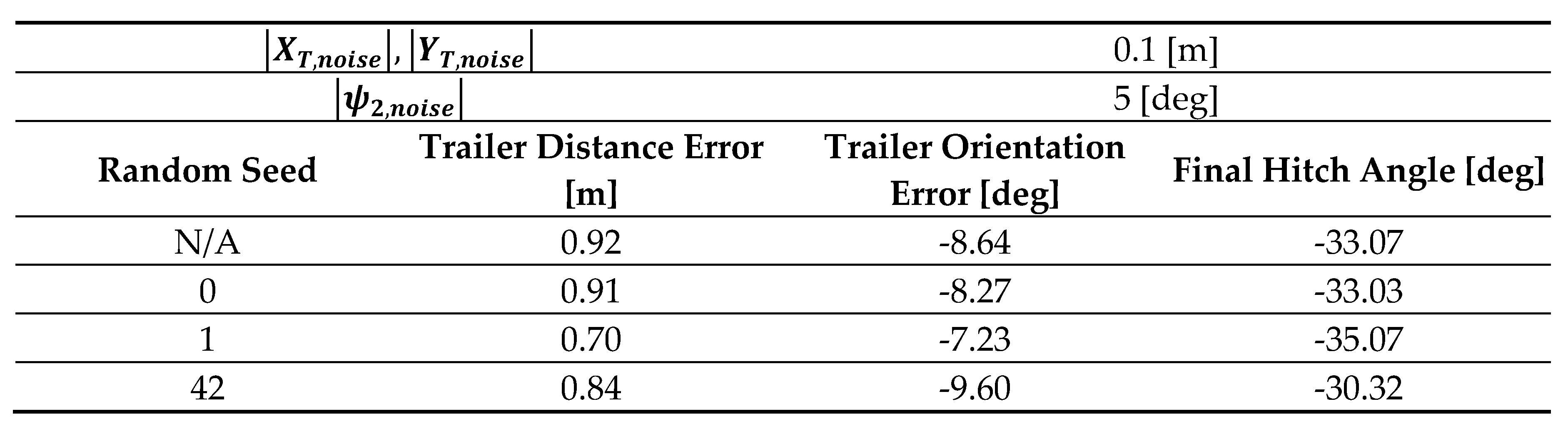
An additional set of simulation studies is performed to demonstrate the closed-loop performance of the proposed NMPC controller against disturbances such as sensor noises. The trailer states that serve as inputs of the NMPC solver are injected with sensor noises that apply to both the position and the heading. These noise signals are randomly generated within selected value ranges using a uniform distribution. For the same consideration as described in the sensitivity analysis above, only stage 1 results are analyzed in this study. Three random seeds are used for sensor noise generation, and their results are reported in Table 7. For comparison purposes, stage 1 results without any sensor noises being added are also included in Table 7 as the first row of data entries. It can be observed that thanks to the receding-horizon mechanism of the NMPC controller, the introduction of sensor noises does not cause significant changes to the path-planning and path-tracking performance.
6.2. Hardware-in-the-Loop (HIL) Implementation
While the simulation study verified the functionality of the proposed NMPC controller, HIL testing is required to evaluate the real-time implementation feasibility of the controller. The HIL setup shown in Figure 8 consists of a dSPACE SCALEXIO real-time target, a dSPACE MicroAutoBox II embedded PC, and a host computer. The SCALEXIO platform executes the vehicle-trailer plant model and serves as a surrogate for the physical system, while the NMPC routine is deployed on the MicroAutoBox II unit to facilitate real-time control. System states and control commands are exchanged between the two targets through CAN communication, and the host PC is used to coordinate the experiment with MATLAB/Simulink, dSPACE ConfigurationDesk and ControlDesk software.
The HIL experiment evaluates whether the NMPC controller is capable of real-time operation, specifically, whether NMPC optimizations can be completed within the controller sampling period. Additionally, while the simulated system plant does not reproduce every aspect of physical vehicle testing, the combination of embedded controller hardware, real-time execution, and CAN-based communication provides an intermediate validation step toward implementation on an actual vehicle-trailer platform.
It should be remarked that this HIL implementation study is focused on the proposed NMPC controller only. The optional forward repositioning maneuver is not separately evaluated in HIL since it is based on a pure-pursuit formulation, which is computationally simple and widely used in autonomous vehicle applications.
The results of the HIL test are displayed in Figure 9. The model parameters used in this test are identical to the value choices listed in Table 6, and another unfavorable version of the parallel parking maneuver is used in this case. It can be observed that the proposed NMPC-based routine is able to use vehicle unit steering inputs that are within limits to direct the vehicle-trailer system to the desired terminal position and orientation despite the less than desirable initial pose. The routine also proves itself to be adequate for online operations, as it can be carried out in the MicroAutoBox unit without triggering task overrun. Specifically, the computational time for a single NMPC iteration varies between 0.4167 msec to 2.83 msec, while both the SCALEXIO target and the MicroAutoBox PC run with a sampling interval of 0.1 sec.
7. Conclusion and Future Work
This paper developed a trailer-centric NMPC framework for vehicle-trailer reverse parking automation. The method integrates local motion generation and feedback control within a single receding-horizon optimization routine, hence eliminating the need for a separately generated reference path or a dedicated path-tracking controller. Through inverse kinematics, the trailer unit is regarded as a virtual standalone vehicle, where its ‘virtual’ inputs are mapped to the actual vehicle unit inputs. This allows the predicted trajectory and tracking target to be expressed with only trailer states, hence reducing the dimensions of the horizon-stacked state and weighting matrices. A three-staged maneuver sequence was also introduced to improve the final parking configuration. Simulation and HIL results demonstrated successful parking maneuvers under the tested conditions and confirmed that the online NMPC computation time remained within the real-time controller sampling period, supporting the deployment feasibility of the proposed control framework within a real-time CAN-based architecture. Future work will address the limitations of the current approach by further extending it with the following: 1) integrate static and dynamic obstacle avoidance into the three-staged parking sequence; 2) integrate more detailed constraints into the NMPC framework; 3) validate the proposed formulation on a physical vehicle-trailer platform.
Author Contributions
Conceptualization, X.C., H.C., B.A.-G., L.G., B.L., P.J.R., D.Y., S.F. and J.H.; Methodology, X.C. and H.C.; Software, X.C. and H.C.; Validation, X.C. and H.C.; Formal analysis, X.C., H.C., B.A.-G., L.G., B.L., P.J.R., D.Y., S.F. and J.H.; Investigation, X.C., H.C., B.A.-G., L.G., B.L., P.J.R., D.Y., S.F. and J.H.; Resources, B.A.-G., L.G. and B.L.; Data curation, X.C., H.C., B.A.-G. and L.G.; Writing—original draft, X.C. and H.C.; Writing—review & editing, B.A.-G. and L.G.; Visualization, X.C., H.C., B.A.-G. and L.G.; Supervision, B.A.-G. and L.G.; Project administration, B.A.-G., L.G. and B.L.; Funding acquisition, B.A.-G., L.G. and B.L. All authors have read and agreed to the published version of the manuscript.
Funding
This research was supported in part by HATCI (Hyundai America Technical Center, Inc.).
Data Availability Statement
Data are contained within the article.
Acknowledgments
The Ohio State University authors would like to thank HATCI (Hyundai America Technical Center, Inc.) for supporting this work.
Conflicts of Interest
Authors Brian Link, Peter J. Richmond, Dokyung Yim, Shihong Fan and John Harber were employed by the company Hyundai America Technical Center, Inc. (HATCI). The remaining authors declare that the research was conducted in the absence of any commercial or financial relationships that could be construed as a potential conflict of interest.
References
- R. Hussain and S. Zeadally, “Autonomous Cars: Research Results, Issues, and Future Challenges,” IEEE Commun. Surv. Tutor., vol. 21, no. 2, pp. 1275–1313, 2019. [CrossRef]
- S. Y. Gelbal, B. A. Guvenc, and L. Guvenc, “SmartShuttle: a unified, scalable and replicable approach to connected and automated driving in a smart city,” in Proceedings of the 2nd International Workshop on Science of Smart City Operations and Platforms Engineering, in SCOPE ’17. New York, NY, USA: Association for Computing Machinery, Apr. 2017, pp. 57–62. [CrossRef]
- B. Wen, S. Y. Gelbal, B. A. Guvenc, and L. Guvenc, “Localization and Perception for Control and Decision-Making of a Low-Speed Autonomous Shuttle in a Campus Pilot Deployment,” SAE Int. J. Connect. Autom. Veh., vol. 1, no. 2, Art. no. 12-01-02–0003, Nov. 2018. [CrossRef]
- L. Claussmann, M. Revilloud, D. Gruyer, and S. Glaser, “A Review of Motion Planning for Highway Autonomous Driving,” IEEE Trans. Intell. Transp. Syst., vol. 21, no. 5, pp. 1826–1848, May 2020. [CrossRef]
- L. Guvenc, B. A. Guvenc, and M. T. Emirler, “Connected and Autonomous Vehicles,” in Internet of Things and Data Analytics Handbook, John Wiley & Sons, Ltd, 2017, pp. 581–595. [CrossRef]
- X. Cao et al., “Development of an Advisory System for Parking a Car with Trailer,” SAE International, Warrendale, PA, SAE Technical Paper 2025-01-8035, Apr. 2025. [CrossRef]
- F. Jindra, “Handling Characteristics of Tractor-Trailer Combinations,” SAE Trans., vol. 74, pp. 378–394, 1966.
- L. Alexander, M. Donath, M. Hennessey, V. Morellas, and C. Shankwitz, “A Lateral Dynamic Model of a Tractor-Trailer: Experimental Validation,” University of Minnesota Twin Cities, Minneapolis, MN, USA, Report Number 97-18, Nov. 1996.
- T. Lei, J. Wang, and Z. Yao, “Modelling and Stability Analysis of Articulated Vehicles,” Appl. Sci., vol. 11, no. 8, Art. no. 8, Jan. 2021. [CrossRef]
- Y. Gao, Y. Shen, T. Xu, W. Zhang, and L. Guvenc, “Oscillatory Yaw Motion Control for Hydraulic Power Steering Articulated Vehicles Considering the Influence of Varying Bulk Modulus,” IEEE Trans. Control Syst. Technol., vol. 27, no. 3, pp. 1284–1292, May 2019. [CrossRef]
- M. Luijten, “Lateral Dynamic Behaviour of Articulated Commercial Vehicles,” Thesis, Mechanical Engineering, Eindhoven University of Technology, Eindhoven, Netherlands, 2010.
- S. M. Wolfe, “Heavy Truck Modeling and Estimation for Vehicle-to-Vehicle Collision Avoidance Systems,” Dissertation, Mechanical Engineering, The Ohio State University, Columbus, OH, USA, 2014.
- B. Jia, H. Ren, Z. Yang, Z. Lou, and X. He, “Lateral Dynamic Model for Full-Size Semi-Trailer Container Trucks with Practical Evaluation,” in 2023 35th Chinese Control and Decision Conference (CCDC), May 2023, pp. 4295–4300. [CrossRef]
- Z. Brock, J. Nelson, and R. L. Hatton, “A Comparison of Lateral Dynamic Models for Tractor-Trailer Systems,” in 2019 IEEE Intelligent Vehicles Symposium (IV), Jun. 2019, pp. 2052–2059. [CrossRef]
- Y. He and J. Ren, “A Comparative Study of Car-Trailer Dynamics Models,” SAE Int. J. Passeng. Cars - Mech. Syst., vol. 6, no. 1, Art. no. 2013-01–0695, Apr. 2013. [CrossRef]
- M. Werling, P. Reinisch, M. Heidingsfeld, and K. Gresser, “Reversing the General One-Trailer System: Asymptotic Curvature Stabilization and Path Tracking,” IEEE Trans. Intell. Transp. Syst., vol. 15, no. 2, pp. 627–636, Apr. 2014. [CrossRef]
- R. Kusumakar, K. Kural, A. Tomar, and B. Pyman, “Autonomous Parking for Articulated Vehicles,” Thesis, HAN University of Applied Science, Nijmegen, Netherlands, 2017. [CrossRef]
- Adityen Sudhakaran, “Autonomous Parallel Parking of a Scaled Tractor Semi-Trailer,” Thesis, Mechanical Engineering, Eindhoven University of Technology, Eindhoven, Netherlands, 2018.
- P. Rouchon, M. Fliess, J. Levine, and P. Martin, “Flatness, motion planning and trailer systems,” in Proceedings of 32nd IEEE Conference on Decision and Control, Dec. 1993, pp. 2700–2705 vol.3. [CrossRef]
- C. Pradalier and K. Usher, “A simple and efficient control scheme to reverse a tractor-trailer system on a trajectory,” in Proceedings 2007 IEEE International Conference on Robotics and Automation, Apr. 2007, pp. 2208–2214. [CrossRef]
- C. Pradalier and K. Usher, “Experiments in Autonomous Reversing of a Tractor-Trailer System,” in Field and Service Robotics: Results of the 6th International Conference, C. Laugier and R. Siegwart, Eds., Berlin, Heidelberg: Springer, 2008, pp. 475–484. [CrossRef]
- Z. Leng and M. Minor, “A simple tractor-trailer backing control law for path following,” in 2010 IEEE/RSJ International Conference on Intelligent Robots and Systems, Oct. 2010, pp. 5538–5542. [CrossRef]
- Z. Li, H. Cheng, J. Ma, and H. Zhou, “Research on Parking Control of Semi-trailer Truck,” in 2020 4th CAA International Conference on Vehicular Control and Intelligence (CVCI), Dec. 2020, pp. 424–429. [CrossRef]
- Tomar et al., “Path following bi-directional controller for articulated vehicles,” Proceedings of the HVTT15, 2018.
- J. Morales, A. Mandow, J. L. Martinez, J. L. Martínez, and A. J. García-Cerezo, “Driver assistance system for backward maneuvers in passive multi-trailer vehicles,” in 2012 IEEE/RSJ International Conference on Intelligent Robots and Systems, Oct. 2012, pp. 4853–4858. [CrossRef]
- E. Kayacan, E. Kayacan, H. Ramon, and W. Saeys, “Distributed nonlinear model predictive control of an autonomous tractor–trailer system,” Mechatronics, vol. 24, no. 8, pp. 926–933, Dec. 2014. [CrossRef]
- Y. Sklyarenko, F. Schreiber, and W. Schumacher, “Maneuvering assistant for truck and trailer combinations with arbitrary trailer hitching,” in 2013 IEEE International Conference on Mechatronics (ICM), Feb. 2013, pp. 774–779. [CrossRef]
- C. Manav and I. Lazoglu, “A Novel Cascade Path Planning Algorithm for Autonomous Truck-Trailer Parking,” IEEE Trans. Intell. Transp. Syst., vol. 23, no. 7, pp. 6821–6835, Jul. 2022. [CrossRef]
- P. Zips, M. Böck, and A. Kugi, “An optimisation-based path planner for truck-trailer systems with driving direction changes,” in 2015 IEEE International Conference on Robotics and Automation (ICRA), May 2015, pp. 630–636. [CrossRef]
- Mohamed, J. Ren, H. Lang, and M. El-Gindy, “Optimal collision free path planning for an autonomous articulated vehicle with two trailers,” in 2017 IEEE International Conference on Industrial Technology (ICIT), Mar. 2017, pp. 860–865. [CrossRef]
- Ljungqvist, N. Evestedt, D. Axehill, M. Cirillo, and H. Pettersson, “A path planning and path-following control framework for a general 2-trailer with a car-like tractor,” J. Field Robot., vol. 36, no. 8, pp. 1345–1377, 2019. [CrossRef]
- K. Kvarnfors, “Motion Planning for Parking a Truck and Trailer System,” Thesis, School of Electrical Engineering and Computer Science, KTH Royal Institute of Technology, Stockholm, Sweden, 2019.
- P. Svestka and J. Vleugels, “Exact motion planning for tractor-trailer robots,” in Proceedings of 1995 IEEE International Conference on Robotics and Automation, May 1995, pp. 2445–2450 vol.3. [CrossRef]
- X. Zhang, J. Eck, and F. Lotz, “A Path Planning Approach for Tractor-Trailer System based on Semi-Supervised Learning,” in 2022 IEEE 25th International Conference on Intelligent Transportation Systems (ITSC), Oct. 2022, pp. 3549–3555. [CrossRef]
- D. Zobel, E. Balcerak, and T. Weidenfeller, “Minimum Parking Maneuvers for Articulated Vehicles with One-Axle Trailers,” in Robotics and Vision 2006 9th International Conference on Control, Automation, Dec. 2006, pp. 1–6. [CrossRef]
- G. Lei and Y. Zheng, “Research on Cooperative Trajectory Planning Algorithm Based on Tractor-Trailer Wheeled Robot,” IEEE Access, vol. 10, pp. 64209–64221, 2022. [CrossRef]
- The MathWorks, Inc., “fmincon - Find minimum of constrained nonlinear multivariable function - MATLAB.” Website. [Online]. Available: https://www.mathworks.com/help/optim/ug/fmincon.html.
- L. Guvenc, B. Aksun-Guvenc, S. Zhu, and S. Y. Gelbal, Autonomous Road Vehicle Path Planning and Tracking Control. John Wiley & Sons, 2021.
Figure 1.
Kinematic vehicle-trailer model with one trailer.
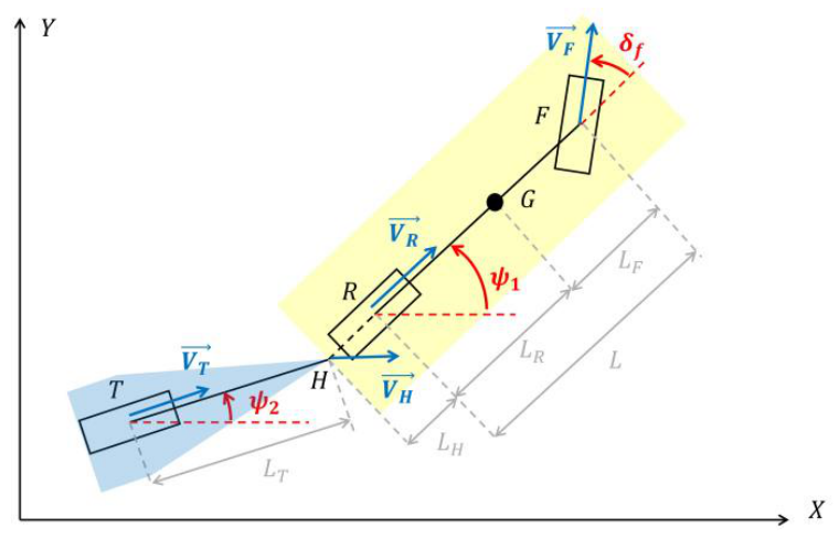
Figure 2.
Inverse kinematic vehicle-trailer model: trailer part.
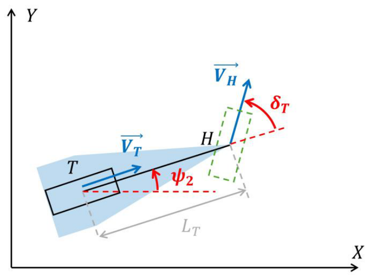
Figure 3.
Inverse kinematic simulation study model.
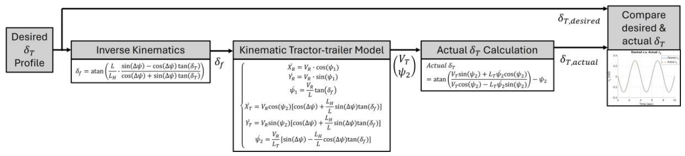
Figure 4.
Desired virtual steer angle tracking performance for trailer hitch behind vehicle rear axle in reverse motion.
Figure 4.
Desired virtual steer angle tracking performance for trailer hitch behind vehicle rear axle in reverse motion.
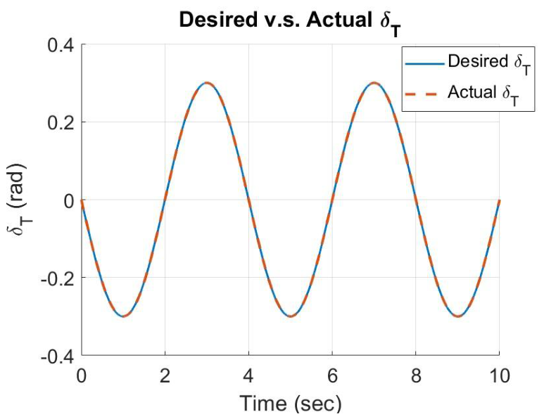
Figure 5.
A generalization of vehicle-trailer system reverse parking problem setup.
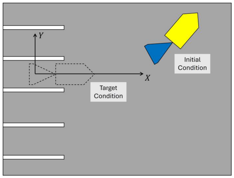
Figure 6.
Simulation results part 1: (a) Stage 1 motion; (b) Stage 2 motion; (c) Stage 3 motion; (d) Tractor-trailer overall (stage 1-3) trajectory; € Tractor vehicle overall (stage 1-3) inputs history; (f) Tractor-trailer overall (stage 1-3) hitch angle history.Figure 7. Simulation results part 2: (a) Stage 1 motion cost function history and trailer virtual inputs history; (b) Stage 1 motion trailer trajectory and trailer orientation history (c) Stage 3 motion cost function history and trailer virtual inputs history; (d) Stage 3 motion trailer trajectory and trailer orientation history.
Figure 6.
Simulation results part 1: (a) Stage 1 motion; (b) Stage 2 motion; (c) Stage 3 motion; (d) Tractor-trailer overall (stage 1-3) trajectory; € Tractor vehicle overall (stage 1-3) inputs history; (f) Tractor-trailer overall (stage 1-3) hitch angle history.Figure 7. Simulation results part 2: (a) Stage 1 motion cost function history and trailer virtual inputs history; (b) Stage 1 motion trailer trajectory and trailer orientation history (c) Stage 3 motion cost function history and trailer virtual inputs history; (d) Stage 3 motion trailer trajectory and trailer orientation history.
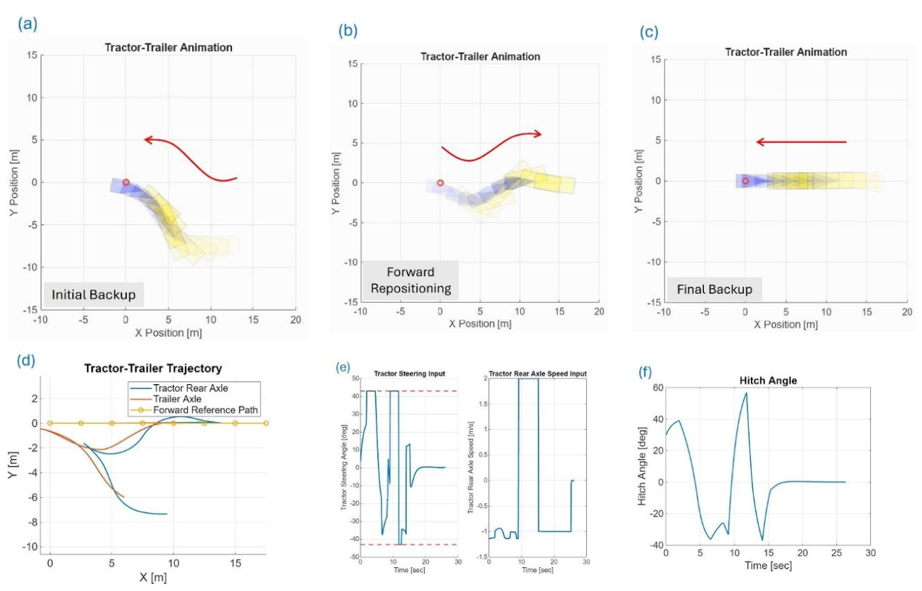
Figure 7.
Simulation results part 2: (a) Stage 1 motion cost function history and trailer virtual inputs history; (b)
Stage 1 motion trailer trajectory and trailer orientation history (c) Stage 3 motion cost function history and trailer
virtual inputs history; (d) Stage 3 motion trailer trajectory and trailer orientation history.
Figure 7.
Simulation results part 2: (a) Stage 1 motion cost function history and trailer virtual inputs history; (b)
Stage 1 motion trailer trajectory and trailer orientation history (c) Stage 3 motion cost function history and trailer
virtual inputs history; (d) Stage 3 motion trailer trajectory and trailer orientation history.
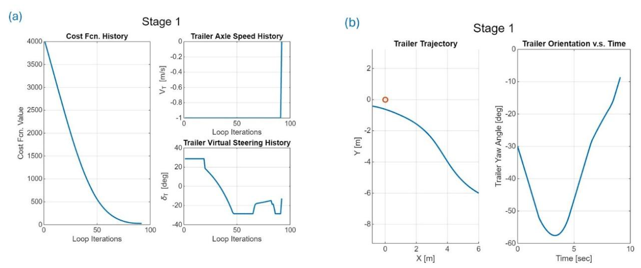
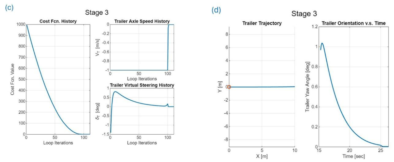
Figure 8.
(a) HIL architecture and information flowchart; (b) HIL simulator layout.
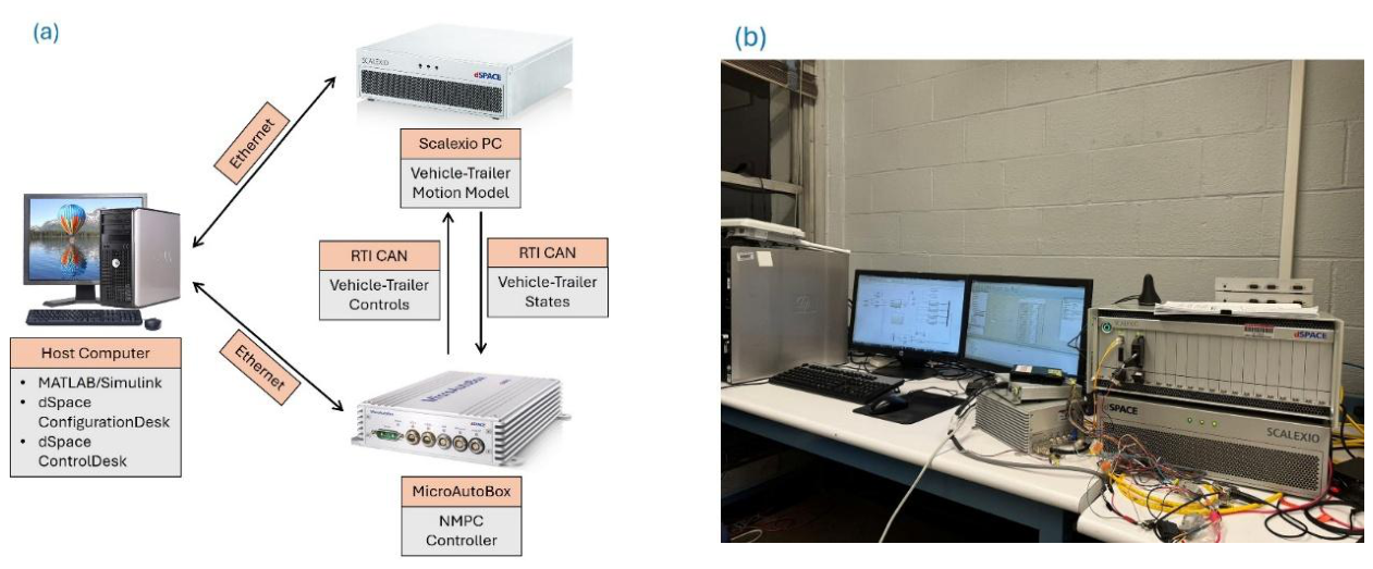
Figure 9.
HIL results: (a) NMPC reverse motion; (b) Vehicle-trailer trajectory; (c) Tractor vehicle input history; (d) Hitch angle history.
Figure 9.
HIL results: (a) NMPC reverse motion; (b) Vehicle-trailer trajectory; (c) Tractor vehicle input history; (d) Hitch angle history.
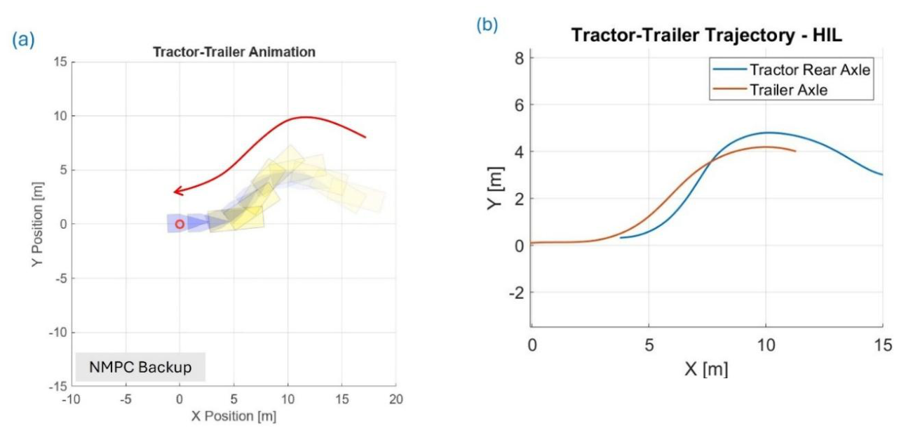
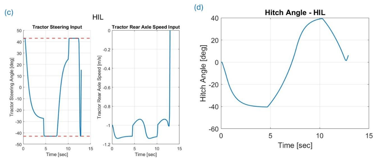

Table 1.
Parameters of Kinematic Vehicle-Trailer Model.
| Model Parameter | Explanation |
| Wheelbase of the tractor vehicle (car, SUV or pickup truck) | |
| Distance between vehicle center of gravity G and front axle | |
| Distance between vehicle center of gravity G and rear axle | |
| Distance between vehicle rear axle and trailer hitch joint | |
| Distance between trailer axle and trailer hitch joint | |
| Vehicle front wheel steer angle | |
| Vehicle yaw angle | |
| Trailer yaw angle | |
| Vehicle front axle velocity | |
| Vehicle rear axle velocity | |
| Trailer hitch velocity | |
| Trailer axle velocity |
Table 2.
Parameter Value Choices for Inverse Kinematics Simulation Study.
| Model Parameter | Value Choice |
| 3 [m] | |
| 1 [m] (passenger vehicle) | |
| 2.5 [m] | |
| -1 [m/s] (backward motion) |
Table 3.
Parameter Value Choices for Input Constraints Design Numeric Example.
| Parameter | Value Choice |
| 0.26 [rad] = 15 [deg] | |
| [-0.75,0.75] [rad] = [-42.97, 42.97] [deg] | |
| [-0.5,0.5] [rad] = [-28.65, 28.65] [deg] |
Table 4.
Simulation Case Study Value Choices.
| Parameter | Value Choice |
| 2.90 [m] | |
| 1.16 [m] (passenger vehicle) | |
| 2.69 [m] | |
| 0.1 [sec] | |
| 10 | |
| [-1, 0] [m/sec] | |
| [-0.75, 0.75] [rad] = [-42.97, 42.97] [deg] | |
| [-0.5, 0.5] [rad] = [-28.65, 28.65] [deg] | |
| 0.1 [rad] | |
| 7.5 [m] |
Table 5.
Simulation Case Study Numeric Results.
| Trailer Distance Error [m] | Trailer Orientation Error [deg] | Final Hitch Angle [deg] | |
| Stage 1 | 0.920 | -8.64 | -33.07 |
| Stage 3 | 0.00045 | 0.0044 | 0.096 |
Table 6.
Sensitivity Analysis Numeric Results.
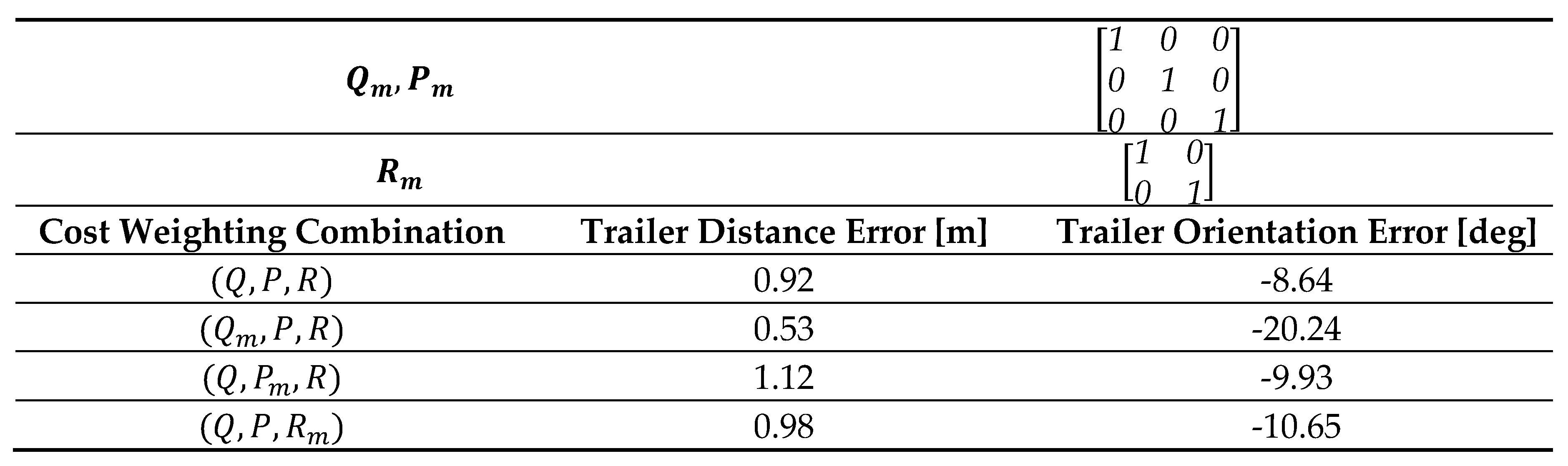 |
Table 7.
Sensor Noise Analysis Numeric Results.
 |
Disclaimer/Publisher’s Note: The statements, opinions and data contained in all publications are solely those of the individual author(s) and contributor(s) and not of MDPI and/or the editor(s). MDPI and/or the editor(s) disclaim responsibility for any injury to people or property resulting from any ideas, methods, instructions or products referred to in the content. |
© 2026 by the authors. Licensee MDPI, Basel, Switzerland. This article is an open access article distributed under the terms and conditions of the Creative Commons Attribution (CC BY) license (http://creativecommons.org/licenses/by/4.0/).
Copyright: This open access article is published under a Creative Commons CC BY 4.0 license, which permit the free download, distribution, and reuse, provided that the author and preprint are cited in any reuse.