

Submitted:
07 September 2026
Posted:
16 September 2026
You are already at the latest version
Abstract
This study investigates the role of shots on shot peening of austenitic steel AISI 304 as a function of shot peening cycles when the conventional steel shots are compared with the ceramic ones. The surface state is analysed in terms of dislocation density, stress state, and the phase transformation of the metastable paramagnetic austenite into the ferromagnetic strain-induced martensite. The sharp transition in magnetic state is monitored via Barkhausen noise emission. It was found that the height of the surface irregularities is nearly unaffected by the number of shot peening cycles and by the different shots. On the other hand, an increasing number of shot peening cycles leads to greater surface damage, as evidenced by the strain-induced martensite fraction and dislocation density. The use of steel shots results in greater microstructural alterations at greater penetration depths due to their higher mass and lower shot velocity. In contrast, ceramic shots produce a higher amplitude of surface stress. Barkhausen noise emission from the steel shots is stronger, which is linked to the higher fraction of strain-induced martensite, especially in the deeper regions. The application of steel shots can initiate and accelerate surface corrosion due to shot contamination, in contrast to the unaffected corrosion resistance of ceramic shots.
Keywords:
shot peening
; microstructure
; strain induced martensite
; austenite
; Barkhausen noise
1. Introduction
Shot peening (SP) is a well-known process for surface hardening in which the bombarded body absorbs the high kinetic energy of shots. The local stresses in the region of impact easily exceed the yield strength of metal bodies, and severe plastic deformation hardens the surface. This process is commonly used to obtain increased dislocation density and generate compressive stresses, thereby improving surface resistance to cyclic loading [1,2,3]. SP can be performed in various ways, with the degree of surface hardening customised by the optimised number of cycles, shot size, shot kinetic energy, etc. [4,5]. On the other hand, SP usually increases the height of surface irregularities, which can compensate for the effect of surface hardening with respect to the fatigue limit of components. SP can also be combined with other processes, such as laser processing and preliminary peening, due to their superimposed positive contributions to the surface state [6,7].
Austenitic steels are outstanding materials that combine high toughness with excellent corrosion resistance and low yield strength. For this reason, these materials can consume a large amount of deformation energy, and, after SP hardening, the surface can be combined with a soft core. On the other hand, these materials are susceptible to strain-induced martensite (SIM) transformation when the paramagnetic fcc austenite is transformed into bcc ferromagnetic SIM. The degree of this phase transformation depends on the matrix chemistry, austenite grain size, loading mode, process temperature, process conditions, and other factors [8,9,10]. SIM nuclei are usually found at the intersections of austenite dislocations when different dislocation slip systems are activated [12,13,14]. The fraction of austenite stabilisers, competing with ferrite ones, strongly affects stacking fault energy and the predominant mechanism of plastic deformation [10,15,16]. Lower stacking fault energy favours the formation of SIM and medium-deformation twinning, whereas higher stacking fault energy favours dislocation slip [10].
The SP of austenitic steels has already been investigated from different points of view. Unal and Varol [6] reported the presence of a nano-grained structure in AISI 304 after severe SP, as well as deformation twinning of the matrix. Fargas et al. [17] analysed surface delamination in AISI 304 after SP, as well as the martensite fraction, under different regimes of this process. The authors reported increased surface roughness and the initiation of microcracks on the surface. Further studies investigated the role of sheet rolling direction on subsequent SP in terms of magnetic anisotropy, as well as the role of stainless steel strength on the height of surface irregularities [18,19]. These studies also employed electromagnetic Barkhausen noise (MBN) to monitor the phase transformation of austenite into SIM. The authors discussed the influence of the as-received microstructure on the depth microstructure gradient and on the magnetic interaction among neighbouring martensite islands. Kleber and Baroso [20] combined the SP of austenitic steel with tensile stress, correlating MBN with the depth of penetration of the SIM.
The MBN technique is based on measuring electromagnetic and/or acoustic pulses generated by domain walls (DWs) during their irreversible motion [21,22]. Therefore, this technique is used exclusively in the case of ferromagnetic bodies or those in which a paramagnetic matrix is replaced by a ferromagnetic one. The use of MBN for monitoring austenitic steels is a very sensitive tool for assessing the degree and specific nature of austenite phase transformation when ferromagnetic components are initiated by plastic deformation and/or thermal processing [23,24,25]. Formation of SIM in the parental austenite has already been reported when different loading modes were applied. Uniaxial tensile loading is used in pilot studies in this field [23,25] and can be contrasted with biaxial or multiaxial loading [18,19,24,26]. Initiation of the higher-dislocation slip system under more complex loading makes the formation of SIM easier due to a higher density of nucleation nuclei in the austenite. The study by Neslušan et al. [26] also discussed the role of SIM-preferential straining in rolling with integrated slip.
This study reports on the role of shots in SP, comparing conventional steel and ceramic shots in the phase stability of AISI 304. The different shot masses and the corresponding differences in shot velocity affect the surface, resulting in meaningful differences in SIM fraction and MBN response. MBN is a function of stress state [27,28,29] and microstructure expressed in a variety of terms [30,31,32]. This study provides deep insight into this topic, investigating SP in terms of complexity and discussing corrosion resistance as an important functional feature of stainless steels.
2. Materials and Methods
The experiments were carried out on AISI 304 (yield strength 311 ± 11 MPa, ultimate strength 705 ± 15 MPa, and elongation at break 91 ± 1.8%; see Figure 1a), received as a 3 mm thick sheet. The samples of length 60 mm (along the sheet rolling direction, RD) and 20 mm in width (along the sheet width, TD) were cut for SP. ND is the direction along the sample’s thickness.
The chemical composition of the as-received steel is indicated in Table 1, and the microstructure is depicted in Figure 1b. The microstructure is composed of equiaxed austenitic grains with a limited fraction of delta ferrite; see Figure 1b. SP was performed in the self-made device under the conditions listed in Table 2. SP was studied as a function of the number of cycles (2, 4, 6, and 8) and the shot type (conventional steel or ceramic), all with the same average diameter. The energy stored in the samples during SP is expressed in Almen intensity as listed in Table 3.
3D surface topography was visualised using a confocal microscope (ZEISS Axio Observer Z1, LSM 700) with a 405 nm laser wavelength and the Z-stack function. The scanned raw data were also filtered using the aforementioned software, and specific surface features associated with the height of surface irregularities were subsequently exported.
MBN was measured using the RollScan 350 device, operated with the MircoScan software (magnetising frequency 125 Hz sine profile and magnetic field strength ±9.87 kA · m−1, sensor S1-18-12-01, sampling frequency 6.4 MHz). The measured MBN signal was filtered using a bandpass filter (30 ÷ 1000 kHz), and the background noise, with an effective value of 29.56 mV, was subtracted from the MBN signal, following the methodology reported earlier [33]. MBN was measured along RD and TD. MBN refers to the effective value of the signal. The software also provides information about the MBN envelope, as well as extracted features such as PP (position of MBN envelope maxima in the magnetic field, usually linked to magnetic strength).
The microstructure of the subsurface deformed layer was analysed by electron backscatter diffraction (EBSD). The samples were cut, embedded in conductive resin, and mechanically polished down to a 50 nm alumina suspension. Subsequently, the measurement was performed using an EDAX EBSD camera integrated into a ZEISS Auriga compact scanning electron microscope (SEM). The analysis was performed in OIM TSL 9.0 software, and points with a confidence index CI<0.1 were excluded from the analysis.
The 57Fe Mössbauer spectra of the samples were collected at room temperature in the reflection and the CEMS (Conversion Electron Mössbauer Spectroscopy) arrangements using a constant-acceleration spectrometer equipped with a 57Co/Rh source. CEMS reading depth is about 200 nm.
Residual stresses after SP were determined from XRD diffraction patterns using the XRD technique (Proto iXRD Combo diffractometer, the average effective penetration depth ~5 μm, scanning angle ± 39 °, Bragg angle 156.4 °). The residual stress and dislocation density in SIM were measured using Cr Kα radiation, with shifts of the 211 reflection used to calculate them. Winholtz & Cohen method and X-ray elastic constants ½S2 = 5.75 TPa−1, S1 = −1.25 TPa−1 were applied. The residual stress and dislocation density in austenite were measured using Mn Kα radiation, with shifts of the 311 reflection used to calculate them. Winholtz & Cohen method and X-ray elastic constants ½S2 = 7.80 TPa−1, S1 = −1.20 TPa−1 were applied. The stress and dislocation density depth profiles were obtained by sequentially removing the layers via electrochemical removal.
Dislocation density in the austenite as well as SIM was calculated as follows [34]:
(m−2) (1)
where D is crystallite size obtained from equation (2)
(nm) (2)
where K is the constant (0.89), λ is the X-ray wavelength (2.291 Å for ferrite and 2.103 Å for austenite), β represents the width of the XRD pattern at the half of its maximum, whereas θ is the Bragg angle equal to 156 °.
3. Results of Experiments and Their Discussion
3.1. Height of Surface Irregularities
The local stresses during the shot impact easily exceed the yield strength of the shot-peened surface, especially when AISI 304 is employed. Plastic deformation extrudes the matrix from the impact points and generates the typical grater-like surface, in contrast to that after cold rolling; see Figure 2. The height of irregularities on the surface, expressed in terms of the primary profile parameter PSa, increases steeply in the early phases of the SP process (for 2 SP cycles) and then exhibits a subtle drop for higher numbers of SP cycles; see Figure 3a. Also, Figure 3b and PSz show that the surface is gently smoothed as repeated impacts lower the highest peaks on the surface. The steel and ceramic shots produce surfaces with quite similar PSa; see Figure 3a. However, the maximum distance between the deepest valley and the highest peak, expressed in terms of PSz, is greater for the ceramic shots; see Figure 3b. Parameter PSz also exhibits smoothing behaviour at the higher SP cycles.
3.2. XRD Measurements
The higher PSz values for the ceramic shots correlate with higher compressive stresses in austenite and SIM; see Figure 4. Furthermore, certain stress anisotropies in the steel shots (residual stresses in RD differ from those in TD) can be contrasted with nearly the same stresses in RD and TD. Residual stresses in the austenite are nearly unaffected at the higher SP cycles, see Figure 4a. On the other hand, the continuous drop in residual stresses in SIM for the ceramic shot contrasts with the saturation phase in the medium SP cycles, followed by a decreasing magnitude for the 8 SP cycles, as depicted in Figure 4b.
Such behaviour indicates that the energy consumed by the surface during bombardment attains the critical threshold. The dynamic recovery of the matrix can be observed beyond this threshold, and this behaviour more or less overlaps with the region of surface smoothing depicted in Figure 3. The dynamic recovery also results in a lower dislocation density in austenite for the steel shots compared with the ceramic ones; see Figure 5a. This figure also shows that the dislocation density in austenite increases with SP cycles, whereas fully unaffected behaviour is observed in SIM. On the other hand, the SIM fraction for the steel shots exhibits steep growth up to 4 SP cycles, followed by a subtle drop later (due to dynamic surface recovery), in contrast to the monotonous growth of the SIM fraction for the ceramic shots; see Figure 5b. Comparing Figure 4b and Figure 5b, one might find that the continuous increase in residual stresses for the ceramic shots can be linked to the monotonic growth of the SIM fraction. On the other hand, dynamic recovery in the case of steel shots reduces the amplitude of residual stresses, along with a subtle fall in the SIM fraction.
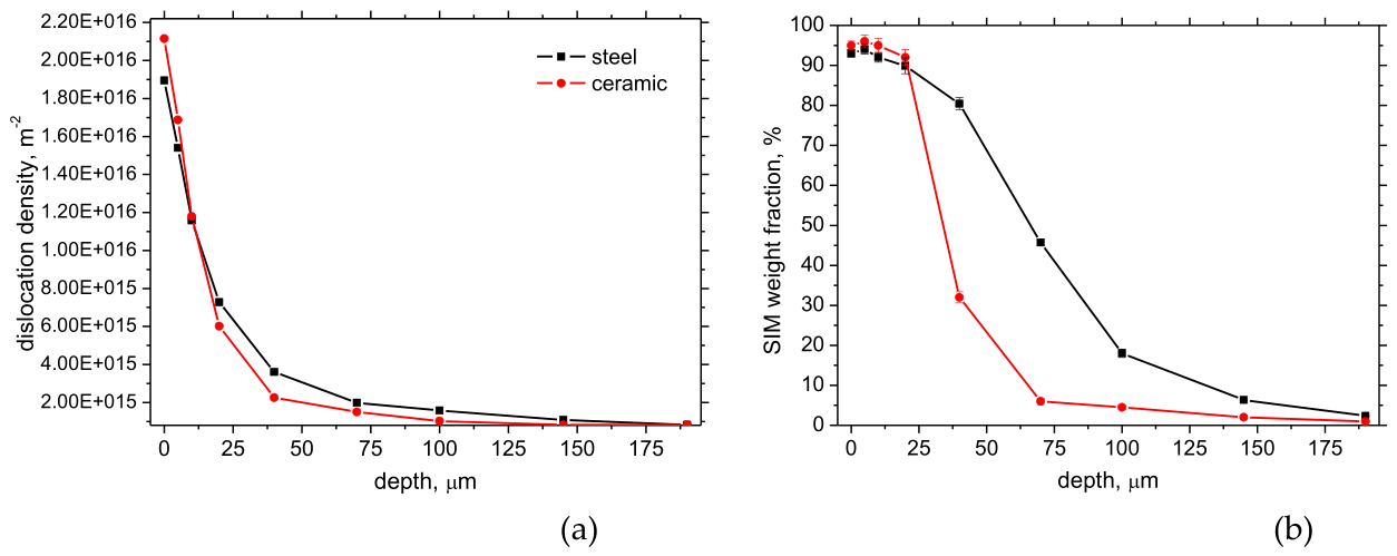
The big difference can be found with respect to the depth profiles of residual stress and SIM fraction. Residual stress in the SIM is more or less similar with depth below the surface, at about -725 ± 50 MPa for the steel shots and about -790 ± 45 Mpa for the ceramic shots. On the other hand, the slightly higher amplitude of the compressive residual stresses in the ceramic shots is offset by the lower penetration depth. The dislocation density δ for the steel shots is lower on the surface, at the expense of higher δ in the deeper regions; see Figure 7a. The SIM fraction in the near-surface region is slightly higher for the ceramic shots; see Figure 7b. However, the phase transformation penetrates much deeper in the steel shots, and the SIM fraction in the deeper regions is also higher than that produced by the ceramic shots. The δ in SIM is nearly unaffected with respect to shot type, as well as penetration depth, with density depicted in Figure 5a.
Figure 6.
Depth profile of residual stresses after 6 SP.
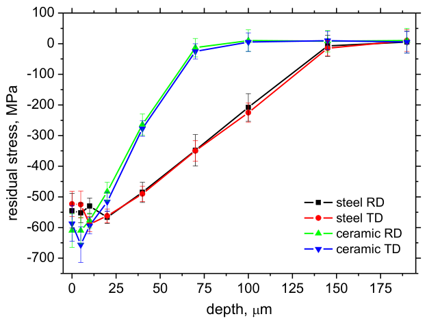
Figure 7.
Depth profile of dislocation density in austenite as well as SIM fraction after 6 SP cycles; (a) dislocation density in austenite, (b) SIM fraction.
Figure 7.
Depth profile of dislocation density in austenite as well as SIM fraction after 6 SP cycles; (a) dislocation density in austenite, (b) SIM fraction.
3.3. EBSD Observations and Mössbauer Spectroscopy
EBSD images depicted in Figure 8 confirm that the penetration depth of microstructural alterations in the steel shots is greater than that in the ceramic ones. IPF maps in the near-surface region exhibit extreme matrix fragmentation due to severe plastic deformation, which vanishes towards greater depth. Austenite neighbouring the SIM regions is of high dislocation density as contrasted against the less affected austenite at the depth, see KAM maps in Figure 8. The valuable degree of the phase transformation also confirms the Mössbauer spectra illustrated in Figure 9. However, the surface after application of the steel shots also contains the magnetic oxides as contrasted against the ceramic shot when only the non-ferromagnetic oxides of limited intensity can be obtained, see also the relative intensities in Table 4.
3.4. MBN Measurements
MBN originates from the SIM only, and its valuable growth is exclusively linked to the growing fraction of SIM, along with the SP cycles; see Figure 10 and Figure 11a. These figures also demonstrate that the differences in MBN with respect to RD and TD are mostly minor, and the higher MBN for the steel shots can be linked to the higher SIM fraction, especially in the deeper regions, since the estimated MBN sensing depth in this particular case is about 75 μm [35,36].
Figure 11.
MBN envelopes as a function of SP cycles; (a) steel shots - RD, (b) steel shots – TD, (c) ceramic shots - RD, (d) ceramic shots – TD.
Figure 11.
MBN envelopes as a function of SP cycles; (a) steel shots - RD, (b) steel shots – TD, (c) ceramic shots - RD, (d) ceramic shots – TD.
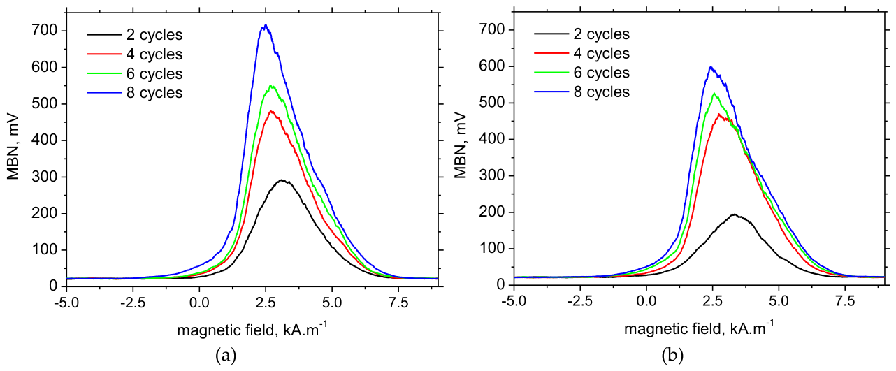
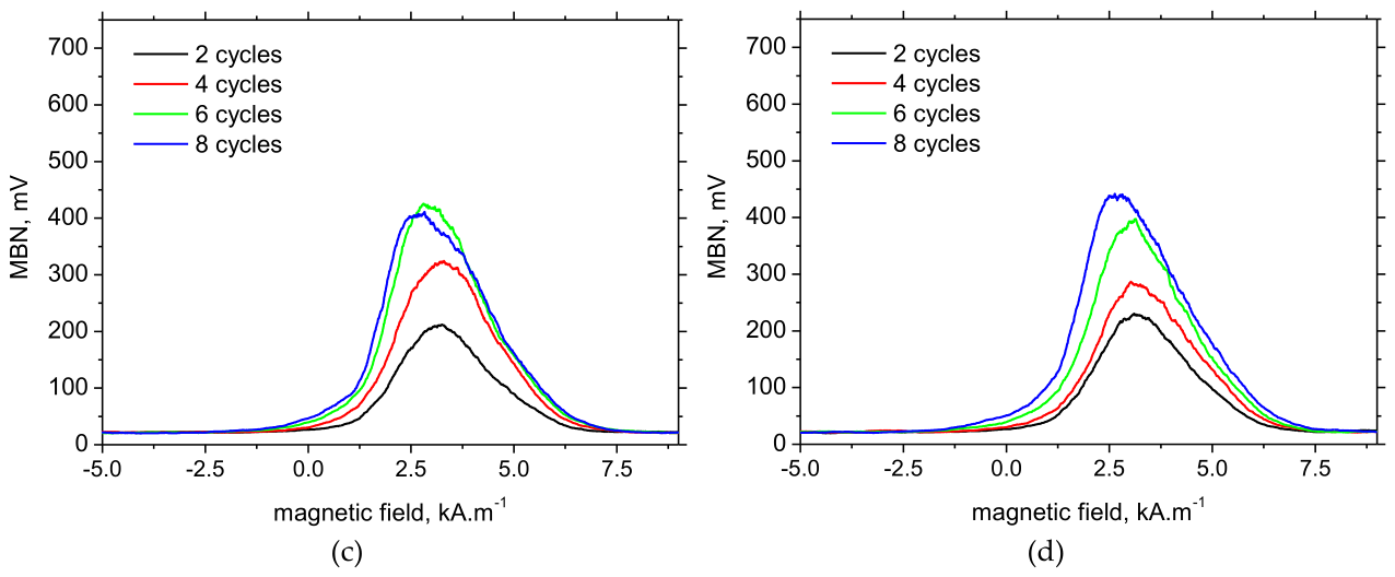
Figure 11b and Figure 12 also indicate that magnetic hardness decreases with SP despite the increasing SIM fraction. This behaviour is linked to magnetic exchange among the neighbouring SIM islands [18,19]. DWs occur in the form of avalanches [37,38], and magnetic communication with the neighbouring ferromagnetic region is important. When the SIM fraction is growing with SP cycles, the SIM island net is denser, and the distances among the neighbouring islands are shorter. For this reason, magnetic exchange is mediated more effectively when bridging gaps among the SIM islands is easier. Such behaviour also explains the higher PP and the corresponding magnetic hardness of the ceramic shots, as compared with the steel shots. The increasing SIM fraction makes the free path of DW motion longer and increases the number of DWs in motion, which in turn generates stronger MBN pulses detected on the free surface; see Figure 12a. The lower density of SIM islands for the ceramic shots, therefore, results in the absence of the stronger MBN above 1.4 V, as depicted in Figure 12b (and the corresponding lower MBN).
The aforementioned findings indicate different energy consumption processes during bombardment with shot and ceramic shots. The kinetic energy Ek of a shot can be calculated as follows:
(J) (3)
where m is a shot mass and v its velocity. When the mass is known, along with information about shot size and density (see Table 5), the shot velocity v is calculated using equation (4).
(m.s−1) (4)
where p is the air pressure, S is the cross-sectional area of the shot, and t is the time of a shot acceleration in the SP gun.
(s) (5)
where d is the acceleration distance in the SP gun.
Table 5 and Figure 13 indicate that the Ek is the same for both shots. The higher mass of the steel shots is compensated by their lower velocity and vice versa. The calculated kinetic energy Ek is composed of that consumed by the bombarded surface ΔEk for the alteration of stress state as well as microstructure and Ek-reb after a shot rebounding.
Ek-reb (J) (6)
The higher ceramic shot speed increases the strain rate of plastic deformation, which in turn contributes to a stronger elastic response at the expense of attenuated plasticity of the shot-peened body [39], especially in the deeper regions. The higher mass and the lower speed of the steel shots contribute to the higher ΔEk. For this reason, the alterations in stress state and microstructure penetrate deeper in the case of steel shots; see also Figure 13.
Figure 14 indicates a good correlation between MBN and Almen intensity, as well as the energy consumed by the matrix (Ek). On the one hand, Almen intensity reflects the role of austenite yielding and SIM formation, whereas MBN is exclusively linked to the SIM fraction. On the other hand, these processes are closely related when the austenite yielding is the preliminary phase of SIM nucleation [10,11,12,13]. Figure 14 also depicts the systematic shift between MBN and Almen when comparing the steel and ceramics shots. This shift should be related to the aforementioned differences in shot mass and velocity and the corresponding differences in the depth profiles depicted above.
4. Conclusions
The main findings of this study can be summarised as follows:
- -
- The use of ceramic shots introduces higher compressive stresses and a higher near-surface dislocation density, compared with steel shots.
- -
- The penetration depth at which valuable alterations in stress and microstructure can be observed is much greater for steel shots.
- -
- The kinetic energy of the steel and the ceramic shot is the same, but the ceramic shot’s lower mass compensates for its higher velocity.
- -
- MBN increases with SP cycles, and it is stronger for the steel shots due to the greater depth at which the significant SIM fraction is found.
- -
- Ferromagnetic oxides initiated by steel shots cannot be detected after SP using ceramic shots.
Author Contributions
Conceptualization, J.U. and M.N.; methodology, M.N. and M.P.; software, T.K.; validation, P.M. formal analysis, J.U.; investigation, J.U. M.P., P.M., T.K., M.N. and Z.F.; resources, M.N. and J.U.; data curation, M.P. and J.U.; writing—original draft preparation, M.P, M.N. and J.U.; writing—review and editing, X.X.; visualization, Z.F.; supervision, M.P.; project administration, M.P.; funding acquisition, M.N.
Funding
The authors gratefully acknowledge the financial support provided by VEGA project n. 1/0008/25 and KEGA project n. 005ŽU-4/2025.
Institutional Review Board Statement
Not applicable.
Informed Consent Statement
Not applicable.
Data Availability Statement
The raw data required to reproduce these findings cannot be shared easily due to technical limitations (some files are too large). However, authors can share the data on any individual request (please contact the corresponding author by the use of its mailing address).
Conflicts of Interest
The authors declare no conflict of interest.
References
- Zhang, H.; Zhang, J.; Chen, Y.; Zhang, J.; Dou, Y. Study on Residual Stress Relaxation Behaviour and Modelling of Shot-Peened TC4 Titanium Alloy, Metals 2026, 16, 482; https://doi.org/10.3390/met16050482 .
- Al-Zuhairi, A.; Lehner, P.; Blinn, B.; Smaga, M.; Flatter, J.; Beck, T.; Teutsch, R. Influence of Shot Peening on Selected Properties of the Surface and Subsurface Regions of Additively Manufactured 316L and AlSi10Mg, Metals 2025, 15, 856;. [CrossRef]
- Ahn, S.-H.; Kim, J.; Amanov, A. Improvement of Tribological Properties and Corrosion Resistance of AISI 4340M Steel by Shot Peening and Plating Technologies, Metals 2024, 14, 1037;. [CrossRef]
- Unal, O. Optimization of shot peening parameters by response surface methodology, Surf. Coating Technol. 2016, 305, 99-109;. [CrossRef]
- Segurado, E.; Belzunce, F.J.; Pariente, I.F. Effect of low intensity shot peening treatments applied with different types of shots on the fatigue performance of a high-strength steel, Surf. Coating Technol. 2018, 340, 25-35;. [CrossRef]
- Unal, O.; Varol, R. Surface severe plastic deformation of AISI 304 via conventional shot peening, severe shot peening and re-peening. Appl. Surf. Sci. 2015, 351, 289-295;. [CrossRef]
- Maleki, E.; Unal, O.; Kashyzadeh, K.R. Effect of conventional, severe, over and re-shot peening process on the fatigue behaviour of mild carbon steel, Surf. Coating Technol. 2018, 344, 62-74;. [CrossRef]
- Mine, Y.; Horita, Z.; Murakami Y. Effect of hydrogen on martensite formation in austenitic stainless steels in high-pressure torsion, Acta Mater. 2009, 57, 2993–3002;. [CrossRef]
- Shukla, S.; Patil, A.P. Effect of strain induced martensite reversal on the degree of sensitisation of metastable austenitic stainless steel, Proc. Struct. Integr. 2019, 14, 259-264;. [CrossRef]
- Sohrabi, M.J.; Naghizadeh, M.; Mirzadeh, H. Deformation-induced martensite in austenitic stainless steels: A review, Archiv. Civ. Mech. Eng. 2020, 20, 124;. [CrossRef]
- Mangonon, P.L.; Thomas, G. The martensite phases in 304 stainless steel. Metall. Trans. 1970, 1, 1577-1578;. [CrossRef]
- Aristeidakis, J.S.; Haidemenopoulos, G.N. Constitutive and transformation kinetics modeling of ε-, α -Martensite and mechanical twinning in steels containing austenite. Acta Mater. 2022, 228, 117757;. [CrossRef]
- Olson, G.B.; Cohen M. Kinetics of strain-induced martensitic nucleation. Metall Trans A. 1975, 6, 791–5;. [CrossRef]
- Brooks, J.W.; Loretto, M.H.; Smallman, R.E. In Situ Observations of the Formation of Martensite in Stainless Steel, Acta Metal. 1979, 27, 1829-1838;. [CrossRef]
- Fonstein, N. Advanced high strength sheet steels, first ed.; Springer International publishing, Switzerland, 2015;. [CrossRef]
- Berns, H.; Gavriljuk, V.; Riedner, S. High Interstitial Stainless Steels, first ed.; Springer: Berlin/Heidlberg, Germany, 2012. [CrossRef]
- Fargas, G.; Roa, J.J.; Mateo, A. Effect of shot peening on metastable austenitic stainless steels, Mater. Sci. Eng. A 2015, 641, 290-296;. [CrossRef]
- Neslušan, M.; Minárik, P.; Čep, R.; Uríček, J.; Trojan, K.; Ganev, N.; Trško, L. Barkhausen noise emission of AISI 304 stainless steel originating from strain induced martensite by shot peening, J. Mater. Res. Technol. 2022, 20, 748-762;. [CrossRef]
- Neslušan, M.; Minárik, P.; Čapek, J.; Kmječ, T.; Florková, Z.; Zgútová, K.; Trško, L. Shot peening of stainless steels and their monitoring via Barkhausen noise emission, J. Mater. Res. Technol. 2025, 38, 1129-1144;. [CrossRef]
- Kleber, X.; Barroso, S.P. Investigation of shot-peened austenitic stainless steel 304L by means of magnetic Barkhausen noise, Mater. Sci. Eng. A 2010, 527, 6046-6052;. [CrossRef]
- Jiles, D. Introduction to magnetizm and magnetic materials, 3rd ed.; Taylor & Francis Group: New York, USA, 2016.
- Chikazumi, S. Physics of ferromagnetizm, 2nd ed.; Oxford University Press, Oxford, 2005.
- Haušild, P.; Davydov, V.; Drahokoupil, J.; Landa, M.; Pilvin, P. Characterization of strain-induced martensitic transformation in a metastable stainless steel, Mater. Des. 2010, 31, 1821-1827;. [CrossRef]
- Haušild, P.; Kolařík, K.; Karlík, M. Characterization of strain-induced martensitic transformation in A301 stainless steel by Barkhausen noise measurement. Mater. Des. 2013, 44, 548-554; doi.org/10.1016/j.jmatdes.2012.08.058.
- Astudilo, M.R.N.; Nicolás, M.N.; Ruzzante, J.; Gómez, M.P.; Ferrari, G.C.; Padovese, L.R.; Pumarega, M.I.L. Correlation between martensitic phase transformation and magnetic Barkhausen noise of AISI 304 steel, Proc. Mater. Sci. 2015, 9, 435-443;. [CrossRef]
- Neslušan, M.; Bašťovanský, R.; Minárik, P.; Trojan, K.; Florková, Z.; Zgútová, K. Influence of slip ratio on the phase stability of austenitic steel AISI 304 during rolling contact wear, Friction 2026, 14/5, 9441203;. [CrossRef]
- Liu, J.; Tian, G.Y.; Gao, B.; Zeng, K.; Zheng, Y.; Chen, J. Micro-macro characteristics between domain wall motion and magnetic Barkhausen noise under tensile stress. J. Magn. Magn. Mater. 2020, 493, 165719;. [CrossRef]
- Sorsa, A.; Santa-Aho, S.; Wartiainen, J.; Souminen, L.; Vippola, M.; Leviskä, K. Effect of shot peening parameters to residual stress profiles and Barkhausen noise, J. Non-Destruct. Eval. 2018, 37, 1–11;. [CrossRef]
- Qiu, F.; Jovičevic-Klug, M.; Tian, G.; Wu, G.; McCord J. Correlation of magnetic field and stress-induced magnetic domain reorientation with Barkhausen Noise, J. Magn. Magn. Mater. 2021, 523, 167588;. [CrossRef]
- Santa-aho, S.; Neslušan, M.; Honkanen, M.; Azzari, L.; Životský, O.; Čapek, J.; Vippola, M. The role of carbide stability in bearing steels with grinding burns studied by Barkhausen noise, NDT & E Int. 2025, 155, 103416;. [CrossRef]
- Rydz, D.; Mróz, S.; Szota, P.; Stradomski, G.; Garstka, T.; Dyl, T.C. The Analysis of Plastic Forming in the Rolling Process of Difficult-to-Deform Ti + Ni Layered Composites, Mater. 2025, 18, 1926;. [CrossRef]
- Batista, L.; Rabe, U.; Altpeter, I.; Hirsekom, S.; Dobmann G. On the mechanism of non-destructive evaluation of cementite content in steel using a combination of magnetic Barkhausen noise and magnetic force microscopy techniques, J Magn Magn Mater 2014, 354, 248-56. [CrossRef]
- Blažek, D.; Neslušan, M.; Mičica, M.; Pištora, J. Extraction of Barkhausen noise from the measured raw signal in high-frequency regimes, Meas. 2016, 94, 456-463;. [CrossRef]
- Mittemeijer, E.J.; Scardi, P. Diffraction analysis of the microstructure of materials, 1st ed. Springer-Verlag, Berlin, 2004.
- Stupakov, A.; Perevertov, A.; Neslušan, M. Reading depth of the magnetic Barkhausen noise. I. One phase semi-hard ribbons, J. Magn. Magn. Mater. 2020, 513, 167086;. [CrossRef]
- Stupakov, A.; Perevertov, A.; Neslušan, M. Reading depth of the magnetic Barkhausen noise. II. Two-phase surface-treated steels, J. Magn. Magn. Mater. 2020, 513, 167239;. [CrossRef]
- Tadić, B.; Mijatović, S.; Janićević, S.; Spasojević, D.; Rodgers, G.J. The critical Barkhausen avalanches in thin random-field ferromagnets with an open boundary, Sci. Rep. 2019, 9, 6340. [CrossRef]
- Alessandro, B.; Beatrice, C.; Bertotti, G.; Montorsi, A. Domain wall dynamics and Barkhausen effect in metallic ferromagnetic materials. II. Experiments, J. Appl. Phys. 1990, 68, 2908;. [CrossRef]
- Wang, T.; Wang, J.B.; Zhang, X.J.; Liu, C. A study on energy conversion behavior of single-shot elastic-plastic impact during shot peen forming, Int. J. Impact Eng. 2023, 176, 104566;. [CrossRef]
Figure 1.
Stress-strain curve as metallography of the as-received AISI 304; (a) stress strain curve, (b) metallography of AIIS 304 (etched by Marble for 10 seconds).
Figure 1.
Stress-strain curve as metallography of the as-received AISI 304; (a) stress strain curve, (b) metallography of AIIS 304 (etched by Marble for 10 seconds).
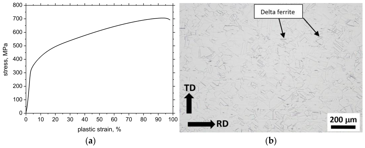
Figure 2.
3D images of surfaces after SP; (a) after rolling, (b) steel shots – 2 SP cycles, (c) steel shots – 8 SP cycles, (d) ceramic shots – 8 SP cycles.
Figure 2.
3D images of surfaces after SP; (a) after rolling, (b) steel shots – 2 SP cycles, (c) steel shots – 8 SP cycles, (d) ceramic shots – 8 SP cycles.
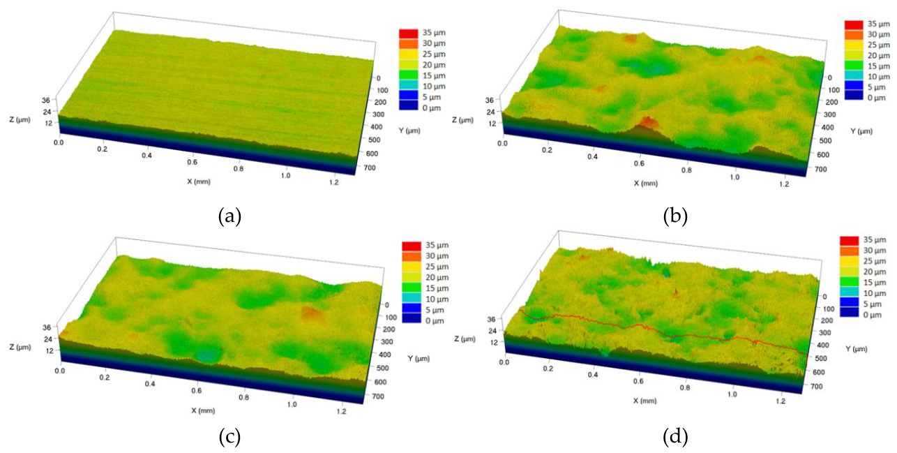
Figure 3.
PSa and PSz as a function of SP cycles and type of shots; (a) Psa, (b) PSz.
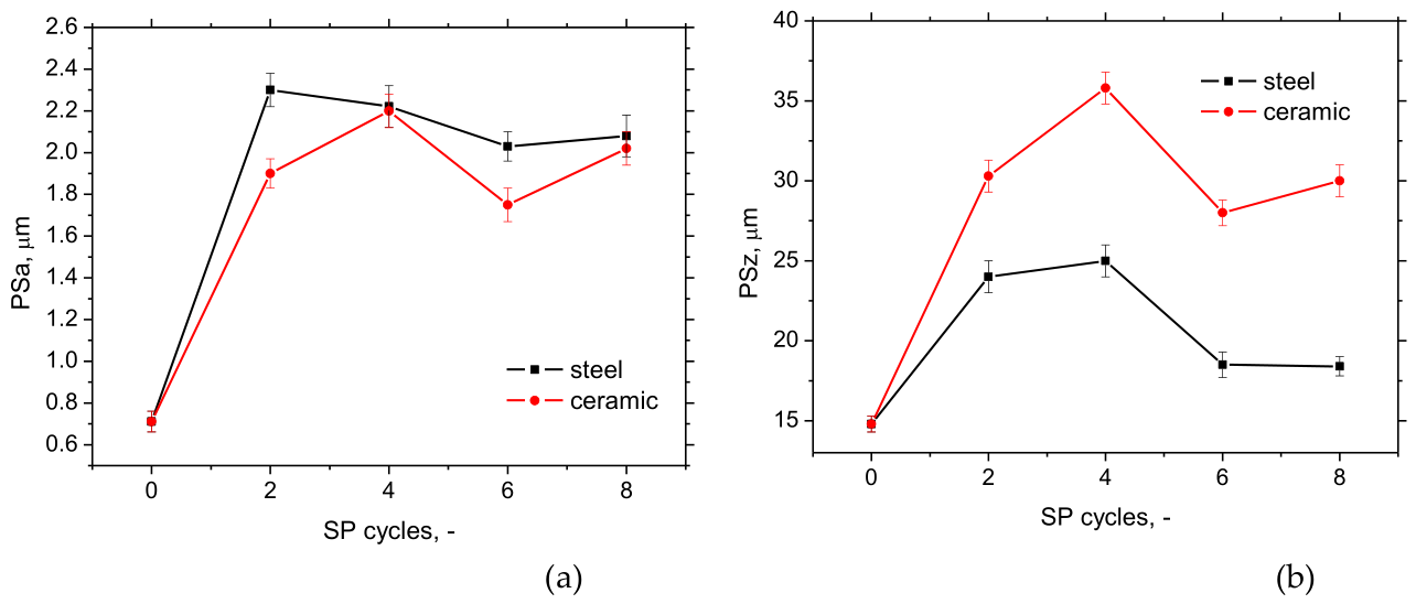
Figure 4.
Surface residual stresses as a function of SP cycles and type of shots; (a) in austenite, (b) in SIM.
Figure 4.
Surface residual stresses as a function of SP cycles and type of shots; (a) in austenite, (b) in SIM.
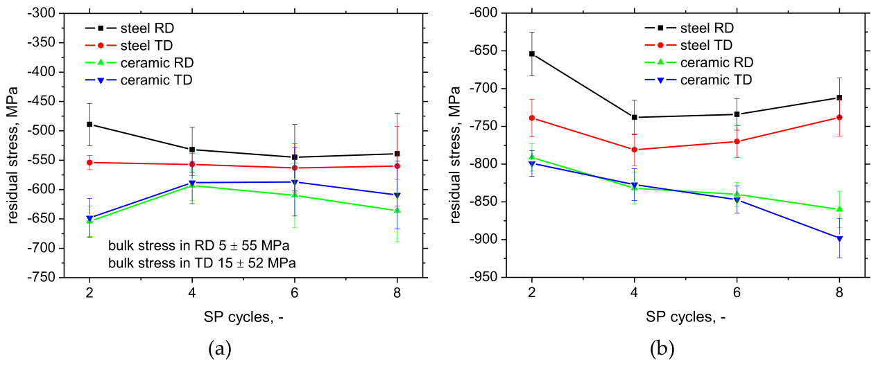
Figure 5.
Surface dislocation density and SIM fraction as a function of SP cycles and type of shots; (a) dislocation density in austenite, (b) SIM fraction.
Figure 5.
Surface dislocation density and SIM fraction as a function of SP cycles and type of shots; (a) dislocation density in austenite, (b) SIM fraction.
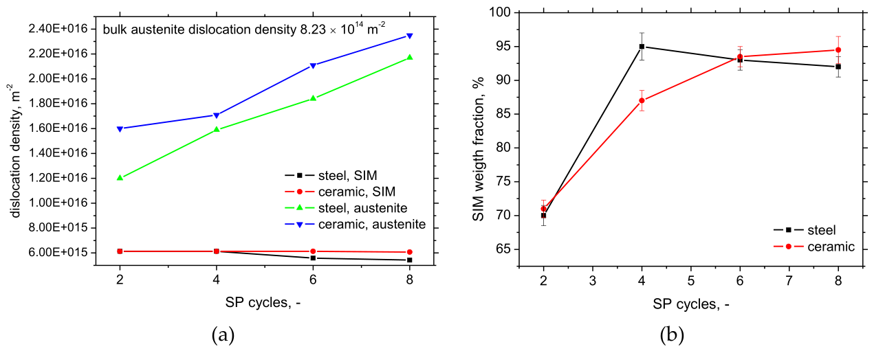
Figure 8.
EBSD images of surfaces after 6 SP cycles; (a) phase map for steel shots, (b) IPF map for steel shots, (c) KAM map for steel shots, (d) phase map for ceramic shots, (e) IPF map for ceramic shots, (f) KAM map for ceramic shots.
Figure 8.
EBSD images of surfaces after 6 SP cycles; (a) phase map for steel shots, (b) IPF map for steel shots, (c) KAM map for steel shots, (d) phase map for ceramic shots, (e) IPF map for ceramic shots, (f) KAM map for ceramic shots.
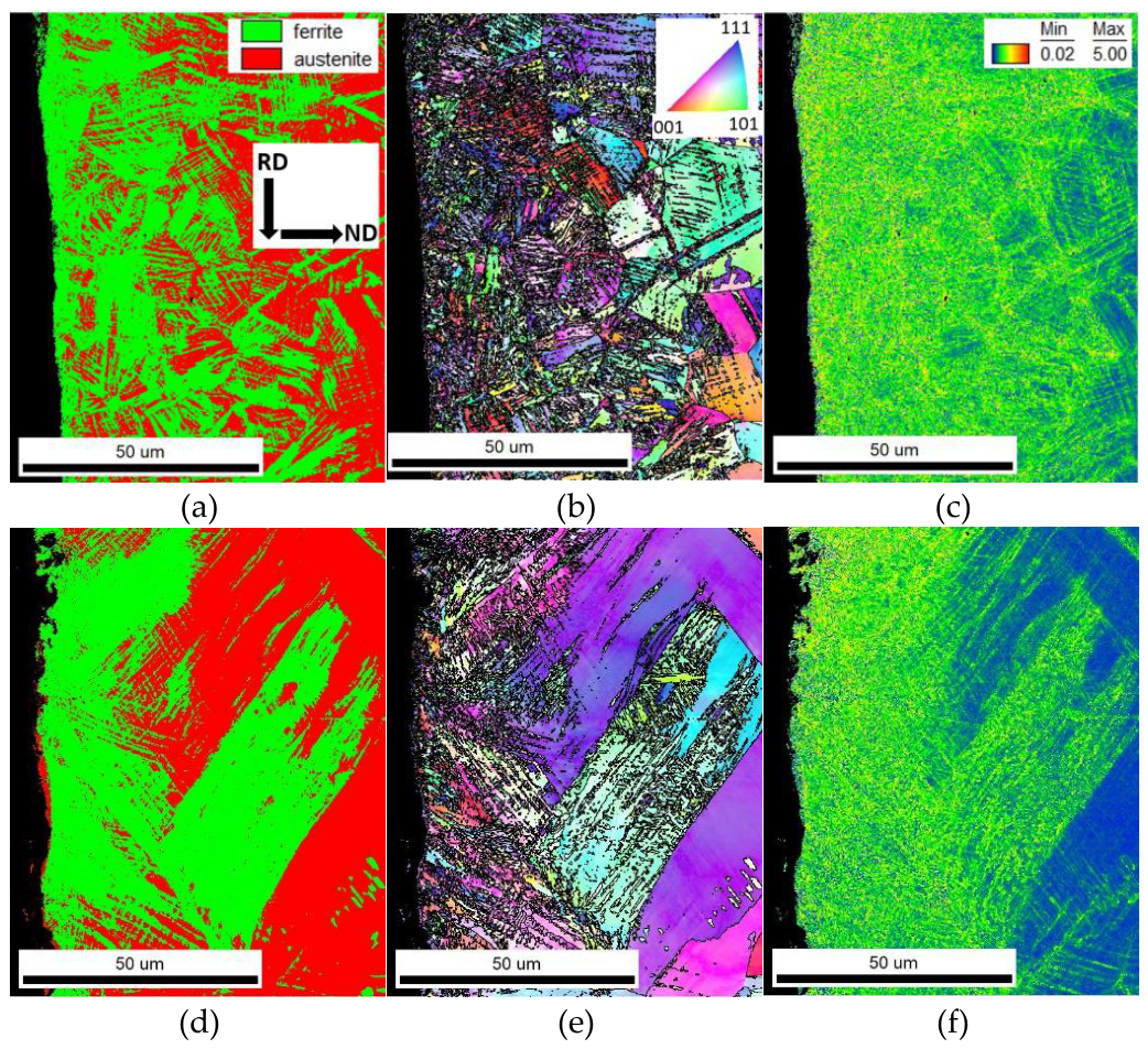
Figure 9.
Mössbauer CEMS spectra of surfaces after 8 SP cycles.
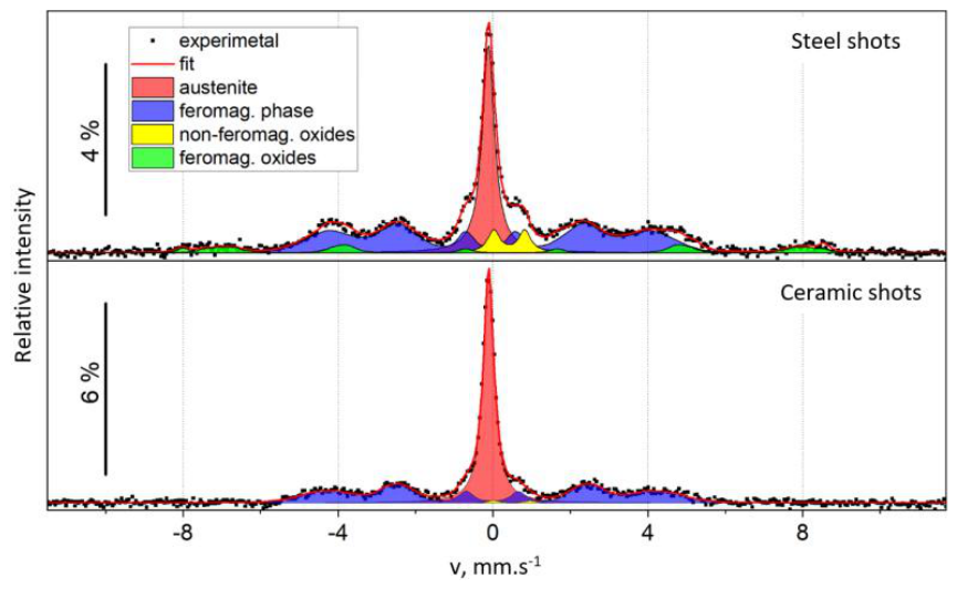
Figure 10.
MBN filtered signals; (a) 2 SP cycles, RD – steel shots, (b) 8 SP cycles, RD – steel shots, (c) 8 SP cycles, TD – steel shots, (d) 8 SP cycles, RD – ceramic shots.
Figure 10.
MBN filtered signals; (a) 2 SP cycles, RD – steel shots, (b) 8 SP cycles, RD – steel shots, (c) 8 SP cycles, TD – steel shots, (d) 8 SP cycles, RD – ceramic shots.
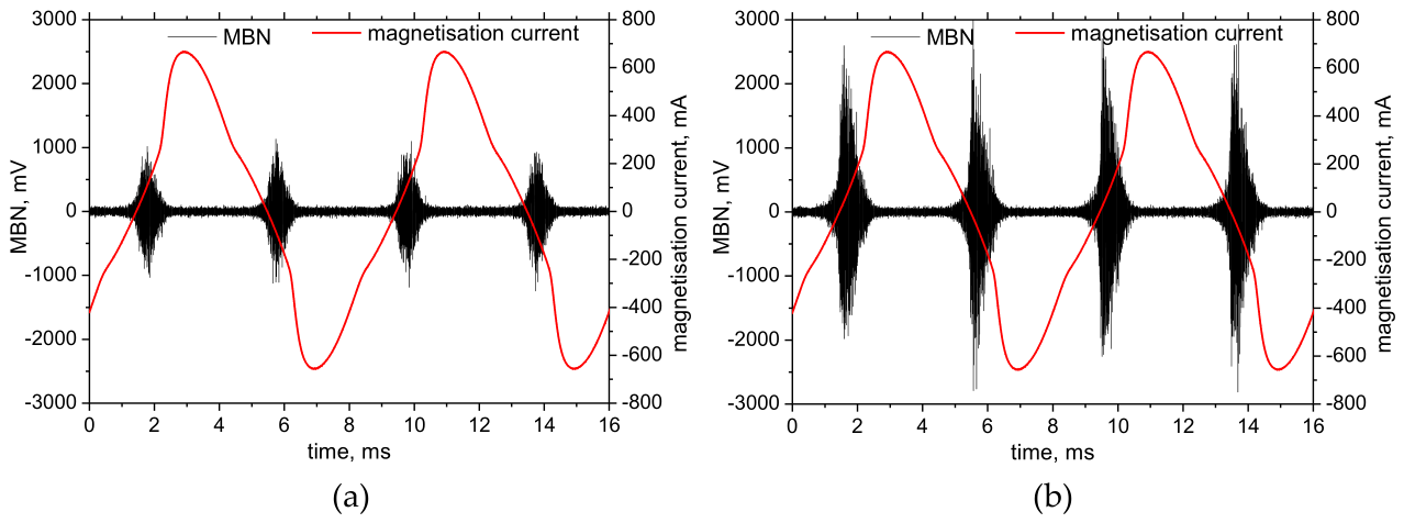
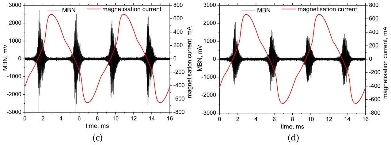
Figure 11.
MBN and PP as a function of SP cycles and type of shots; (a) MBN, (b) PP.
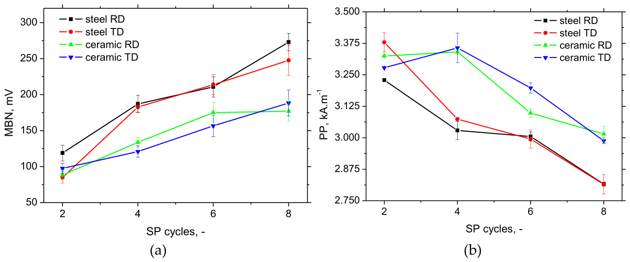
Figure 12.
Distribution of MBN pulse strength; (a) steel shots in RD, (b) 8 SP cycles in RD.
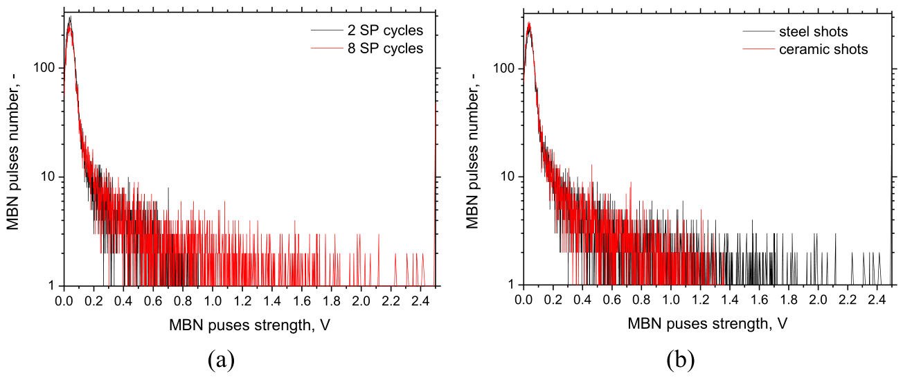
Figure 13.
Brief illustration of the shot mass and velocity on the energy consumed during impact.
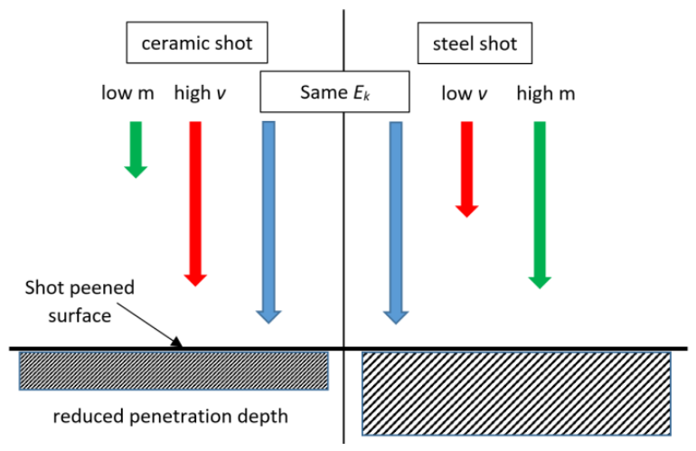
Figure 14.
Almen versus MBN; (a) RD, (b) TD.
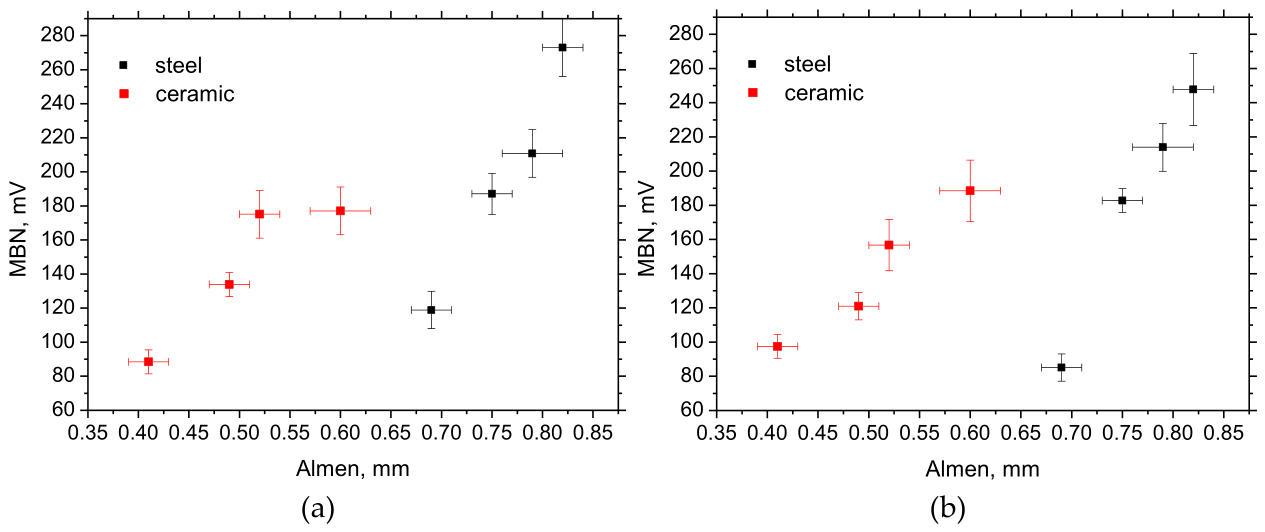

Table 1.
Chemical composition of AISI 304.
| C | Mn | Si | Cr | N | Ni | W | Mo | Ti | Co | Cu | Nb | V |
| 0,013 | 1,151 | 0,392 | 18,48 | 0,1 | 9,142 | 0,025 | 0,321 | 0,006 | 0,104 | 0,313 | 0,014 | 0,061 |
Table 2.
SP details.
| Shot size | 0.43 mm |
| Shots type | steel and ceramic |
| Gun | Guyson |
| Distance from the gun to the surface | 70 mm |
| The angle between the gun and the surface | 98° |
| The linear speed of the sample motion | 10 mm.s−1 |
| Air pressure | 5 bars |
Table 3.
Almen intensity (in mm) as a function of SP cycle number as well as shot type.
| Number of cycles | 2 | 4 | 6 | 8 |
| Steel shots | 0.69 ± 0.02 | 0.75 ± 0.02 | 0.79 ± 0.03 | 0.82 ± 0.02 |
| Ceramic shots | 0.41 ± 0.02 | 0.49 ± 0.02 | 0.52 ± 0.02 | 0.60 ± 0.03 |
Table 4.
Relative CEMS intensities for the different shots.
| Austenite | SIM | Non-magnetic oxides | Magnetic oxides haematite | Magnetic oxides magnetite | |
| Ceramic shots | 54.2 | 44.6 | 1.2 | - | - |
| Steel shots | 32.4 | 47.7 | 6.9 | 3.3 | 9.7 |
Table 5.
Quantities for the calculation of Ek.
| shot density, kg.m−3 | 7850 for steel shots and 2661 for ceramic shots |
| average shot diameter, mm | 0.43 |
| shot mass m, g | 0.33 × 10⁻³ for steel shots and 0.11 × 10⁻³ for steel shots and |
| air pressure p, bar | 5 |
| acceleration distance d, mm | 52 |
| shot velocity v, m.s−1 | 455 for steel shots and 781 for ceramic shots |
| kinetic energy Ek, J | 33.75 for steel as well as ceramic shots |
Disclaimer/Publisher’s Note: The statements, opinions and data contained in all publications are solely those of the individual author(s) and contributor(s) and not of MDPI and/or the editor(s). MDPI and/or the editor(s) disclaim responsibility for any injury to people or property resulting from any ideas, methods, instructions or products referred to in the content. |
© 2026 by the authors. Licensee MDPI, Basel, Switzerland. This article is an open access article distributed under the terms and conditions of the Creative Commons Attribution (CC BY) license (http://creativecommons.org/licenses/by/4.0/).
Copyright: This open access article is published under a Creative Commons CC BY 4.0 license, which permit the free download, distribution, and reuse, provided that the author and preprint are cited in any reuse.