

Submitted:
16 September 2026
Posted:
16 September 2026
You are already at the latest version
Abstract
Voxel-based video games offer an interactive platform for simulating complex digital logic architectures. This paper presents the design and functional evaluation of a redstone arithmetic calculator capable of performing addition and subtraction on two three-digit numbers within Minecraft Java Edition Version 1.21.1. Hosted on a Spigot/Paper server fixed at 20 game ticks per second, the system establishes a deterministic operational clock to eliminate signal disconnection and timing race conditions across circuit arrays. Decimal inputs from a ten-key button panel are encoded into 4-bit Binary-Coded Decimal (BCD) representations via a diode matrix and latched using D Flip-Flop registers. A weighted combinational translator aggregates positional values into a unified binary format optimized for computation. The central Arithmetic Logic Unit executes bitwise addition and Two’s Complement subtraction governed by an RS Flip-Flop control line, with data routed across a synchronized parallel bus featuring passive delay calibration. The binary output is converted back into decimal format through a Double Dabble shift-add-three architecture to drive a seven-segment redstone Lamp display. Experimental results confirm deterministic signal execution and accurate visual output across all valid operations, demonstrating that spatial gaming environments serve as viable platforms for visualizing physical hardware design and computer engineering principles.
Keywords:
Minecraft Redstone
; Arithmetic Logic Unit (ALU)
; Binary-Coded Decimal (BCD)
; two’s complement
; digital circuit simulation
; 7-Segment Display
1. Introduction
Voxel-based sandbox games such as Minecraft provide an unexpectedly capable environment for constructing digital logic, and a small but growing body of work shows that a functional Arithmetic Logic Unit (ALU) can be designed and built entirely from the game’s redstone system. The most directly relevant study modeled a Minecraft ALU supporting the logic operations OR, NOR, AND, NAND, XOR, and XNOR together with arithmetic addition and subtraction, and reported that all standard operations functioned correctly [1]. This narrow but concrete result sits within a broader engineering literature in which ALUs are organized as combinational logic blocks with separate logic and arithmetic units, opcode-based control, multiplexers, and cascaded one-bit slices that form wider datapaths [2,3].
The Minecraft-specific literature shifts the emphasis from transistor efficiency toward buildability, routing, verification, and educational value. Automated redstone place-and-route work identifies vertical signal transmission as a concrete design obstacle [4], and later routing software reports large speedups with the explicit goal of scaling to entire processors inside Minecraft [5]. A digital-twin Minecraft environment further shows that redstone asynchrony and latency can be mitigated through controlled signal injection and software clock synchronization, enabling deterministic validation of both combinational and sequential circuits [6]. Across the adjacent education literature, simulation and game-based environments consistently improve motivation, engagement, and understanding of abstract computer-architecture and digital-logic concepts, although they do not fully replace physical laboratories [7].
Motivated by this potential, the present work designs and builds a redstone calculator that performs addition and subtraction on two three-digit numbers within Minecraft Java Edition Version 1.21.1. The implementation draws on concepts from tutorials by the YouTube channel MattBatWings [8], adapted to the objectives and requirements of this project, and is detailed in the sections that follow.
2. Related Work
Direct evidence that an ALU can be realized in Minecraft comes primarily from a single implementation study, which built logic and add/subtract functionality from redstone components and verified correct operation [1]. Complementary tooling research treats redstone construction as a computer-aided design problem: an automatic place-and-route tool demonstrated netlist-to-redstone layout generation while highlighting vertical signal transmission as a major obstacle [4], and subsequent work reported incremental routing improvements aimed at processor-scale builds [5]. More recent efforts apply multimodal models to configure redstone circuits automatically [9], and a digital-twin framework couples automated circuit verification with real-time simulation to make redstone logic deterministically testable [6].
The wider hardware literature establishes the architectural patterns that a redstone ALU inherits. ALUs are consistently organized around a functional split between logic and arithmetic units with opcode-driven operation selection [2], and wider datapaths are built by cascading validated one-bit or four-bit slices [3,10]. Alternative implementations—from reversible logic gates [3] to recursive multi-function circuits [11]—show that the same functional requirements can be met across very different technologies, and that regular or recursive layouts are advantageous for automated synthesis and routing [11]. Minecraft does not change what an ALU must compute, but it makes operand width, routing, and timing first-order design constraints rather than implementation details [4].
Timing is the redstone-specific concern most emphasized in the literature. The digital-twin study states directly that redstone asynchrony and latency require controlled signal injection and software clock synchronization to achieve deterministic validation [6], which aligns with conventional findings that ALU delay depends strongly on circuit organization and carry-propagation structure [3,10].
Finally, a substantial education literature motivates building ALUs in game environments. Minecraft-style and sandbox educational games provide immediate feedback, spatial interaction, and puzzle-based circuit repair that improve motivation and learning in digital-logic contexts [12], and three-dimensional virtual laboratories have been used specifically to teach ALU design [13]. Broader syntheses report a moderate positive effect of virtual laboratories on engineering-education outcomes, with especially large gains in motivation and engagement, while noting that such environments do not fully replace hands-on laboratories [7]. Complementary hands-on approaches reinforce this conclusion: project-based electronics built around physical prototyping boards such as Arduino have proven effective in supplementary computer-engineering education [14], and structured courses combining three-dimensional modeling with virtual reality show how immersive tools can be organized into coherent learning outcomes [15].
A recurring theme across these studies is that the three capabilities central to this work—BCD encoding, Two’s Complement subtraction, and seven-segment visualization—can be integrated into a single deterministic design by combining validated redstone logic architectures with a display-decoder stage [1,16]. The redstone ALU already demonstrated in Minecraft executes the full logic set (OR, NOR, AND, NAND, XOR, XNOR) alongside ADD and SUB under opcode-style control, confirming redstone’s viability for deterministic digital computation [1]. Complementary FPGA work shows the same integration at the hardware level: dedicated logic manages carry and overflow for reliable Two’s Complement subtraction, and a display-decoder module maps the binary result onto a seven-segment panel for intuitive, real-time readout of both results and status flags [16].
Figure 1 summarizes this integrated architecture, in which operands are routed by an opcode selector to either the logic gates or the adder/subtractor, status flags capture carry and overflow, and the result bus feeds a BCD/display decoder that drives the seven-segment output. The remainder of this paper details how each of these stages is realized entirely in redstone.
3. Materials and Methods
3.1. Server Environment and Timing Infrastructure
The digital logic circuits were built inside Minecraft [17] Java Edition Version 1.21.1. The project was hosted on a dedicated Spigot/Paper server [18] to help the team work together and keep the circuits running smoothly. The server provided a shared world for everyone to build in and kept the clock running at a steady speed.
Redstone [19] circuits are based on predictable timing in Minecraft [17], where signals update every two game ticks, which equals one redstone tick [20]. The server was set to 20 game ticks per second (10 redstone ticks [20] per second). It acts as a reliable clock for all circuits, and with this speed kept steady, it prevents signals from breaking, skipping ticks, or falling out of order. Additionally, we turned off the in-game settings for daylight cycles, weather, and monster spawning (doDaylightCycle, doWeatherCycle, and doMobSpawning are set to false). This stopped background lag and lighting changes from causing issues. The full world file and server settings are saved in the project repository so anyone can recreate the exact setup.
3.2. Keypad Input Encoding (Decimal to Binary-Coded Decimal)
The user interface starts with a panel of 10 stone buttons for the numbers zero through nine. Since people use decimal numbers while the circuit uses binary logic, the system needs to convert the input right away. When a player presses a button, it sends a short two-redstone-tick [20] signal into an encoder. This encoder turns each decimal button press into a 4-bit Binary-Coded Decimal (BCD) signal (0000 to 1001). To remember these numbers as the user enters multiple digits, the BCD values are saved in temporary memory using D Flip-Flop registers, which create a steady bridge between the keypad and the rest of the redstone [19] circuits. Figure 2 shows the matrix layout of the keypad decimal-to-BCD encoder built using redstone. It maps raw decimal button inputs into 4-bit BCD signals and routes them through a structured physical grid into output bit lines.
3.3. Data Transformation (BCD to Pure Binary Conversion)
Even though Binary-Coded Decimal (BCD) is great for holding single numbers, doing math directly with BCD requires complicated steps. To make calculation simple, the system sends the 4-bit BCD numbers through a translator circuit that converts the multi-digit numbers into one single binary number. This process combines the place values such as hundreds, tens, and ones into a single binary format that the Arithmetic Logic Unit (ALU) can easily process. The conversion uses adder circuits to run this with the formula:
Binary Output = (Hundreds × 100) + (Tens × 10) + Units
This step turns the multi-digit BCD inputs into a binary word that is ready for the core logic parts to do direct math on.
3.4. Control Unit and Mode Selection Logic
Operational control is managed by dedicated switches connected to an RS Flip-Flop circuit, which acts as the system’s memory for picking the math mode. When the user presses an addition or subtraction button, this control unit switches on and holds an internal setting bit. The memory circuit output controls the main command line, which tells the main adder module how to behave: an OFF signal tells the Arithmetic Logic Unit (ALU) to perform standard binary addition, while an ON signal turns on the reversing step needed to do Two’s Complement subtraction.
3.5. Primary Arithmetic Logic Unit (Binary Addition)
The main calculation engine of the calculator is a multi-bit Ripple Carry Adder built from basic redstone [19] logic gates, including XOR, AND, and OR gates, along with redstone [19] repeaters. It works like adding numbers by hand in columns: the circuit uses XOR gates to calculate the sum and combines AND and OR gates to pass along remaining values. During a calculation, each bit position adds its two input bits together and sends any extra signal to the next position to the left, allowing smooth multi-bit math across the entire array.
Figure 3 shows the physical configuration of the 8-bit ripple-carry binary full-adder ALU built using redstone. It processes parallel binary inputs across chained full-adder modules and propagates carry bits sequentially to execute arithmetic operations.
3.6. Subtraction Mechanism (Two’s Complement Logic)
The method uses a computer-science approach known as Two’s Complement to do subtraction without creating a separate subtractor circuit. When subtraction mode is activated, the second number goes to a series of inverter gates that flip all of its binary bits, changing every ON signal to OFF and every OFF signal to ON. To finish the transformation, an additional signal of 1 is injected at the same time into the first position of the primary adder circuit. This lets us save physical space and reuse the same ALU hardware by tricking the machine into calculating subtraction by passing the flipped integer through the usual adder.
Figure A1 and Figure A2 in Appendix A show the top view and side profile of the Two’s Complement inverter array. The module inverts binary signals and routes them vertically through structured redstone logic to perform subtraction operations.
Figure A3 in Appendix A shows the output evaluation and rendering mechanism displaying a negative calculation result on the redstone lamp screen. It verifies signal integrity by accurately calculating 151 − 167 = −16 and rendering the dynamic negative sign alongside the multi-digit BCD output.
3.7. System Bus and Signal Routing
Moving information between different modules is handled by an organized, shared communication line called the System Bus. The System Bus acts like a structured data highway that replaces tangled wires and keeps signals moving smoothly. To keep redstone [19] signals from dying out over long distances, repeaters and signal isolators are placed every 15 blocks along the lines. Additionally, signal timing is kept synchronized across all lines by adding extra repeater delays along shorter paths. This careful timing calibration guarantees that all the binary data arrive safely at the target modules at exactly the right time within the same redstone tick [20].
3.8. Output Conversion (Binary to BCD Transformation)
After doing the math, the raw binary output from the ALU needs to be changed back into standard numbers that humans can easily read. The system sends this binary result through a converter circuit that uses a special method called the Double Dabble algorithm [21]. This circuit splits the binary number into separate 4-bit BCD chunks for each decimal place value, such as the hundreds, tens, and ones. These BCD chunks are then sent straight to a decoder circuit that translates each 4-bit code into seven control wires. These wires turn on specific redstone [19] Lamps set up like a display to show the final number on screen.
Figure 4 shows the physical layout of the binary-to-BCD converter subsystem array implemented in Minecraft redstone. It takes raw binary outputs from the ALU and uses cascading shift-add-3 logic modules to convert binary values into BCD digits for the display screen.
3.9. Visual Display Decoding and Rendering (BCD to 7-Segment Output)
The final stage turns the processed BCD numbers into a visual display. Each 4-bit BCD number goes into a decoder circuit that maps the binary code to the physical layout of a standard 7-segment panel. The decoder turns on specific redstone [19] Lamp arrays, lighting up the exact segments needed to show readable numbers from zero through nine so the player can easily see the final calculation result.
Figure A4 and Figure A5 in Appendix A depict the structural layout and routing logic used to drive the 7-segment display module. Redstone bus connections process decoded input signals from a top-to-down perspective (b) and route them through tiered repeater buffers (a) to power individual screen segments without signal decay.
Figure A6 and Figure A7 in Appendix A showcase the front-facing visual interface built from redstone lamp arrays. Individual 7-segment display units (a) are tiled together to form a multi-digit output matrix (b) capable of rendering numerical results and mathematical operators.
4. Results
4.1. Overall World Build and Module Map
The complete physical implementation integrates each individual logic circuit within the 3D voxel space of Minecraft Java Edition Version 1.21.1. To maintain reliable signal timing across all physical modules, the system operates on a dedicated Spigot/Paper server [18] locked at 20 game ticks per second, establishing a deterministic operational clock rate of 10 redstone ticks [20] per second. Background engine processes, including weather, daylight cycles, and mob spawning, were disabled to eliminate lag spikes and visual lighting updates that could disrupt signal processing.
The physical layout arranges hardware modules sequentially along a unified system bus. Calculation begins at a 10-key decimal keypad where button presses trigger a diode matrix encoder to generate 4-bit Binary-Coded Decimal (BCD) values, which are latched in temporary memory using D Flip-Flop registers. These positional BCD signals are routed into a weighted combinational translator that converts multi-digit inputs into an 8-bit binary word. The translated binary data flows directly to the Arithmetic Logic Unit (ALU), which features an 8-bit Ripple Carry Full Adder connected to a Two’s Complement inverter array and an RS Flip-Flop control unit for mode selection. After processing, the binary result is sent through a Double Dabble algorithm [21] circuit to convert the value back into separate BCD digits. It then passes from BCD to 7-segment decoders and drives the final redstone Lamp display panel. Signal attenuation and timing inconsistencies across long transmission lines are mitigated by placing repeaters every 15 blocks alongside passive delay calibration, ensuring all binary bits arrive at their destination simultaneously within the same redstone tick [20].
4.2. In-Game Simulation
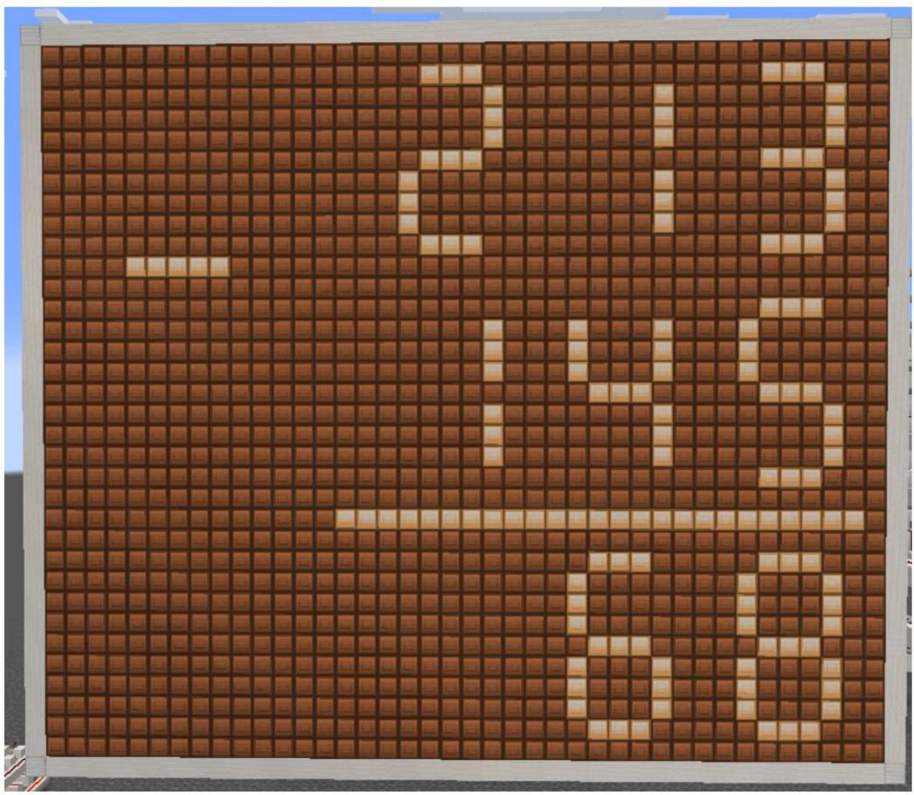
After building the components we need, we tested and verified the accuracy and signal integrity of the integrated calculator across both addition and subtraction modes. Both two-digit and full three-digit arithmetic equations were calculated and displayed directly on the redstone lamp screen. Figure A8, Figure A9, Figure A10 and Figure A11 in Appendix A demonstrate the testing of addition and subtraction for two and three digits.
5. Discussion
The implementation of the redstone [19] calculator proves that 3D block games like Minecraft [17] can be used to test and learn how real computers work. It shows that basic computer parts like logic gates, memory, and display converters can be built inside a 3D game world to do accurate math. Traditional circuit design software (like Logisim or SPICE) focuses only on fast, idealized calculations on a flat screen, but Minecraft [17] makes you deal with physical space. In Minecraft [17], redstone [19] signals lose power over long distances and take extra time to travel through repeater delay blocks. This forces you to solve real-world hardware problems, such as wire placement and signal timing, similar to how engineers design real computer chips.
Successfully building subtraction and number-conversion circuits proves that redstone [19] can handle standard computer tasks. However, building a calculator inside Minecraft [17] comes with clear limitations caused by the game itself. Because the game server runs at a fixed speed of 10 redstone ticks [20] per second, these calculations are much slower than what real computer chips can do. On top of that, handling larger numbers requires bigger physical structures in the game world, which forces signals to travel longer distances and slows the system down. Future projects could improve on this design by using faster calculation techniques to reduce signal delays or by processing tasks in overlapping steps to increase speed.
6. Conclusions
In this project, we successfully built and tested a working redstone [19] calculator inside a controlled Minecraft [17] server. The system brings together all key computer components into one build, including a number keypad, input encoders, a main math engine for addition and subtraction, organized signal wiring, and a visual lamp screen. By locking the game timing and turning off background lag, the calculator reliably performs multi-digit math without signal drops or timing errors. Ultimately, this work demonstrates that Minecraft [17] redstone is an excellent hands-on tool for teaching computer engineering, turning abstract theoretical ideas into clear 3D physical models.
Appendix A
This appendix collects the supplementary hardware views and functional-test figures referenced in the main text.
Figure A1.
Top view of the Two’s Complement inverter array.
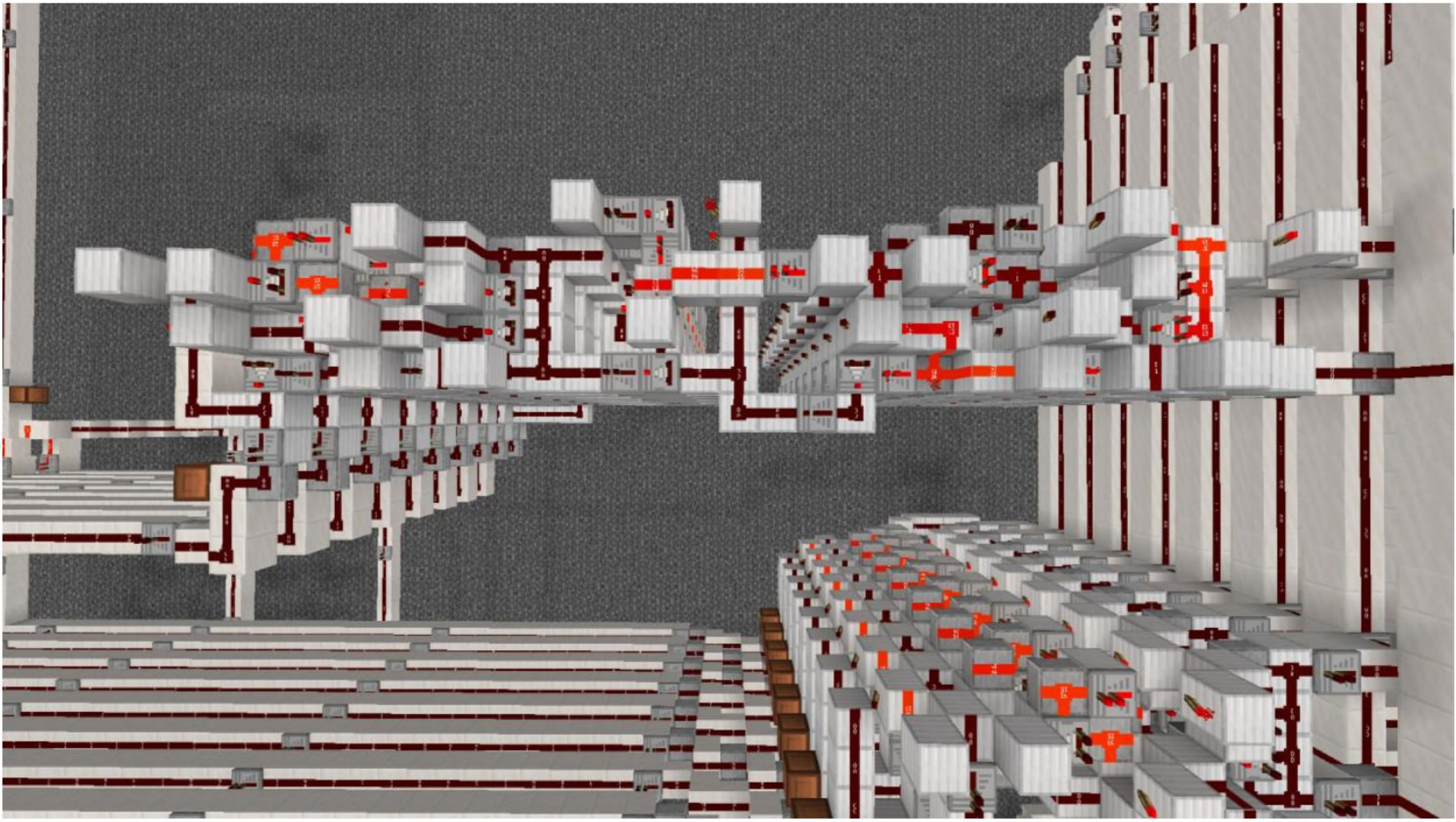
Figure A2.
Side profile displaying vertical redstone [19] signal routing for subtraction.
Figure A2.
Side profile displaying vertical redstone [19] signal routing for subtraction.
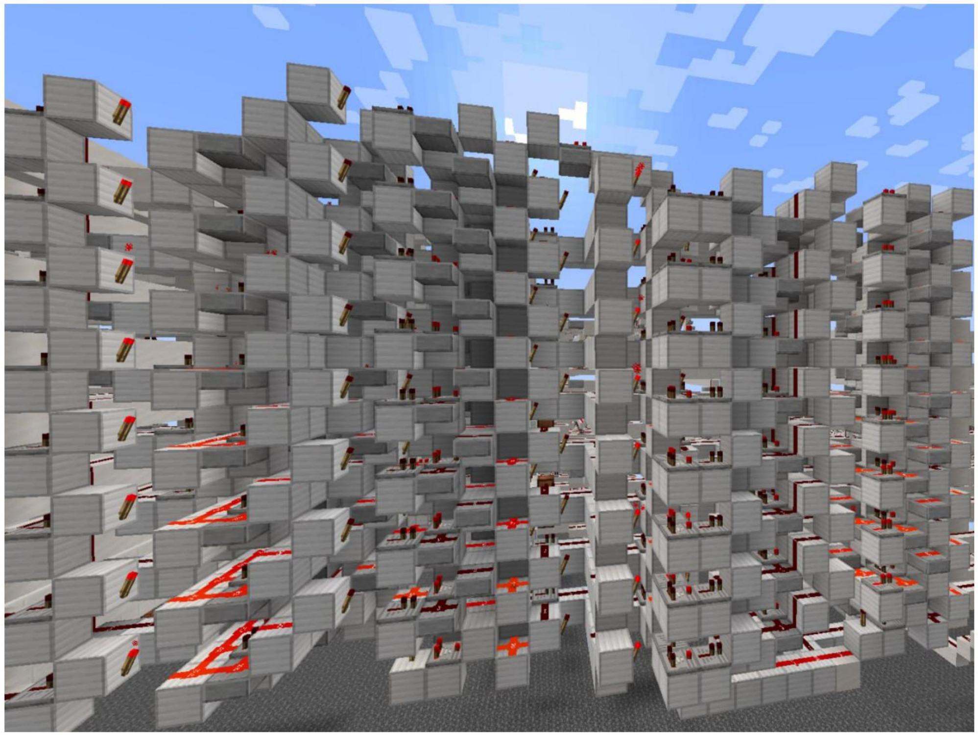
Figure A3.
Output evaluation and rendering mechanism for negative result values.
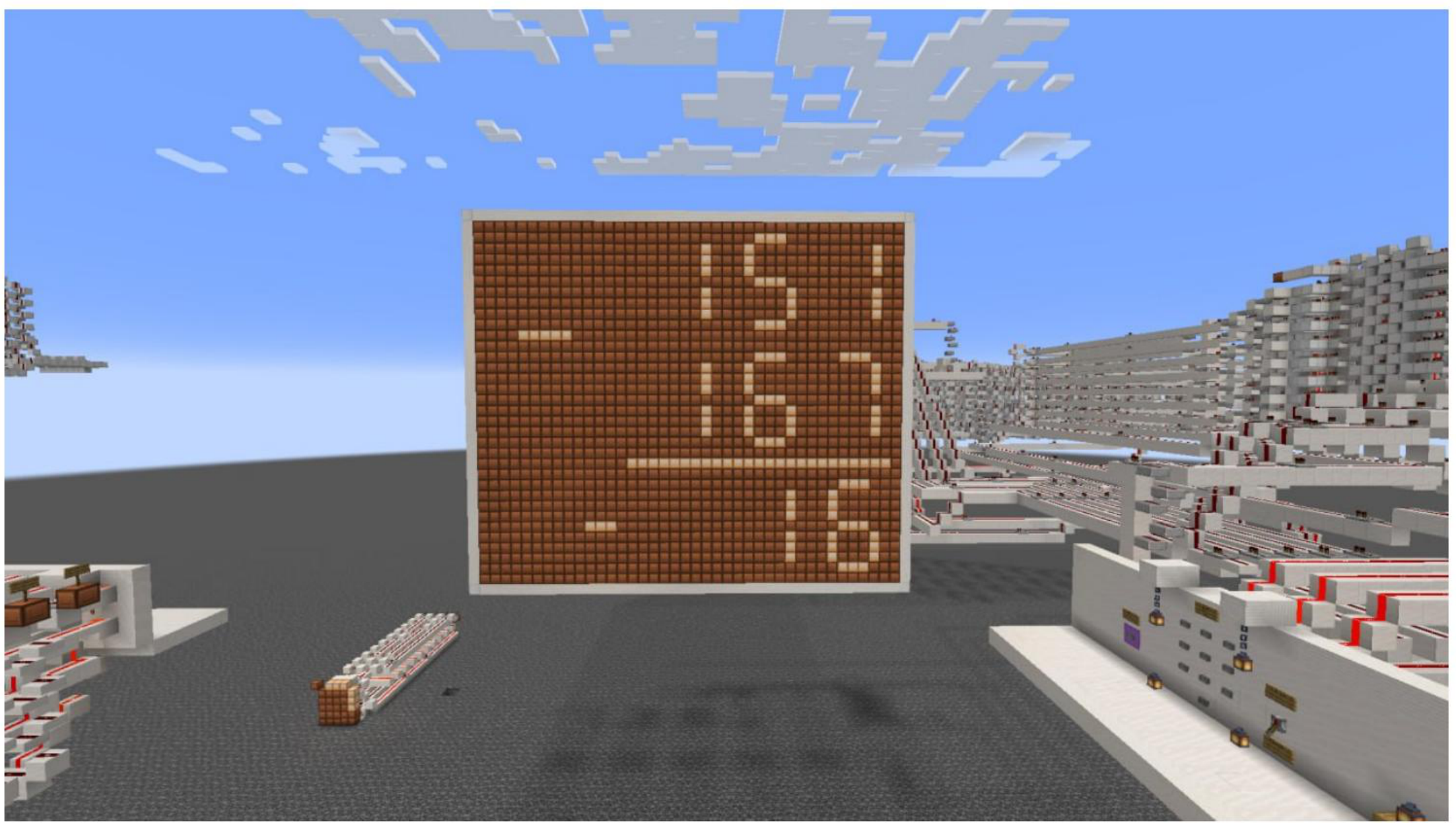
Figure A4.
Side profile of segment line driving circuitry and repeater buffers.
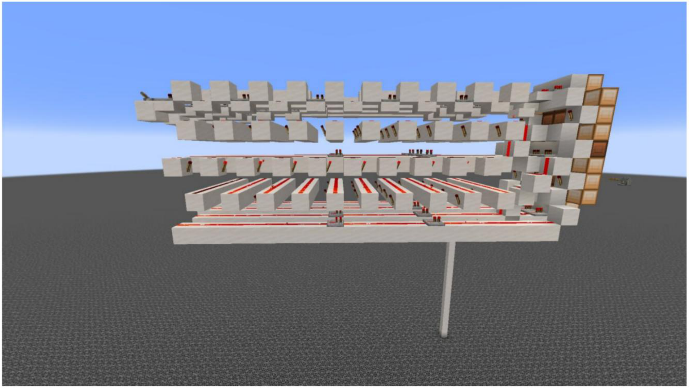
Figure A5.
Top-down view of display line decoding and bus connections.
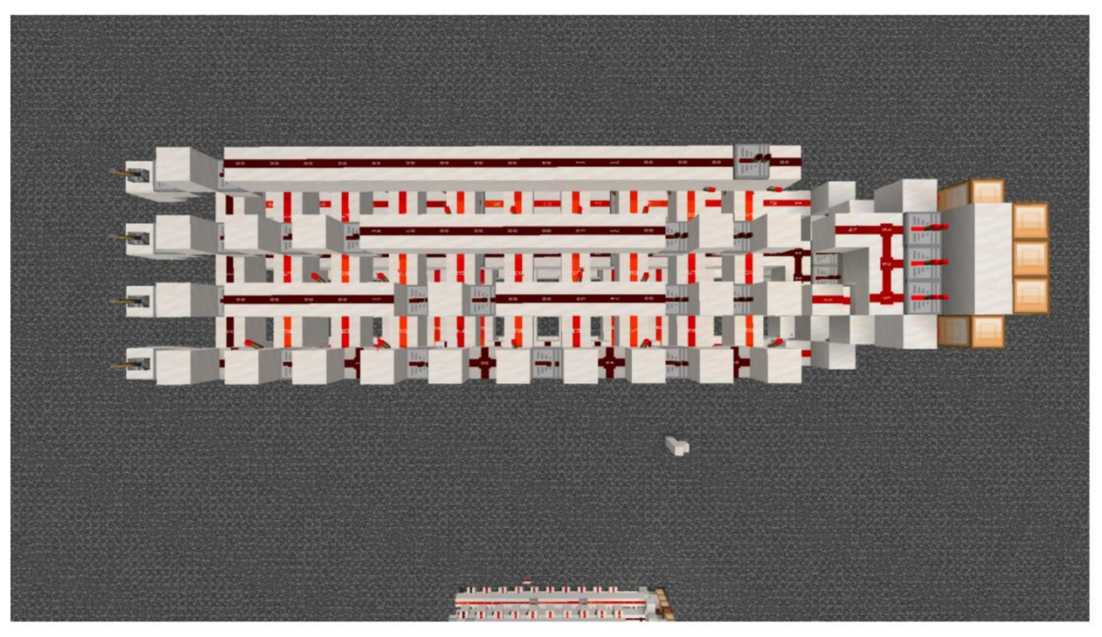
Figure A6.
Front elevation of the 7-segment redstone lamp visual display panel.
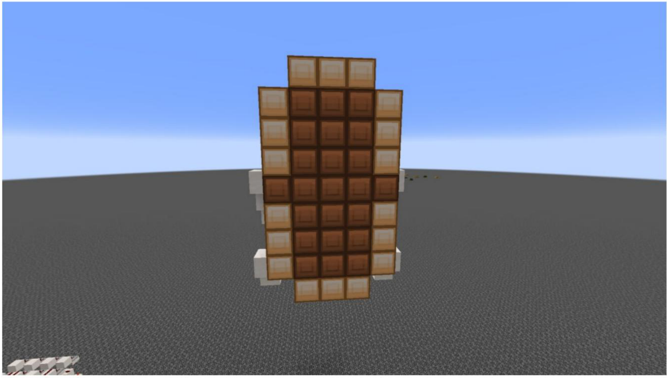
Figure A7.
Single-digit 7-segment lamp matrix unit layout.
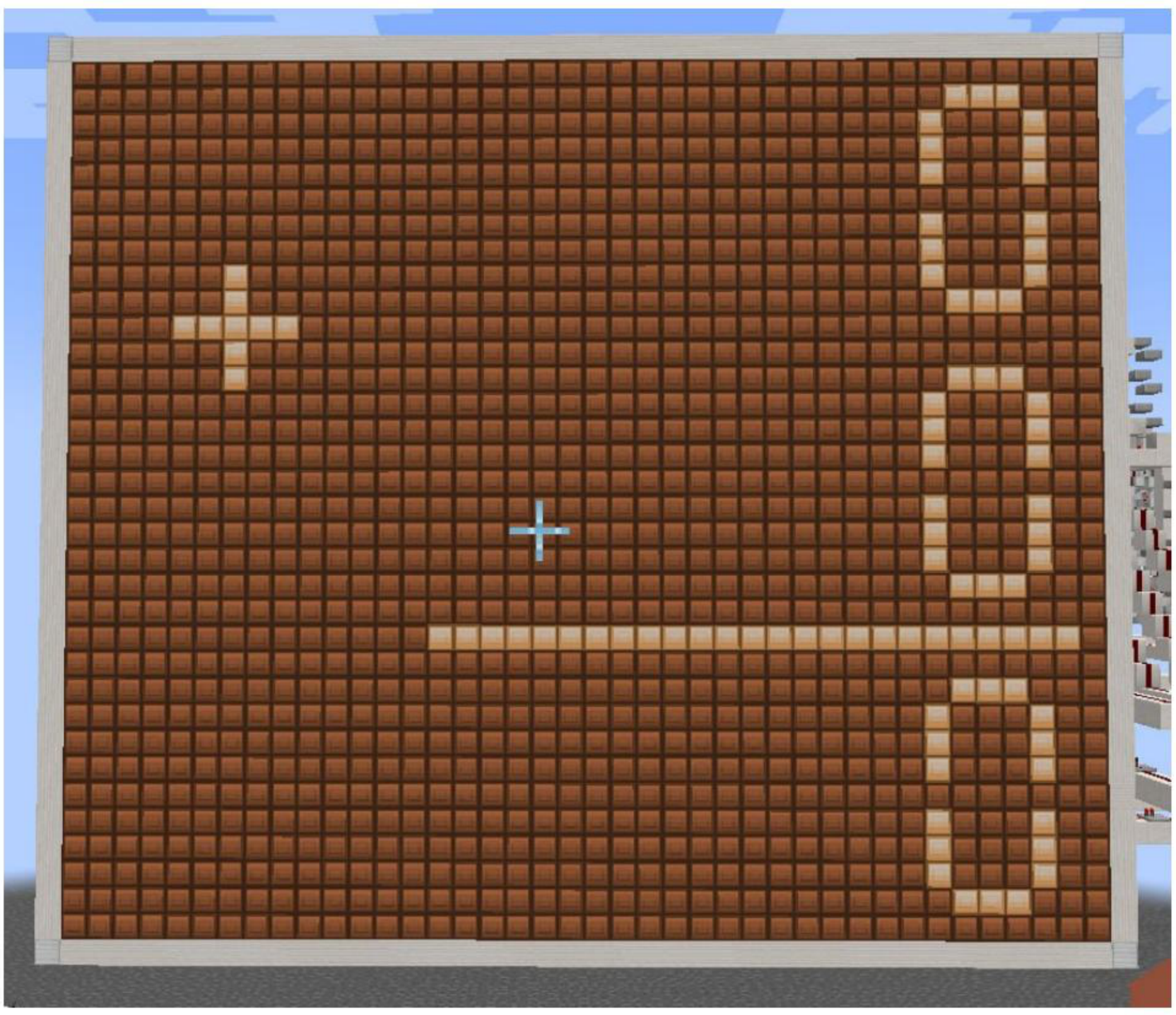
Figure A8.
Functional test execution of two-digit addition on the visual display.
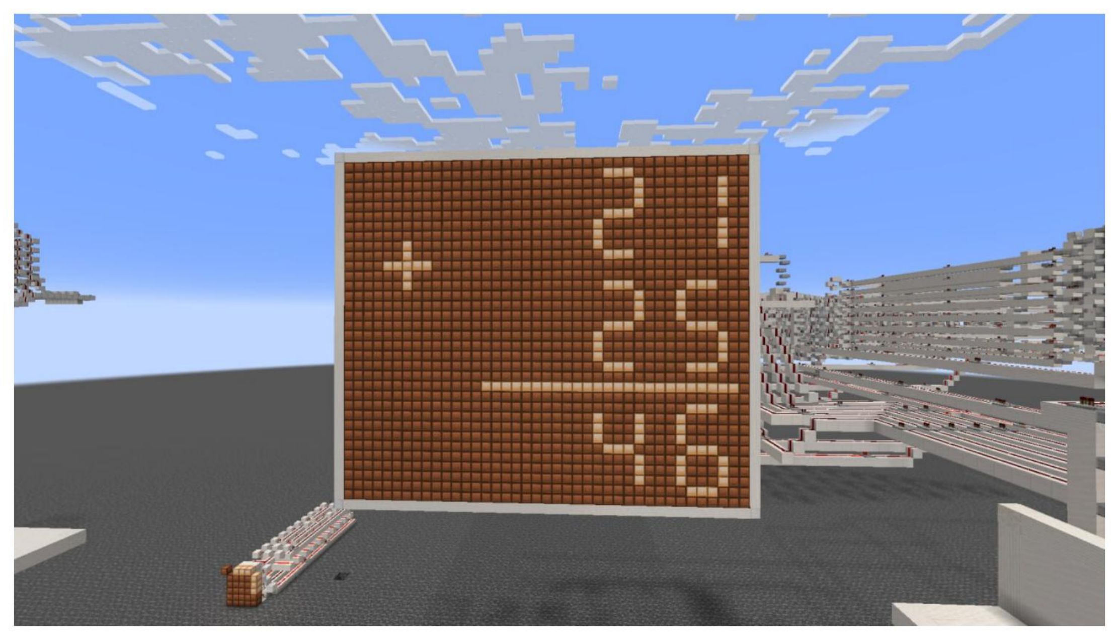
Figure A9.
Functional test execution of two-digit subtraction on the visual display.
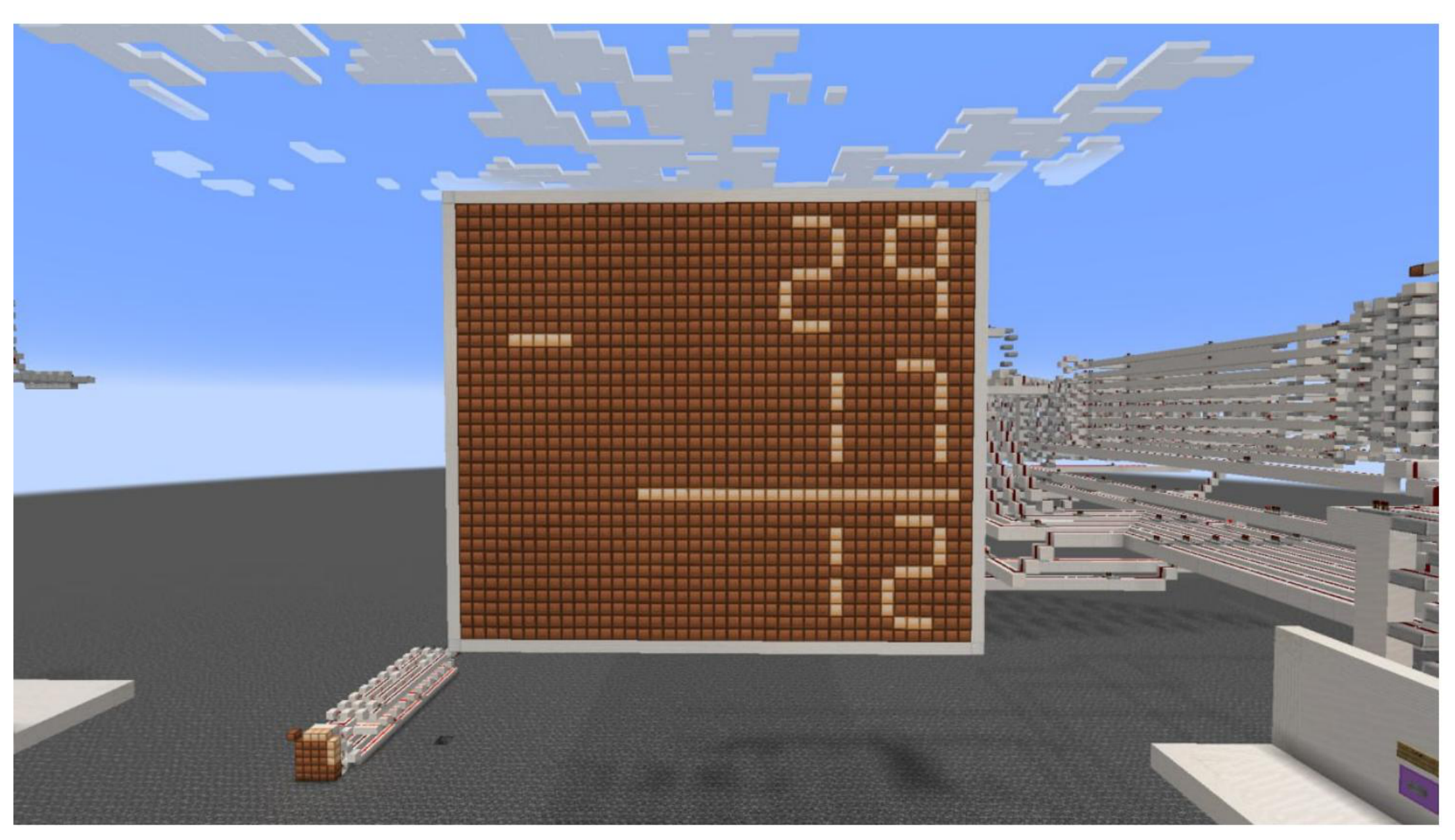
Figure A10.
Full-scale three-digit addition simulation output render.
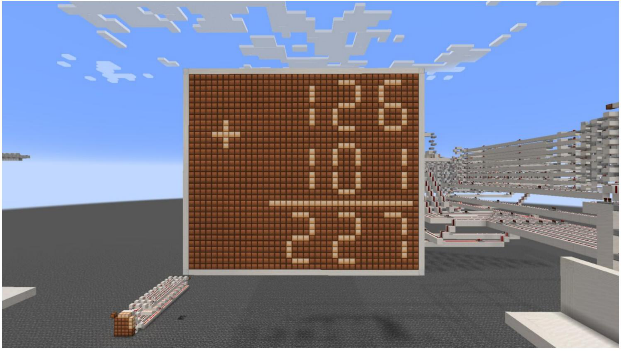
Figure A11.
Full-scale three-digit subtraction simulation output render.
References
- Diny, M. Z.; Nuha, H.; Rakhmatsyah, A. “Pemodelan ALU pada Mikroprosesor MIPS Menggunakan Redstone di Minecraft,” 2019.
- K. N. K.V., B. V.R., P. M., S. S.S., and D. A.N., ASIC Design and Implementation of 32-Bit Arithmetic and Logic Unit. EAI Endorsed Trans. Energy Web 2024, vol. 11. [CrossRef]
- Priyanka, V.; Arab, M. A.; Reddy, N. S.; Jeevana, G. Design of Arithmetic Logic Unit Using Reversible Logic Gates. 2024 2nd World Conf. on Communication & Computing (WCONF); 2024, pp. 1–6. [CrossRef]
- PERSHING: An Automatic Place-and-Route Tool for Minecraft Redstone Circuits. 2016.
- Nguyen, Q. M. Incremental Improvements on the Placement and Routing of Minecraft Redstone Circuits; 2018. [Google Scholar]
- Cruz García, D.; Correa, I.; García González, S.; Álvarez Sánchez, A.; González, G. V. Digital Twin for Designing Logic Gates in Minecraft Through Automated Circuit Verification and Real-Time Simulation; Electronics, 2026. [Google Scholar] [CrossRef]
- Li, J.; Liang, W. Effectiveness of Virtual Laboratory in Engineering Education: A Meta-Analysis. PLoS ONE 2024, vol. 19. [Google Scholar] [CrossRef] [PubMed]
- MattBatWings, “MattBatWings YouTube Channel,” YouTube. 2021. Available online: https://www.youtube.com/@mattbatwings.
- Kobayashi, K.; Sato, T. Automated Configuration of Redstone Circuits in Minecraft Using a Multimodal Model. 2025 SICE Festival with Annual Conf. (SICE FES); 2025, pp. 1040–1047. [CrossRef]
- Arunabala, C. Design of a 4-Bit Arithmetic and Logical Unit with Low Power and High Speed. Int. J. Innov. Technol. Explor. Eng. 2021. [Google Scholar] [CrossRef]
- Roy, S. Efficient Arithmetic and Logic Unit (ALU) Design Based on Recursive Multi-Function Circuits. 2024 58th Asilomar Conf. Signals Syst. Comput. 2024, 314–321. [Google Scholar] [CrossRef]
- Lee, H.-M.; Hou, H.-T. Design and Preliminary Evaluation of a Remote Digital Logic Educational Game Combined with Sandbox Game Mechanisms. SEACE Official Conf. Proc., 2025. [Google Scholar] [CrossRef]
- Rodríguez, N.; Mora, J.; Nieto, I.; Santamaría, J.; Chanto, E. Designing an Arithmetic Logic Unit (ALU) in Virtual Laboratory in 3D. 2022 Congreso de Tecnología, Aprendizaje y Enseñanza de la Electrónica (TAEE), 2022; pp. 1–4. [Google Scholar] [CrossRef]
- Isaev, R. R.; Gadiev, R. M.; Satyev, A. I.; Grigoriev, A. I.; Maksyutov, D. R. Using the Arduino prototyping board in project activities of supplementary education. In Vestnik of the M. Akmulla Bashkir State Pedagogical University; (in Russian). 2016; Volume no. 4-2, pp. 48–52. [Google Scholar]
- Isaev, R.; Migranov, R. Designing a 3D and Virtual Reality Course: Integrating Technology and Creativity for Immersive Learning. 2025. [Google Scholar] [CrossRef]
- Kumar. Design and Implementation of a 3-bit ALU with Integrated 7-Segment Display on FPGA. Int. J. Sci. Res. Eng. Manag. 2024. [Google Scholar] [CrossRef]
- Mojang Studios, “Minecraft Official Wiki,” Minecraft Wiki, 2024. Available online: https://minecraft.wiki/.
- PaperMC. “High-Performance Spigot-Compatible Minecraft Server Software,” 2024. Available online: https://papermc.io/.
- Minecraft Wiki, “Redstone,” Minecraft Wiki, 2023. Available online: https://minecraft-archive.fandom.com/wiki/Redstone.
- Minecraft Wiki, “Tick and Redstone Timing Mechanics,” 2024. Available online: https://minecraft.fandom.com/wiki/Tick.
- Yons, C. “Why the Double Dabble Algorithm Works,” Yons Tech Blog, 2022. Available online: https://yons.ch/posts/why-the-double-dabble-algorithm-works/.
Figure 1.
Integrated redstone ALU architecture with opcode selection, carry and overflow flags, and seven-segment display decoding.
Figure 1.
Integrated redstone ALU architecture with opcode selection, carry and overflow flags, and seven-segment display decoding.

Figure 2.
Matrix layout of the keypad decimal-to-BCD encoder circuit.
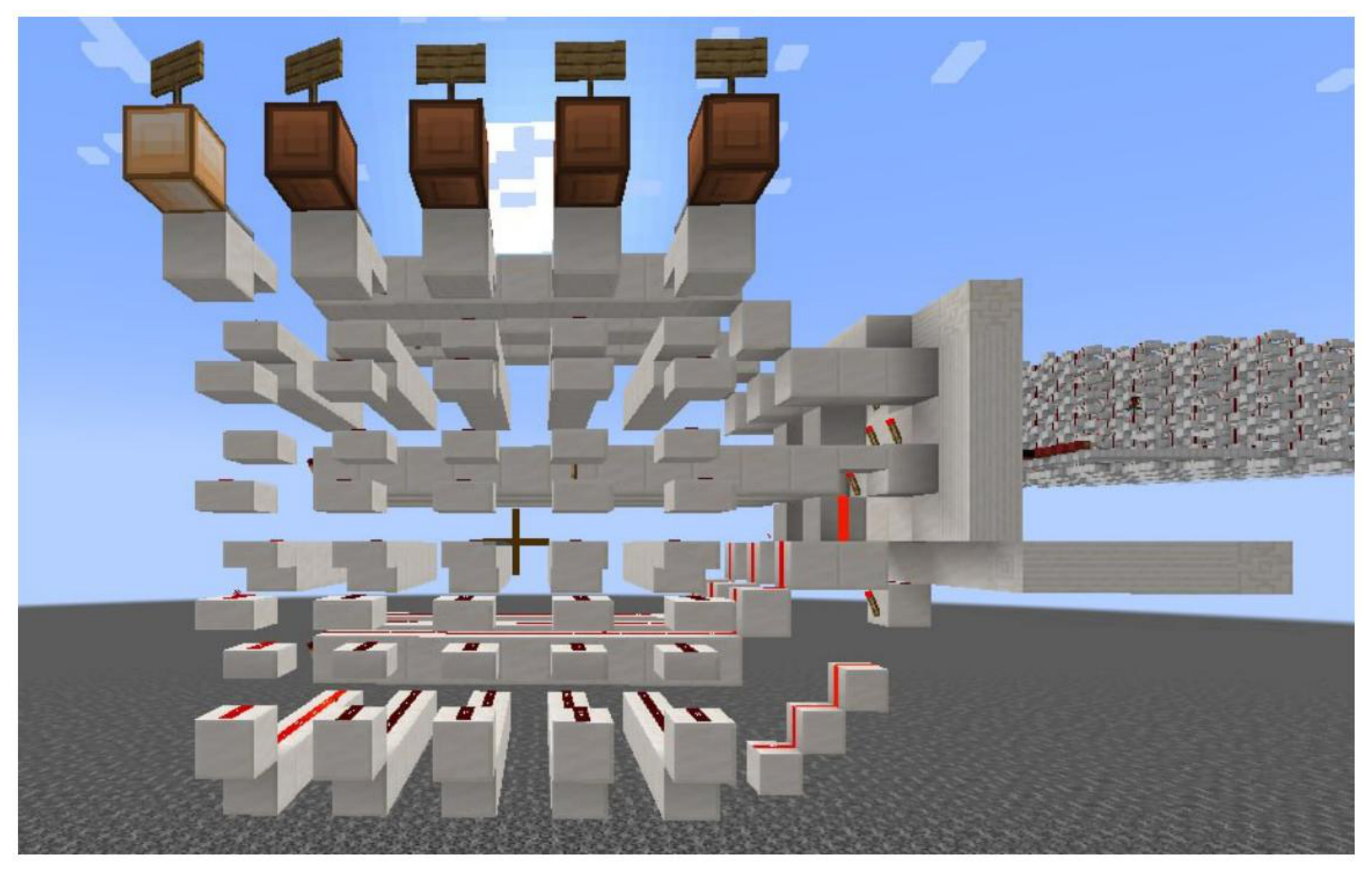
Figure 3.
Primary 8-bit ripple-carry binary full-adder ALU configuration.
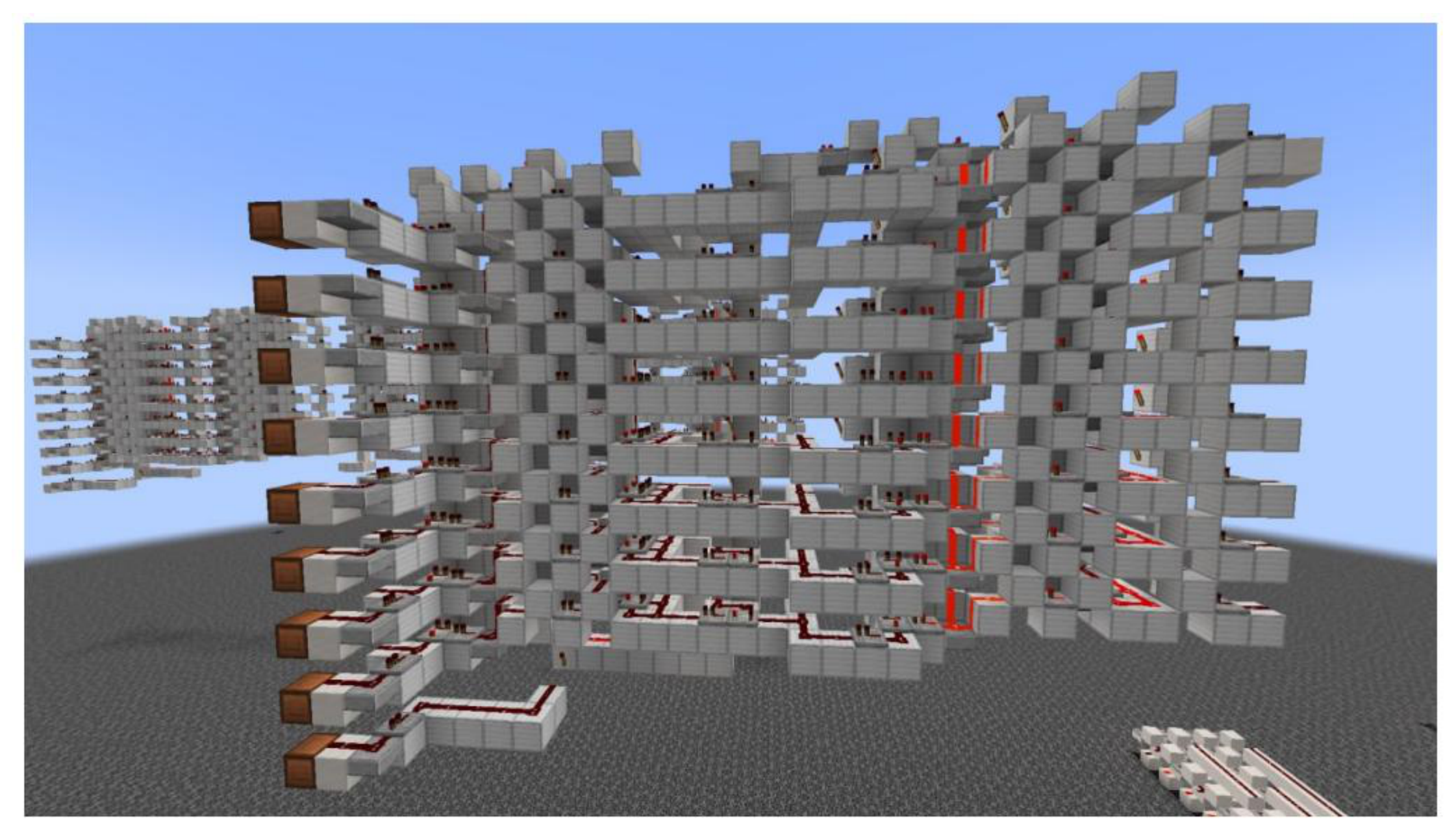
Figure 4.
Binary-to-BCD decoder subsystem array.
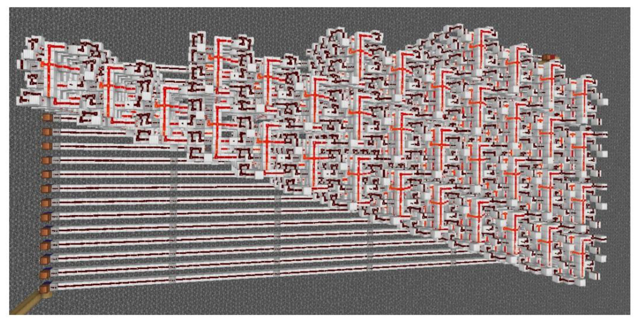
Disclaimer/Publisher’s Note: The statements, opinions and data contained in all publications are solely those of the individual author(s) and contributor(s) and not of MDPI and/or the editor(s). MDPI and/or the editor(s) disclaim responsibility for any injury to people or property resulting from any ideas, methods, instructions or products referred to in the content. |
© 2026 by the authors. Licensee MDPI, Basel, Switzerland. This article is an open access article distributed under the terms and conditions of the Creative Commons Attribution (CC BY) license (http://creativecommons.org/licenses/by/4.0/).
Copyright: This open access article is published under a Creative Commons CC BY 4.0 license, which permit the free download, distribution, and reuse, provided that the author and preprint are cited in any reuse.