

Submitted:
18 September 2026
Posted:
20 September 2026
You are already at the latest version
Abstract
Almost every proposal about the Great Pyramid is a proposal about the lift. Straight ramps, spiral ramps, ramps folded onto the faces, levers, rockers, counterweights sliding down the Grand Gallery: the argument is always about how a block travelled the last hundred and forty metres. This paper asks a different question. If the whole chain from the quarry face to the setting crew is simulated as coupled state machines, with each stage given a fixed crew and the calendar left to emerge, which stage actually sets the pace? The instrument is a twin of the building process, not a survey model of the building. The answer is the quarry, and it is not close. In every configuration that finishes inside Khufu’s reign, the lift has spare capacity on roughly nine working days in ten: it could have raised more stone than the quarry delivered. Three consequences follow. First, the admissible builds are not a scatter of estimates but a single curve: quarrymen multiplied by extraction rate must equal 283 cubic metres of finished block a working day, and the Giza quarry’s own frontage truncates that curve at 0.047 cubic metres per man-day. Below that rate there is no face for the men to stand on. The one experimental rate in the literature, about 0.05 cubic metres of block per man-day from copper-tool trials at Wadi el-Jarf, sits on that floor. The floor rests on an estimate of the working frontage, 4,000 metres at 1.5 men to the metre, which is a construction of ours and the most fragile number here; the qualitative claim survives across a wide range of it, the precise figure does not. Second, because the lift has slack, the schedule cannot choose between lifting schemes. A multi-ramp, tongues of laid block, and a straight ramp stopped at twenty-five metres all reach the capstone within three months of one another, and a steeper ramp saves earthwork without saving a single day. The one exception is the speed of a lever station: above roughly thirty minutes a block a course, no number of lever crews finishes the pyramid, which rules out cribbing at Isler’s measured rate while leaving the rocker and the A-frame comfortably inside the reign. There is a deeper reason the calendar is powerless here. The gravitational work of assembling the pyramid is about 2.1 TJ, which is under two per cent of the labour the site actually fields, and about seven per cent once sledge friction is included. No lifting machine can save more than that, and a counterweight cannot save even that, because a pyramid is a one-way flow of mass upward and there is nothing to send down to reset it. Third, what does discriminate is not the calendar but the spoil. The schemes that agree on the schedule differ by five orders of magnitude in ramp fill, from nothing at all to 5.38 million cubic metres, and Lehner has already proposed the test: the debris now filling the Khufu quarry may be the dismantled ramps. Nobody has measured its volume. We set out what that measurement would settle. Simulation invites thinking and validation. It is not a proof in itself.
Keywords:
Great Pyramid
; Giza
; construction logistics
; discrete-event simulation
; digital twin
; ramp hypotheses
; quarrying rate
; Old Kingdom
; bottleneck analysis
; experimental archaeology
1. Introduction
The literature on the Great Pyramid is a literature about lifting. Herodotus reported machines of short timbers [14]. Diodorus reported ramps [10]. The modern argument has run through the straight ramp, the spiral wrapped around the faces, the internal ramp, the zigzag of tongues laid course by course, levers and cribbing, rockers, and most recently counterweights running down the Grand Gallery [25]. Each proposal is judged on whether a block can plausibly be raised by the mechanism, and then on whether the mechanism is fast enough for twenty years.
This is a reasonable way to argue about a machine. It is a poor way to argue about a construction site. A site is a chain, and a chain does not go at the speed of any one stage. It goes at the speed of its slowest stage, and every other stage stands and waits. If the lift is not the slowest stage, then all the ingenuity spent on the lift buys nothing, and no comparison of lifting schemes on the calendar can tell them apart.
The present paper tests that possibility directly. The whole chain is modelled, from the two sources of stone that Figure 1 lays out: the local quarry with its finite working face, the Tura casing quarry, the Nile fleet, two sledge hauls, the lift, the setting crews laying casing as the leading edge of each course, and the camp with its support roll. The model is a deterministic discrete-event world of coupled state machines, in which each stage publishes what it has done and the rest of the chain reprices on the news. What is new here is not the machinery but the question put to it. Instead of imposing a pace and reading off the headcount, we fix the crews and let the calendar emerge. That inversion is what makes the binding stage visible.
Section 2 describes the model and the method. A logistics model can be run in two ways. In the first, a target pace is imposed and each stage is sized to meet it, which is how most published estimates are built and which can never show a bottleneck, since every stage has been made adequate by construction. In the second, the crews are declared and the completion date is left to emerge, together with a record of which stage was waiting for which on every working day. Only the second can locate a constraint, and every claim in this paper about what binds is made in that mode. The section also sets out how the crews are chosen so that the headcount reported is the one the schedule requires rather than the one the modeller typed. Section 3 derives the relation that every twenty-seven-year build must satisfy between quarry headcount and extraction rate, and shows that the published estimates already satisfy it, mostly without saying so. Section 4 locates the slack and answers the rival claim that the bottleneck shifts with height. Section 5 compares the lifting schemes on the calendar, and Section 6 shows why the calendar cannot separate them: raising the stone is only a few per cent of the labour, which bounds the value of any lifting machine and disposes of the counterweight proposals on their own terms; the same section prices the granite, the hardest handling problem on the site and a negligible one for the schedule. Section 7 gives the one quantity the schedule does discriminate, the lever rate at the top, and Section 8 gives the arithmetic of the corner. Section 9 separates the camp from the population. Section 10 turns to the measurement that would settle the rest, and which nobody has made. Section 11 sets out what this does not establish.
2. The Model: Pace Versus Crews
2.1. The World
The site is eight coupled state machines on a deterministic discrete-event engine. Time advances in day ticks. Each machine holds its own state, accepts actions, publishes a projection, and carries invariants that must hold in every state the run reaches. An invariant that fails does not degrade the statistics. It stops the run and names the day, the course and the reason. That is how an impossibility is reported here: not as a long tail in a distribution, but as a refusal at a named course.
The geometry is Petrie’s, 210 courses to 146.6 metres on a 230.3 metre base [21]. In the units the work was laid out in, that is 280 cubits of height on 440 of base, a seked of five and a half palms to the cubit, and we give cubits alongside metres wherever the argument turns on the monument’s own proportions.
The bill of materials is 2,232,989 core blocks and 64,070 casing blocks. Petrie’s table gives course heights, not block counts, so the step from one to the other is ours: each course is filled with blocks of its own thickness and of a mean plan of 1.3 by 0.9 metres, which reproduces the conventional estimate of about 2.3 million blocks and gives a mean block of 1.10 cubic metres, about 2.5 tonnes. The geometric envelope of the monument is 2.59 million cubic metres; the blocks account for 2.52 million, the rest being mortar, chips and voids, and every volume in this paper is the block volume unless it says otherwise. Two consequences follow. Blocks get smaller as the pyramid rises, from 1.54 cubic metres in the first course to 0.60 in the last, and, as Section 11 concedes, an extraction rate expressed per cubic metre is therefore not scale-invariant. And the model treats the core as one material, which the monument does not: Khufu’s core masonry is of very uneven quality, with coarse blocks and thick joints packed with mortar and chips, and neither its extraction nor its setting cost what the fine lower courses cost [20].
Cutting those blocks removes more rock than the blocks contain, because the channels between them are cut to waste. At AERA’s estimate of thirty per cent channelling waste, itself a master carver’s judgement rather than a measurement, the finished blocks represent 2.52 million cubic metres of stone and the extraction is 3.59 million cubic metres of rock.
The casing is set as the leading edge of each course rather than dressed on later, which is Arnold’s reading of the evidence and Lehner’s [9]. It is not unanimous, and it matters here only in that it puts Tura’s deliveries on the critical path of every course rather than at the end of the build.
The calendar is nine working days in ten, the decan week, giving 328.5 working days a year, and a ten-hour working day. These are conventional and they matter: every rate in this paper is per working day, not per calendar day, and the difference is eleven per cent.
The quarry has two properties that turn out to carry the argument. It has an extraction rate per man-day at the face, which is the least constrained parameter in the whole literature, and it has a finite working face. The horseshoe quarry south of the pyramid offers of the order of 4,000 metres of face across its benches, and a metre of face employs about one and a half men, one in the channel and half a man levering and clearing behind him. That gives 6,000 places. A crew larger than that has nowhere to stand. The figure is a modelling choice built from AERA’s description of the quarry rather than a measurement, and Section 11 says what would sharpen it.
2.2. Target Mode and Fixed Mode
There are two ways to ask a logistics model for a number, and they are not equivalent.
In target mode the pace is imposed. One declares that the site lays 254 blocks a working day, each stage sizes its own crew from its own physics to meet that pace, and the model reports the headcount that results. This is how most published estimates are constructed, whether or not they are called simulations, and it is how our own earlier work on this world was constructed. It answers the question “how many men does this pace require”.
In fixed mode the crews are declared and the calendar emerges. One states that there are 2,830 quarrymen, 1,000 haulers on the core sledges, 720 setters and so on, and the model reports how long the pyramid takes and which stage was waiting for which. It answers the question “what does this site do”.
The distinction is not a technicality. In target mode no stage can ever be the bottleneck, because every stage has been sized to the pace by construction. A target-mode model can tell you that a configuration is expensive or that it is geometrically impossible. It cannot tell you which stage sets the pace, because the pace was an input. Every statement in this paper about what binds is a fixed-mode statement, and the numbers differ from the target-mode ones in ways we flag where they arise.
2.3. The Balanced Site
Fixed mode has a trap of its own. If crews are set carelessly, the answer reports the carelessness. Staffing every stage by scaling one common factor, overstaffs most stages and inflates the camp. In our case it also produced a spurious result: six boats working against a slower site piled 46,488 casing blocks on the plateau, a stockpile of seven hectares, which we briefly took for a finding. Three boats deliver the same pyramid on the same date with 18,885 blocks in the yard. The stockpile was an artefact of our staffing, not a fact about Giza.
The remedy used throughout is a balanced site. Take one stage at a time, try the next smaller crew, rerun the entire build, and keep the smaller crew if the completion date does not move by more than one per cent. Otherwise put it back and go on to the next stage. Repeat until no single reduction is free. What survives is the smallest site that holds the pace, so the headcount reported is the one the schedule requires rather than the one the modeller happened to type.
Two caveats. The search is greedy and one-dimensional, so it finds a local minimum; two crews might come down together where neither comes down alone. And the one per cent tolerance is a choice. The ladders are coarse on purpose, because the relevant range is factors of two, not single men.
A balanced site is balanced for a given duration. It therefore cannot go much faster than that duration, and one must not read its inability to do so as a physical floor. We report one such near-miss in Section 11.
2.4. The Fleet Against Merer’s Journal
Almost nothing in this model can be tested against a document. The fleet can. Merer’s journal supplies the date and three of the fleet’s parameters, so the check is made explicitly.
The diary gives a boat’s load, put by Tallet at about thirty blocks; a round trip of the order of four days, from the pattern of nights spent at Tura and at the basin; and laden voyages only while the flood allowed them [27]. Those are the values in our barge machine. The check is whether they close.
A flood of 110 days is 99 working days, so a boat makes about 25 round trips a season and carries some 742 blocks. Three boats carry 2,228 a season and 61,256 over 27.5 years, against the 64,070 casing blocks the monument needs. That is short by 4.4 per cent, which is to say the diary’s own cadence asks for 3.14 boats.
We take that as a pass. Three boats on Merer’s rhythm very nearly deliver the skin of the pyramid inside the reign, and four deliver it with slack. It is the only place in this study where a contemporary record and a simulated stage can be laid against each other, and they agree to within one boat.
2.5. The Baseline
With the site balanced at an extraction rate of 0.10 cubic metres of block per man-day, the build takes 27.5 years with 8,100 men on the stone and a camp of 9,678 including the support roll. The crews are 2,830 quarrymen, 3,110 on the lift, 1,000 on the core sledges, 720 setting, 180 at Tura, 140 on the casing sledges and 120 on the boats. The ramp fill raised and later removed is 44,181 cubic metres. Figure 2 shows the chain.
That duration is within a few months of the twenty-seven years we have assumed, for the reasons and with the caveats set out in Section 3.
3. The Quarry Constraint
3.1. The Hyperbola
Fix the duration and the arithmetic of the quarry collapses to a single number. The pyramid needs 2.52 million cubic metres of finished block. A build of twenty-seven and a half years at 328.5 working days a year has roughly 9,040 working days. The quarry must therefore deliver about 283 cubic metres of finished block a working day, which is 404 cubic metres of rock removed once the channelling waste is counted.
The rules that the rest of the paper turns on are set out in boxes as they arise, each stated first as the master of works might have put it and then as we write it, and they are referred to by number afterwards.
Rule 1. Count the block in the pyramid. Count the days the king gives you. What the quarry must yield each day is the one divided by the other, and it does not care how you lift.
In the model the quarry’s daily output is its headcount multiplied by its extraction rate. So the constraint is a product:
Rule 2. Men at the face times what each man cuts in a day must equal that yield. Choose how many men and you have chosen how fast they cut. Choose how fast they cut and you have chosen how many men.
This is a hyperbola in the plane of headcount against rate, and Figure 3 draws it. It says that the two quantities the literature argues about separately are not independent at all. Given the reign, choosing one chooses the other.
3.1.0.1. Duration.
Three quantities have to be kept apart, and the literature, ourselves included, has run them together. The Turin Canon gives Khufu twenty-three years. The Wadi al-Jarf papyri are dated to the year after the thirteenth cattle count, conventionally regnal year 26 or 27, which establishes only that the reign reached at least that far. And what Merer records in that year is the carriage of Tura limestone, which is casing, and therefore work that belongs late rather than early. None of the three is a statement about how long the building took. The core may have been substantially up before Merer wrote, and work may have begun before the accession.
We have therefore stopped calling 27.5 years Merer’s. It is our assumption, and the constant in Rule Section 3.1 scales with it, as Table 1 shows:
Nothing qualitative changes across that range. A rate of 0.02 is refused at every duration, since it needs 14,000 men at all three. What moves is the floor, from 0.047 to 0.065, and any reader who prefers the Turin figure should read 0.056 wherever we write 0.047. The experimental rate of Burgos and Laroze, about 0.05, sits on the floor at our duration and just below it at the Turin one.
3.2. The Face Cap and the Floor
The curve is unbounded in the abstract. A slow face can always be answered by more men. It is not unbounded at Giza, because the men have to stand somewhere. At 6,000 places the face saturates, and Rule Section 3.1 then requires a rate of at least cubic metres per man-day.
Rule 3. A man needs a place to stand. The face is so many cubits long, and one man and a half to each two cubits. That is the most men the quarry will take, and it sets the slowest cutting that can build the pyramid in time.
The floor moves as . A longer face admits a slower man; the duration does not change.
Table 2 is the simulated version of that statement. Each row staffs the quarry on the curve, staffs Tura in proportion, leaves every other crew at its balanced value, and runs the whole build.
Two features of that table matter.
The first is that the duration column is flat. This is not a coincidence and it is not circular. The quarry was staffed to the curve precisely so that the duration would be held constant; the table’s content is the cost of holding it, in men, and the fact that at four rates the cost cannot be paid at all.
The second is the shape of the failure. The refusal at 0.04 and below is not “the build takes too long”. It is an invariant stopping the run because the crew the pace requires has no face to stand on. A rate of 0.02 cubic metres per man-day would need 14,150 men at the Giza face. That is a geometric refusal, and it is the only kind of refusal in this paper that does not depend on how the rest of the site is staffed.
The one experimental rate falls as follows. Burgos and Laroze cut limestone with copper tools at Wadi el-Jarf and report about 0.021 cubic metres of channel an hour once the rock is wetted, and about 0.05 blocks per worker per day when channelling, levering and dressing are all charged [5]. In the units of Rule Section 3.1 that is of the order of 0.05 cubic metres of block per man-day. It sits on the floor, not below it: at our face cap it is admissible with a camp of 13,290, and it is the row of Table 2 marked with their name.
3.2.0.2. Sensitivity to the face cap.
Since the floor is 283 divided by the places at the face (Rule Section 3.2), everything turns on how much face can be worked at once, and that is a number nobody has measured. We reran the rate table at several caps, staffing the quarry to the curve each time. Table 3 is the result. The duration never moves; the cap decides only where the table is cut and what the camp costs below the old floor.
Two things follow. The mechanism is robust: at any cap the face truncates the curve, and the site that would be needed below the floor grows without limit. The precise floor is not robust, and the paper does not claim it is. In particular, AERA’s description of the quarry is of corridors “the size of hotel corridors” isolating large masses of bedrock, which are then subdivided by channels just wide enough for one man. A grid of that kind exposes face on every side of every isolated mass, so the workable frontage per unit of quarry is larger than a perimeter walked along its benches. Our 4,000 metres is therefore a floor on the frontage, and 0.047 an upper bound on the true floor. What that bound costs is visible in the table: every step down in the floor is a step up in the camp.
Just below the floor the failure is graded rather than abrupt, because a slower face simply takes longer. With the face full at 6,000 men rather than staffed to the curve, which is what the refused rows of Table 2 attempt, a rate of 0.047 gives 27.6 years, 0.045 gives 28.7, 0.044 gives 29.3 and 0.040 gives 32.0. The reign is the thing that turns a slow build into an impossible one.
3.3. The Workforce Band
Because the non-quarry stages are staffed to a pace that does not change, they do not change either. Across the whole admissible family they sit at about 5,300 men. Everything that varies in the camp column of Table 2 is quarrymen and the support roll that follows them. Figure 4 shows this directly.
A camp figure is a scribe’s unit and not a builder’s. Merer’s own team was about forty men. The 8,100 on the stone at the baseline is therefore of the order of two hundred such teams, and the camp of 9,678 about two hundred and forty. That is the size of thing an overseer would have added or removed, and it is a better way to read the band below than a number to the nearest man.
The result is a workforce band of 7,500 to 13,700 for the entire admissible range of extraction rates. That is much narrower than the literature’s spread of a factor of ten, and it brackets Hawass’s 10,000 [13] and reaches the lower edge of the Lehner and DMJM band [24]. The band is narrow not because we have measured anything the field has not, but because fixing the reign and balancing the site removes most of the freedom that the spread was made of.
3.4. Published Estimates on the Curve
The most useful thing about Rule Section 3.1 is that it is not ours. Any quantitative proposal that names a duration and a quarry crew has implicitly chosen an extraction rate, whether or not it says so.
De Haan’s levering study is the clearest case [7]. He builds the pyramid in twenty years at 2,624 working hours a year, at an average of 50 cubic metres an hour, and staffs the opening phase with 2,077 quarrymen in his base case and 2,805 in his maximum case. Work his own numbers and the quarry is producing about 399 cubic metres of block a working day from 2,077 men. That is an extraction rate of 0.19 cubic metres per man-day. It is nowhere stated, nowhere justified, and it is twice the rate we adopt as a baseline and four times the Giza floor. It is a defensible figure. De Haan is not wrong; the most sensitive parameter in his model is invisible in it.
His maximum case opens with 2,805 quarrymen, within one per cent of the 2,830 our balanced site needs at 0.10. Two models built seventeen years apart, on different principles, converge on the same quarry crew, and differ by forty per cent in the rate they silently assume, because they differ in the duration they assume.
Table 4 makes the reading explicit. For each quantitative proposal we take the duration it assumes and the quarry crew it names, and report the extraction rate those two imply. Only one of the rates in the last column was actually stated by its author.
Rosell Roig’s recent multi-ramp study is the other quantitative model in the field [22]. It models quarrying as a separate phase of 15.7 to 21.5 years and gives 20 to 27 years for the whole undertaking, which places it on the same curve at the lower end of our admissible band. Scheuring’s counterweight proposal [25] names the required placement rate of one block a minute and models neither workforce nor supply, so it is a scheme with no position on the curve at all. We return to that pair in Section 5, because together they make the argument better than we could.
4. The Binding Stage
4.1. Daily Binding Limits
The model records, for every working day, which limit was active: the number of hauling teams, the headway between sledges on a lane, the lever stations, or none of these, meaning the lift had capacity to spare and was short of stone.
At the baseline, the lift had capacity to spare on 8,101 of 9,040 working days. Hauling teams were the active limit on 725 days, lever stations on 214, and lane headway on none. For ninety per cent of the build the machine everyone argues about was running below its own capacity, waiting for the quarry. That is not a statement that the crews were idle: the lift worked every working day. It is a statement about which stage set the day’s output.
Rule 4. The pyramid rises at the pace of its slowest gang. Nine days in ten that gang is at the quarry. Make the ramp better and you will finish on the same day. Make the quarry better and you will finish sooner.
B is the block count, the blocks one lane dispatches in a day (Rule Section 5.1.0.7).
Figure 5 shows the same accounting for three schemes. The tongues of laid block are starved on ninety-seven per cent of days. The multi-ramp on ninety. The one scheme that is materially limited by itself is the single straight ramp, and its limit is lane headway (Rule Section 5.1.0.7): two lanes cannot dispatch blocks fast enough, so it spends twenty-six per cent of the build waiting for its own lanes rather than for stone.
4.2. The Shifting-Bottleneck Hypothesis
The most serious rival to this reading is Rosell Roig’s, which does not claim the lift binds but claims the bottleneck shifts: width-constrained early, when many lanes can be fed, and height-constrained late, when the face has no room for them [22]. That is a plausible mechanism.
The answer is that in our accounting the shift does not happen. The starvation is not concentrated at one end of the build. It is distributed across it, and the height-limited regime that should dominate the top of the pyramid shows up as 214 lever-limited days out of 9,040, two per cent. The reason is straightforward: the top sixth of the height is about half a per cent of the volume, since the volume above a height h goes as . Even a slow mechanism up there has very little stone to move. Height constrains the method near the apex, decisively, as the failure of the spiral and the unassisted multi-ramp shows. It does not constrain the schedule, because there is almost nothing left to lift.
There is one place where our accounting agrees with the shifting picture. The straight ramp is width-limited, in the specific sense that its two lanes are its binding constraint for a quarter of the build. Width is a real constraint on that scheme. It is not a constraint on the schemes that fold the ramp onto the faces, because they have five to sixteen lanes.
5. Lifting Schemes on the Calendar
If the lift has slack on nine days in ten, then improving the lift cannot shorten the build, and comparing lifting schemes on the calendar cannot choose between them. This is the central negative result, and it is easy to overstate.
Table 5 is the result. Four schemes finish within three months of one another, and a fifth, levers alone, finishes five months behind them at the fastest lever rate and not at all at a slow one (Section 7). They are not variations on a theme: one raises no fill at all, one raises 44,181 cubic metres, one raises 130,000. The schedule does not distinguish them because none of them is what the site is waiting for.
Three sensitivities make the same point from different directions.
5.0.0.3. Grade.
The grade of the ramp is one of the most argued quantities in the field, and it has often been pressed that a steeper ramp is enormously more efficient in earth moved. That case is correct, and it buys nothing in time. Between 1:10 and 1:2 the duration moves from 27.52 to 27.26 years, a quarter of a year, while the fill falls from 44,181 to 8,836 cubic metres, a factor of five. Figure 6 shows both panels. A steeper ramp is a better ramp. It is not a faster pyramid, because the ramp is not the binding term of Rule Section 4.1.
5.0.0.4. Where levers take over.
Similarly for the height at which the ramp stops and levers begin. This series was run with the lever stations staffed generously, at 240 crews, so that the lever stage never binds and only the switch height moves; that is why its 100 metre point reads 27.47 years rather than the baseline’s 27.52. Taking over at 100 metres gives 27.47 years and 44,181 cubic metres of fill. Taking over at 25 metres gives 29.55 years and 24,700 cubic metres. That is a real trade, two years of schedule against nineteen thousand cubic metres of earth, and it is the only place in this study where the two currencies are exchanged at a rate a planner would have had to think about. Figure 7 shows it.
5.0.0.5. Combinations.
Because the phases can be composed, we also ran mixed schemes: a straight ramp to 25 metres and then a multi-ramp, a straight ramp and then tongues, each finishing with levers. They finish on the same dates as their unmixed counterparts. There is no combination in this family that is faster than its parts, which is what one expects once the quarry is the constraint. The interest of combinations is entirely in the earthwork and in the practicalities of the first twenty-five metres, where a straight approach is easy and cheap.
Scheuring’s counterweight scheme and Rosell Roig’s sixteen ramps are, in this light, a matched pair. They are mutually exclusive accounts of how the stone was raised. Both fit the reign. Neither is tested against a quarry budget. That two such different machines can both satisfy the schedule is not a weakness of either paper. It is evidence that the schedule is not the discriminating measurement.
5.1. Stepped Tongues: Routes and Faces
One scheme in Table 5 is treated separately, because it performs best on the criteria this paper can measure and because the simulation suggests a refinement that the published reconstruction does not contain.
Choi’s reconstruction [4] builds the ramp out of the pyramid itself: straight inclined tongues of laid block on the faces, climbing one step at a time, with the surplus carved away at the end. On the three things we can measure it does well. It raises no fill at all, alone among the schemes tested, because the ramp is the monument and there is nothing to import and nothing to remove but block. It finishes marginally fastest of the family, 27.26 years against 27.52 for the multi-ramp. And it is the scheme for which the corner question of Section 8 is least severe, though how it is answered depends on a detail the published frames leave open. A sledge arriving at the head of a tongue can be turned at a post and sent back along the next tongue, which is the zigzag Figure 8 draws, or it can be shifted laterally on the terrace to the foot of a tongue continuing in the same heading, in which case it is never turned at all. Both are consistent with the frames, both are consistent with everything this paper measures, and the choice between them belongs to the companion paper on ramp design. Where this paper needs a number it takes the zigzag, because that is the case in which the corner binds; the lateral shift can only be easier.
5.1.0.6. Tongue, route, lane.
The model counts lanes and the construction frames draw ramps, and the discussion has been sloppy about the difference. We fix it here.
A tongue is one inclined ramp of laid block climbing one step on one face: a physical object, with a length, a width and a grade. A route is a connected sequence of tongues from the ground to the working level: the path a stone actually takes, reversing at a post at the head of each tongue. A lane is neither of those. It is a parallel dispatch channel, the unit throughput is counted in: one more lane means one more block can be started at the same moment.
The relation between them is the thing to hold on to. A route is a pipeline. Many stones are on it at once, spread over its tongues, but they leave its foot one at a time, so a route however long carries one lane. Two lanes on one route is possible, and it means only one thing: a tongue wide enough for two sledges abreast, with the terraces wide enough to hold both at the reversal. Otherwise more lanes means more routes.
5.1.0.7. Lanes required.
At a four-minute dispatch headway a lane starts 150 blocks in a ten-hour day. The quarry sustains 254. The whole site therefore needs 1.7 lanes, which is to say two, and it needs two at every height, because the quarry’s output does not taper as the pyramid rises. What tapers is the work left to do.
Rule 5. One track sends off a sledge as often as the men can clear it. Count the sledges a track sends in a day. Divide the day’s blocks by that, and you have the tracks you need. You need them at every height.
5.1.0.8. Lanes per face.
Lanes are spaced about 14.4 metres apart on a face. That figure is a pitch between parallel routes, the track together with the working room beside it for the crew, and it is the spacing the lane counts in this section use throughout. The 3.8 metres of Section 8 is the width of the track alone, which is why that section finds a lane still fitting at 144.6 metres where this one finds none above 137.6. Figure 9 puts the supply against the demand. At the base one face holds fifteen lanes, nine times what is needed. At 100 metres it holds five. At 120 metres, two. At 128.6 metres it drops to one and the lift begins to fall behind the quarry. At 137.6 metres no lane fits on a face at all, and 1,087 blocks remain above that, which is the region Section 8 is about.
Rule 6. A face at any height is so many cubits wide. A track with its men beside it takes so many cubits. Divide, and you know how many tracks that face will carry. Higher up, fewer.
At the base, 15 lanes. At 100 m, 5. At 120 m, 2. At 128.6 m, 1, and the lift falls behind the quarry. At 137.6 m, none.
5.1.0.9. Measured tongue widths.
The calculation above used a lane spacing taken from the modelling literature. The widths in the construction frames of [4] are better evidence than that spacing, because they are a reconstruction of the ramp rather than an assumption about the face, and we now use them.
Below the level of the King’s Chamber the frames make the tongue about nine metres wide and put roughly a hundred men on the rope in four files. Above it the tongue narrows to under four metres and the crew falls to thirty or forty in two files, because the blocks up there are lighter. A nine metre tongue holds two lanes; a four metre tongue holds one.
That single change produces a two-regime site. Below the King’s Chamber, which is 54.6 per cent of the blocks, one route at two lanes starts 300 blocks a day against the 254 the quarry sustains, so one route is enough. Above it, one route at one lane starts 150, and the lift falls behind.
Rule 7. Below the King’s Chamber the tongue is seventeen cubits wide and a hundred men pull in four files: two sledges abreast. Above it the tongue is seven cubits and thirty to forty men pull in two files: one sledge. Below, one route feeds the quarry’s whole yield. Above, you need a second.
Carried through the whole build, Table 6:
The ideal is simply the block count divided by the quarry’s daily output, 2,297,059 blocks at 254 a day, and it is the day count of a lift that never falls behind. One route below and two above hits it exactly. One route throughout costs 2,848 working days, which is nearly nine years, and it is the only configuration in this study where the lift binds. This table counts routes, not faces: the second route above 43 metres can be a second tongue on the same face.
The ramp narrows where the stone gets lighter, so lanes per route halve just as the work would otherwise get easier, and the site has to answer by doubling the routes. The hybrid is real, the switch is at the King’s Chamber, and it runs upward: fewer lanes to a route higher up, therefore more routes.
5.1.0.10. Faces.
The published reconstruction begins on all four faces and sheds them as the pyramid narrows. The arithmetic says the opposite. The question here is faces rather than routes, so the count reverts to the 14.4 metre pitch, which is what fixes how many routes a face can hold at a given height. One face is over-supplied by a factor of nine at the base and is still sufficient at 128 metres, by which point 99.7 per cent of the blocks are laid. Putting a route on a second face first buys anything at course 174, and a third and fourth buy nothing at all, because above that height each face holds one lane and two faces already give two.
Costed over the whole build, one face takes 9,063 lifting days and four faces take 9,044, the ideal. The other three faces are worth twenty working days in nine thousand, two tenths of one per cent, and they cost three times the overbuild. That is the discrimination, and it does not go the way the drawings do.
Table 7 confirms it in the simulation, which prices the whole chain rather than the lift alone, and Figure 10 shows the surplus block falling with the number of faces used.
Four routes deliver the pyramid on exactly the same date as sixteen, with not a single working day lost to lane headway. Three begin to bite, at 108 days. Two cost a year and a month. One cannot do it. So the system’s capacity is needed, but only about a quarter of what is drawn: the useful range is three to four routes, and where they are put is free.
That has a consequence for the overbuild, and it is a large one. The tongues are surplus block that has to be cut, raised and then taken down again. Carried around the whole monument to a frustum with an 80 metre top side, the surplus is 1.54 million blocks and 1.21 million cubic metres, which is 47 per cent of the pyramid’s own volume handled twice. Restricted to the faces that actually carry traffic, it falls in proportion: about half for two faces and about a quarter for one, some 300,000 cubic metres. Since the schedule is identical either way, the logistics argue for the smaller deployment. The mechanism is that of [4]; what the model suggests is that it was not needed on every face.
Two caveats, one for the full overbuild and one against it. For it, a partial overbuild is architecturally harder than a symmetric one, since the courses must be laid to two different profiles on different sides, and the reason to build all four faces alike may have had nothing to do with logistics. Against, even a quarter-scale overbuild is 386,000 blocks that come down, and they have to go somewhere. Giza is not short of other Fourth Dynasty construction that could have absorbed them, and tracing where a descending block went is a more promising question than arguing about whether it descended.
5.2. The Underbuild
Section 5.1 costs a scheme that builds outside the finished surface and cuts back to it. The inversion is to build inside the finished surface and fill out to it. It is cheaper on every measure this paper can apply. Building from the inside out is not new: [2] proposes a pyramid raised by accretion, each course added as a peripheral layer around a core, with the blocks levered rather than hauled. The underbuild below shares the geometry and not the lifting; the lifting is costed in Section 7.
Let the core be a step pyramid, and let its terraces be the road. Nothing is imported and nothing is surplus: the steps are the monument. The shell is added afterwards, burying the road. We first describe the version in which it is completed from the summit downward, so that the part of the road still needed is always the part below the work; the evidence discussed at the end of this section will turn out to favour a shell rising from below and closing the road level by level, and the material budget is the same either way. Figure 11 shows the arrangement.
Before the arithmetic, a caution. That stepped cores were built is certain: Meidum shows one where the casing has fallen away, and Djoser’s monument is the idea carried to its conclusion. That Khufu’s core is built that way is a different proposition, argued for a century without a decision because nobody can see inside it [20]. What is observed is a set of thicker girdle courses at intervals, which some read as accretion markers and others as ordinary coursing. What follows is a logistical assessment of a contested architectural hypothesis, not a description of the monument.
The geometry is best seen in the units the work was set out in. The pyramid is 440 cubits on 280, a seked of five and a half palms to the cubit, so a step of rise R sets back by exactly . The terrace it leaves is that wide, and because the seked is constant the road is the same width all the way up. In metres this is the cotangent of 51.84 degrees; in cubits it is the design rule the master of works actually applied.
Rule 8.Each step of the pyramid rises so much and sets back by five palms and a half for every cubit it rises. The ledge it leaves is that wide, and it is the same width all the way up. Build your tongues on the risers and your turns on the ledges.
Table 8 is the consequence. Only a step rise that is a multiple of seven cubits produces a terrace in whole cubits, and of those, only a core of twenty steps of fourteen cubits gives a road both integral and wide enough to work: eleven cubits, which is 5.8 metres. Forty steps of seven cubits gives five and a half cubits, too narrow for the 7-cubit lane the recent modelling literature adopts. Nothing about this was arranged by us; it falls out of the seked.
The shell left to add is a small fraction of the whole. For N steps the inscribed stepped solid is short of the smooth pyramid by about of its volume, which is 194,000 cubic metres at 20 steps and 130,000 at 30. That material is not surplus. It is core packing and casing the pyramid needs in any case, so it is handled once. Set against the alternatives, Table 9:
On the schedule it is the four-lane row of Table 7: one route on each of the four faces, switching back along the terraces, is four lanes, and four lanes (Rule Section 5.1.0.7) deliver the pyramid in 27.26 years with no day lost to headway. The capacity the geometry hands you is exactly the capacity the quarry can feed.
5.2.0.11. Objections.
We put this scheme to a language model and took its four objections seriously. Three are answerable and the fourth is not, and the fourth is the one that matters.
The first is that moving a block from one step up to the next is unresolved and would need pulleys Old Kingdom Egypt did not have. This misreads the scheme. The steps are not bare: each riser carries a tongue of laid block, and a sledge is hauled up it as it is hauled up any ramp. There is no lift.
The second is that filling the shell from the top down would put the weight of the casing on voids or on temporary supports. This does not arise either, because in an underbuild there are no voids: the road is the top of the core, and the shell placed against the core face bears on completed masonry.
The third is that a finished surface cannot be fitted accurately working downward. This one has force, and it is the same reservation the architectural review raised. Setting out a surface from above is harder than setting it out from below, and the casing joints at Giza are the finest in Egyptian architecture. We do not have an answer.
The fourth is decisive and we should have found it ourselves. At Meidum and at Sekhemkhet, where the work stopped, the casing was reportedly going on over the stepped core from the bottom up. That is direct evidence about the direction of the finishing, from the only monuments that preserve it, and it runs against the downward reading. It also removes what was left of the Herodotus passage, which we had already demoted.
The conclusion is that the underbuild survives as a way of building the core and using its terraces as the road, which is the part the objections themselves called insightful and which sits close to Houdin’s internal-ramp proposal [18]. It does not survive as an account of how the casing was applied. If the terraces were the road, the road must have been buried by casing rising from below and closed off level by level as the shell overtook it, not by a shell descending from the summit.
Two things still recommend the core idea beyond the arithmetic. Stepped cores are attested, most visibly at Meidum. And the four mudbrick ramps found leaning against the core at Sinki, one to a face, are the same topology at small scale [9].
A third might be offered and should not be. Herodotus says the highest parts were finished first and the parts near the ground last of all, and it is tempting to read that as a description of this scheme. It is not evidence. Dressing a finished face proceeds downward under every reconstruction, including one in which the casing is set course by course going up, because a surface cannot be dressed from a scaffold standing on it. Top-down finishing is a necessity of the trade, not a signature of a stepped core, and an argument that rests on a late and demonstrably unreliable source when it does not need to is an argument weakened.
Three things count against it, and they should be said. The model does not implement it as a lifting theory of its own; we price it by its lane count and its material budget, which is enough to compare it but not to test it. Finishing a surface downward is harder to survey than finishing it upward, and the casing joints at Giza are the finest in Egyptian architecture, so the burden of proof is on the scheme rather than against it. And the corner limit of Section 8 applies here as everywhere: above about 120 metres the terraces are too short to turn a loaded sledge, whatever the road is made of.
5.3. Partial Overbuild
Overbuilding and underbuilding are not two theories. They are the two directions of one parameter, and the reconstruction of interest is neither extreme.
At any height the working profile can sit outside the finished surface, in which case the surplus is carved back, or on it, or inside it, in which case the deficit is filled later. Each has a price. Surplus is handled twice: cut, raised, and taken down again. Deficit is handled once, since it is material the pyramid needs anyway, and costs nothing but the deferral. On that accounting underbuilding wins everywhere and there is no reason ever to overbuild.
Except that overbuilding buys something, and Section 6.5 says what: area. A working profile outside the finished surface is wider at every height than the finished one, so the deck, the terrace and the turning room are all larger. Underbuilding does the reverse and brings the apex constraints down to bite lower.
That settles the shape of the optimum, because area is not scarce everywhere. It is abundant for the first 120 metres, where the side is over 40 metres and a loaded sledge can be swung round freely, and it is scarce only in the last twenty-five, where Table 12 shows every limit arriving at once. So the efficient profile is to build at or inside the finished surface for five-sixths of the height, and to step outside it only where the deck would otherwise become too small to work.
The saving is large. In the monument’s own units the finished side falls to 80 cubits at a height of 229, and 80 cubits, 42 metres, is comfortably the two crew lengths of 34.8 metres that Section 8 finds a sledge needs to turn, so a stub that wide keeps the turning room with a margin. A stub of 80 cubits square carried above that height contains 46,922 cubic metres against the 15,163 the pyramid itself has up there. The surplus to be carved away is 31,759 cubic metres. The frustum as drawn in [4], with an 80 metre top side carried the full height, has a surplus of 1,213,183. The stub is thirty-eight times cheaper and buys the same thing, because the only place the frustum was earning its keep was the top. Table 10 gives the range between the two.
Three further remarks.
The first is made in [4], and it is an argument for overbuilding that has nothing to do with area. It divides the proposals into additive and subtractive, and observes that almost all of them are additive: stones are placed where they will finally stand. The difficulty with that is precision. Four arrises have to stay straight over two hundred and eighty cubits and meet at a single point, and near the summit the working surface is a few metres across, which is where that book notes that the literature’s own reconstructions start needing helicopters. A subtractive finish removes the problem: an oversized mass can be cut back to a plane using sight lines taken from outside the monument, and the accuracy of the result depends on the survey rather than on the placing.
That argument and ours point at the same place. Area runs out in the last twenty-five metres and so does the room to set a block precisely, and a stub carried above 229 cubits answers both. The simulation arrives at the same stub from throughput and the precision argument from geometry.
The second is that this reading makes sense of the overbuild rather than dismissing it. The objection to the overbuild has always been the sheer quantity of stone handled twice. The objection is right about the quantity and wrong about the mechanism: raising a working platform above the finished surface is exactly the right move when the finished surface has become too small to work on, and that is a real condition that arrives at 120 metres and not before. What the model corrects is the extent, not the idea.
The third is that every version of this, at either end of the parameter and anywhere in between, requires the same thing at the end: the finished surface is completed downward. An overbuild is carved from the top down. An underbuild is filled from the top down. A stub is removed from the top down. That is not a discriminating observation, for the reason given in Section 5.2, since dressing runs downward in any case. It does mean that the last stone dressed is always at the bottom, and any archaeology of the finishing sequence will therefore be found there and not at the summit.
6. The Energy of the Lift
Section 5 showed that the schedule cannot separate lifting schemes. There is a second and more general reason why it cannot, and it does not depend on the simulation at all. It is arithmetic, and the current debate about pulleys and counterweights turns on it.
6.1. Gravitational Work
The pyramid contains 2.52 million cubic metres of block, which at 2.3 tonnes a cubic metre is 5.80 million tonnes. The centre of mass of a pyramid sits at a quarter of its height, here 36.6 metres. The gravitational work of assembling it is therefore
Rule 9.The whole weight of the pyramid is raised, on average, to a quarter of its height. That is all the lifting there is. Set it beside the days of all the men on the roll and see how small it is.
A man doing sustained useful mechanical work delivers something in the range of 50 to 75 watts over a ten-hour day, which is 1.8 to 2.7 megajoules. The bare lift is therefore 0.8 to 1.2 million man-days, against the 87.5 million working man-days our balanced site carries on the roll: the camp of 9,678 over the 9,040 working days of the build.
The comparison must be read carefully. A man-day on the roll is not a man-day of sustained power output: it includes walking back empty, loading, waiting for stone, and the support roll that feeds everyone. The claim is not that the Egyptians were idle. It is that the irreducible physical work of raising the stone is a small fraction of the labour that had to be fielded to do it.
Adding friction does not change the conclusion. Dragging a sledge up a ramp of grade g against a coefficient delivers a useful fraction , which on a 1:10 ramp at is 25 per cent, so the haul up the ramp costs about four times the bare lift, near 8.5 TJ. The 400 metre horizontal haul from the quarry costs per block, about 3.0 megajoules, and 6.8 TJ over the whole pyramid. Together with the lift that is of the order of 15 TJ, or 5.7 million man-days at the upper end of a man’s output and 8.3 million at the lower, which is six and a half to nine and a half per cent of the roll. We say “about seven per cent” throughout.
We carry throughout and treat it as a convention rather than a measurement. It is in fact a design variable, and a consequential one: the crew needed per sledge roughly doubles between a lubricated track and a rough or dry one, which bears on how the running surface of a ramp was prepared, on whether the haulers and the sledge shared one surface or two, and on what a ramp would leave behind for an excavator to find. A companion paper on ramp design, surface preparation and the friction budget is in preparation; the present paper holds fixed so that the schemes are compared on the same terms.
6.1.0.12. Comparison with Hirlimann (2022).
Hirlimann has computed this energy directly, course by course from the measured course thicknesses, and obtains 2.5 TJ [15]; Smil had earlier reached a floor of the same kind from the same budget [23]. Hirlimann assumes 50 watts over a ten-hour day, 1.8 megajoules a worker-day, which is the bottom of our range, and a denser block, 2,537 kilograms a cubic metre against our 2,300. Our 2.1 TJ and his 2.5 are the same result under those two conventions.
He is careful about what the number means. Fewer than 110 workers could supply the energy to raise the blocks in the busiest season, and under 2,000 across a season; and he says at once that these figures are not to be taken in absolute value, since many other workers were needed for the tasks that support the lift. We agree, and the paragraphs above put a number on how far that floor is from the roll: under two per cent of the working man-days the site fields, and about seven per cent with friction.
Where we part company is the step he takes next. He reads the sawtooth of course thicknesses, eighteen sections, as eighteen annual building seasons of 120 days each, which puts the whole pyramid into 2,160 working days at 1,157 blocks a day, a block every thirty seconds; and from that cadence he argues that three or four ramps could never carry the flow, so that the blocks must have been raised in a massively parallel way by many small teams on the faces, as Herodotus describes. The cadence is the load-bearing step, and it is an assumption about the calendar rather than a result of the energy. On a year-round build the site places 254 blocks a working day, one every 2.4 minutes. And even at his 1,157, the lane arithmetic of Rule Section 5.1.0.7 answers the ramp objection directly: a lane dispatches 150 blocks a day, so his cadence needs eight lanes, and one face at the base holds fifteen. Ramps do not fail on throughput at either cadence. The parallelism he infers is real; it is the parallelism of lanes, and it does not choose between a ramp and a machine.
Two of his observations we can confirm from the other side. His block count puts half the pyramid below course 42; ours puts 54.6 per cent below the King’s Chamber. And he concludes that the quarries must have worked all year, with block stockpiled around the foot, which is what Section 9 finds: whatever else was seasonal at Giza, the quarrymen were not.
The conclusion is blunt and it applies to every proposal in the literature. No lifting machine can save more than a few per cent of the labour, because raising the stone is only a few per cent of the labour. The rest is cutting it, dragging it, handling it, walking back, and feeding the people who do. And by Section 4, whatever it saves, it saves at the stage that already had capacity to spare on nine working days in ten.
6.2. Counterweights
The objection to the counterweight proposals is simple and is rarely stated.
Raising a block of mass m through a height h costs . If a counterweight of mass M falls through H to do it, it yields , and resetting it costs again. Over a cycle nothing is gained, and the friction of every rope and bearing is lost. A counterweight can change the force a crew must exert, which is a real benefit when the constraint is how many hands can grip a rope at once. It cannot change the work. An elevator counterweight does not make the elevator free; it lets the motor be small, while the motor still does all the net work.
The systems where counterweights appear to work for nothing always have an external supply. A funicular runs because a full car descends as an empty one rises, or because a stream at the summit fills a ballast tank. A pyramid has neither. It is a one-way flow of mass upward, two and a half million cubic metres of it, and the only things that descend are empty sledges, tools and men.
Two apparent exceptions turn out not to help.
The first is dressing waste. Chippings struck off the casing on the monument do descend, but if ten to twenty per cent of the casing volume comes off in place that is 7,000 to 14,000 cubic metres against 2.52 million going up, or 0.3 to 0.6 per cent of the mass flow.
The second is the overbuild-and-carve scheme, where a great deal of material does come down. But the phases are sequential, not simultaneous. In our model the frustum is raised first and carved afterwards, and during the carve the core and casing pipelines stand down: at the moment mass is descending there is no ascending load to counterbalance. The descending mass is real and it is in the wrong phase.
The geometry of the specific proposal bears on this. Scheuring’s counterweights slide down the Grand Gallery [25], which is 46.6 metres long at about 26.5 degrees and therefore yields 20.8 metres of vertical drop per cycle, against blocks that must reach 146.6 metres.
6.3. Throughput and re-gripping
Energy is one objection to the lifting machines. Throughput is the other, and it is the one that decides between them.
Start with the cadence. The balanced site places about 254 blocks a working day, and a working day is 600 minutes, so the site as a whole handles one block every 2.4 minutes. This is the figure that gets quoted, usually as “a block every two or three minutes”, and it is routinely misread as the cycle time of a machine. It is not. It is the cadence of the whole site, and it is met by many lifting points working at once. At 100 metres the perimeter is 292 metres, which at one station every four metres is 73 places, capped in our runs at 60 crews. Sixty points sharing a 2.4 minute cadence gives each of them well over an hour a block. Stated that way, no lifting mechanism is obviously too slow.
What then decides? Not the speed of the machine, but the number of times the block has to be let go of and taken hold of again.
Every re-grip costs the same whatever raises the stone: the sling has to be passed, tensioned and checked, the block landed square, and the sling released. Four to eight minutes with a practised crew is a reasonable band, and it is irreducible. A ramp pays this twice, once at the foot and once at the setting, however high the block goes. A lever pays it at every course. A hoist pays it once per span of rope.
Table 11 puts numbers on that. It counts the working days needed to place the 131,201 blocks that lie above 100 metres, with 60 chains and stations every four metres of perimeter, under the two families.
Two readings of that table.
The first answers the objection directly. Handling time is real and it is not free, but it is not what breaks a scheme. Doubling the handling from four minutes to eight costs the hoist 40 to 60 days. Doubling the lever’s rate from five minutes a course to ten costs 710 days, nearly two and a half years. The lever is fragile because it re-grips about ninety times on the way from 100 metres to the apex; the hoist is robust because it re-grips two to ten times. This is the mechanism behind the threshold found by simulation in Section 7, and it explains why adding lever crews there did not help: crews are not what is scarce, grips are.
The second reading is the throughput objection to a single internal shaft, and it is independent of the energy argument. A scheme with one lifting point cannot be parallelised. It has to hold the site’s whole 2.4 minute cadence by itself, and into those 2.4 minutes must fit strapping, the run, landing, release, and the reset of the counterweight. At the handling times above, the strapping alone overruns the budget by a factor of two to three before the block has moved. A counterweight in the Grand Gallery would need to deliver one block every 2.4 minutes through a 20.8 metre drop, all day, for twenty-seven years. Even granting the energy, the cadence is not available.
One caveat on our own figures. The lever model charges a single crew for the block’s entire climb, so a crew is occupied for all ninety lifts rather than handing the block to a crew above. A pipelined arrangement, where each station passes the block upward and immediately takes the next, would be considerably faster, and we have not modelled it. The lever numbers here and in Section 7 should be read as the non-pipelined case, which we believe matches how cribbing actually works, since the crew carries its timbers with the block. If someone can show the lift was pipelined, the lever threshold moves and that result weakens.
6.4. Men as Counterweight
There is a configuration in which the reset problem disappears, and it is the strongest form of the idea.
Let the hauling crew climb a stair empty-handed, board a cradle at the top, and ride it down while the block rises. At the end of the cycle the men are at the bottom, and they reset themselves by climbing again. Nothing heavy has to be sent down. The only thing to be recovered is the empty cradle, drawn back up on a light line at negligible cost. The masses are also right without gearing: forty men at seventy kilos is 2.8 tonnes, against an average block of 2.5.
This is not a claim that energy is created. It is the men’s legs either way: pushing against a rope on a ramp, or lifting their own bodies up a stair and handing that height to the stone. The whole question is where the losses go, and Figure 12 puts the two side by side.
A sledge on a 1:10 ramp at converts 25 per cent of the effort into lift. The stair scheme replaces sledge friction with rope friction, and here there is a trap. A rope running over a fixed wooden beam is not a pulley but a capstan, and it passes tension as . At a half turn passes 39 per cent, which is no better than the ramp it replaced. A quarter turn passes 62 per cent and a shallow rounded lip 79. True rotating sheaves are not attested in the Old Kingdom. So the scheme is worth roughly two to two and a half times a shallow ramp only if the rope turns through a small angle over a greased roller or a dressed lip, and it is worth nothing at all if it wraps over a log.
Two things would follow if it were used. The lift crew would fall from 3,110 to something of the order of 1,300 to 1,600, and the camp from 9,678 to about 7,800, a fifth smaller. The duration would not move, because the quarry binds. And a stair occupies almost no plan area, which makes it a candidate for precisely the band identified in Section 8, above 120 metres, where a loaded sledge can no longer be turned and above 144.6 metres where no lane fits at all.
We have not simulated this scheme and we do not propose it as a reconstruction. It is set out because it is the only form of the counterweight argument that survives the reset objection, because the efficiency arithmetic above is the reason it would be worth anything, and because that same arithmetic (Rule Section 6.1) caps what any lifting machine can be worth. If it was used, it would leave seats, sockets or rope wear at regular intervals on the course edges. That is a thing to look for.
6.5. The Limits of a Hoist
A hoist cannot serve the whole height, and the reason is not the rope. Natural fibre rope has a self-supporting length measured in kilometres, so 146 metres is nowhere near its limit even with a generous safety factor. The reason is the batter.
The pyramid leans in at 51.84 degrees, so its faces get out of the way as you go up. A block hanging on a plumb line from a beam at height h therefore swings into the courses below unless the beam projects past the edge by , which is . A drop of ten metres needs a beam reaching 7.9 metres beyond the edge and carrying 200 kNm at its root. A drop of twenty metres needs 15.7 metres and 401 kNm. Fifty metres is out of the question in timber.
So an elevator on a pyramid is necessarily a short one, re-founded on each terrace, spanning perhaps five to ten metres at a time. That is not a detail. It is precisely where the re-gripping of Section 6.3 comes from, and it is why the hoist columns in Table 11 should be read at the five and ten metre spans rather than at the whole rise.
The way to avoid the cantilever altogether is to stop hanging the block and drag it straight up the stepped face at the pyramid’s own angle. That turns out to be the most efficient arrangement in this whole study. At 51.84 degrees the useful fraction is , which is 81 per cent, against 25 per cent on a 1:10 ramp, because once the slope is steep the friction term stops dominating.
It is efficient in work and expensive in men, which is the trade that governs the top of the pyramid.
Rule 10.To drag a sledge up a slope you pull against its weight on the slope and against the rubbing of the runners. Each man on the rope gives so much. Divide, and you have the crew.
is a convention here (Section 6); the companion paper treats it as a design variable.
Hauling a 1.4 tonne upper-course block straight up the face needs about 45 men on the rope at 300 newtons each, against 19 on a 1:10 ramp. And 45 men in two files at 0.8 metre spacing need 18 metres of standing room. Figure 13 draws the monument in its own units with the heights at which these limits arrive, and Table 12 collects them.
Table 12 collects the limits, and the pattern in it is the point. The top of the pyramid is not hard because of energy, which Section 6 showed is trivial. It is not hard because of cadence, which Section 6.3 showed is comfortable once the work is spread around the perimeter. It is not hard because of any material’s strength. It is hard because there is nowhere left to put the men, and every constraint we have been able to identify is a statement about area.
That is also the reason a force-multiplying device belongs there and only there. A lever, a counterweight or a tackle converts a demand for many men standing in a line into a demand for fewer men working for longer. When the binding resource is floor area rather than labour or energy, that is the only trade available. Below 120 metres it buys nothing, because there is room for the line; above it, nothing else will do.
And it is why the whole question costs so little. Everything above 120 metres is half a per cent of the pyramid’s volume, and in the baseline run the site spends 214 working days of 9,040 limited by the lifting device at the top. The part of the problem that has attracted almost all of the ingenuity is two per cent of the schedule.
6.6. A Lifting Shaft
Section 6 rejected the counterweight because a pyramid is a one-way flow of mass upward and there is nothing to send down. That is true of the stone. It is not true of everything on the site, and the exception inverts the usual proposal.
6.6.0.13. Men.
The men who work on the monument go up in the morning and the same men come down at night. Nothing else on the plateau does that. A shaft with two cages carrying men in both directions is very nearly balanced by construction: the load is the imbalance between the two cages plus friction, not the weight of anybody. It is the funicular arrangement, and the pyramid has exactly one commodity that supplies it. If a counterweighted shaft existed at Giza, the logistics say it carried people, not blocks. Stone is where a counterweight has nothing to work with. People are where it has everything.
6.6.0.14. The saving.
Two corrections have to be made before the saving is estimated, and both cut it down.
The first is how many men are actually on the monument. Not the whole stone roll: the hauling crews are strung out along the ramp, most of them low down, and their travel is already inside the trip time the model charges them. The men who begin and end the day at the working level are the setters, the builders and the lever crews, about 980 at the baseline.
The second is how high they climb. The working level is at 146 metres only at the very end. Weighted by the stone laid, the mean working height over the whole build is 36.6 metres, which is the centre of mass of a pyramid and no coincidence. Only 5.7 per cent of the blocks are laid above 100 metres and 1.1 per cent above 120.
Climbing at a quarter of a metre a second and descending at a third, the average day therefore costs about 4.7 minutes a man, which is 7.6 man-days a day against a stone roll of 8,100, or 0.09 per cent of the labour. Even in the last months, with the deck at the summit, it is 16.8 minutes a man and 0.34 per cent. A man-lift is therefore permitted by the logistics and nowhere near demanded by them. Stairs also work, and they need no rope.
Nor is the throughput in a shaft’s favour. A cage of ten men on a five-minute cycle moves 120 men an hour, so putting the day’s thousand on the deck before work starts needs eight shaft-hours, or several shafts running together. A stair carries everyone at once.
6.6.0.15. Provisioning.
There is a one-way upward flow that is not stone, and it is provisioning. The ration the model’s camp counts is ten loaves and a jar a man a day, Lehner’s bakery figure. That is a count, not a mass. Ten small loaves is three to five kilograms and a jar of beer two to four, so we call it seven kilograms a man a day, and it is a low figure: a man working in that heat drinks five to eight litres of water, and the jar is not water. Feeding and watering the 980 on the monument then means raising about 7 tonnes a day to the working level, between two and three blocks’ worth against the 254 placed, and more in hot weather, when the water alone would dominate it.
Carried on men’s backs at twenty kilograms a load that is 350 trips a day, or a dozen men doing nothing else, rising as the deck rises. But it need not be carried on men’s backs, because the working level is not reached only by the 980 who begin and end the day there. Every block arrives with its own crew. At the model’s 300 newtons a man on a 1:10 grade at (Rule Section 6.5), a mean 2.5 tonne block takes 33 men, so the 254 blocks of an average day put about 8,400 hauler-arrivals on the deck, more at the base where the blocks are heavier, and with the hundred-man crews of the construction frames it is 25,000. Spread over 254 sledge trips, seven tonnes is 27 kilograms a trip, about one per cent of the load, or under a kilogram a hauler. The water and the bread ride up with the stone, on a vehicle that leaves every four minutes.
This is not in our model and it should be, because it is the one part of the upward flow that cannot wait for the quarry, and it gets harder exactly as the pyramid gets higher and narrower. But it is not, on this arithmetic, a case for a shaft. A shaft would serve it, since the flow is continuous and light and has men coming back down to balance it; so does the sledge, at no cost in men. If a lifting shaft was built into the Great Pyramid, the logistical case for it is not the stone, which is where every proposal has put it, and it is not the provisioning either. What remains is the men themselves, at the 0.09 per cent estimated above.
6.7. The granite
The granite is the hardest single handling problem on the site and the smallest logistical one. Both halves of that sentence matter, and the arithmetic of this section is what separates them.
6.7.0.16. The energy.
The monument’s granite is commonly put at about 8,000 tonnes: the King’s Chamber walls and its nine roof beams, the heaviest of them of the order of seventy tonnes, the beams of the relieving chambers above it, the portcullises, the Antechamber. Its mean height of placement is near 45 metres. The gravitational work of raising all of it is therefore
Rule 11. The granite is heavy and it is few. Weigh it, raise it to where it sits, and set it against the limestone. It is nothing in the calendar, whatever it cost in sweat.
against the 2.1 terajoules of Rule Section 6.1. The granite is 0.17 per cent of the lift, on the order of 1,600 man-days against the 0.8 to 1.2 million the bare lift costs, and against 87.5 million on the roll. Whatever raised the beams, and however many weeks of rigging each one took, the choice of method cannot show up in a twenty-seven-year calendar. The logistics are indifferent.
This is not a claim that the work was easy. It is a claim that difficulty and volume are different quantities, and that the debate has been conducted as though the hardest lift were also the decisive one.
6.7.0.17. Timing of the beams.
The King’s Chamber floor is at 43 metres and the relieving chambers stack to roughly 59. At 43 metres the monument is 43 metres tall, 54.6 per cent of the volume is already placed, and the base is still 230 metres across. There has never been more working room on the site than at the moment the granite is needed, and there never will be again. It is easy to miss this because the beams are pictured inside a finished pyramid rather than on top of a low platform.
6.7.0.18. Divisibility.
A 70 tonne beam is hard because the work arrives in one indivisible lump. Seven hundred men cannot pull on a rope with room for forty. On a 1:10 grade at the required force is (Rule Section 6.5), about 273 kilonewtons. At 500 to 800 newtons a man, a figure for a short haul taken in bursts with rests rather than the 300 newtons Section 6.5 uses for a crew that hauls all day, that is 340 to 550 men, which on a way nine metres wide, the width the construction frames give the lower ramps, is four files of about a hundred, each file some ninety metres of rope. A 1:10 way to 43 metres is 430 metres long, which the plateau has room for. One trip.
6.7.0.19. A counterweight of quarried block.
It solves exactly the divisibility problem. Twenty-eight ordinary blocks of 2.5 tonnes weigh what the beam weighs, and the site already knows how to move them one at a time. Nothing has to be reset afterwards, which answers the standard objection to counterweights on a one-way site: the counterweight is not a machine part but inventory passing through, raised to the shaft head, dropped to do the work, and then raised again to be laid. The overhead is one extra lift of seventy tonnes of limestone, which is nothing.
The scheme fails on transmission and on section, not on cost. Table 13 gives the counterweight mass a single 70 tonne beam demands under three arrangements.
Section applies the harder limit. A counterweight must fall as far as the load rises, so a beam going to 43 metres needs 43 metres of clear drop. At Giza the only structures that deep are the descending passage and the subterranean chamber, some 30 metres below the base, which with the rise would suffice. But the descending passage is 1.05 metres wide and holds a single file, and 158 blocks will not go into it. The well shaft, the one genuine vertical connection from the bottom of the Grand Gallery down to the descending passage, is about 0.7 metres across and will not pass a one-metre block at all. Both are refused by geometry rather than by argument, in the same way the quarry frontage refuses the slowest extraction rates in Section 3.
6.7.0.20. Zawyet el-Aryan.
An advocate of the vertical hoist can point at something real. At the Unfinished Northern Pyramid at Zawyet el-Aryan a great sloping trench descends to a pit at the centre of the platform, and at the Layer Pyramid next door and at Sekhemkhet at Saqqara the same grammar appears: a descending stair or trench to a vertical shaft with chambers off it. Seen in plan it looks very like a ramp leading to a lifting well.
Two things argue that it is the substructure. The first is what Barsanti found at the lowest point of the trench, a huge oval pink granite sarcophagus, with loose blocks on the trench floor that read as material staged for building the burial chamber [8]. A pit shaped around a coffin is a tomb. The second is a selection effect. Those monuments are legible precisely because they were abandoned at the one stage when the open-cut substructure had not yet been roofed and buried by the superstructure. They document that stage beautifully and they document no other. A pyramid that was finished hid exactly this.
None of which excludes dual use. The trench and the shaft were open during construction and were therefore available, and we would not know if they had been rigged. What Table 13 says is only that the arrangement needs a bearing the period is not otherwise known to have had, and a section Giza does not have.
6.7.0.21. Ramp or machine.
Section 7 treats the Herodotus machine as a general proposition and finds the one place where the schedule can refuse it. For the beams specifically, three things count against it and none of them is energy. It is serial, so a full repack cycle is paid at each of some fifty courses. It requires holding a six-metre beam in an open pit through those courses, at the one place in the monument that afterwards has to be sealed to the tightest joints in Egypt. And its great advantage, that it needs no earthwork, is worth a great deal near the apex and almost nothing at 43 metres, where there is room for a 430 metre way and half the pyramid is still to be built over it.
We state the balance of judgement rather than a result, because as Equation Section 6.7.0.16 shows the model cannot settle it. A ramp to the working level, then levers, rollers and sledges for the last horizontal movement and the setting, is the arrangement that asks least of the site and least of the period’s mechanics. The skill was in the setting. The raising was manpower, and there was a great deal of that.
7. Lever Rate at the Top
There is an exception, and it bears on the oldest proposal of all.
Herodotus described machines of short timbers raising the stones from step to step. The modern reconstructions are cribbing, rockers and A-frames, and their measured rates differ enormously. Isler’s cribbing experiments took of the order of ninety minutes to raise a two-tonne block one course [17]. Keable’s rocker managed about two minutes. Hussey-Pailos’s A-frame at a four-to-one advantage was under a minute for 1.15 tonnes [16].
The model treats these as one parameter, the minutes to lift one block one course at a station, and the result is not a smooth trade-off. It is a threshold. Figure 14 shows it.
At two minutes a block the levers cost nothing: 27.5 years. At ten minutes the build is 29.9 years. At twenty minutes it is 33.5. At twenty-five it is 35.3. At thirty minutes it does not finish at all, and neither sixty nor a hundred and twenty nor four hundred and eighty lever crews change that.
The saturation is the operative part. Lever stations are spaced up the face, and a block passes through them in series. Adding crews adds parallel chains, but the chains are limited by the perimeter available at each height, which shrinks as the pyramid rises. Beyond sixty crews there is nowhere to put another one where it would help. This is a geometric threshold, of the same kind as the quarry face, and it is the only result in this paper where the calendar discriminates between mechanisms.
One boundary must be drawn before that result is used. Everything in this section concerns the limestone of the core and the casing, which is essentially the whole volume. It does not concern the granite. The roofing beams of the King’s Chamber weigh of the order of fifty to seventy tonnes and sit at forty-three metres, and none of the devices discussed here will move them: the levers refuse a block above their mass limit, a 7-cubit lane will not receive one, and the model stops rather than pretend otherwise. So the claim that the lift was not the constraint is a claim about the two and a half million cubic metres of limestone. The exceptional pieces are a separate problem, and Section 6.7 treats them on their own terms.
7.0.0.22. Levers from the ground.
The threshold is sharper for a scheme that levers every block from the base, which is the accretion system of [2,3]: no ramp, the blocks raised one course at a time by a tripod lever, the pyramid growing by peripheral layers. We ran it on the balanced site with the lever taking over at ground level, the lever mass limit raised from 3 to 4 tonnes so that the 3.5 tonne blocks of the first courses are admitted, and 240 to 1,920 lever crews. Table 14 is the result. The crew count makes no difference at any rate, because the stations are perimeter-limited from the first course. At one minute a block a course the build takes 27.90 years and raises no fill. At two minutes it takes 30.56 years. At five minutes it reaches 127 metres in forty years and stops. A scheme that levers everything is therefore admissible on the calendar only at the A-frame rate, and it is thirty times more exposed to the lever rate than a scheme that levers the top alone. On spoil it sits at the zero end of Table 5, with the stepped tongues.
Levering the top of the pyramid is entirely feasible, and levering it with cribbing at the rate Isler actually measured is not. If the Herodotus machine was used, it was fast: a rocker or a lever frame in the range of one to ten minutes a block, not the patient cribbing of a modern experiment done once, carefully, by people who had never done it before. This is a testable claim about experimental archaeology rather than about Egypt, and it names the experiment to run.
8. The Corner
A ramp folded onto the faces has to turn. This is the standard objection to spiral and zigzag schemes and it is usually made qualitatively: near the top there is no room to swing a loaded sledge around, therefore the scheme fails. The objection is real, and it is smaller than it looks. The arithmetic bears directly on which schemes survive.
Two topologies must be kept apart. In a scheme of tongues laid course by course, a sledge may be shifted laterally at the end of a tongue to line up with the next one and continue in the same heading, in which case it is never turned. Or the path may switch back on itself along a face, in which case there is a genuine 180 degree turn at the end of each leg. Section 5.1 leaves open which of these the stepped tongues use, and the companion paper will take it up. Only the second needs a turning manoeuvre, and the discussion below is about that case, because it is the one that can bind. Figure 15 draws the three.
8.1. The turning limit
Swinging a loaded sledge through a turn needs straight run on both legs, because the crew ahead of the sledge has to come round with it. A hauling crew of twenty to fifty men in two files at 0.8 metre spacing, with a three metre sledge, is eleven to twenty-three metres long. A free turn therefore needs something like twenty-two to forty-six metres of side.
Rule 12. The men on the rope stand so far apart, in so many files, and the sledge is three metres behind them. That is the length of the crew. To turn it free on a ledge you need twice that length of side. Where the side is shorter than that, the tongue ends and the levers begin.
The crews come from the construction frames of [4], so this can be a number rather than a range. Above the King’s Chamber the frames put thirty to forty men on the rope in two files, which makes the crew 15 to 19 metres long and needs 30 to 38 metres of side for a free turn. At thirty-five men, 17.4 metres of crew and 34.8 of side (Rule Section 8.1), Petrie’s table gives out at course 166 and a height of 124.5 metres. Lower down, where the frames put a hundred men in four files on a nine metre tongue, the crew is 23 metres and needs 46, which the side does not offer above 117.4 metres; but the hundred-man crew is not working up there, so the binding figure is the smaller one.
That is not, however, where the ramp itself stops. A single lane of 3.8 metres, the width the recent multi-ramp modelling adopts [22], still fits on the side until course 206 at 144.6 metres. That width is a figure from a modelling paper rather than an observation, and in the monument’s units an awkward 7.26 cubits, which we round to seven wherever the argument is stated in cubits. Above that there are three courses and eight blocks.
The region of interest is the band between the two: from about 120 metres to 144.6 metres. It is 47 courses and 22,196 blocks, which is 13,463 cubic metres, or 0.52 per cent of the pyramid’s volume. Figure 16 shows the three zones.
8.2. The post
The manoeuvre that fits in that band is not a swing but a pivot. A post fixed at the corner, with the hauling rope snubbed around it, lets the crew pull the sledge about its own length instead of walking it through an arc. The crew changes sides rather than sweeping round, and the run needed collapses from two crew lengths to roughly one sledge length. The reconstruction of the zigzag in [4] uses exactly this, and notes that the lower and middle sections need no such assistance because the terrace there is wide enough. The arithmetic above agrees, and says where the crossover is.
There is attested archaeology for the post, and it comes from a site dated to Khufu’s own reign. The Hatnub alabaster quarry ramp is flanked by rows of postholes, up to half a metre in diameter. Brichieri-Colombi’s critique of the original interpretation argued that these posts acted as bollards conferring no mechanical advantage, and that the arrangement was specific to Hatnub and did not transfer to pyramid ramps [6]. Both points can be accepted without damage here. A turning post is not claimed to confer mechanical advantage. Redirecting a rope is precisely what a bollard does, and it is what is wanted. The Hatnub postholes are therefore evidence that Old Kingdom crews set substantial posts beside haulage routes and worked ropes around them, which is the practice the corner manoeuvre assumes.
8.3. Timber
The timber demand of the corner post is small.
Four posts, one at each corner of the working level, are enough at any moment. They are lifted and re-seated as the build rises. Allowing generously for breakage and for spares, the whole upper build is a handful of baulks. A lever scheme over the same region is a different matter: the model puts sixty lever stations on the perimeter, and each needs a frame or a crib, which is an order of magnitude more wood standing at once and much more of it consumed.
Old Kingdom Egypt was short of large timber, and the evidence from ship construction is that what there was got reused systematically. This paper does not model timber, for the reasons given in Section 11, and a rough count settles nothing. But the two candidate methods for the top of the pyramid differ by an order of magnitude in a resource that was scarce, and that the difference runs against levering. That is a second discriminator, independent of the schedule, and a timber budget built from the Giza macrobotanical record would be the way to make it quantitative.
8.4. Scope of the Corner Limit
The corner limit set out here is an analytic calculation from the course table. It is not something the simulation enforces, and the model’s refusals in this region are not corner refusals. In the model the spiral fails on throughput: one lane at a four-minute headway dispatches about 150 blocks a day and the build never finishes. The multi-ramp without levers fails at course 206 for the harder reason, that a 3.8 metre lane will not fit on a 3.14 metre side.
We flag this because an earlier version of this work described the spiral as failing because the crew could not turn the corner high on the face. That description was an expectation written into the study, not a result read out of it, and it was wrong. The corner is a real constraint, it binds where this section says it binds, and it is not what stops the spiral.
9. Camp and Population
The model reports a camp, not a population. It says how many men were at work on a given working day, and it is silent about whether those were the same men in the following season. That question matters for anyone comparing these numbers with the workers’ town, with the ration accounts, or with the older estimates in the tens of thousands, so we state what the model does and does not constrain.
The whole build is 87.5 million working man-days, the camp of 9,678 over 9,040 working days. That total is fixed by the work, not by the roster, and it can be spread over the reign in several ways.
9.0.0.23. A permanent workforce.
Spread evenly over 9,040 working days it gives the camp of Table 2: about 9,700 men at the baseline, every working day for twenty-seven and a half years. This is the reading in which the pyramid is built by a standing professional force.
9.0.0.24. A wholly seasonal workforce.
The inundation runs from about 15 July to about 1 November, roughly 110 days, of which 99 are working days under the ten-day week. Those are hydrological dates, not calendar ones, and the distinction matters: the civil year drifted against the solar year by a day every four years, so the civil season named Akhet and the actual flood coincided only intermittently, a point Tallet has to address in dating Merer’s voyages [27]. The window that matters for the pyramid is in any case the narrower one in which water reached the harbour, not the farming season in the abstract. If every man came only during the flood and returned to the fields for the rest of the year, the same 87.5 million man-days would need about 32,000 men in the camp during Akhet. This is not a finding of the simulation. It is division. But it is a useful division, because it shows that the large classical estimates and the small modern ones are not necessarily in conflict: Smith’s 35,000 [24] and a camp of 9,700 can be the same pyramid, seen on different days of the year.
9.0.0.25. A mixed workforce.
Some stages cannot be seasonal. The quarry face is the binding stage and stopping it for three quarters of the year would triple the crew beyond what the face can hold, which the geometry refuses. The setting crews follow the stone. But the fleet is already seasonal in the model and in Merer’s own record, because laden boats sail on the flood, and the sledge hauls are the stages where extra hands are most easily absorbed and least skilled.
Taking the hauls and the fleet as the seasonal component, the year divides into about 229 ordinary working days with roughly 8,200 in camp, and 99 days of Akhet with roughly 13,200. The peak is then a little above the permanent figure and well below the wholly seasonal one, and the corvée obligation falls in the season when the fields do not need the men. That is a reconstruction consistent with the model rather than a result of it, and we offer it as such.
What the model does constrain is the quarry. On any of these readings, the men at the face are there all year. If the Giza corvée was seasonal, the quarrymen were not part of it.
10. Archaeological Tests
10.1. The Spoil Heap
The schemes that agree on the calendar disagree violently about earth. Figure 17 shows the volumes as solids of equal scale, and Figure 18 puts them on a log scale against the volume of the quarry itself.
A single straight ramp to 100 metres needs 5.38 million cubic metres of fill. That is not merely large. It is twice the volume of the horseshoe quarry that is supposed to have supplied it, and about twice the pyramid. The material has to come from somewhere, be raised, and then be taken away again. The multi-ramp needs 44,181 cubic metres, under two per cent of the quarry’s void. Tongues of laid block need none at all, because the ramp is the pyramid.
This is a five-order-of-magnitude difference in a physical quantity that does not evaporate. It is the discriminating measurement the schedule cannot provide.
10.2. The Quarry Infill
The most promising place to make that measurement is one the field has already identified. AERA’s account of the Great Pyramid quarry records that the centre of the horseshoe is now filled with limestone, sand, tafla and gypsum debris, and reports Lehner’s suggestion that this fill might be the remains of the construction ramps, removed at the end of the project and dumped back into the quarry they came from.
If that suggestion is right, the volume of that fill is a direct measurement of the ramp scheme. It is not a proxy and it is not an inference from mechanics. It is the ramps themselves, in a hole of known size.
Nobody appears to have published that volume. The quarry reaches thirty metres below the plateau surface and its void is estimated at 2.76 million cubic metres. The fill has not, as far as we can establish, been excavated, dated, or measured, and the recent survey work on the quarry floor south of the pyramid records the debris without quantifying it. We would be glad to be shown otherwise.
We should be careful about what a measurement would prove. A large fill volume would not by itself confirm a straight ramp, because the quarry has been a convenient hole for four and a half thousand years and much of what is in it will be later. A small fill volume is the more decisive outcome: it would be difficult to reconcile with any scheme in the megacubic-metre class. And there is a competing explanation for absence already in the literature. Rosell Roig’s edge-integrated design is expressly built to leave no external footprint. The absence of ramp debris is therefore consistent with two very different stories, and only the quantity separates them.
10.3. Five Measurements
Five measurements would between them close most of the argument. We list them in what we take to be descending order of value.
- 1.
- The volume, and the date, of the fill in the Khufu quarry. As above. A stratified section that separated Old Kingdom dumping from later accumulation would be worth more than any further modelling.
- 2.
- The working frontage of the quarry. The floor of this paper’s admissible band rests on an estimate of 6,000 places at the face, built from AERA’s description rather than measured. How much face was open at once, on how many benches, is in principle recoverable from the quarry’s own geometry, and it sets the floor directly.
- 3.
- An experimental extraction rate. There is, as far as we can find, no published figure in cubic metres per man-day for cutting limestone blocks free of a face with copper tools. Stocks’ experiments give channel-cutting rates; the step from there to a block a man-day is not made. This is the single most consequential unmeasured parameter in the field, and Rule Section 3.1 converts it directly into a workforce.
- 4.
- Lever rates, repeated. The threshold in Section 7 sits between 25 and 30 minutes a block a course. Isler’s and Keable’s numbers sit on opposite sides of it. Repeating those experiments with practised crews, and reporting rates after practice rather than on the first attempt, would settle whether the Herodotus machine is admissible.
- 5.
- Timber. No study we can find estimates the timber a pyramid’s lifting scheme would consume. See Section 11.
- 6.
- Which faces were built against.Section 5.1 predicts something specific and local: that the ramp system was on one face, not four, because the other three are worth twenty working days in nine thousand and cost three times the surplus stone. A scheme confined to one face should have left that face different from the other three, in the dressing of the casing that went on last, in the debris at its foot, and in whatever sockets or seatings held the posts at the reversals. Four identical faces would be evidence against it.
10.4. Open Questions
The arithmetic in this paper is close to exhausted. The quarry binds; the admissible builds lie on one curve; the schedule cannot separate the lifting schemes and neither, as Section 6 shows, can the energy or the cadence; the one place the calendar does discriminate is the speed of a lever station. Everything else we can compute now depends on numbers nobody has measured: the volume and date of the fill in the quarry, the frontage that was actually open at the face, the rate at which a man frees a block of limestone with a copper chisel, and what a practised crew can do with a lever. Better models will not produce those. Excavation, survey and experiment will.
So this is where we hand the question back. Not as a rhetorical gesture: the five measurements above are ordinary fieldwork, three of them could be made in a season, and each of them would close off possibilities that no amount of simulation can close. The value of an exercise like this one is that it says which measurements are worth making, and roughly what each would be worth. It cannot say what happened.
11. Limitations
11.0.0.26. Status of the result.
A simulation is an argument made precise, not a demonstration that something happened. Every number here is conditional on a declared world: a geometry, a bill of materials, a calendar, a set of rates, and a set of modelling choices that are named as such in the repository. The value of the exercise is that the conditions are explicit and the arithmetic is not done by hand. Simulation invites thinking and validation. It is not a proof in itself.
11.0.0.27. Timber is not modelled.
Levering needs cribbing, sledges need runners, and ramps of fill need revetment. None of it is in the model. The omission is not neutral: our lever results would be more constrained, not less, if the timber supply were represented, because Old Kingdom Egypt was short of large wood and the evidence from ship timber is that it was systematically reused. The relevant primary data now exists, in the macrobotanical record from the Giza workers’ town, and has not been brought to bear on this question. It is the largest gap we leave open.
11.0.0.28. The face cap is a modelling choice.
Six thousand places is 4,000 metres of frontage at 1.5 men per metre, which is three benches worked at once along the horseshoe’s perimeter. Both figures are constructed from descriptions rather than measured, and the frontage is a lower bound, since the quarry was worked as a grid of corridors rather than as a pit wall and a grid exposes more face than a perimeter. The floor of 0.047 moves in inverse proportion to the cap, and Table 3 gives the run at 4,000 to 15,000 places. The qualitative claim, that the face truncates the curve somewhere and that the site needed below the floor grows without limit, is robust across that whole range. The precise floor is not, and the one experimental rate in the literature sits on it. What would fix the cap is not the length of rock but the number of faces that can be worked at the same time, which is set by access, standing room and the paths a freed block takes out of the pit.
11.0.0.29. The balanced site is balanced for a duration.
Because each crew is the smallest that holds the pace, the balanced site cannot go much faster than the pace it was balanced for. We record one instance where this nearly misled us. Adding quarrymen beyond the curve appears to hit a floor at about 27.2 years, which invites the reading that some other stage takes over as the constraint. It does not. Staffing the hauling and lift crews generously as well brings the same site to 19.7 years. The apparent floor was our own balancing, seen from the inside. We report it because it is exactly the kind of artefact that a fixed-mode study produces, and because the same trap produced the phantom casing stockpile described in Section 2.
11.0.0.30. Replication.
Runs are seeded and content-addressed, and the quarry’s daily productivity carries a lognormal spread. Eight replications under common random numbers give a spread of years on the completion date and no spread at all on the headcounts, which are fixed by construction. The results in this paper are not noise-limited. Whatever is wrong with them is wrong in the model, not in the sampling.
11.0.0.31. The inside of the pyramid is not modelled.
The King’s and Queen’s Chambers, the Grand Gallery, the antechamber, the relieving chambers, the passages, the four narrow shafts and whatever the recent surveys have found above the Grand Gallery are all absent. In volume this costs nothing: the voids inside the masonry come to something of the order of two thousand cubic metres against the 2.59 million of the envelope, less than a tenth of one per cent, and the granite is a similar fraction of the mass. Their absence is not a volume error.
It is a sequence error. The granite of the King’s Chamber has to be at its course before the courses above it can be laid, the Gallery has to be corbelled as the surrounding masonry rises, and the passages have to be kept open and true through a mass that is being built around them. Those are precedence constraints, and this model has none: its courses are interchangeable and any block will do. A model that carried them would find the schedule less free than we report, and would find it least free at the levels where the granite sits.
The shafts are small. At roughly twenty centimetres square they hold a few tens of cubic metres in all, so whether they were left open, plugged, or filled with debris makes no difference to any number here. What matters about them is the opposite of their size: they are sealed contexts. Anything that entered them during construction has been undisturbed since, which is true of very little else at Giza. The same is true of the joints and of the mortar and chips packed into the core. If the question is what the builders were doing on a particular day at a particular level, the material that answers it is inside the monument, not around it.
11.0.0.32. The model has no route topology.
It counts lanes and prices each one by a dispatch headway. It does not know how the lanes are laid out, where a route reverses, or which terrace a stone is standing on. That is why Figure 8 can be drawn as a zigzag or as tongues in a constant heading without any of the numbers changing, and it is why the corner arithmetic of Section 8 had to be done by hand rather than read out of a run. A model that carried the route would be able to price the reversals, the queueing at a post and the interference between routes sharing a terrace, and we would expect all three to count against the schemes with the most tongues.
11.0.0.33. Provisioning is not modelled.
The camp’s rations are counted but they are not carried: the model does not raise water and bread to the working level, which Section 6.6 estimates at some seven tonnes a day, about 27 kilograms a sledge trip if it rides with the stone, more as the deck rises. It also ignores what comes back down, of the order of a tonne a day and a small crew of its own: a working deck holding a thousand men all day needed sanitary provision and someone to service it, and walking down for it would have cost several times the morning and evening climb. Adding either flow would not change the binding stage, since neither passes through the quarry, but both would add to the roll and both get harder as the summit narrows.
11.0.0.34. Scope.
Limestone blocks only. The internal passages, the causeway and the temples are outside the model, as is the levelling of the plateau. The casing is modelled as a leading edge rather than a later dressing. Each of these would add work and none of them would move stone through the quarry faster. The granite is the one exclusion we now quantify rather than merely declare: Section 6.7 shows it is 0.17 per cent of the lift and about 1,600 man-days, so leaving it out of the simulation changes no schedule, although it leaves the hardest rigging problem on the site outside the instrument.
12. Conclusion
The Great Pyramid is usually presented as a puzzle about lifting. On the evidence here it was a problem about cutting.
Fix the build at twenty-seven and a half years and the quarry’s headcount and extraction rate cease to be independent quantities. They lie on one curve, their product pinned at 283 cubic metres of finished block a working day, and the Giza face truncates that curve at 0.047 cubic metres per man-day. Every quantitative proposal in the literature is somewhere on that curve already, usually without naming the rate it has chosen. The workforce that follows is 7,500 to 13,700 in camp, and what varies inside that band is almost entirely quarrymen.
With the quarry binding, the lift has capacity to spare on nine working days in ten, and the calendar loses its power to choose between lifting schemes. Ramps folded onto the faces, tongues of laid block, and a straight approach abandoned at twenty-five metres all reach the capstone within three months of one another. A steeper ramp saves earth and no time. The single exception is the speed of a lever station, where a threshold between twenty-five and thirty minutes a block separates the rocker and the lever frame, which work, from cribbing at the rate it has actually been measured, which does not.
Behind all of this is an arithmetic that makes the negative result inevitable rather than accidental. Assembling the pyramid takes about 2.1 terajoules of gravitational work, under two per cent of the labour the site must field, or about seven per cent once the friction of the sledges is counted. A lifting machine can only compete for that fraction, and it competes for it at the stage that already had slack. That is why the ingenuity of the last two centuries has been spent on the part of the problem that mattered least.
The measurements that would narrow it further are listed in Section 10, and none of them is a calculation. What is left is a volume of rubble in a known hole, a length of working face, a rate with a copper chisel, and a crew with a lever. Physics has taken this as far as it goes.
What remains is not a method but a set of methods, all of which fit. That is the position the evidence supports, and it is a more useful one than it sounds. The techniques that could have built this pyramid in this reign are now a short list rather than a long argument, and the measurement that would shorten the list further is a measurable volume of rubble sitting in a known hole, proposed as a test by the person who has excavated more of Giza than anyone alive. We would like to know what is in it.
One part of that short list we have deliberately left alone here. This paper compares ramps by where they go and what they cost to build, holding the running surface fixed. How that surface was made, what it did to the friction budget, and what it would leave for an excavator to find are the subject of a second paper now in preparation.
Author Contributions
J.-J.D. built the simulation engine and the pyramid world, ran the studies and wrote the text. J.-H.C. contributed the stepped tongue reconstruction [4], on which Section 5.1, Section 5.2 and Section 5.3 rest, together with the measured tongue widths, crew sizes and file counts used in Section 5.1 and Section 8, the construction frames from which the corner arithmetic is derived, and the additive-versus-subtractive precision argument of Section 5.3. Those figures are measurements taken for the reconstruction, not assumptions of the model. Both authors agree the conclusions.
Acknowledgments
Jan Niedbala of Planète RAW pressed the question of Merer’s twenty-seven years and of whether the casing was set first, which is what led us to invert the model and ask what a site does rather than what a pace costs.
References
- Ancient Egypt Research Associates. The Great Pyramid Quarry . Available online: https://aeraweb.org/great-pyramid-quarry/.
- Crozat, P. Système constructif des pyramides; Canevas: Saint-Imier, 1997; ISBN 2-88382-065-1. [Google Scholar]
- Crozat, P. Le génie des pyramides. Dervy, Paris, 2002. See also P. Crozat, Système constructif des pyramides. 6e Congrès européen de science des systèmes, Paris, 2005. [Google Scholar]
- Choi, J.-H. Understanding Pyramid Construction Through Illustrations (Korean: Geurimeuro boneun piramideu geonchugui ihae); Sacheon Publishing: Sacheon, 2021; p. 226 pp. ISBN 979-11-97477-81-2. [Google Scholar]
- Burgos, F.; Laroze, E. L’extraction des blocs en calcaire à l’Ancien Empire. Une expérimentation au ouadi el-Jarf. J. Anc. Egypt. Archit. 2020, 4, 73–95. [Google Scholar]
- Brichieri-Colombi, S. The Ramp at Hatnub Quarry: No Solution for the Great Pyramid. PalArch’s J. Archaeol. Egypt/Egyptology 2019, 16(1). [Google Scholar]
- de Haan, H. J. Building the Great Pyramid by Levering: A Mathematical Model. PalArch’s J. Archaeol. Egypt/Egyptology 2009, 6(2). [Google Scholar]
- Barsanti, A. Rapports sur les travaux exécutés à Zaouiet el-Aryan. Ann. Du. Serv. Des. Antiq. De l’Égypte 1906, 7. [Google Scholar]
- Arnold, D. Building in Egypt: Pharaonic Stone Masonry; Oxford University Press, 1991. [Google Scholar]
- Diodorus Siculus. Bibliotheca historica I; pp. 63–64.
- Gourdon, Y.; Enmarch, R. The Hatnub quarry ramp. Reported in IFAO and University of Liverpool fieldwork announcements, 2018. [Google Scholar]
- Lehner, M. The Complete Pyramids; Thames and Hudson, 1997. [Google Scholar]
- Hawass, Z. Mountains of the Pharaohs: The Untold Story of the Pyramid Builders; Doubleday, 2006. [Google Scholar]
- Herodotus. Histories II; pp. 124–125.
- Hirlimann, C. The gravitational potential energy of Khufu’s pyramid. In Institut de physique et chimie des matériaux de Strasbourg; 2022. [Google Scholar]
- Hussey-Pailos. A-frame levering experiment. Available online: https://www.academia.edu/22321320/.
- Isler, M. Sticks, Stones, and Shadows: Building the Egyptian Pyramids; University of Oklahoma Press, 2001. [Google Scholar]
- Houdin, J.-P. Khufu: The Secrets Behind the Building of the Great Pyramid; Farid Atiya Press, 2006. [Google Scholar]
- Lauer, J.-P. Le mystère des pyramides; Presses de la Cité, 1960. [Google Scholar]
- Maragioglio, V.; Rinaldi, C. L’Architettura delle Piramidi Menfite; vol. IV: La Grande Piramide di Cheope: Rapallo, 1965. [Google Scholar]
- Petrie, W. M. F. The Pyramids and Temples of Gizeh; Field and Tuer, 1883. [Google Scholar]
- Rosell Roig, V. L. A computational framework for evaluating an edge-integrated, multi-ramp construction model of the Great Pyramid of Giza. npj Herit. Sci. 2026. [Google Scholar] [CrossRef]
- Smil, V. How many people did it take to build the Great Pyramid? IEEE Spectrum, June 2020. [Google Scholar]
- Smith, C. B. How the Great Pyramid Was Built; Smithsonian Books, 2004. [Google Scholar]
- Scheuring, S. A. Construction of the Great Pyramid with pulley-like systems using counter-weights on sliding ramps. npj Herit. Sci. 2025. [Google Scholar] [CrossRef]
- Stocks, D. A. Experiments in Egyptian Archaeology: Stoneworking Technology in Ancient Egypt; Routledge, 2003. [Google Scholar]
- Tallet, P. Les papyrus de la mer Rouge I: Le journal de Merer; IFAO, 2017.
Figure 1.
The two streams of stone, at two scales. (a) The valley. The core stone is already on site; the casing has to come from Tura, on the far bank a little upstream, so that a laden boat ran about fifteen kilometres with the current and then west across the flooded plain, a passage open only while the flood lasted. (b) The plateau. The monuments, the Wall of the Crow and the workers’ town are plotted from their surveyed positions and the plan is drawn to scale. Core stone comes a few hundred metres from the central-field quarry immediately south of the monument and never leaves the plateau; casing stone lands at the harbour and is hauled some 800 metres up the causeway. The harbour and the waterway are reconstructions, after recent work on the Khufu branch, and the true channel lay some kilometres further east.
Figure 1.
The two streams of stone, at two scales. (a) The valley. The core stone is already on site; the casing has to come from Tura, on the far bank a little upstream, so that a laden boat ran about fifteen kilometres with the current and then west across the flooded plain, a passage open only while the flood lasted. (b) The plateau. The monuments, the Wall of the Crow and the workers’ town are plotted from their surveyed positions and the plan is drawn to scale. Core stone comes a few hundred metres from the central-field quarry immediately south of the monument and never leaves the plateau; casing stone lands at the harbour and is hauled some 800 metres up the causeway. The harbour and the waterway are reconstructions, after recent work on the Khufu branch, and the true channel lay some kilometres further east.
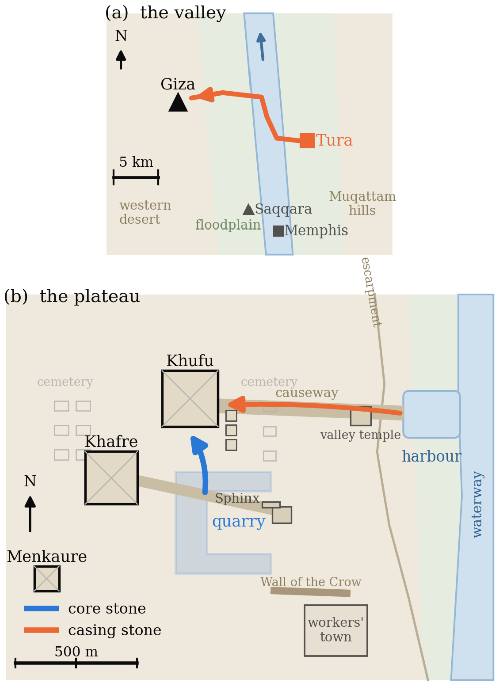
Figure 2.
The site as a chain of coupled stages, with the balanced crews at the baseline extraction rate of 0.10 cubic metres per man-day. Core stone runs along the top, casing stone from Tura along the bottom. The orange arc is the finding of Section 4: on nine working days in ten the lift had capacity to spare and was waiting for stone.
Figure 2.
The site as a chain of coupled stages, with the balanced crews at the baseline extraction rate of 0.10 cubic metres per man-day. Core stone runs along the top, casing stone from Tura along the bottom. The orange arc is the finding of Section 4: on nine working days in ten the lift had capacity to spare and was waiting for stone.
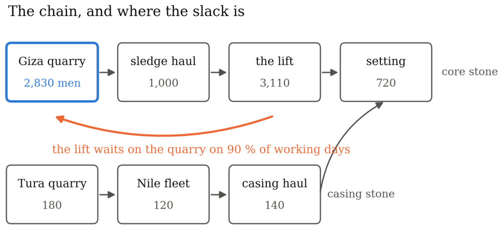
Figure 3.
Every twenty-seven-year build lies on one curve (blue). The dotted violet curve is the same constraint for a twenty-year build. Black points are simulated builds from Table 2; the violet square is de Haan’s 2009 levering study, placed at the extraction rate his own figures imply but never state. Above 6,000 quarrymen there is no working face to stand on, which truncates the curve at 0.047 cubic metres per man-day. The experimental rate of Burgos and Laroze, about 0.05, sits on the floor; 0.02, the lowest rate in Table 2, is refused.
Figure 3.
Every twenty-seven-year build lies on one curve (blue). The dotted violet curve is the same constraint for a twenty-year build. Black points are simulated builds from Table 2; the violet square is de Haan’s 2009 levering study, placed at the extraction rate his own figures imply but never state. Above 6,000 quarrymen there is no working face to stand on, which truncates the curve at 0.047 cubic metres per man-day. The experimental rate of Burgos and Laroze, about 0.05, sits on the floor; 0.02, the lowest rate in Table 2, is refused.
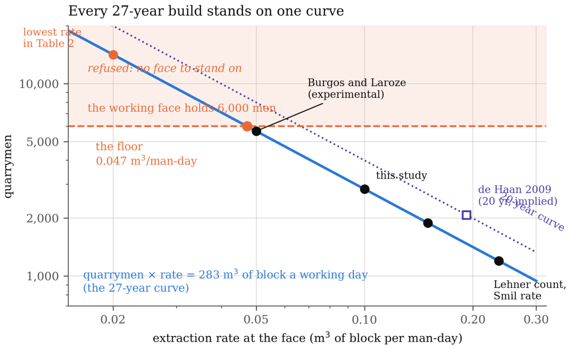
Figure 4.
The camp across the admissible band. The green segment, every stage other than the quarry, is nearly constant. The band as a whole runs from 7,511 to 13,720 men.
Figure 4.
The camp across the admissible band. The green segment, every stage other than the quarry, is nearly constant. The band as a whole runs from 7,511 to 13,720 men.
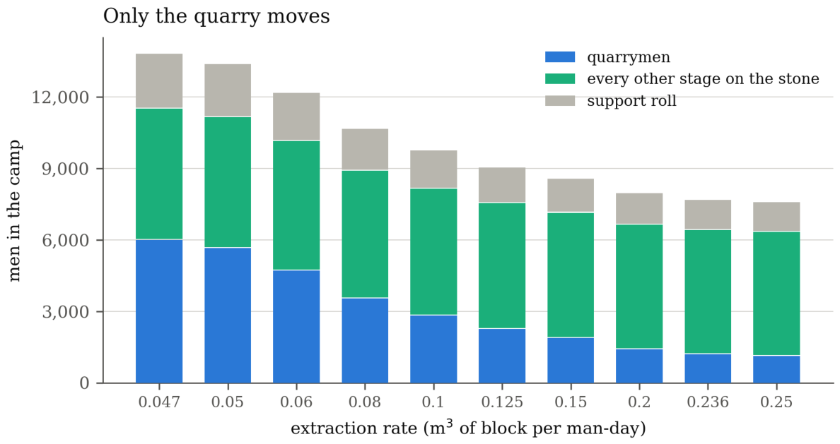
Figure 5.
What the site was waiting for, as a share of working days, under three lifting schemes on the same balanced site. The blue segment is the lift with capacity to spare. Only the straight ramp, whose two lanes cannot dispatch fast enough, spends a substantial share of the build limited by its own throughput.
Figure 5.
What the site was waiting for, as a share of working days, under three lifting schemes on the same balanced site. The blue segment is the lift with capacity to spare. Only the straight ramp, whose two lanes cannot dispatch fast enough, spends a substantial share of the build limited by its own throughput.
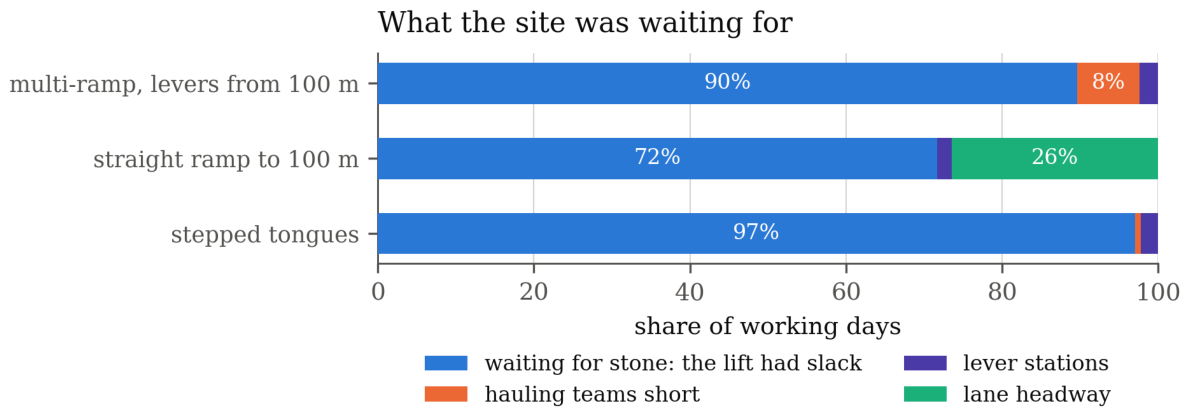
Figure 6.
Ramp grade against duration and against earthwork. The slope of the ramp is nearly free in time and expensive in earth.
Figure 6.
Ramp grade against duration and against earthwork. The slope of the ramp is nearly free in time and expensive in earth.
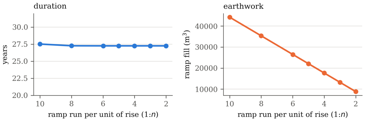
Figure 7.
The height at which levers take over from the ramp. Stopping the ramp lower saves earth and costs time. Above about 80 metres both curves flatten.
Figure 7.
The height at which levers take over from the ramp. Stopping the ramp lower saves earth and costs time. Above about 80 metres both curves flatten.
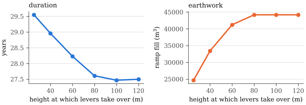
Figure 8.
The path of a stone, and where the lanes come from. (a) One face, drawn as the stair it is. A tongue of laid block climbs each riser, the tongues alternate in direction, and a stone goes up one, is turned at a post on the terrace, and goes up the next. This is the arrangement in the construction frames of [4]. The rise of a step and the depth of a terrace stand in the ratio of the seked, 5.5 to 7, as Section 5.2 sets out; the drawing exaggerates both against the width of the face. (b) One such route to a face gives four routes in all. A route is a pipeline and carries one lane unless its tongues are wide enough for two sledges abreast; it is lanes, not tongues, that the capacity calculation counts.
Figure 8.
The path of a stone, and where the lanes come from. (a) One face, drawn as the stair it is. A tongue of laid block climbs each riser, the tongues alternate in direction, and a stone goes up one, is turned at a post on the terrace, and goes up the next. This is the arrangement in the construction frames of [4]. The rise of a step and the depth of a terrace stand in the ratio of the seked, 5.5 to 7, as Section 5.2 sets out; the drawing exaggerates both against the width of the face. (b) One such route to a face gives four routes in all. A route is a pipeline and carries one lane unless its tongues are wide enough for two sledges abreast; it is lanes, not tongues, that the capacity calculation counts.
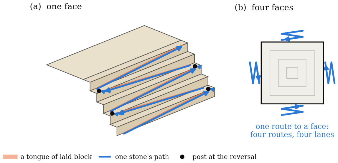
Figure 9.
Supply against demand, course by course. Left: the lanes a face can hold, for one face and for all four, against the 1.7 the quarry’s output requires. Right: the blocks in each course, which collapse by four orders of magnitude from base to summit. The two curves fall together, which is why the lift so rarely binds.
Figure 9.
Supply against demand, course by course. Left: the lanes a face can hold, for one face and for all four, against the 1.7 the quarry’s output requires. Right: the blocks in each course, which collapse by four orders of magnitude from base to summit. The two curves fall together, which is why the lift so rarely binds.
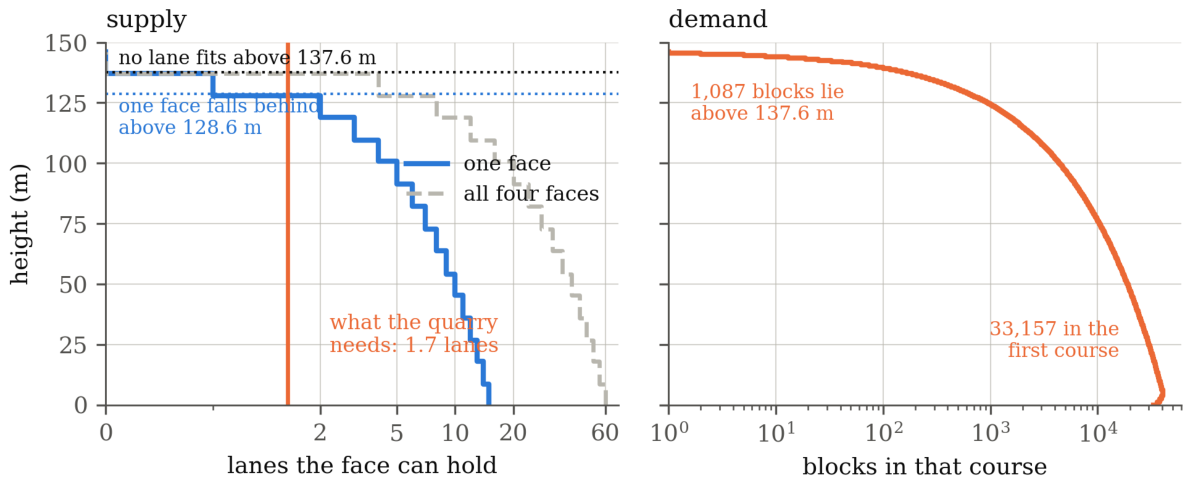
Figure 10.
The same build with the tongues confined to fewer faces. The schedule does not notice. The surplus block that has to be raised and then taken down again falls in proportion.
Figure 10.
The same build with the tongues confined to fewer faces. The schedule does not notice. The surplus block that has to be raised and then taken down again falls in proportion.
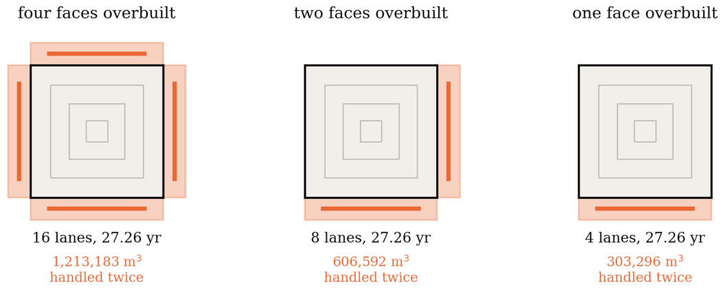
Figure 11.
Left: a stepped core inside the finished profile, with the shell added last; whether it descended from the summit or rose from the base is discussed at the end of this section. Right: the terrace width a given number of steps produces, against the one-lane width of 3.8 metres, with the volume of shell that remains to be added.
Figure 11.
Left: a stepped core inside the finished profile, with the shell added last; whether it descended from the summit or rose from the base is discussed at the end of this section. Right: the terrace width a given number of steps produces, against the one-lane width of 3.8 metres, with the volume of shell that remains to be added.
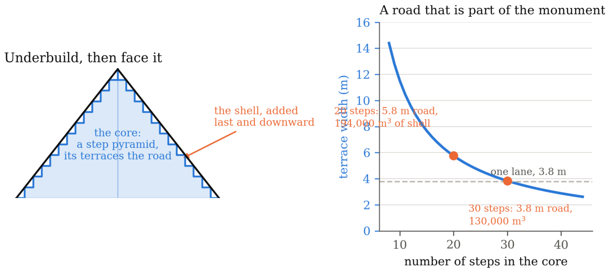
Figure 12.
Left: the only counterweight cycle that resets itself, because the ballast walks back up. Right: the share of the crew’s effort that becomes lift, for sledges on ramps of three grades and for a rope turned over a fixed wooden beam through three wrap angles. A half turn over a fixed beam is no better than the 1:10 ramp it would replace.
Figure 12.
Left: the only counterweight cycle that resets itself, because the ballast walks back up. Right: the share of the crew’s effort that becomes lift, for sledges on ramps of three grades and for a rope turned over a fixed wooden beam through three wrap angles. A half turn over a fixed beam is no better than the 1:10 ramp it would replace.
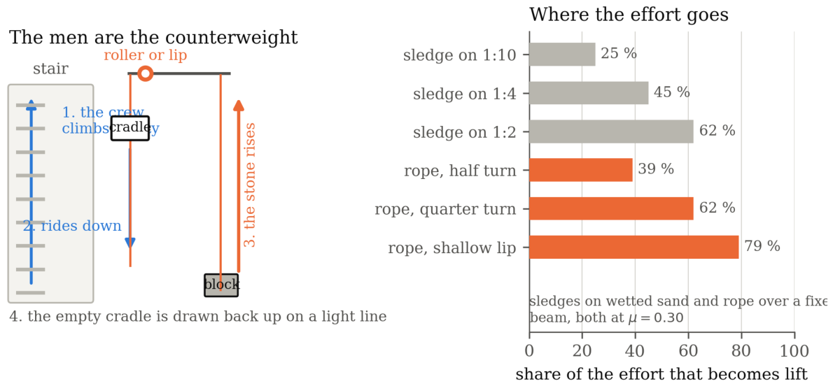
Figure 13.
Section of the monument in its own units, 440 cubits on 280, with the three heights at which the work runs out of room. The seked of five and a half palms fixes the setback at 5.5/7 of a cubit per cubit of rise, which is the number that governs Section 5.2 as well.
Figure 13.
Section of the monument in its own units, 440 cubits on 280, with the three heights at which the work runs out of room. The seked of five and a half palms fixes the setback at 5.5/7 of a cubit per cubit of rise, which is the number that governs Section 5.2 as well.
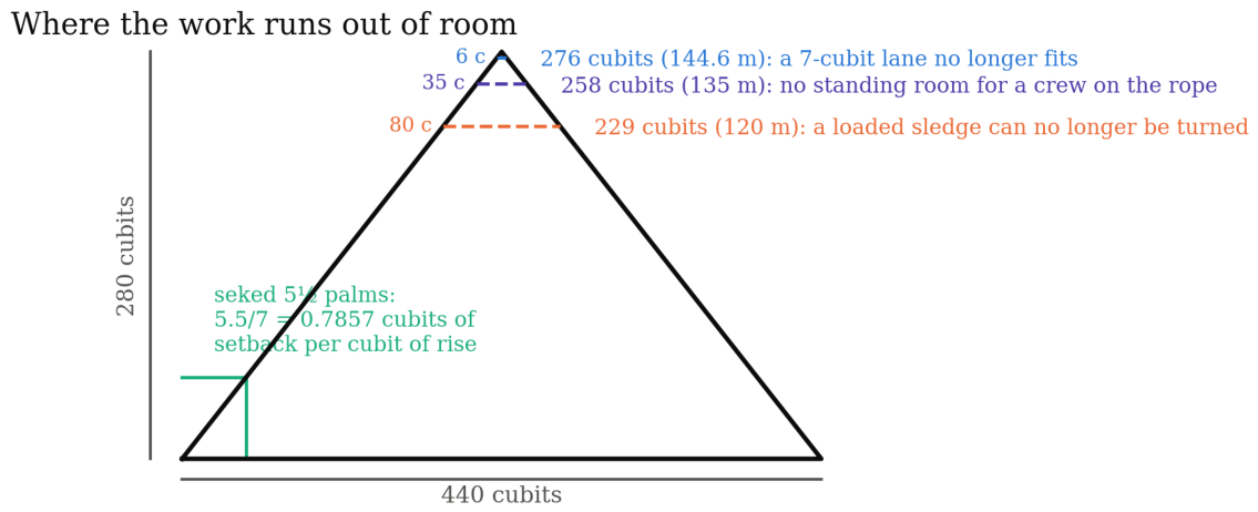
Figure 14.
Duration against the speed of a lever station. Between 25 and 30 minutes a block the scheme stops being able to finish, and adding crews does not rescue it: at 30 minutes the run stalls at course 204, six courses short of the apex. Sixty crews and four hundred and eighty crews give the same answer.
Figure 14.
Duration against the speed of a lever station. Between 25 and 30 minutes a block the scheme stops being able to finish, and adding crews does not rescue it: at 30 minutes the run stalls at course 204, six courses short of the apex. Sixty crews and four hundred and eighty crews give the same answer.
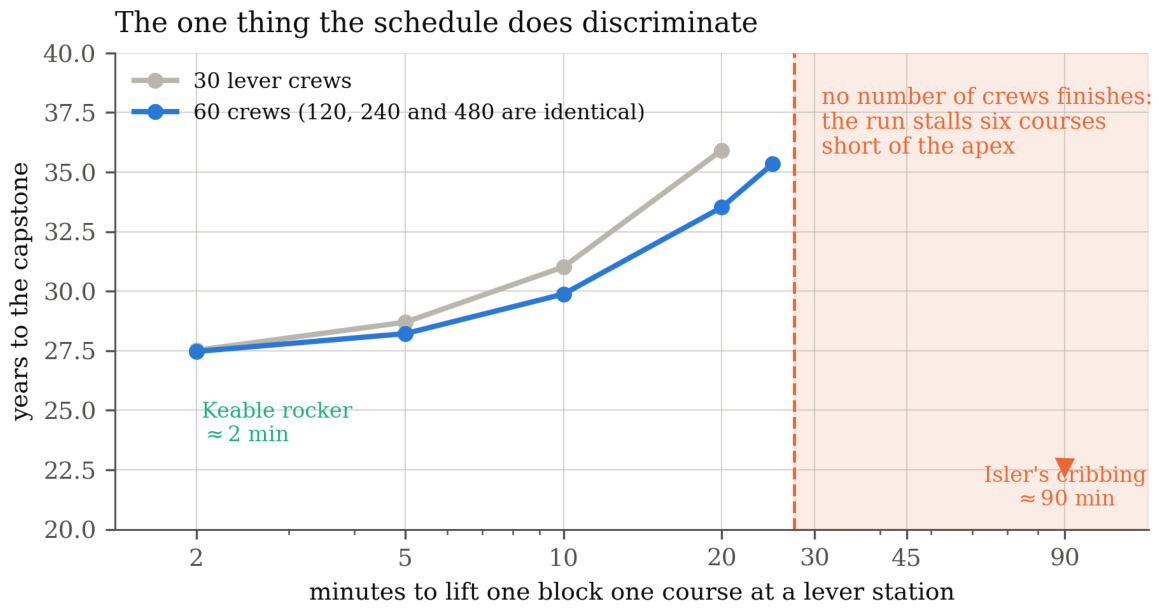
Figure 15.
The two topologies. A spiral leaves each face at the corner and turns through ninety degrees; a zigzag reverses on the same face through a hundred and eighty. A tongue whose sledge is shifted laterally at its head turns through nothing at all; a tongue whose sledge is sent back along the next one is a zigzag. Only the spiral and the zigzag need the manoeuvre discussed here.
Figure 15.
The two topologies. A spiral leaves each face at the corner and turns through ninety degrees; a zigzag reverses on the same face through a hundred and eighty. A tongue whose sledge is shifted laterally at its head turns through nothing at all; a tongue whose sledge is sent back along the next one is a zigzag. Only the spiral and the zigzag need the manoeuvre discussed here.
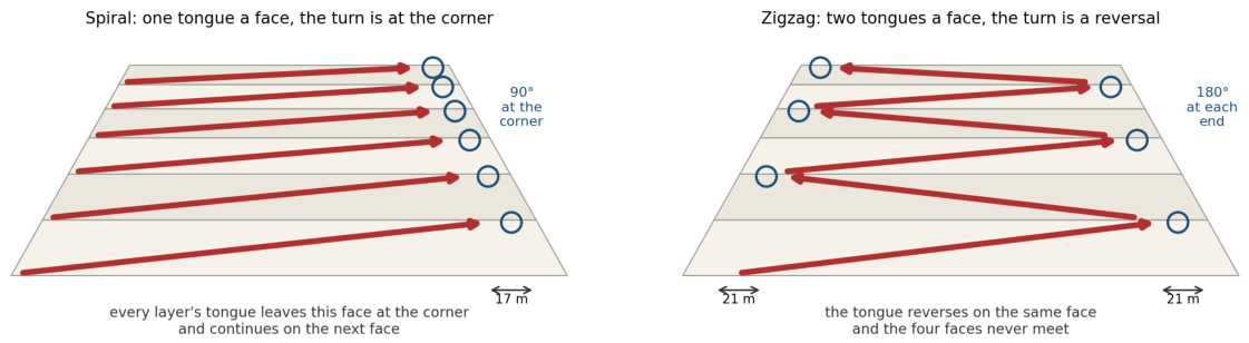
Figure 16.
Left: the length of one side against height, with the two geometric limits. Below about 120 metres a loaded sledge can be swung round a corner. Between there and 144.6 metres it cannot, but a lane still fits, and that band is half a per cent of the pyramid’s volume. Above 144.6 metres no lane fits and eight blocks remain. Right: the turn in plan, with the rope snubbed round a fixed post.
Figure 16.
Left: the length of one side against height, with the two geometric limits. Below about 120 metres a loaded sledge can be swung round a corner. Between there and 144.6 metres it cannot, but a lane still fits, and that band is half a per cent of the pyramid’s volume. Above 144.6 metres no lane fits and eight blocks remain. Right: the turn in plan, with the rope snubbed round a fixed post.
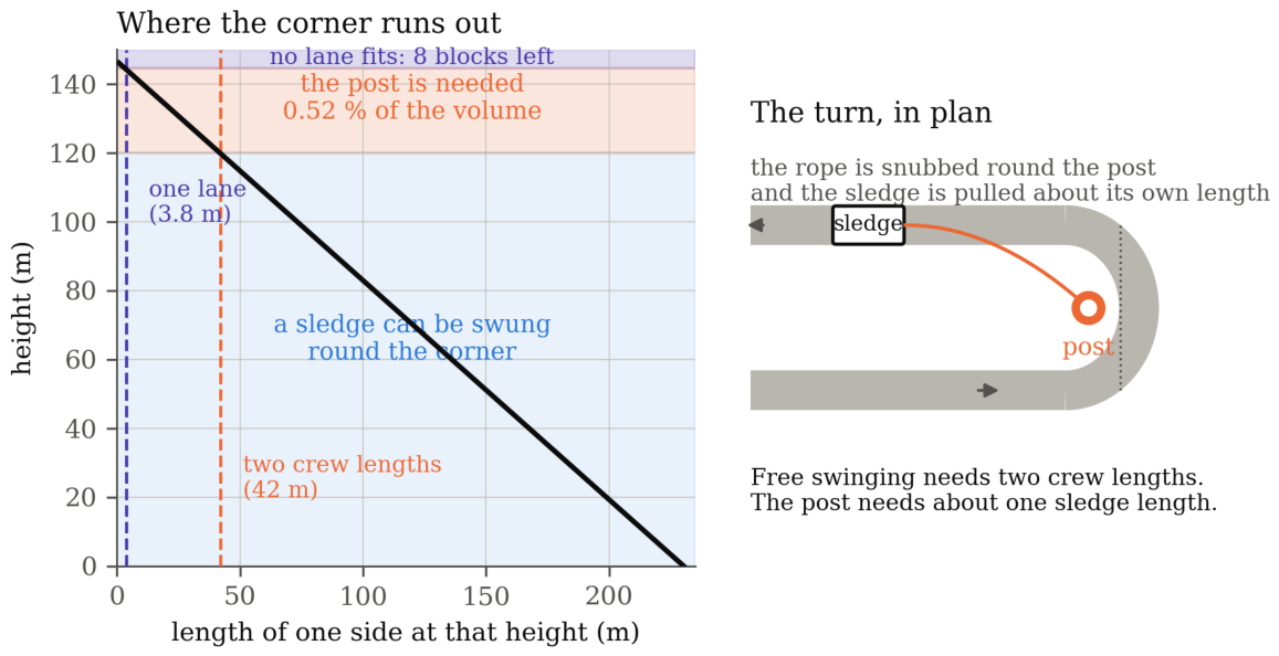
Figure 17.
The same comparison in three dimensions. A single straight ramp to 100 metres asks for more earth than the pyramid contains and about twice what the quarry could ever have yielded. Note also the assumption behind that figure: it prices the ramp as a prism with side slopes at one to one over its whole length, which is a modelling choice and not an observation.
Figure 17.
The same comparison in three dimensions. A single straight ramp to 100 metres asks for more earth than the pyramid contains and about twice what the quarry could ever have yielded. Note also the assumption behind that figure: it prices the ramp as a prism with side slopes at one to one over its whole length, which is a modelling choice and not an observation.
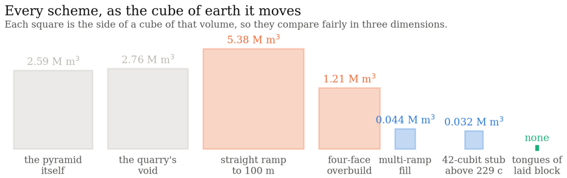
Figure 18.
Ramp fill raised and later removed, by scheme, against the 2.76 million cubic metres of the Khufu quarry’s void. A straight ramp to 100 metres requires nearly twice the quarry’s entire capacity in fill. Tongues of laid block require none.
Figure 18.
Ramp fill raised and later removed, by scheme, against the 2.76 million cubic metres of the Khufu quarry’s void. A straight ramp to 100 metres requires nearly twice the quarry’s entire capacity in fill. Tongues of laid block require none.
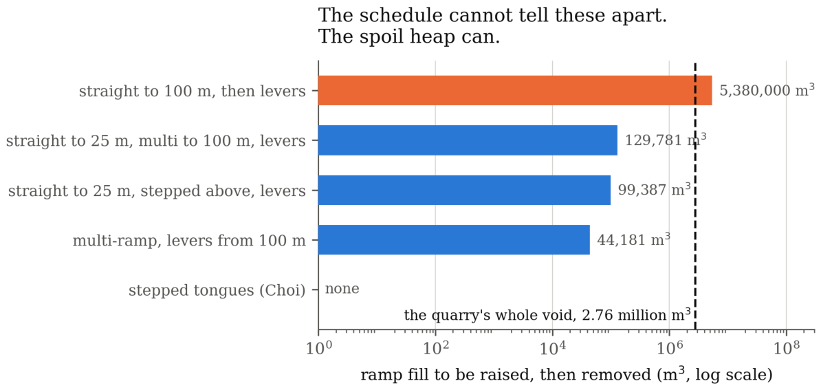

Table 1.
The curve is a relation; its constant is an assumption. A shorter build raises the required daily output, raises the extraction-rate floor set by the working face, and raises the quarry crew in proportion.
Table 1.
The curve is a relation; its constant is an assumption. A shorter build raises the required daily output, raises the extraction-rate floor set by the working face, and raises the quarry crew in proportion.
| build duration | of block a working day | the floor | quarrymen at 0.10 |
|---|---|---|---|
| 20 years | 389 | 0.065 | 3,891 |
| 23 years (Turin) | 338 | 0.056 | 3,384 |
| 27.5 years (our baseline) | 283 | 0.047 | 2,830 |
Table 2.
The rate table in fixed mode on a balanced site. Every admissible rate gives the same duration. Only the camp moves.
Table 2.
The rate table in fixed mode on a balanced site. Every admissible rate gives the same duration. Only the camp moves.
| extraction rate | quarrymen | years | peak on stone | camp |
|---|---|---|---|---|
| (/man-day) | required | |||
| 0.020 | 14,150 | refused: 6,000 places at the face | ||
| 0.030 | 9,434 | refused | ||
| 0.040 | 7,075 | refused | ||
| 0.047 | 6,022 | refused | ||
| 0.0472 (the floor) | 6,000 | 27.50 | 11,468 | 13,720 |
| 0.050 (Burgos and Laroze, experimental) | 5,660 | 27.52 | 11,110 | 13,290 |
| 0.060 | 4,717 | 27.52 | 10,107 | 12,086 |
| 0.080 | 3,538 | 27.52 | 8,853 | 10,582 |
| 0.100 | 2,830 | 27.52 | 8,100 | 9,678 |
| 0.125 | 2,264 | 27.52 | 7,498 | 8,956 |
| 0.150 | 1,887 | 27.51 | 7,098 | 8,476 |
| 0.200 | 1,415 | 27.52 | 6,595 | 7,872 |
| 0.236 (Lehner count, Smil rate) | 1,200 | 27.50 | 6,367 | 7,598 |
| 0.250 (Smil) | 1,132 | 27.52 | 6,294 | 7,511 |
Table 3.
The extraction-rate floor against the assumed number of places at the face, in fixed mode on the balanced site. Every admissible cell finishes in 27.52 years. A larger face admits a slower rate at the price of a larger camp; at 15,000 places a rate of 0.02 is admissible and costs a camp of 24,000. The paper’s 6,000 is three benches along the horseshoe’s perimeter, and it is a lower bound on the frontage rather than an estimate of it (Section 11).
Table 3.
The extraction-rate floor against the assumed number of places at the face, in fixed mode on the balanced site. Every admissible cell finishes in 27.52 years. A larger face admits a slower rate at the price of a larger camp; at 15,000 places a rate of 0.02 is admissible and costs a camp of 24,000. The paper’s 6,000 is three benches along the horseshoe’s perimeter, and it is a lower bound on the frontage rather than an estimate of it (Section 11).
| places at | floor | camp at an extraction rate of | ||||
|---|---|---|---|---|---|---|
| the face | (/man-day) | 0.02 | 0.03 | 0.04 | 0.05 | 0.10 |
| 4,000 | 0.071 | refused | refused | refused | refused | 9,678 |
| 6,000 | 0.047 | refused | refused | refused | 13,290 | 9,678 |
| 9,000 | 0.031 | refused | refused | 15,096 | 13,290 | 9,678 |
| 12,000 | 0.024 | refused | 18,107 | 15,096 | 13,290 | 9,678 |
| 15,000 | 0.019 | 24,126 | 18,107 | 15,096 | 13,290 | 9,678 |
Table 4.
Published proposals placed on the curve [5,7,23,25]. The extraction rate is the most consequential parameter in any of these models and it is usually invisible in them.
| source | duration | quarrymen | rate implied | stated? |
|---|---|---|---|---|
| assumed | (/man-day) | |||
| Burgos and Laroze 2020, experimental | not fixed | 5,660 would be needed | about 0.05 | rate measured |
| the Giza face, saturated | 27.5 yr | 6,000 | 0.047 | this paper |
| this study, baseline | 27.5 yr | 2,830 | 0.100 | chosen |
| de Haan 2009, maximum case | 20 yr | 2,805 | 0.142 | not stated |
| de Haan 2009, base case | 20 yr | 2,077 | 0.192 | not stated |
| Smil’s rate at Merer’s reign | 27.5 yr | 1,200 | 0.236 | rate stated |
| Scheuring 2025 | 20 yr | not modelled | undetermined | no |
Table 5.
Lifting schemes on the same balanced site at the same extraction rate. The four that hold the pace agree to within three months. Their earthworks differ by five orders of magnitude.
Table 5.
Lifting schemes on the same balanced site at the same extraction rate. The four that hold the pace agree to within three months. Their earthworks differ by five orders of magnitude.
| scheme | years | ramp fill () | note |
|---|---|---|---|
| multi-ramp, levers from 100 m | 27.52 | 44,181 | the baseline |
| straight to 25 m, multi above, levers | 27.52 | 129,781 | |
| stepped tongues of laid block | 27.26 | 0 | Choi [4] |
| straight to 25 m, stepped above, levers | 27.26 | 99,387 | |
| straight ramp to 100 m, levers above | 28.42 | 5,380,000 | headway-limited |
| levers from the ground, one minute a course | 27.90 | 0 | Crozat [3], Section 7 |
| levers from the ground, two minutes a course | 30.56 | 0 | |
| levers from the ground, five minutes a course | stalls at 127 m in forty years | ||
| spiral from 30 m, levers from 80 m | stalls at course 139, 111 m | ||
| multi-ramp to the top, no levers | stalls at course 206, 145 m | ||
| spiral to the top, no levers | stalls at course 139, 111 m | ||
Table 6.
The same build with the measured tongue widths of [4]. One route carries the lower half of the pyramid. A second route is needed above the King’s Chamber and a third is worth nothing. The ideal, never falling behind the quarry, is 9,044 days.
Table 6.
The same build with the measured tongue widths of [4]. One route carries the lower half of the pyramid. A second route is needed above the King’s Chamber and a third is worth nothing. The ideal, never falling behind the quarry, is 9,044 days.
| below 43 m (2 lanes a route) | above 43 m (1 lane a route) | lifting days |
|---|---|---|
| one route | one route | 11,892 |
| one route | two routes | 9,044 |
| one route | three routes | 9,044 |
| two routes | two routes | 9,044 |
Table 7.
The stepped tongues with the lane count reduced, on the same balanced site at per man-day. Four lanes carry the entire build with no day lost to headway. Everything beyond that is infrastructure the quarry cannot feed.
Table 7.
The stepped tongues with the lane count reduced, on the same balanced site at per man-day. Four lanes carry the entire build with no day lost to headway. Everything beyond that is infrastructure the quarry cannot feed.
| lanes | equivalent to | years | days limited by lane headway |
|---|---|---|---|
| 16 | four routes on each of four faces | 27.26 | 0 |
| 8 | four routes on each of two faces | 27.26 | 0 |
| 4 | one route to each of four faces | 27.26 | 0 |
| 3 | three routes in all | 27.26 | 108 |
| 2 | two routes in all | 28.36 | 2,517 |
| 1 | a single route | does not finish; stalls at 80 m | |
Table 8.
A stepped core in cubits. Only a rise that is a multiple of seven cubits gives a terrace in whole cubits, and of those only twenty steps of fourteen cubits leaves a road wide enough to drive on: eleven cubits exactly.
Table 8.
A stepped core in cubits. Only a rise that is a multiple of seven cubits gives a terrace in whole cubits, and of those only twenty steps of fourteen cubits leaves a road wide enough to drive on: eleven cubits exactly.
| steps | step rise | terrace | terrace |
|---|---|---|---|
| (cubits) | (cubits) | (m) | |
| 10 | 28 | 22 | 11.5 |
| 20 | 14 | 11 | 5.8 |
| 28 | 10 | 7.86 | 4.1 |
| 40 | 7 | 5.5 | 2.9 |
Table 9.
What each scheme costs to have a road. Only the stepped core moves nothing that the finished pyramid does not contain.
Table 9.
What each scheme costs to have a road. Only the stepped core moves nothing that the finished pyramid does not contain.
| scheme | material moved for the road | handled |
|---|---|---|
| overbuild and carve, four faces (top side 80 m) | 1,213, | twice |
| overbuild and carve, one face (Section 5.1) | about 302, | twice |
| multi-ramp of imported fill | 44, | twice |
| stepped core, 20 steps | 194, of shell | once |
| stepped core, 30 steps | 130, of shell | once |
Table 10.
Overbuilding costs what it costs; the question is how much of the height needs it. Confined to the courses where area is actually scarce, the surplus falls by a factor of nearly forty. On one or two faces rather than four it falls again in proportion.
Table 10.
Overbuilding costs what it costs; the question is how much of the height needs it. Confined to the courses where area is actually scarce, the surplus falls by a factor of nearly forty. On one or two faces rather than four it falls again in proportion.
| working profile | surplus to carve () | |
|---|---|---|
| full-height frustum, 100 m top side | 1,614,213 | |
| full-height frustum, 80 m top side | 1,213,183 | as drawn in [4] |
| full-height frustum, 40 m top side | 528,405 | |
| 50 m stub above 110 m | 50,353 | |
| 42 m stub above 120 m | 31,759 | two crew lengths |
| 36 m stub above 125 m | 19,436 | |
| 30 m stub above 130 m | 11,053 | a lane, no turning |
Table 11.
Working days to place everything above 100 metres, against the 9,040 working days of the whole build. Hoisting assumes a haul at 0.1 m/s. The figure that matters is not the speed of the mechanism but how often the block must be re-gripped.
Table 11.
Working days to place everything above 100 metres, against the 9,040 working days of the whole build. Hoisting assumes a haul at 0.1 m/s. The figure that matters is not the speed of the mechanism but how often the block must be re-gripped.
| scheme | assumption | working days |
|---|---|---|
| levers, one course a grip | 1 minute a course | 142 |
| 2 minutes | 284 | |
| 5 minutes | 709 | |
| 10 minutes | 1,419 | |
| hoist, one grip a span | 5 m span, 4 min a grip | 82 |
| 5 m span, 8 min a grip | 151 | |
| 10 m span, 4 min a grip | 52 | |
| 10 m span, 8 min a grip | 92 | |
| 25 m span, 4 min a grip | 36 | |
| the whole rise, 8 min | 50 |
Table 12.
The limits near the apex. All four are statements about area, and they bind within twenty-five metres of one another.
Table 12.
The limits near the apex. All four are statements about area, and they bind within twenty-five metres of one another.
| what runs out | height | what it is |
|---|---|---|
| room to turn a loaded sledge | 124.5 m | two crew lengths (34.8 m) of side |
| standing room for a crew hauling up the face | about 135 m | 18 m of run, side 18.1 m |
| room for a single 3.8 m lane | 144.6 m | the lane will not fit |
| anything left to lift | above 144.6 m | three courses, eight blocks |
Table 13.
What one 70 tonne beam costs in counterweight. The fixed-beam figure is the capstan law for a half turn at . The descending-passage figure is at , the passage’s own grade. A true bearing is therefore not a detail of the proposal, it is the proposal.
Table 13.
What one 70 tonne beam costs in counterweight. The fixed-beam figure is the capstan law for a half turn at . The descending-passage figure is at , the passage’s own grade. A true bearing is therefore not a detail of the proposal, it is the proposal.
| arrangement | fraction passed | counterweight | in blocks |
|---|---|---|---|
| vertical, true bearing | 1.00 | 70 t | 28 |
| vertical, rope over a fixed beam | 0.39 | 180 t | 72 |
| sliding down the descending passage | 0.18 | 394 t | 158 |
Table 14.
Levers from the ground, no ramp, on the balanced site at per man-day. Lever crews 240 to 1,920 give identical results; the column shown is for 240. Ramp fill is zero in every row.
Table 14.
Levers from the ground, no ramp, on the balanced site at per man-day. Lever crews 240 to 1,920 give identical results; the column shown is for 240. Ramp fill is zero in every row.
| minutes a block a course | years | height reached in forty years |
|---|---|---|
| 1 | 27.90 | |
| 2 | 30.56 | |
| 5 | 127 m | |
| 10 | 91 m | |
| 20 | 68 m | |
| 30 | 58 m |
Disclaimer/Publisher’s Note: The statements, opinions and data contained in all publications are solely those of the individual author(s) and contributor(s) and not of MDPI and/or the editor(s). MDPI and/or the editor(s) disclaim responsibility for any injury to people or property resulting from any ideas, methods, instructions or products referred to in the content. |
© 2026 by the authors. Licensee MDPI, Basel, Switzerland. This article is an open access article distributed under the terms and conditions of the Creative Commons Attribution (CC BY) license.
Copyright: This open access article is published under a Creative Commons CC BY 4.0 license, which permit the free download, distribution, and reuse, provided that the author and preprint are cited in any reuse.