

Submitted:
13 September 2026
Posted:
15 September 2026
You are already at the latest version
Abstract
Common middleware topics and message types do not ensure that control commands have the same meaning across robotic platforms. We audit version-pinned source code, configurations and specifications of Collaborative Robotics Toolkit (CRTK) interfaces in surgical robotics, identifying differences in Cartesian reference frames, physical units, state preconditions and stop behaviour. We derive task-space error bounds, including the exact maximum positional error of a frame mismatch over a command ball. Frame and uniform-unit mismatches can remain invisible when command and feedback share the same binding; identifying them requires an independent spatial relation or dimensional anchor. We release crtk-conformance, a black-box prototype that compares observable bindings with a client’s declared expectations and returns undetermined when evidence is insufficient. Against a configurable reference node, spatial error intervals contained truth in 240 of 240 replicated runs under Gaussian noise. Anchored scale estimates recovered injected scales from 0.1 to 10; one false divergence occurred at the fixed 1mm boundary. Liveness intervals contained the injected timeout in all 23 formed estimates, 22 conditional on observed run-maximum latency allowances. A heuristic source age interval contained event-log truth in 98 of 150 windows, with failures at both ends; rate conformance is therefore not decided. Runs against two released Surgical Robotics Challenge interfaces on AMBF corroborate topic inventory and state behaviour while leaving frame, unit and rate conformance undetermined. These results support an artifact audit and identifiability study with prototype verification, not hardware certification. We recommend explicit, discoverable frame, unit and timing contracts.
Keywords:
surgical robotics
; CRTK
; ROS
; interface conformance
; semantic interoperability
; coordinate frames
; conformance testing
1. Introduction
Surgical robotics research increasingly develops and pre-validates control algorithms in simulation before executing them on hardware. The da Vinci Research Kit (dVRK) [1,2], the Raven-II [3] and dynamic simulators such as the Asynchronous Multi-Body Framework (AMBF) [4] form a shared infrastructure for this work; a decade of dVRK research alone spans forty research centres in more than ten countries [5]. Portability of control code between these systems is therefore not a convenience but a load-bearing assumption of the field’s methodology: a policy learned in simulation [6,7,8] is only useful if the commands it emits mean the same thing on the robot.
The Collaborative Robotics Toolkit (CRTK) [9] addresses this by standardising a Robot Operating System (ROS) [10] interface: common topic names such as measured_cp and servo_cp, common message types, and a common vocabulary of operating states. A developer who sees the same topics with the same types on two platforms reasonably expects a control script to have the same effect on both.
This expectation is where the risk lies. A geometry_msgs/PoseStamped message can be structurally valid and semantically wrong: the position it carries may be interpreted relative to a different origin, in different units, or under a different rule about when a command is executed at all. In surgical robotics the failure mode is not a crash but a plausible-looking wrong motion. The canonical precedent is not from robotics: the Mars Climate Orbiter was lost because one component produced thruster impulse data in pound-force seconds while the component consuming it expected newton seconds, across an interface whose structure was entirely valid [11]. We therefore treat CRTK as an interface contract whose practical value depends on shared interpretation, and we study the gap between what a message contains and what the receiving platform understands it to contain.
This paper makes five contributions, each scoped to what its evidence supports. (1) We state the distinction between structural and semantic conformance as definitions on interface contracts, in a client-relative form that the released tool evaluates, and name three semantic binding classes: spatial, dimensional and temporal (Section 3). The distinction itself is not new—syntactic and semantic interoperability have been separated for decades [12]—and we claim no novelty for it; what is new is its application to CRTK with source-grounded evidence. (2) From released source code, configuration files and specification text—each cited by repository, version or commit, file and line—we document one divergence in each class across CRTK-related implementations, with the Raven-II CRTK adapter as corroborating artifact evidence (Section 4). (3) We derive a closed-form error model that propagates each divergence into task-space error, separating the cases that matter in practice: absolute versus incremental commands, divergences that a client can and cannot see through its own feedback, and threshold versus continuous temporal effects (Section 5). (4) We release crtk-conformance 0.1.4, a black-box test suite that discovers each binding through the public ROS interface, where the interface exposes it, and decides conformance only against an expectation the client declares and only on the channels it observed, together with crtk-mock, a configurable reference node with injectable divergences (Section 6); we verify the suite against the mock, including the coverage of its spatial intervals and the soundness of its state-precondition and liveness verdicts against the injected policies, and we score its rate diagnostic—which the tool reports without deciding, for the reason given in Section 6—against the mock’s own event record; we then run the suite against the released Surgical Robotics Challenge software, versions 1.0.0 and 2.0.0, executing on AMBF (Section 7). (5) We propose four concrete changes to the CRTK specification (Section 9).
Three layers of evidence appear in the paper and are kept visually distinct. [P] marks a statement read from a released artifact. [M-ref] marks a measurement against crtk-mock, a reference node we wrote, which can verify the tool’s implementation but says nothing about any platform. [M-live] marks a measurement against a released implementation actually executed: the SRC v1.0.0 and v2.0.0 CRTK interfaces running on the AMBF simulator in a pinned container. [A] marks an assumption the tool makes and records in its report rather than a measurement. No measurement was taken on a physical dVRK or Raven-II, and none on the SRC beyond the two releases and the configuration stated in Section 7; every error magnitude attributed to the dVRK is a model prediction from a released configuration value.
2. Background and Related Work
- Open platforms and their control rates.
The dVRK exposes decommissioned da Vinci manipulators through FPGA-based controllers and an open control stack; its 2014 description reports servo control at 1 kHz over IEEE-1394 and an FPGA watchdog with timeout periods from 1 to 340 ms that “trips and disables all power amplifiers” when the controller is not refreshed by the control PC [1]. Its software architecture separates I/O, low-level PID control, high-level arm logic and a ROS bridge [2]. The Raven-II runs a 1000 Hz real-time servo layer beneath a ROS node [3]. AMBF is a real-time dynamic simulator whose bodies exchange state and command messages over ROS at 1 kHz [4]; the Surgical Robotics Challenge (SRC) builds a dVRK-like simulated environment on it [13], and AMBF-RL adds reinforcement-learning environments [8]. Other dVRK-compatible simulators express the tool pose relative to the remote centre of motion (RCM) and note explicitly that “people frequently change the dVRK robot base frame relative to the virtual world frame” [7], and policies learned in simulation have been transferred to the dVRK with the robot “running at 50 Hz” [6]. Practical constraints of the physical dVRK—a tip-pose discrepancy of up to mm and mm of end-effector error per degree of potentiometer offset—are documented by Cui et al. [14].
- CRTK.
CRTK defines a common application programming interface for the Raven-II and the dVRK, extended to simulated and industrial robots [9]. Its documentation specifies topic names built from a space (joint or Cartesian), a type (position, velocity, effort) and a level (servo, interpolate, move), payload types drawn from standard ROS messages, and a four-state operating-state model [15,16]. Three properties of the specification text matter for this paper and are documented in Section 4: the specification requires the measurement and setpoint topics to name their reference frame in header.frame_id but does not make that name resolvable to a transform, defines the local/ frame only by the dVRK example, and gives the servo_cp command no payload specification at all; physical units are not mentioned; and the timing of servo commands is characterised only as “periodically at a rate close to the low-level rate”.
- Interoperability levels, unit and frame checkers, and ROS verification.
The separation of structural from semantic interoperability is an old one: the Levels of Conceptual Interoperability Model places syntactic interoperability (a common structure) below semantic interoperability (a common meaning of the exchanged content) [12], and our terms map onto those levels. Interoperability efforts adjacent to CRTK, such as ROS-IGTL-Bridge for image-guided therapy [17] and the migration of surgical tooling to ROS 2, standardise transport and message structure, not the semantics of the values carried. Two lines of work detect the same classes of error we study, but from the source code. Phriky-Units infers physical units in ROS C++ programs from the message types they use and reports dimensional inconsistencies without annotations, finding inconsistencies in 11 % of 213 open-source systems [18]; PhysFrame infers frame types for ROS variables and transforms and type-checks them against ROS conventions, finding 190 inconsistencies in 180 projects [19]. Both are static analyses of one program’s source; they detect a unit or frame error inside that program. They cannot see the divergence studied here, which lies between two programs that are each internally consistent: the SRC v1.0.0 interface is dimensionally consistent with itself, and a client written for metres is consistent with itself. Frame conventions for mobile platforms are fixed by REP-105 [20], which names the frames and their semantic meaning; nothing equivalent exists for the arm-base and RCM frames of a surgical manipulator, and CRTK does not import it. Static and runtime verification frameworks for ROS—HAROS, which analyses repositories and computation graphs for quality and architectural properties [21], and ROSMonitoring, which checks runtime traces against user-supplied properties by instrumenting the graph [22]—require the source, a model, or a formal property; they do not supply the property that a pose is in a particular frame or unit. ROS 2 quality-of-service policies provide a declarable temporal contract at the transport level: a deadline states “the expected maximum amount of time between subsequent messages being published to a topic” and liveliness with a lease duration lets the middleware detect a publisher that has stopped [23]. These declare and detect the loss of a message stream; they say nothing about what the receiving controller does with the setpoint when the stream stops, which is the temporal binding studied here, and the ROS 1 implementations examined do not use them.
crtk-conformance differs from all of these in what it needs and what it detects. It needs no source code, annotation, model or instrumentation of the implementation under test: it sees the ROS graph, the messages it receives and the commands it publishes, exactly what a porting researcher sees. It detects whether the bindings discovered through that interface agree with the bindings a client declares it was written for, and it reports the cases in which the interface does not expose enough to decide. Its novelty is therefore not the structural/semantic distinction, nor any of its mathematics, which is textbook, but the combination: a CRTK-specific, source-grounded audit of released implementations; the propagation of each divergence into task-space error with the identifiability limits made explicit; a black-box discovery and client-relative conformance probe; a reproducible tool with a reference node; and its execution against released CRTK-related software. Human tolerance to communication delay in telesurgery has been measured at about 100 ms [24], a different quantity from the command-rate policies studied here. Conformance testing in the formal sense checks an implementation against a specification, classically through labelled transition systems and input–output conformance [25]; we borrow the vocabulary but not the machinery, since CRTK has no formal behavioural model against which an implementation could be checked.
3. Structural Versus Semantic Conformance
We define an interface contract as a pair . The structural signature is the set of topic names with their message types and field layouts. The semantic binding assigns to each field of each message the information needed to interpret its value: the reference frame in which a pose is expressed, the physical unit of each component, and the temporal and state precondition under which a command message is honoured. For a client program C let be the part of the signature that C uses. Two implementations A and B are structurally compatible for C if and only if with matching message types on every element of ; they are structurally conformant outright if and only if . The client-relative form is the one this paper uses, because implementations legitimately expose different optional surfaces (the SRC interface of Section 4, for instance, exposes no local/ topics): it is what allows two implementations offering the same Cartesian topics to be interchangeable structurally while diverging in . They are semantically conformant with respect to a binding class if and only if and agree on every field in . Structural compatibility for C is necessary for C to run unchanged on both implementations; it is not sufficient for C to have the same effect, because the effect depends on .
We address three binding classes. The spatial class binds every Cartesian pose to a reference frame. The dimensional class binds every numeric component to a physical unit. The temporal class binds every command topic to the state precondition under which it is executed, to the rate at which it is expected, and to the behaviour when the command stream stops. These classes are not exhaustive: contact dynamics, force semantics, joint-limit behaviour and message-timestamp semantics are further classes that a complete contract would have to bind, and they are outside the scope of this paper.
The relation is what the released tool evaluates, in its client-relative form: the client declares the binding it was authored against (Section 6), the probes discover of the implementation under test through the interface, and the outcome states whether the two agree on the declared fields to within the client’s tolerance. Without a declared there is nothing to compare against and the tool reports without a verdict. These are definitions and a notation, not a formal semantic theory; we do not claim more.
Figure 1 illustrates the distinction on the two topics at the centre of this paper. The same PoseStamped on servo_cp is structurally identical on the dVRK and SRC implementations examined; the Raven-II adapter examined predates the specification’s 2022 change of payload and carries a TransformStamped, so for an unchanged PoseStamped client it is not a structural match and enters this paper as corroborating evidence about semantics, not as a third interchangeable implementation. The specification requires the measured pose to carry the name of its reference frame, but binds that name to no transform, gives servo_cp no payload specification, and binds neither unit nor precondition at all; so the binding is supplied, per implementation, by code and configuration that the client never sees.
4. Three Semantic Divergences in Released Artifacts
Every statement in this section is read from a released artifact and cited by repository, tag or commit, file and line; the class tag [P] marks it as a primary-artifact claim. Each divergence is presented in four parts: the divergence, the primary evidence, its detectability through the CRTK interface, and its consequence, with a forward reference to the error model. Table 1 summarises the evidence and Figure 2 illustrates the three classes. All repositories were cloned on 2 September 2026.
4.1. D1 — Spatial: Binding of the Unqualified Cartesian Topics
The divergence. The released implementations bind the unqualified topics measured_cp and servo_cp to different reference frames, supply the binding in different ways, and expose it to different degrees. The dVRK binds them to a configurable base_frame, identity by default, and publishes both the bound pose and the raw arm-base pose (local/). The SRC binds them to the fixed arm-base frame and publishes no local/ topic. The Raven-II CRTK adapter binds them to a compile-time rotation of the robot base that differs between its two arms, publishes no local/ topic and leaves the frame_id field empty. The specification requires the frame to be named, documents the dVRK convention by example, and leaves everything else to the implementation: it makes neither the transform behind the name discoverable nor the dVRK convention normative for other platforms, and it specifies nothing about the frame in which a servo_cp command is interpreted.
Primary evidence. Three statements about the specification must be kept apart. First, what it requires: measured_cp specifies “string header.frame_id: reference frame [required]” ([15], api-robot-motion.rst, line 368), repeats the requirement for measured_cv, measured_cf and setpoint_cp (lines 392, 421, 543), and asks measured_js to carry the same string (lines 332–333) [P]. Second, what it documents by example: “For the dVRK, /PSM1/measured_cp is defined with respect to the camera coordinate system. If a user needs access to the cartesian position with respect to the local coordinate system of the PSM, i.e. it’s RCM (remote center of motion), they can use the topic /PSM1/local/measured_cp” (lines 229–233), and, at the same commit, the client documentation explains that measured_cp “reports the pose in the frame defined by base_frame” while local/measured_cp “reports the pose without applying any existing base_frame, i.e. in the raw device frame” ([15], client-python.rst, lines 445–458) [P]. Third, what it leaves open: the entire specification of servo_cp is the phrase “Set position cartesian setpoint (low-level)” with no payload specification (lines 711–714); for the joint-space servo commands the text states that “stamp, frame_id and name are not used by the command so they could be left empty” (lines 630, 645); and local/ is defined nowhere except by the dVRK example [P]. The sentence “Instead of using the ROS frame_id to define the reference frame, we used namespaces to define the reference frame” (lines 285–288) belongs to a bullet about the spatial and body frames of wrench and twist commands; it does not govern pose frames.
The dVRK implements the documented convention. In the released arm component the reference frame of both measured_cp and local/measured_cp defaults to <arm>_base (mtsIntuitiveResearchKitArm.cpp, lines 259 and 269), the base frame defaults to the identity (line 255), the unqualified measured pose is the product of the base frame and the local pose (line 976), and the goal of an unqualified servo_cp is pre-multiplied by the inverse base frame before inverse kinematics (line 1602); when a base frame is configured, the reference-frame string of the unqualified topics becomes the configured name while local/ keeps <arm>_base (arm_proxy.cpp, lines 457–459; arm component, lines 2286–2287) ([26], release 2.5.0) [P]. The dVRK documentation states the same as measured_cp =base_frame DH tooltip-offset and local/measured_cp= DH tooltip-offset ([27], frames/arm.rst, lines 74–75). The base frame is a deployment parameter. In the released Johns Hopkins University configuration repository, nineteen base_frame blocks across 38 system files reference the frame ECM; the PSM2 block of system-MTMR-PSM2-Teleop.json gives a translation of and a rotation matrix whose rows are , and ([28], lines 22–28) [P]; that matrix is a rotation of -150 about the x axis [D]. We quote it as one configured value, not as a property of the dVRK.
The SRC departs from the documented convention rather than from spec silence. Its CRTK interface script publishes a single measured_cp whose frame_id is <psm>/baselink, publishes a separate topic T_b_w with frame_id world, and defines no local/ topics; this holds at v1.0.0 (launch_crtk_interface.py, lines 138–140), v2.0.0 (lines 109–111) and the current default branch (lines 114–116) [13] [P]. Its servo_cp goal is passed directly to the arm’s inverse kinematics and its measured_cp is the arm’s forward kinematics, with no base transform applied (psm_arm.py v1.0.0, lines 160–166 and 203–206) [P]. Both are therefore expressed in the DH base of the arm, whose origin is the intersection of the yaw, pitch and insertion axes—the remote centre of motion, the same origin the dVRK’s local/ frame uses ([26], PSM.json, line 32); the dVRK documentation locates the physical RCM “near the large black band on the cannulas” ([27], mount/psm.rst, lines 25–26).
The Raven-II CRTK adapter corroborates the pattern from a third code base. Su et al. describe it as reformulating servo_cr “by a change in units and a spatial transformation of the reference coordinates from the CRTK frame to the Raven-II base frame” [9]. In the released source the transformation is a fixed rotation per arm with zero translation, and a different matrix for the second arm (crtk_motion_api.cpp, lines 41–46, installed as the base frame at lines 83–91); measured_cp is the base transform applied to the robot pose (update_device_state.cpp, lines 224–227) and commands are pre-multiplied by its inverse (lines 320 and 377); the unit change is an internal conversion between the robot’s micron representation and metres on the interface (defines.h, line 429; update_device_state.cpp, lines 220, 320, 377), so the interface itself is in metres; the publisher of measured_cp never sets header.frame_id (local_io.cpp, lines 995–1026); no local/ topic exists; and the payload is the pre-2022 TransformStamped rather than PoseStamped (lines 568–590, 647–655) [29] [P]. Three released implementations thus bind the same topic to three differently supplied frames, of which only the dVRK exposes the binding through the interface.
Detectability. When an implementation exposes both measured_cp and local/measured_cp, the binding transform is observable as their quotient. When it exposes only one, the binding cannot be verified through the interface: the frame_id string, where present, names a frame (ECM, PSM1_base, psm1/baselink) but is tied to no discoverable transform, and T_b_w, where present, relates the arm base to the world, not the unqualified frame to the arm base. This asymmetry is exploited, and its limit respected, by the probe of Section 6, which returns undetermined rather than a verdict when local/ is absent.
Consequence. A client authored against one binding and run against another has every absolute command displaced by the transform between them; the error is analysed in Section 5.1, where the released JHU value serves as the illustrative magnitude. Whether a given client is affected is relative to the binding it was authored against, which is why the tool of Section 6 asks the client to declare it.
4.2. D2 — Dimensional: Cartesian Units of the SRC v1.0.0 Interface
The divergence. The released SRC v1.0.0 interface exchanges Cartesian quantities in a unit of m; v2.0.0 exchanges metres.
Primary evidence. The v1.0.0 kinematic model declares L_rcc = 4.389 # From dVRK documentation x 10 and L_tool = 4.16 # From dVRK documentation x 10 (kinematics/psmFK.py, lines 70–71); a comment in the same release equates 0.05 Simulation units with 5 mm (psm_arm.py, line 106) [13] [P]. The dVRK kinematic file declares the corresponding insertion offset as in metres ([26], PSM.json, line 32), and v2.0.0 of SRC declares with a joint limit annotated 0.24, // 240 mm (psm_400006.json, lines 32 and 34) and introduces a unit-conversion layer with linear_factor = 1.0 (units_conversion.py, line 6) [P]. The v2.0.0 change log lists, under Bug fixes: “Rescaled simulation assets to SI units and tune the physical properties of the objects. (In version 1.0.0, the assets were scaled by 10)” (CHANGELOG.md, line 29) [P]. ROS’s REP-103 states “We have chosen to standardize on SI units” with the metre as the unit of length [30] [P]; the CRTK specification text contains no occurrence of the words unit, metre, radian or SI [15] [P].
We describe v1.0.0 as a factor-of-ten dimensional divergence from the REP-103 convention that the project itself later classified as a bug.
Detectability. Section 5.2 shows, by a dimensional-analysis argument, that a uniform unit scale cannot be identified from ratios of like-dimensioned interface quantities. It is detectable only against a unit anchor: a length whose physical value is known independently of the interface.
Consequence. A client authored for metres and run against v1.0.0 executes one tenth of every commanded displacement, and—because it reads its feedback through the same interface—reports success (Section 5.2).
4.3. D3 — Temporal: State Precondition, Rate Policy and Stop Behaviour of servo_cp
The divergence. The dVRK adopts the specification’s optional operating-state machine: it executes servo_cp only in an enabled, homed state, and the examined arm component retains the last accepted goal, no command-age timeout having been identified in that layer. The SRC interface does not adopt it: it has no operating state and executes servo_cp in the subscriber callback whenever a message arrives, after which the command reaches the simulator through a client republisher in which the latest command wins at 120 Hz. The specification makes the state machine optional and binds neither the rate policy nor the stop behaviour.
Primary evidence. CRTK states that “Users are expected to send commands periodically at a rate close to the low-level rate. These commands are preemptive” ([15], lines 38–39) and that “CRTK does not mandate the use of a state machine” ([15], api-operating-state.rst, lines 5–6) [P]. In the dVRK arm component, servo_cp returns without effect unless the arm is ready (line 2191); when accepted it stores the goal and raises a new-goal flag (lines 2189–2207), and no age check or timeout on the stored goal was identified in the examined file [26] [P]. The dVRK publishes state at 100 Hz by default while its arm components run at kHz ([27], middleware.rst, lines 73–75) [P]. The SRC interface script executes servo_cp in its subscriber callback (launch_crtk_interface.py v1.0.0, lines 143–145); its loop, whose default rate of 120 is documented as the “Rate of Publishing” (lines 100, 328–331, 335), publishes measured_js, measured_cp and T_b_w (lines 175–178); and no operating_state or state_command topic is implemented in that script at v1.0.0, v2.0.0 or the current default branch [13] [P]. The specification’s meta-states have documented semantics where they are adopted: DISABLED is the state in which “the drive (motor) power is disabled”, and PAUSED “can be implemented in the interface layer by rejecting certain commands (e.g., motion commands)” ([15], api-operating-state.rst, lines 39 and 66–69) [P]; the precondition divergence is therefore between an implementation that adopts the optional state machine and one that does not, not a disagreement about what the states mean.
Two artifacts that a reader might expect to bear on servo_cp liveness do not. The constant const double WatchdogTimeout = 30.0 * cmn_ms is declared in the controller-board I/O library ([31], line 34); the corresponding configuration value is capped at 300 ms, disabled by zero and recommended “around 30 ms” ([26], IO_proxy.cpp, lines 51–66). The dVRK documentation calls it the “data communication watchdog (i.e. FireWire or Ethernet)” ([27], io.rst, line 61), and the original architecture paper explains that it is refreshed “by writing to the FPGA” and exists for “when the PC control software exits or communication is lost” [1] [P]. It is a watchdog on the link between the control PC and the controller boards, not on the CRTK command stream. Conversely, AMBF—the simulator beneath SRC—does enforce a command watchdog at its object-communication layer: each object is constructed with timeOut = 0.5 (ObjectCommPlugin.cpp, line 100), and on expiry the object’s command is reset to zero effort on every joint (RosComBase.h, lines 305–307; RigidBodyRosCom.cpp, lines 69–84) [32] [P]. The SRC CRTK interface reaches AMBF through a Python client that republishes the last command at 120 Hz—this republisher, not the interface script, is where the latest-wins subsampling arises—and whose own s watchdog clears only the wrench, so at the CRTK level the last joint command persists ([32], ambf_client, watch_dog.py line 45, ambf_client.py line 182, ambf_object.py lines 363–370) [P]. The Raven-II adapter adds a temporal binding of yet another kind: its servo_cp callback rejects a goal farther than 75 mm from the current position and clips steps above 15 mm to 15 mm per control cycle (crtk_motion_api.cpp, lines 208 and 236–252) [29] [P], a command-admissibility policy by magnitude that neither the dVRK nor the SRC has and that we record as a further temporal sub-binding without analysing it.
Detectability. The presence of an operating-state topic, the effect of a command sent in a disabled state, the effect of a command sent after a silent gap, and changes in published setpoint values can be observed through the interface when the relevant channels exist. Those samples do not identify every command application or establish an execution rate or freshness guarantee.
Consequence. A client that never issues enable and home moves the SRC arm and never moves the dVRK; a client that commands faster than 120 Hz is subsampled on SRC by the client republisher; a client that stops commanding leaves both arms at their last setpoint, a behaviour the specification does not promise. Section 5.3 quantifies the liveness threshold and models the rate policy’s continuous effect.
4.4. A Further Observation: A Binding Invisible to the Interface
The SRC CRTK interface constructs its arm with add_joint_errors=True, which draws random constant offsets of up to ±5 on the first two joints and simulation units on the insertion joint (launch_crtk_interface.py v1.0.0 line 107, v2.0.0 line 72; psm_arm.py v1.0.0 lines 75 and 104–106) [13] [P]. The offsets are added to every commanded joint vector before it is sent to the simulator (servo_jp, line 180) and subtracted again from the joint values read back from the simulator before measured_jp and, through the forward kinematics, measured_cp are formed (lines 208–217, remove_from_joints at line 216; utils/joint_errors_model.py, lines 100–116); the same pattern holds at v2.0.0 (lines 227 and 287) [P]. The reported joint and Cartesian state is de-perturbed and agrees with the command, while the simulated rigid-body state—what the simulator actually moves—carries the offset. The discrepancy exists between the interface and the simulated physical state (in a simulator, “physical” means the rigid-body state of the simulation, not a robot) and is invisible to any client that reads its feedback through the same interface, exactly as a uniform unit scale is (Section 5.2). It is a semantic binding of a fourth kind, an accuracy contract, and we record it as evidence that the three classes above are not exhaustive. It also yields a testable prediction for the live runs of Section 7: the interface’s measured_js should differ from the simulator’s own joint state by a constant vector on exactly the masked joints.

Table 1.
The three divergences and their primary-artifact provenance. Every row is a [P] claim; file, version or commit and line are given in the text and in the evidence ledger released with the paper. The “reference” and “divergent” columns order the implementations for presentation only: the divergence is between the bindings, and which of them a client is affected by depends on the binding the client was authored against.
Table 1.
The three divergences and their primary-artifact provenance. Every row is a [P] claim; file, version or commit and line are given in the text and in the evidence ledger released with the paper. The “reference” and “divergent” columns order the implementations for presentation only: the divergence is between the bindings, and which of them a client is affected by depends on the binding the client was authored against.
| Divergence | Class | One binding | The other binding(s) | Primary artifacts |
|---|---|---|---|---|
| D1 binding of unqualified ttmeasuredcp/ttservocp | spatial | CRTK: frame_id names the frame [required] but resolves to nothing; local/ defined by the dVRK example only; servo_cp unspecified. dVRK: base_framelocal, identity by default, configured per system (JHU PSM2: m, -150), local/ published | SRC: fixed arm-base (RCM-origin) frame, frame_id psm1/baselink, no local/. Raven-II: compiled per-arm rotation of the robot base, empty frame_id, no local/, TransformStamped payload | CRTK ttapi-robot-motion.rst 229–233, 332–333, 368, 543, 630, 645, 711–714; ttclient-python.rst 445–458; dVRK arm code 255, 259, 269, 976, 1602, 2286; ttarmproxy.cpp 457–459; ttsystem-MTMR-PSM2-Teleop.json 22–28; SRC ttlaunchcrtkinterface.py 138–140; Raven-II ttcrtkmotionapi.cpp 41–46, ttlocalio.cpp 995–1026 |
| D2 Cartesian unit | dimensional | metre (REP-103; dVRK ttPSM.json 32; SRC v2.0.0 ttpsm400006.json 32, ttunitsconversion.py 6) | SRC v1.0.0: m per unit (ttpsmFK.py 70–71, ttpsmarm.py 106); reclassified as a bug fix (ttCHANGELOG.md 29) | as listed; CRTK text silent on units |
| D3 servo_cp state precondition, rate, stop behaviour | temporal | dVRK: optional state machine adopted, rejected unless ready (arm code 2191); last goal held; kHz arm, 100 Hz publish | SRC: no operating state; executed in the callback on arrival; AMBF client republishes latest command at 120 Hz; publishing loop 120 Hz; AMBF object layer resets to zero effort after s. Raven-II: state machine adopted; step clipping 15 mm, rejection above 75 mm | CRTK 38–39, operating-state 5–6, 39, 66–69; dVRK ttmiddleware.rst 73–75; SRC script 143–145, 175–178, 335; AMBF ttambfclient.py 182, ttObjectCommPlugin.cpp 100, ttRigidBodyRosCom.cpp 69–84; Raven-II ttcrtkmotionapi.cpp 208, 236–252 |
5. Error Model
This section derives, for each divergence, the task-space error a client incurs when it is authored against one binding and executed against another. The models are open-loop kinematic bounds at the interface: they assume a rigid binding transform, a controller that reaches its setpoint exactly, commands within the workspace and away from singularities, and no contact. They bound the difference between the pose the client intends and the pose the platform interprets, which is exactly what a semantic divergence corrupts; they do not model the controller, the dynamics or tissue interaction. Poses are elements of written with and ; is the Euclidean norm; I is the identity. Every instantiated number is tagged [D] and computed from the [P] inputs named beside it; the derivations and a script that recomputes every number are released with the paper.
5.1. M1 — Spatial Divergence
Let the client be authored against an implementation whose unqualified Cartesian topics are bound to a frame A, and let the target implementation bind them to a frame B such that a point with coordinates p in B has coordinates in A, with the binding transform. On the dVRK, with A the arm base (local/) and B the configured frame, : the code forms measured_cp as base_framelocal/measured_cp and pre-multiplies a servo_cp goal by base_frame−1, so coordinates in B map to A through the inverse of the configured matrix. The positional error (1) is invariant under for absolute commands, but the composed error (11) is not in general, so the convention matters and is fixed here. The client commands meaning “in A”; the target interprets it in B and executes . The positional error is
By the forward and reverse triangle inequalities applied to and ,
with equality on the right when t and are parallel and on the left when they are antiparallel. Because lies in the plane orthogonal to the rotation axis for every , as shown next, either case requires t to lie in that plane as well, or one of the two vectors to vanish; when t has a component along the axis—as in the configuration instantiated below—both bounds are strict for every non-zero . Let R be a rotation by about the unit axis k and decompose along and orthogonal to k. Then and , so with equality if and only if . Substituting into the upper bound of (2),
The same substitution is not valid in the lower bound, because an upper bound on inside reverses the inequality. A sharper exact statement follows from decomposing and noting that for every :
Over a command ball the exact extremes of (4) follow from the same decomposition: ranges over the disc of radius in the plane orthogonal to k, so
the maximum attained where is parallel to and the minimum where it is antiparallel; we number it (3′) because it is the exact form, over the ball, of the bound (3). The maximum in (5) is at most the bound (3) and strictly below it whenever t has a component along the axis; it is the quantity a tolerance on absolute commands over the ball must be compared with, and the tool of Section 6 decides on it rather than on (3), which can exceed a tolerance that no command in the ball violates.
Three cases separate. For absolute commands with , is constant and independent of tool position. For absolute commands with , depends on only and lies between the extremes (5); a perpendicular translation can be partly cancelled by , so the error is not in general monotone in . For incremental translational commands composed in the reference frame—a client that reads the last measured pose through the same binding and adds a step in interface coordinates, or servo_cr under a reference-frame-relative convention—the executed increment is , the translation cancels, and
which is proportional to the step and zero when . A control script written in incremental form therefore transfers between two bindings that differ by a pure translation with no observable error, while the same algorithm in absolute form fails by . A translational binding divergence can therefore remain invisible to smoke tests based only on small incremental motions. For absolute pose commands the orientation error is , an angle independent of tool position and of the commanded orientation. Relative commands, by contrast, depend on a composition convention that the interface does not carry. If the implementation composes the increment on the right, in the tool frame, the binding transform cancels exactly and both the positional and the orientation error vanish; if it composes on the left, in its own reference frame, a rotational increment is executed as the conjugate , which equals only when the two commute, and a translational increment gives (6). The examined CRTK specification states that for relative Cartesian commands “the specifications don’t specify if the relative transformation is defined with respect to the end effector or the base frame of the robot” and that these commands “have not been implemented on the dVRK” ([15], api-robot-motion.rst, lines 291–294) [P]; the released dVRK code registers its relative command under the name servo_cr_not_working_yet with the comment “not sure of this math, move relative to base or tool?” (mtsIntuitiveResearchKitArm.cpp, lines 399–400 and 2218) [26] [P]. The convention is therefore left to the implementation, and (6) is stated for the left-composed translational case only.
Instantiation. The released JHU PSM2 configuration [P] gives base_frame with along x and a rotation of -150 about x; its inverse, the binding transform T of this model, has the same translation magnitude, the same axis and , so and [D]. An absolute command at the frame origin is executed 200 mm away; at 50 mm and 100 mm from the origin perpendicular to the axis the error is 222 mm and 278 mm, and by (4) it can never fall below 200 mm anywhere in the workspace; along the axis it stays at 200 mm; the bound (3) at 100 mm is 393 mm [D]. An incremental step of 1 mm incurs at most mm, of 5 mm at most mm, and nothing at all if the configured rotation were the identity [D]. The orientation error of an absolute pose command is 150 [D]. These are predictions from a configuration file, not measurements on a dVRK, and another installation’s configuration would give other numbers; the model, not the numbers, is the result.
Visibility through the divergent interface. A client that closes its loop on measured_cp read through the same binding does not see any of this. With F the map from the local pose to the reported pose, a command u is executed as and reported as : command and feedback agree exactly, the client’s controller converges and reports success, and the executed pose is wrong by T relative to the frame the client intended—for the JHU value, by at least 200 mm [D]. Rotation is hidden the same way. The divergence becomes visible only through information outside that loop: the local/ topic where an implementation publishes one, an independent spatial reference, or perception of the tool. This is the same argument as for a unit divergence (Section 5.2) and it is why the frame probe of Section 6 needs a second, differently bound feedback topic to say anything.
5.2. M2 — Dimensional Divergence
Let be the physical length, in metres, of one unit of the interface’s Cartesian numbers ( for an SI interface; for SRC v1.0.0 [P]), and let the client assume . Define the scale divergence . A commanded displacement number n, intended as metres, is executed as metres, so and the single-step error is
For a commanded trajectory in the frame’s coordinates the executed path is the homothety , so : the error grows with distance from the frame origin, not with path length.
The central observation is that the divergence is invisible from inside. If the client closes its loop on measured_cp read through the same interface, it interprets the reading as ; with for command u the client observes u exactly, its loop is internally consistent, its controller converges and reports success, and the physical motion is wrong by the factor s. More strongly, every ratio of two lengths obtained through the interface, and every angle, is invariant under s, so no probe that uses ratios of like-dimensioned interface quantities alone can estimate s; this is dimensional analysis, not a theorem of any depth, but it is decisive for what a black-box probe can do. Detection requires a unit anchor: a length with a known physical value observable through the interface—a documented joint range or instrument geometry, an external measurement, or, in our validation, the injected ground truth. This also explains why a “command one millimetre and measure the displacement” test, natural as it seems, would report on SRC v1.0.0: the measured displacement is scaled by the same factor as the command.
Instantiation. With [D] a client authored for metres executes 1 mm for every 10 mm commanded, a 90 % amplitude error; in the reverse direction () it executes 100 mm.
5.3. M3 — Temporal Divergence
The artifacts of Section 4 support three temporal statements: an operating-state precondition, a rate policy, and unspecified stop behaviour. The first is a threshold: an implementation that rejects servo_cp outside its enabled state executes nothing until that state is reached, one without a state machine executes immediately, and the error is either the entire motion or zero. The second and third are modelled parametrically. Let be the timeout of whatever command-liveness policy an implementation enforces on the command stream— s at the AMBF object layer, none identified at the dVRK CRTK layer, unspecified by CRTK—and let commands be published at nominal rate f with inter-arrival jitter J. The policy trips if and only if some inter-arrival interval exceeds , so the stream is safe if and only if ; with this is . With a jitter bound ,
a deterministic condition under a justified jitter bound, provided ; otherwise no finite rate supplies this worst-case guarantee. An observed maximum alone does not establish a bound on future jitter. A probabilistic form, modelling the jitter exceedance as Gaussian with standard deviation and independent across commands, and requiring survival over N commands with total failure probability at most p, gives
For a hypothetical 30 ms policy with , and , the per-command exceedance is , and , against Hz from the naive bound [D]. We present (9) only to show how quickly the margin grows with run length: a normal quantile evaluated at is an extrapolation far beyond where any jitter measurement constrains the distribution, scheduler jitter is bounded by pre-emption limits or heavy-tailed rather than Gaussian, and consecutive delays are in general not independent, so the exceedance probability of the largest interval over a run is not the one the independent model assigns to it. What is robust to these modelling choices is the form of the answer rather than a number. The naive bound is the zero-jitter case: a rate chosen exactly at that threshold has no margin against jitter, while a rate chosen above it has margin , and (8) says how much rate a given jitter bound consumes; the deterministic multiplier by which the zero-jitter threshold must be raised is under (8), or under (9), and it is governed by the jitter-to-timeout ratio (or by the corresponding empirical or probabilistic tail quantile), not by the magnitude of itself. The illustrative parameters above give [D]; for the s AMBF object-layer timeout with the multiplier is ( Hz against Hz) [D]. The practical instruction is to bound empirically and apply (8), or to use an empirical high quantile of measured jitter in place of , rather than to adopt a fixed rate margin. The 30 ms value is not a property of any CRTK interface examined, and the Hz figure is an illustration of the calculation, not a rate recommendation.
The rate policy has a continuous effect independent of any timeout. Let be the intended trajectory with speed bounded by v, and let the applied setpoint be , where is its source age. Then
For an ideal periodic sample-and-hold with immediate application of each fresh sample at rate f, , so
This is a freshness-conditioned bound, not a consequence of update cadence alone. We use the conservative full-interval lag rather than the midpoint value . If each periodic sample is applied in order within a delay bound L, the corresponding bound is ; without a source-age bound, frequent updates can still apply stale commands. For example, at 100 Hz and 50 mm/s, a 50 ms application delay gives mm lag at an application instant, exceeding the ideal mm bound [D].
Under the ideal freshness assumption, gives mm at 50 Hz, mm at 100 Hz, mm at 120 Hz and mm at 200 Hz [D]. Inverting that worst-case bound gives for tolerance , or 100 Hz for mm at 50 mm/s [D]. More generally, the requirement is a source age no greater than . On SRC, the AMBF client republisher limits the rate of distinct setpoint updates to at most [D]; this rate ceiling alone does not establish their freshness.
5.4. Composition and Classification
With all three divergences present and absolute commands, the executed position is and
by the triangle inequality on ; for of the JHU configuration, and the error is 228 mm [D] (the same value results for the transpose convention at this , which lies in the plane orthogonal to the axis; for a generic the two conventions differ). The temporal divergence adds, depending on the policy, a threshold term—an unmet state precondition or a fault loses the motion until the client recovers the state, a release leaves the mechanism to its own dynamics, a hold leaves the last setpoint in place—and a continuous age-dependent term. For , with denoting the translation, the triangle inequality adds at most to the spatial–dimensional bound at ; this becomes under the ideal freshness assumption of (10), and when . Table 2 classifies the divergences by error behaviour and by what a client can see of them when its only feedback is measured_cp read through the same binding; the entries marked “no” are the ones that closed-loop success cannot rule out and that a conformance instrument, with information from outside that loop, has to supply. Figure 3 plots the model and overlays the executed errors measured on the mock node of Section 6; because the mock executes the same composition the model describes, that overlay verifies the implementation of both, not the model’s validity for any platform (Section 7).
6. A Black-Box Conformance Test Suite
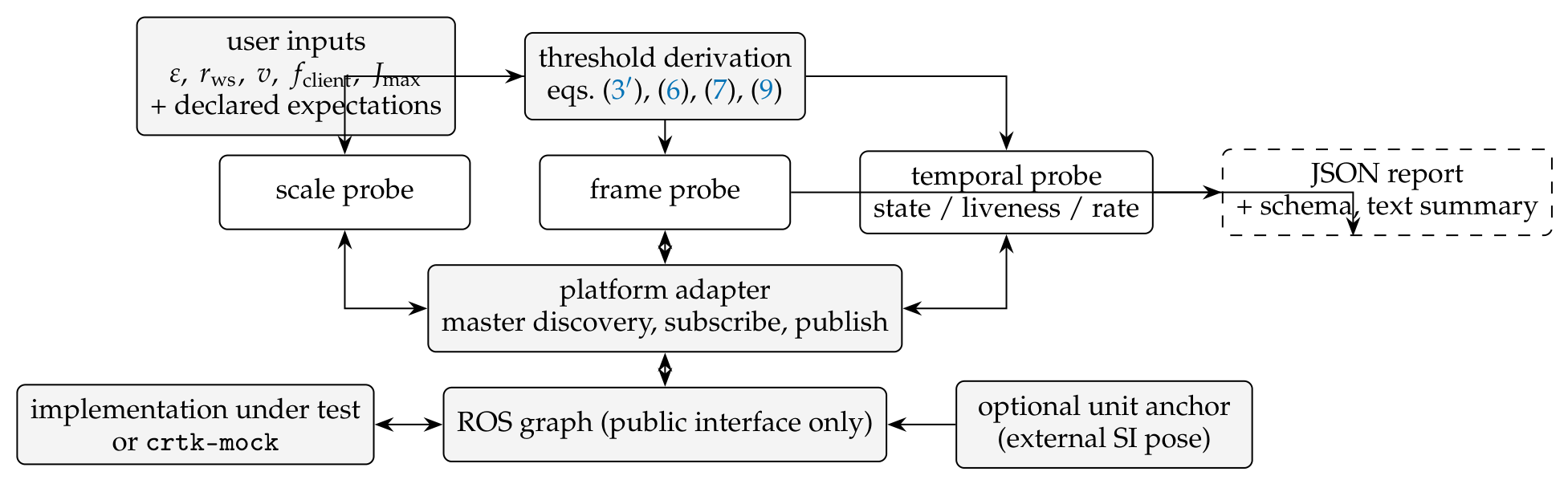
crtk-conformance (version 0.1.4) is an installable Python package and ROS node that discovers, where the interface exposes them, the three bindings of an arm namespace through its public interface and reports a three-valued outcome per class, together with the channels each outcome rests on. The design follows from the model and from the client-relative relation of Section 3. Black box: the probes see only what a porting researcher sees—topics discovered through the ROS master, messages received, commands published—and contain no platform-specific code. No hidden adaptation: the suite never transforms, rescales or re-times a command on the user’s behalf; a divergence is reported, not compensated. Declared expectations: the client states, in a small configuration file, what it was authored against—for the spatial class an expected binding transform between the unqualified topics and local/ (the identity, a given transform, or none), for the dimensional class the unit it assumes, and for the temporal class whether it requires or forbids an operating-state machine, what it expects when its command stream stops (hold, release, fault) and the rate it needs, which the tool uses only to scale a diagnostic—and every decision is taken against that declaration. Three-valued outcome: conformant means that the discovered binding satisfies the declared expectation to within the client’s tolerance, on the channel the probe observed and under the assumptions the report records; divergent means the declared expectation is violated beyond it, established by an interval that lies entirely beyond the tolerance, never by a bound that merely could exceed it; undetermined is returned whenever the interface does not expose what the decision needs, whenever data are missing or ambiguous, whenever the interval of the decision quantity straddles the tolerance, whenever the expectation is claimed beyond what was tested, and whenever no expectation was declared. With no expectation there is no conformance verdict, only a report of what was discovered; a binary verdict, or a verdict against an implicit reference, would convert absence of evidence into evidence of conformance. Thresholds as inputs: the user states a task-space tolerance , a workspace radius , a nominal speed v, and the rate and jitter bound of the client under test; every decision threshold is derived from these through the model—the exact maximum (5) of the residual between the discovered and the expected transform over the ball of radius for the spatial class, (7) at for the dimensional class and (8) for the temporal class; (10) gives the required period against which the rate diagnostic is reported, not decided. The probes also contain implementation constants that determine whether an estimate can be formed but never where the decision boundary lies (settle windows, a stamp-pairing window, a response timeout, the matching tolerance of the rate estimator, minimum trial counts); each is a command-line option with a documented default, most are scaled at run time from the measured resting noise of the feedback channel, and all are recorded in the report. Intervals that are meant to contain the truth: the spatial decision quantity carries an interval propagated from joint confidence regions of the transform parameters; the scale estimate is a mean of per-trial ratios with a Student-t interval; the liveness timeout is reported as an interval built from the trials that passed and tripped with explicit allowances for what the probe cannot observe; the rate estimator constructs a heuristic interval from value-matched setpoint samples, reported as a diagnostic rather than a guaranteed source-age enclosure or a conformance decision (below). Table 3 states every rule with its channel, its decision quantity, its interval and the assumptions it records; each construction is described below and its coverage or soundness is measured in Section 7.1 rather than assumed. The defaults are trials for the frame and scale probes and for the liveness sub-probe, and the rate sub-probe uses one one-second window per nominal rate. Figure 4 shows the components. The suite implements exactly three probes, one per binding class; the temporal probe has three sub-probes. There are no others.
- Frame probe.
The probe is passive: it publishes nothing. When the implementation exposes both measured_cp and local/measured_cp, it pairs samples by time stamp within a pairing window, forms the quotient per trial, averages it over trials, and reports and . Its translations are read in the unit the client declares for the interface (expected_unit_m, one metre by default); this is a precondition of the spatial verdict, not something the probe establishes, and it is recorded in the report as an assumption [A]. If the client declared an expected transform , the per-trial residuals are formed and the decision quantity is the exact maximum positional error (5) of their mean over the ball of radius . Its interval is propagated rather than re-centred: the translation residuals and the rotation-vector deviations from the mean rotation each receive a Hotelling confidence ellipsoid (Bonferroni-split so that the pair holds at 95 %), and since (5) is 1-Lipschitz in t and -Lipschitz in the rotation vector, the largest radii of the two ellipsoids bound how far the true maximum can lie from the estimate; the interval is conservative under its model, is infinite (and the verdict undetermined) with fewer than four trials, and its empirical coverage is reported in Section 7.1. That model is not distribution-free and independence of the trials alone does not give it: the Hotelling construction is exact for iid multivariate-normal trial errors and for no wider class in finite samples, and the rotation-vector deviations from the mean rotation are treated as Euclidean-normal samples under a small-angle approximation. The report states both with every spatial verdict, together with the largest per-trial rotation deviation it saw; a client whose trial errors are heavy-tailed must not read the interval as a 95 % region (the released tests include a mixture-noise case in which its coverage is 43 %), and the coverage figures of Section 7.1 are empirical results for the Gaussian configurations they were measured in. The verdict is positional: it compares that interval with , and orientation enters only through its positional effect over the ball unless the client declares a separate orientation tolerance, which is then checked on the residual rotation angle with its own interval. A dVRK configured as the specification’s own example is thus conformant for a client that declares that configuration and divergent for a client that declares the identity, which is what the relation of Section 3 requires. Without a declared expectation the transform is reported and the outcome is undetermined. When local/ is absent the binding cannot be verified through the interface, whatever the expectation, and the probe returns undetermined with an inventory of the frame_id strings and of any T_b_w or /tf information it found. What the probe tests is the relation between two feedback topics; it does not command anything, so it never observes the frame in which servo_cp is interpreted. That the command shares the binding of measured_cp is a source-supported assumption for the dVRK and the SRC (Section 4) [A], and a controller with a correct feedback transform and a wrong command transform would pass this probe; the report states this scope with every spatial verdict.
- Scale probe.
The probe commands displacements along each axis, with a step scaled to at least twenty times the measured resting noise, streams each goal at the client’s rate during the settle time and the measurement window as a servo client would (a single command followed by silence would let a silence-triggered stop policy act inside the window), and measures each displacement as the difference of averaged windows before and after the settle time. It reports two estimators that Section 5.2 shows answer different questions: the internal ratio , which equals one for any uniform scale and detects only a mismatch between command and measurement scaling or a tracking deficit, and, only if the user supplies an out-of-band anchor topic carrying an independent SI pose of the same tool, the anchored estimate , which is decided against the unit the client declares. A trial in which no motion is detected is counted as a non-response rather than as a zero-length displacement, and fewer than three responding trials leave the class undetermined. Without an anchor the dimensional outcome is undetermined by construction.
- Temporal probe.
Three sub-probes. The state precondition sub-probe records whether an operating_state topic exists, sends a command in the disabled state and after enable/home, and reports whether the implementation responded to and attained each, together with the enable latency. The liveness sub-probe first measures its own timing resolution—the sleep and publication granularity of the interpreter, the feedback period, and the response latency of the implementation, re-enabling the implementation if a stop policy fired during the measurement—and reports a resolution floor below which a gap cannot be resolved; it then streams commands, stays silent for a gap, records the pose during the gap, sends one command and observes the response. The classes are observational: held, drifted (with the onset and speed of the departure estimated inside the gap), rejected or faulted, not observable, and, for the probe as a whole, held through the tested range. None of these names a mechanism, and a stationary pose during a silence is compatible with a hold, with a released but balanced mechanism and with a longer timeout; the report says what was observed and the expectation schema gives every stop expectation an explicit horizon (Table 3). For a tripping policy, bisection between realised gaps on a monotonic clock yields, per trial, the largest silence g that passed and the smallest h at which the trip became visible (the realised gap for a rejection or fault, the onset of the departure for a drift), and the timeout is reported as an interval under a deterministic-timeout model: from every passing trial and (fault, rejection) or (drift onset, which cannot precede the policy) from every tripping one. Here is the response latency of that trial’s own last streamed command, which the probe measures by ending each stream with an observable half-step whose response it times; G is one feedback period, the granularity at which the implementation is assumed to evaluate its policy [A]; is zero for a rejection or fault and, for a drift, the time the pose needs to cross the hold tolerance at the slowest estimated drift speed plus a feedback period; and L is the allowance for the one transaction that draws no response, the post-gap command that the policy has already rejected. L is the client-supplied one-way latency bound if one is given; otherwise the probe uses the largest response latency it observed in the run, which is a sample maximum and not a bound, and every interval and verdict that rests on it is labelled conditional on that allowance in the report [A]. The interval is the intersection over trials, a set of bounds with no intersection is reported as such, and the estimate is formed only with at least three trials, a known allowance and a lower end above the resolution floor. A policy that trips at the smallest resolvable gap is reported as an upper bound, not a number. A fault or drift expectation is then decided on two independent conditions, each against the interval: that the policy fires within the horizon the client claims (the interval lies entirely within it; violated when it lies entirely beyond, or when no trip was observed within tested silences that cover the horizon), and that the client’s own stream survives it, (8) with the period plus jitter bound below the interval’s lower end; either condition straddling its boundary makes the verdict undetermined, and a horizon beyond the tested silences is undetermined only when no trip was observed within them. A hold expectation is satisfied by a hold through the tested range up to the claimed horizon and violated by a trip evidenced within it; a release expectation is undetermined from the pose alone.
The rate sub-probe commands separable targets at several nominal rates and archives its send times, message stamps and samples of setpoint_cp, the channel CRTK describes as the current setpoint to the low-level controller ([15], api-robot-motion.rst, lines 111, 164, 534–549) [P]. The quantity of interest is the applied command’s source age, , where is the send time of the command applied at t. If its identity and application history were known, the temporal error would be bounded by under the trajectory model of Section 5.3. Update cadence and the fraction of observed target values do not establish that age: a FIFO buffer can update regularly while applying increasingly old commands.
The released estimator infers source identity by matching each sample to the nearest target already sent at its receipt time. It constructs a candidate interval by assigning that target’s send time to the sample and extending the inferred hold to the next sample. Before the first inferred match it counts the oldest unmet intent from the first send. The window ends at the first post-send match to the final target, or at observation end if no such match occurs. At a final-target match the estimator uses the preceding sample to bracket the inferred application time rather than charging the entire publication interval to the final command. These are estimator conventions, not independently observed application events.
Three limitations prevent a conformance verdict. First, matching values does not prove provenance: an earlier queued command can coincide with a current target. CRTK already requires header.stamp on setpoint_cp, referring to the setpoint_js definition of time associated with the last servo command, but it does not unambiguously require an echo of the originating client’s send timestamp ([15], lines 446–448, 541) [P]. The probe uses value matching, not such an identifier contract. Second, even with correct identity, an age measured at feedback receipt includes transport delay: for send time s, publication time p and receipt time r, . A receipt-side age is not a lower bound on publication-side age without an appropriate delay allowance. Third, extending a matched source time between snapshots requires an ordering or observation-completeness assumption: piecewise-constant values alone cannot exclude an unobserved return to an older command. The probe’s match checks cannot establish that assumption.
Consequently, the candidate interval is a heuristic diagnostic, not a guaranteed enclosure of true source age, and the released rate sub-verdict is always undetermined. Section 7.1 measures its failures in both directions against command identities in the mock’s event log. A client stall can coexist with a finite diagnostic interval and is reported separately. Feedback target crossings in measured_cp remain diagnostics, not evidence of command execution. A declared rate requirement therefore prevents a wholly conformant aggregate temporal outcome; a separately violated state or stop requirement can still make that outcome divergent.
- Reporter and adapter.
Results are written as JSON validated against a published schema, with every estimate, confidence interval, decision basis, declared expectation, run parameter and raw per-trial observation. Discovery uses the ROS master’s system state, counting a topic as present only if a node other than the probe currently publishes or subscribes to it. The release supports ROS 1 only; there is no ROS 2 backend and no PDF output.
Table 3.
Decision rules of crtk-conformance 0.1.4. Every verdict is taken against the client’s declared expectation on the channel named; the report records the assumptions of the last column with the verdict. The rate class (last row) carries no verdict: it is always undetermined, with the heuristic source-age interval attached as a diagnostic. : tolerance; : workspace radius; ; , : the client’s rate and jitter bound.
Table 3.
Decision rules of crtk-conformance 0.1.4. Every verdict is taken against the client’s declared expectation on the channel named; the report records the assumptions of the last column with the verdict. The rate class (last row) carries no verdict: it is always undetermined, with the heuristic source-age interval attached as a diagnostic. : tolerance; : workspace radius; ; , : the client’s rate and jitter bound.
| Class (channel) | Decision quantity; interval | conformant / satisfied iff | divergent / violated iff | undetermined when; assumptions recorded |
|---|---|---|---|---|
| Spatial (ttmeasuredcp vs. ttlocal/) | exact maximum error (5) of the mean residual over ; interval from Hotelling regions of the translation and rotation-vector residuals (Bonferroni, Lipschitz propagation) | upper end (and, if declared, the residual rotation angle interval within the orientation tolerance) | lower end | no local/; ; interval straddles ; no expectation. Assumes iid multivariate-normal trial errors, small-angle rotation deviations, the declared interface unit, and that servo_cp shares the binding of measured_cp |
| Dimensional (anchor vs. ttmeasuredcp) | anchored scale against the declared unit; Student-t interval of per-trial ratios; error (7) at | over the interval | beyond over the interval | no anchor; fewer than three responding trials. Assumes the anchor’s accuracy; the internal ratio is reported, never decided on |
| Temporal: state (ttoperatingstate, ttservocp) | response to a command before and after enable/home | observed gating matches the declaration | contradicts it | declaration any; behaviour not observable |
| Temporal: stop (ttmeasuredcp during silence) | observed class; (fault, rejection) or (drift) | hold: held through the tested range up to the claimed horizon. Fault/drift: class observed, interval within the horizon, and lower end | hold: trip evidenced within the horizon. Fault/drift: no trip within tested silences covering the horizon, interval beyond the horizon, or upper end | release (always); horizon beyond the tested silences with no trip; interval or margin straddles; trials; unknown allowance; inconsistent bounds. Assumes a deterministic timeout evaluated at least once per feedback period G; L = client bound, else the run maximum of observed latencies (conditional); drift speed during detection |
| Temporal: rate | candidate source-age interval from value-matched samples; diagnostic comparison with | never | never | always undetermined. A diagnostic requires a setpoint channel and sufficient matched samples; client stalls do not necessarily prevent one. Source identity is inferred, receipt age includes transport delay, and inter-sample ordering is unverified. The interval is not a guaranteed enclosure. |
- The mock node.
crtk-mock is a kinematic CRTK-compatible node whose semantic bindings are parameters: a binding transform between the arm base and the frame of the unqualified topics, with or without local/ and T_b_w topics; a unit ; an operating-state machine that can reject commands when disabled; a liveness timeout with fault or release semantics, the latter with or without drift; execution and publishing rates with latest-wins subsampling; acceptance of only every k-th command; setpoint_cp carrying the goal its execution loop currently applies, or withheld; a latest-wins or an ordered (FIFO) command buffer; queued response delay and jitter; message drops; position and orientation measurement noise; a stamp skew between the two pose topics; a bounded speed that makes the pose move continuously toward its goal; and switches that remove topics. It publishes its ground-truth pose in metres on an out-of-band topic that serves as the validation oracle and, in validation only, as the unit anchor, and it writes an event log of every command it receives, applies, drops, ignores, supersedes or discards, keyed by the command’s own message stamp, from which the validation derives the temporal truth independently of the probe. Five presets emulate the documented behaviours of Section 4—a CRTK-literal reference, the JHU PSM2 configuration, SRC v1.0.0, SRC v2.0.0, and the AMBF object-layer watchdog exposed directly—each assembled from the cited values; parameters that no artifact declares, such as the drift speed of the release preset, are labelled validation parameters. Nothing measured against a preset is a measurement of the platform it emulates.
Figure 4.
Architecture of crtk-conformance. Thresholds are derived from the user’s tolerance through the error model and every verdict is taken against the client’s declared expectations; the probes reach the implementation only through the ROS graph; the unit anchor is optional and external.
Figure 4.
Architecture of crtk-conformance. Thresholds are derived from the user’s tolerance through the error model and every verdict is taken against the client’s declared expectations; the probes reach the implementation only through the ROS graph; the unit anchor is optional and external.
7. Validation: Implementation Verification and Live Runs
This section reports two kinds of measurement and keeps them apart. Section 7.1 runs the suite against crtk-mock with injected ground truth ([M-ref]); it can establish that the probes recover injected divergences, that the intervals they report contain the injected truth at the stated rate, and that the decision rule behaves as specified around the boundaries the model defines. It says nothing about any platform, because the mock implements the bindings by construction. Section 7.2 runs the same suite, unchanged, against the released SRC v1.0.0 and v2.0.0 CRTK interfaces executing on the AMBF simulator ([M-live]); it establishes what those interfaces expose and do in one stated environment, and where they expose too little to decide. Measurements below come from archived runs and their analysis scripts; the scale-boundary and rate-diagnostic corrections are independently recomputed in the accompanying analysis supplement. The original archive is retained unchanged, and the tables include the stated reporting corrections. The truth labels of the campaign are the quantities the verdicts claim to decide, or, for the rate class, the quantity this paper reports as a diagnostic—the exact maximum error (5) of the injected transform, the injected unit scale, the injected timeout, and the source age of the applied setpoint reconstructed from the mock’s own event log rather than from its configuration—not the tool’s own decision statistics; the earlier campaigns are archived in the repository and are used for no claim.
7.1. Verification Against the Reference Node
The campaign ran inside the same container as the live runs (Ubuntu 20.04, ROS Noetic built from pinned sources, Python 3.8; wall time 64.2 min on a private ROS 1 master over loopback) with , , , a 100 Hz client and , with seeds independent of every earlier campaign. Each experiment declares the expectation the client under test would hold, so that a conformant outcome is possible only where the paper’s rule allows one. Table 4 and Figure 5 summarise the results.
- Frame probe.
With the identity declared as the expected binding, the injected transform was swept over 120 runs of trials. With no noise the injected transform was recovered to floating-point precision (largest error 3e-14 mm); at mm noise the translation error was mm on average and mm at most; at mm noise the translation error was mm on average and mm at most; the rotation angle error stayed below 1e-13 degrees (noise on position only in this grid); the sensitivity floor—the norm of the averaged transform when the injected transform is zero—was mm at mm, mm at mm; and the interval of the exact maximum error contained the true value in 120 of the 120 runs (median half-width mm at mm noise). The tolerance sweep from 0.05 to 50 mm, labelling a run divergent when the exact maximum error (5) of its injected transform exceeds the tolerance, gave a false-conformant count of 0 and a false-divergent count of 0 at every one of the 61 tolerances, with at most 3 of 120 runs undetermined at any tolerance. A stress case of a mm translation along a 0.3 rotation axis, whose exact maximum over the ball is mm while the bound (3) is mm, was conformant ([0.874, 0.874] mm at 0 mm noise), conformant ([0.847, 0.902] mm at 0.02 mm noise), undetermined ([0.767, 1.020] mm at 0.1 mm noise) at ; the same translation perpendicular to the axis, which attains the bound, was divergent ([1.224, 1.224] mm), divergent ([1.183, 1.251] mm), divergent ([1.090, 1.336] mm). Against the JHU binding (, ) the client-relative rule behaved as Section 3 requires: a client that declared that transform was conformant in all 3 runs (residual mm at most); a client that declared the identity was divergent in all 3 runs; with no declared expectation the outcome was undetermined with the transform reported ( 2 mm, 2 mm, mm for an injected 2 mm/5 binding); and with local/ removed it was undetermined whatever the declaration. On an interface whose unit is m, a client that declared the JHU transform together with that unit was conformant (exact maximum error [0.000, 0.000] mm), and one that declared the transform in metres was divergent ( 1800 mm), the residual being the transform itself misread by a factor of ten: the spatial verdict is only as good as the unit precondition the client states. Orientation noise of 0.1, 0.5 and 2 on the measurement gave conformant at 0.1∘ ([0.000, 0.524] mm), undetermined at 0.5∘ ([0.000, 1.921] mm), undetermined at 2∘ ([0.000, 12.496] mm): the interval widens with the orientation noise, since a rotational uncertainty of costs of positional slack over the ball, and the verdict passes to undetermined rather than to a false one; a stamp skew of up to 80 ms between the two pose topics gave conformant with 0 unpaired samples at 2 ms, conformant with 0 unpaired samples at 30 ms, conformant with 4 unpaired samples at 80 ms, the pairing window rejecting the samples once the skew exceeds it. With an orientation tolerance of 1 declared, a residual rotation of 0.1 noise was conformant (orientation conformant) and a binding rotated 3 away from the declared transform was divergent (orientation divergent; the positional effect of 3 over the ball, mm, is itself beyond ).
- Coverage of the spatial interval.
The interval of Section 6 was checked by replication: 60 replicate runs of the probe (independent noise draws from one seeded stream per configuration), each with trials, at four injected residuals—zero, a translation of exactly 1 mm on the decision boundary, the 0.3 stress case above with orientation noise, and a 2 mm/5 residual well beyond it—under mm ( mm for the rotation case) per-axis noise. The intervals contained the true exact maximum error in 60 of 60 at the boundary residual (true error 1 mm); 60 of 60 at the large residual (true error mm); 60 of 60 at the rotation residual (true error mm); 60 of 60 at the zero residual (true error 0 mm); the median interval width was mm (boundary), mm (large), mm (rotation), mm (zero); the verdict at was boundary: 0/0/60 conformant/divergent/undetermined; large: 0/60/0 conformant/divergent/undetermined; rotation: 48/0/12 conformant/divergent/undetermined; zero: 60/0/0 conformant/divergent/undetermined; false divergent 0, false conformant 0 over all replicates. The interval is conservative under its model, and the price is paid in undetermined verdicts near the boundary rather than in false ones. These counts are empirical results for the four Gaussian-noise configurations they were measured in and not a distribution-free guarantee: for a mixture-noise stress case (ten trials whose x error is m with probability 0.95 and m otherwise, plus 1 m Gaussian noise) the same interval covers the true zero error in 43 % of replicates, and the released test suite keeps that case as a documented limitation.
- Scale probe.
Nine unit scales from 0.1 to 10 at three noise levels, 27 runs of noise-scaled steps (the campaign runner set nine trials per run; the probe’s default, and the live runs of Section 7.2, use ten). The internal ratio averaged 1.0000 across all runs (range 0.9983 to 1.0018) for injected scales spanning two orders of magnitude: the estimator every intuitive unit test would use cannot see the divergence, as Section 5.2 predicts. With the anchor, was exact with no noise; within 0.25 % of the injected value at mm noise; within 1.09 % of the injected value at mm noise. At the decision boundary is ; the 27 runs gave 6 conformant, 19 divergent and 2 undetermined ( at 0 mm, at 0.02 mm). One of the 19, run S_si_020 ( at mm noise), lies exactly on that boundary: its model error is , which the closed boundary of the rule counts as conformant, and its anchored interval, [1.0102, 1.0156] (error interval [1.016, 1.562] mm), does not contain the injected scale, so the verdict divergent is a false divergent—one interval miss in 27 runs at the fixed 1 mm threshold. The analysis script stores that truth as a floating-point value marginally above 1 mm (0.0010000000000000009 m) and therefore does not count the case, so the fixed-threshold counts it generates, here and in the campaign-wide summary below, understate the false-divergent count by one; the original released analysis does not correct this; the accompanying analysis supplement recomputes the fixed-threshold result using the declared decimal configuration. Over the tolerance sweep, whose 61-point logarithmic grid contains no point at exactly 1 mm, the false-conformant and false-divergent counts were 0 and 0, with at most 4 of 27 undetermined. The control without an anchor returned undetermined with an internal ratio of 1; a client declaring the m unit of the SRC v1.0.0 emulation was conformant () against it, which is the relation’s verdict for a client authored against that interface; anchor noise of 0.02, 0.1 and mm gave divergent, divergent, divergent for the injected ; and with 10 % and 50 % of commands dropped by the implementation the streamed goal still reached it (0 of 9 and 0 of 9 non-responding trials). The scale sweep demonstrates the estimator with a privileged oracle under uniform scaling; it says nothing about recovery with an uncertain real anchor.
- Rate sub-probe.
The campaign comprised 180 nominal rate windows, spanning execution and publishing rates, noise, every-k-th command acceptance (), withheld setpoint feedback, random drops, delayed and jittered commands, FIFO buffers, stale-value feedback and a 20 Hz channel. Twenty windows did not send separable targets; 160 were scored against the mock’s event record. Of those, 150 produced finite candidate intervals and ten lacked the setpoint channel. The client was classified as rate-limited in 39 of the 160 scored windows, including 36 of the 150 with finite intervals; the other three were channel-withheld cases. These limitations are reported separately from diagnostic accuracy.
The candidate interval contained event-log truth in 98 of 150 windows. At the archive’s 1 s comparison tolerance, 48 failures were at the lower end and four at the upper end. The upper-end failures were T_fifo_120 at 1000 Hz, T_fifo_50 at 500 Hz and 1000 Hz, and T_fifo_80 at 1000 Hz. Their reported intervals were respectively [898.644, 900.420], [787.482, 789.459], [1284.007, 1285.488] and [1138.413, 1139.489] ms, against oracle ages of 1350.563, 1350.583, 1350.560 and 1350.614 ms. Joining send stamps to apply events shows no current-window command applied during any of these windows, although value matching reports 124, 15, 66 and 100 applications. Earlier queued commands coincide with current sweep targets, producing incorrect source associations. Before any current-window application, the oracle follows the declared oldest-unmet-intent convention, measuring age from the first send; it does not estimate the older command’s complete pre-window age.
Other configurations demonstrate where the heuristic is informative without establishing a general guarantee. At the client’s 100 Hz, the noise-free 120 Hz latest-wins loop gave [14, 24] ms against truth 19 ms; a 50 ms application delay gave [60, 70] ms against truth 66 ms. The 20 Hz channel gave [10, 60] ms at 100 Hz and [4, 54] ms at 500 Hz, against truths 12 ms and 4 ms. Sparse publication widens those candidate intervals, while the FIFO failures demonstrate that a candidate upper end can also be too low. The diagnostic is neither a guaranteed enclosure nor consistently biased in one direction. Version 0.1.4 issues no rate conformance verdict for any of these cases.
- Liveness and stop behaviour.
Fault-mode timeouts of 12, 15, 20, 30, 50, 100, 250, 500 and 1000 ms were injected, the first three chosen around the client’s own margin requirement of 15 ms (period plus jitter bound). The probe’s measured resolution floor in the container was 10.6 ms (median over the 34 runs; range 10.5–50.8 ms) and its latency allowance 5–18 ms (the largest response latency observed in each run, used conditionally where the client supplied no bound; 50 ms in the 20 Hz-feedback case). Timeouts of 50, 100, 250, 500, 1000 ms gave the intervals [29.8, 68.9], [80.7, 115.2], [231.3, 266.9], [481.5, 522.1], [988.0, 1022.9] ms ( bisection runs each), all classified faulted; 12, 15, 20 and 30 ms gave faulted with status undetermined (interval lower bound not above the resolution floor). The intervals contained the injected timeout in 23 of 23 of the estimates with status ok, 22 of them labelled conditional on the run-maximum latency allowance (the remaining interval uses the client-supplied bound); their median width was ms. Against a client needing 15 ms, the sub-verdict was undetermined at 12–30 ms, satisfied at 50 ms (undetermined wherever the 15 ms need falls inside the interval or the interval was not formed; satisfied only where it lies below the interval’s lower end). Release-mode timeouts of 0.1 and s with drifts of 20 and 5 mm/s (validation parameters) were classified drifted with intervals [78.4, 101.3] ms for s at 20 mm/s; [80.2, 102.9] ms for s at 5 mm/s; [479.1, 501.3] ms for s at 20 mm/s; [486.5, 507.3] ms for s at 5 mm/s; the drift expectation was satisfied and the hold expectation violated in all 4; the same release without drift was classified held through range, satisfied for a hold expectation and undetermined for a release expectation, which is all the pose can show. The horizon rule was exercised with the client’s claim placed below, at and above the policy: a 250 ms fault policy against “fault within 0.1, 0.25 and s” gave violated at s (interval [231.0, 266.7] ms), undetermined at s (interval [232.5, 267.3] ms), satisfied at 1 s (interval [232.1, 266.8] ms), and a s release with drift against “drift within 0.2, 0.5 and s” gave violated at s (interval [487.7, 502.2] ms), undetermined at s (interval [475.9, 501.3] ms), satisfied at s (interval [487.1, 501.6] ms); a stress-test replay case—a s fault policy against “fault within s”—was violated (interval [988.2, 1022.9] ms). With no timeout the probe reported held through the tested range up to s and a hold expectation was satisfied; the same observation against a hold claimed up to 3 s was undetermined; a fault policy at 2 s, beyond the tested range, was classified held through range, satisfied for a hold claimed to s, undetermined for a fault expectation with the default horizon (no fault within the tested silences) and undetermined for a fault claimed within 3 s, beyond what was tested. With a 300 ms response delay the latency allowance widened the interval to [489.0, 824.0] ms (allowance 313 ms; satisfied); with feedback at 20 Hz the granularity allowance did the same ([152.3, 372.6] ms with ms, classified faulted); with a client-supplied latency bound of 5 ms the interval was [231.5, 260.1] ms, satisfied under that supplied bound and the stated timeout model.
- State precondition, regression cases and presets.
The CRTK-literal and dVRK-emulation presets rejected the disabled-state command and executed after enable/home (enable latency 10.7–16.4 ms); the SRC emulation has no operating_state topic and executed immediately. Against these the three declarations gave dvrk-jhu-psm2/discover: undetermined; dvrk-jhu-psm2/forbidden: divergent; dvrk-jhu-psm2/required: conformant; src-v1/discover: undetermined; src-v1/forbidden: conformant; src-v1/required: divergent; reference without state topic/required: divergent; reference/discover: undetermined; reference/forbidden: divergent; reference/required: conformant. The five regression configurations, with every class declared, gave delay-50ms-jitter-20ms: conformant/conformant/divergent; drop-50: conformant/conformant/divergent; missing-cp: undetermined/undetermined/undetermined; noisy: undetermined/undetermined/undetermined; nolocal: undetermined/conformant/undetermined. Under the general definition—conformant while the injected truth violates the expectation, or conformant while no expectation was declared—the campaign produced 0 false-conformant run(s), and 0 false-divergent run(s) (divergent while the injected truth satisfies the expectation) as counted by the analysis script; that count omits the boundary case S_si_020 described above, which is a false divergent under the rule’s closed boundary, so the correct fixed-threshold count is one false divergent. Each preset was run with no expectation, which gave undetermined in every class, and with the expectation a client authored against that platform’s own documentation would declare (SI units, hold on silence up to the tested range, the documented state machine, a rate requirement, and for the dVRK emulation the JHU transform), which gave the outcomes the emulated artifacts imply (ambf-object-watchdog: undetermined/conformant/divergent; dvrk-jhu-psm2: conformant/conformant/conformant; src-v1: undetermined/divergent/undetermined; src-v2: undetermined/conformant/undetermined; reference: conformant/conformant/undetermined; spatial/dimensional/temporal): the SRC v1.0.0 emulation is dimensionally divergent for a client that believes its documentation, the AMBF-watchdog emulation is temporally divergent for a client that expects a hold, the reference and dVRK emulations are conformant for their own clients in the spatial and dimensional classes, and the SRC emulations’ rate expectation is undetermined because they publish no setpoint_cp. Two temporal outcomes in these lists rest on the rate sub-verdict that the archived campaign’s code still decided and that this paper does not validate: the delay case’s divergent (state and stop behaviour satisfied; rate violated) and the dVRK emulation’s conformant (rate satisfied). Under the released rule, which decides no rate class, both are undetermined; the archived outcomes are reported as generated. Executing absolute and incremental commands against the JHU binding and comparing the mock’s ground-truth error with the model gave agreement to better than 1 m (largest difference 1e-14 mm) at every point in Figure 3; this checks that the model and the mock implement the same kinematics and nothing more.
- Interpretation of the rate diagnostic.
The event log provides an independent reference for evaluating the estimator’s source associations and window conventions. At the final target, charging age at receipt can include an extra publication interval; the estimator’s preceding-sample convention reduces that effect when the inferred identity is correct. It does not resolve reused-target ambiguity or hidden transitions between samples. Strictly positive lower-end excess occurred in 49 of 150 windows, one below the 1 s comparison tolerance; the largest excess was ms outside client stalls and ms during them, with a 95th percentile of ms over all windows. These are discrepancies between an estimate and the event oracle, not independent measurements or bounds on transport delay. The four upper-end failures show that small observed lower-end excess cannot justify the diagnostic as a reliable enclosure. The manuscript’s accompanying analysis supplement recomputes these counts from the unchanged archive. Preliminary and superseded campaigns remain archived and support no result reported here.
7.2. Live Runs Against the Released SRC Interfaces
The suite was run, unchanged, against the CRTK interface script of SRC v1.0.0 (commit 158b554e) and v2.0.0 (03befbf1), each executing on the AMBF ambf-2.0 branch (16a81518) that both releases require, headless under Xvfb in the container of Section 7.1, with each release’s own launch arguments and with one arm (PSM1) and no scene. No source file of either release or of AMBF was modified. Because both releases start with the tool at or within millimetres of the remote centre of motion, where Cartesian control is singular, the arm was first moved by servo_jp to approximately 42 % of its insertion range ( interface units for v1.0.0, whose joint limit is 2.40; for v2.0.0, whose limit is m) and every probe ran from there. Three runs were taken per release: with no expectation, with the expectation a client authored against the SRC’s own documentation would hold (identity binding, SI units, no state machine, hold on silence claimed up to the 2 s tested, rate required), and with the expectation a client authored against the dVRK would hold (state machine required). The three runs differ in the declared expectation only; they are not replicates of one condition. Table 5 summarises the runs. The runs reported here were taken with the probes frozen at the commit of Section 7.1, after that campaign; the earlier live attempts, which exposed classifier weaknesses on the gravity-loaded v1.0.0 controller that the mock could not show, are archived in the repository and are used for no claim.
- What the interfaces expose.
Both releases publish measured_cp, measured_cv, measured_js, T_b_w and accept servo_cp and servo_jp; neither publishes local/measured_cp, setpoint_cp, operating_state or accepts state_command or servo_cr, and neither publishes /tf. measured_cp carries frame_id psm1/baselink and T_b_w carries world in both, at 119.2 and Hz (the 120 Hz publishing loop of Section 4). These are the rows of Table 1 that concern presence and naming, now observed rather than read.
- Temporal class.
With no operating_state topic, servo_cp executed without any state transition in every run of both releases. Both releases held position through every tested silence: the pose stayed within the hold tolerance for gaps up to 2 s ( per run; drift 0.006–0.016 interface units on v1.0.0 against a hold tolerance scaled to its feedback jitter, at most mm on v2.0.0) and the post-gap command was acted on, which the report states as held through the tested range; a stop policy with a longer timeout is not excluded, and the AMBF object-layer timeout of Section 4 was not observed through this interface within 2 s. The measured resolution floor was 9–12 ms and the median response latency 53–70 ms (v1.0.0) and 49–74 ms (v2.0.0). The rate class is undetermined on both releases, as it is everywhere, and here not even the diagnostic could be formed: neither publishes setpoint_cp, so there is no applied-setpoint channel to bracket the source age on, and the feedback crossings the report still lists are a diagnostic (v1.0.0: no window run, targets not separable at its feedback noise; v2.0.0: 0–26 crossings per 50–500 commands at 50– 500 Hz), not evidence of execution. Consequently the SRC-authored expectation is undetermined on both releases (state and stop behaviour satisfied up to the claimed 2 s, rate undecidable) and the dVRK-authored expectation is divergent on both (state machine required, none exposed). The internal execution rate of Table 1 remains an artifact claim.
- Dimensional and spatial classes.
No independent SI anchor exists inside the simulator’s interface, so the dimensional class is undetermined in every live run, as Section 5.2 says it must be. What the interface does show is consistent with the artifact claims. The internal command/measurement ratio on v2.0.0 was 1.0001 [1.0000, 1.0002], 1.0001 [1.0000, 1.0002] and 1.0001 [1.0000, 1.0001] over the three runs (, 5 mm steps; a 10 mm step settled to 1 m), and on v1.0.0 1.28 [1.01, 1.55], 1.21 [0.99, 1.44] and 0.99 [0.80, 1.18] with steps scaled to its noise. The v2.0.0 ratios are near one, which says nothing about the unit; the v1.0.0 ratios differ from run to run with wide intervals, and they do not establish the ratio either way: under that release’s gravity-loaded joint controllers the arm does not settle on the commanded step within the measurement window, so each ratio measures the fraction of the step attained in that run’s tracking state, and the probe reports the ratio without deciding on it. At the matched insertion the reported tool position had norm 0.967 interface units on v1.0.0 and m on v2.0.0, each within 0.1 % of the release’s own forward kinematics of the reported joints; the ratio is 11.2 rather than 10 because v2.0.0 places its control point at the yaw joint where v1.0.0 adds 0.106 units, and with the control point matched every length constant of v1.0.0 is ten times its v2.0.0 counterpart. The spatial class is undetermined on both releases, whatever the expectation, because local/measured_cp is absent; the probe reports the frame_id strings and the T_b_w transform it found.
- The feedback-invisible offset.
Section 4 predicted from the source that the joint errors the SRC injects are invisible through the interface. Both releases print the errors they draw at start-up; subtracting the simulator’s own joint state from measured_js gave their negatives to on both releases (v1.0.0: errors , offsets ; v2.0.0: errors , offsets ), and measured_cp equalled the forward kinematics of the de-perturbed joints. The offset exists between the reported and the simulated state and is not reachable by any black-box probe, which is the point of the paragraph.
- What the live runs establish.
They turn the presence, naming, state-topic and de-perturbation rows of Table 1 from artifact claims into observations for two released versions, they show the interfaces holding position for silences up to 2 s with no exposed state machine, and they show that the spatial binding, the unit and the command rate cannot be decided through these interfaces—which is the tool’s designed answer, not a failure of the run. No determinate positive verdict about a frame, a unit or a rate was obtained on released software: the only determinate live verdicts are the two adverse temporal ones, which rest on the absence of a state machine that the source already shows. The two releases are versions of one implementation family, not independent platforms. The runs establish nothing about the dVRK, nothing about the SRC under other launch options or on other hosts, and nothing about physical hardware.
Table 4.
Verification against crtk-mock ([M-ref]; tolerance 1 mm, ; archive validation/v0.1.3/mock). Rows summarize archived outputs with the boundary and diagnostic-accuracy corrections stated in the text.
Table 4.
Verification against crtk-mock ([M-ref]; tolerance 1 mm, ; archive validation/v0.1.3/mock). Rows summarize archived outputs with the boundary and diagnostic-accuracy corrections stated in the text.
| Quantity | Runs, trials | Result |
|---|---|---|
| Frame: , identity declared | 120, | 0 (0 mm noise); mean 0.007, max 0.014 mm (0.02 mm noise); mean 0.039, max 0.087 mm (0.1 mm noise) |
| Frame: interval of the exact maximum error (5) | 120 | contains the truth in 120/120; median half-width 0.131 mm at 0.1 mm noise |
| Frame: decisions over mm (truth = exact maximum) | 120 | false-conformant , false-divergent , undetermined |
| Frame: coverage replicates (zero / boundary / rotation / large residual) | 4 × 60, | boundary 1.000 (width 0.264 mm); large 1.000 (width 0.251 mm); rotation 1.000 (width 0.196 mm); zero 1.000 (width 0.166 mm); false divergent 0, false conformant 0 |
| Frame: stress case mm, / same | 3 / 3 | conformant, conformant, undetermined / divergent, divergent, divergent |
| Frame: JHU binding, declared / identity / none / no local/; unit 0.1 declared / assumed SI | 10; 2 | conformant / divergent / undetermined / undetermined; conformant / divergent |
| Scale: internal ratio, | 27, | mean 1.0000 (0.9983–1.0018); no-anchor control undetermined |
| Scale: anchored | 27, | exact (0 mm); % (0.02 mm); % (0.1 mm) |
| Scale: decisions over the sweep | 27 | false-conformant 0, false-divergent 0, undetermined ; at the fixed 1 mm threshold one false divergent (S_si_020, boundary case, not counted by the script) |
| Rate: source-age bracket vs event-log truth, diagnostic only, no verdict (k-th acceptor, FIFO, delay, drops, stale channel, sparse channel, channel withheld) | 180 windows, 150 with a bracket | candidate interval contains truth 98/150; 48 lower-end and 4 upper-end misses at 1 s tolerance; client-limited: 36/150 with intervals, 39/160 scored |
| Liveness interval (fault) | 9, | 50→[29.8, 68.9], 100→[80.7, 115.2], 250→[231.3, 266.9], 500→[481.5, 522.1], 1000→[988.0, 1022.9] ms; 12 ms: undetermined, 15 ms: undetermined, 20 ms: undetermined, 30 ms: undetermined; contains the truth in 23/23 (22 conditional); floor 11–51 ms |
| Liveness: eq. (8) margin, client needs 15 ms | 5 | 12 ms: undetermined, 15 ms: undetermined, 20 ms: undetermined, 30 ms: undetermined, 50 ms: satisfied |
| Liveness: horizon below / at / above the policy (fault s; drift s); stress-test replay (fault 1 s, claim s); client latency bound | 3 / 3 / 1 / 1 | fault: 0.1 s → violated, 0.25 s → undetermined, 1 s → satisfied; drift: 0.2 s → violated, 0.5 s → undetermined, 1.5 s → satisfied; replay violated; bound: satisfied [231.5, 260.1] ms |
| Liveness: release with drift / without drift / no timeout / horizon beyond tested / policy beyond tested | 4 / 2 / 1 / 1 / 2 | drifted [78.4, 101.3], drifted [80.2, 102.9], drifted [479.1, 501.3], drifted [486.5, 507.3] ms; held through range (hold satisfied, release undetermined); hold satisfied; hold-to-3 s undetermined; fault-at-2 s: hold satisfied, fault undetermined |
| State precondition | 10 | as emulated; enable latency 10.7–16.4 ms; required / forbidden / discover verdicts per preset |
| Regression cases and presets, all classes declared | 5; 10 | false-conformant runs: 0; false-divergent runs: 0 as counted by the script (1 with S_si_020, see the scale rows) |
| Model check (JHU binding, ) | 19 points | mock error equals model to better than 1 m (largest difference 1e-14 mm) |
Table 5.
Live runs against the released SRC interfaces on AMBF ([M-live]; archives validation/v0.1.3/live-src-v1, live-src-v2). Rows summarize the archived live runs.
Table 5.
Live runs against the released SRC interfaces on AMBF ([M-live]; archives validation/v0.1.3/live-src-v1, live-src-v2). Rows summarize the archived live runs.
| Quantity | Runs, trials | Result |
|---|---|---|
| SRC v1.0.0: topics, frame_id, publish rate | 1 | present: measured_cp, servo_cp, measured_js, servo_jp, T_b_w, measured_cv; absent: local/measured_cp, setpoint_cp, local/setpoint_cp, servo_cr, operating_state, state_command; psm1/baselink, T_b_w in world; 119.2 Hz |
| SRC v1.0.0: state, stop behaviour, rate | 3 runs, | no operating_state; executed without state machine; held through range up to 2 s; floor 9–11 ms, latency 53–70 ms; rate undetermined (targets not separable) |
| SRC v1.0.0: internal ratio, unit | 3 runs, | 1.280 [1.007, 1.552], 1.215 [0.992, 1.437], 0.990 [0.797, 1.183]; unit undetermined (no anchor) |
| SRC v1.0.0: reported − simulated joints; at | 1 | (-0.0679, +0.0010, -0.0485) (injected errors); 0.9672 units |
| SRC v1.0.0: verdicts (spatial/dimensional/temporal) | 3 runs | no expectation: undet./undet./undet.; SRC-authored: undet./undet./undet.; dVRK-authored: undet./undet./div. |
| SRC v2.0.0: topics, frame_id, publish rate | 1 | present: measured_cp, servo_cp, measured_js, servo_jp, T_b_w, measured_cv; absent: local/measured_cp, setpoint_cp, local/setpoint_cp, servo_cr, operating_state, state_command; psm1/baselink, T_b_w in world; 119.7 Hz |
| SRC v2.0.0: state, stop behaviour, rate | 3 runs, | no operating_state; executed without state machine; held through range up to 2 s; floor 9–12 ms, latency 49–74 ms; rate undetermined (no applied setpoint channel) |
| SRC v2.0.0: internal ratio, unit | 3 runs, | 1.000 [1.000, 1.000], 1.000 [1.000, 1.000], 1.000 [1.000, 1.000]; unit undetermined (no anchor) |
| SRC v2.0.0: reported − simulated joints; at | 1 | (+0.0431, +0.0116, +0.0017) (injected errors); 0.0861 units |
| SRC v2.0.0: verdicts (spatial/dimensional/temporal) | 3 runs | no expectation: undet./undet./undet.; SRC-authored: undet./undet./undet.; dVRK-authored: undet./undet./div. |
Figure 5.
Verification against crtk-mock (all [M-ref], archive validation/v0.1.3/mock). (a) Translation estimation error versus injected translation () at three noise levels; the no-noise series lies at the plotting floor. (b) Anchored scale estimate (solid) and internal ratio (dashed) versus injected scale: the internal ratio stays at one for every scale. (c) Liveness timeout intervals versus injected timeout for fault policies (circles at the midpoint, bars spanning the interval) and release-with-drift policies (squares); the dashed line is the measured resolution floor; crosses mark estimates reported undetermined. (d) False-conformant (FNR), false-divergent (FPR) and undetermined rates of the frame and scale decisions as the tolerance is swept from 0.05 to 50 mm, with positives defined as truly divergent runs.
Figure 5.
Verification against crtk-mock (all [M-ref], archive validation/v0.1.3/mock). (a) Translation estimation error versus injected translation () at three noise levels; the no-noise series lies at the plotting floor. (b) Anchored scale estimate (solid) and internal ratio (dashed) versus injected scale: the internal ratio stays at one for every scale. (c) Liveness timeout intervals versus injected timeout for fault policies (circles at the midpoint, bars spanning the interval) and release-with-drift policies (squares); the dashed line is the measured resolution floor; crosses mark estimates reported undetermined. (d) False-conformant (FNR), false-divergent (FPR) and undetermined rates of the frame and scale decisions as the tolerance is swept from 0.05 to 50 mm, with positives defined as truly divergent runs.
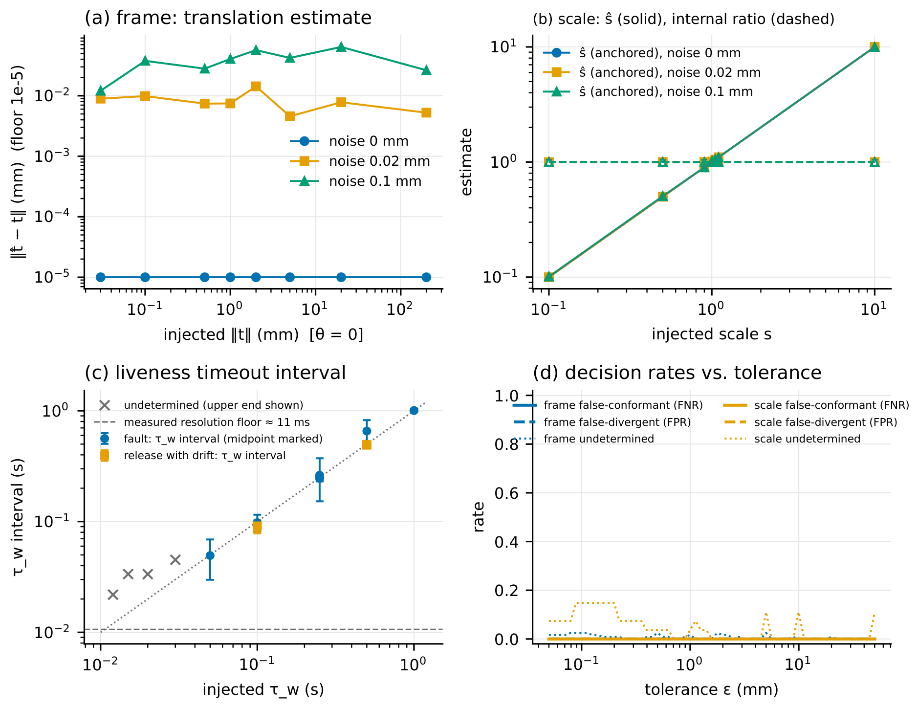
8. Discussion, Limitations and Threats to Validity
- Evidentiary boundary.
No measurement in this paper was taken on a physical dVRK or Raven-II, and none on any AMBF or SRC installation other than the two containerised releases described in Section 7.2. Section 4 is an analysis of released artifacts; Section 5 is a model whose illustrative magnitudes come from a released configuration file; Section 7.1 verifies the probes against a mock that we wrote; Section 7.2 measures two released SRC interfaces executing on AMBF, headless, on a two-core host, with the arm and launch options stated there. The mock verification establishes that the probes recover injected divergences, that their intervals contain the injected truth at the measured rates, and that the decision rule behaves as specified around its boundaries. The live runs establish what the released SRC interfaces expose and do under those conditions: they turn the SRC rows of Table 1 that concern topic presence, frame naming, state topics and de-perturbed feedback into observations, and they show where the interface exposes too little to decide, which is the tool’s designed answer. They contain no positive frame, unit or rate verdict on released software, and they do not establish anything about the dVRK, whose rows remain artifact claims, nor about the SRC under other launch options, hardware or graphics conditions. The paper is therefore an artifact audit and an identifiability study with a verified prototype instrument; it is not a demonstration of that instrument’s principal capabilities on a platform other than our own reference node. Released artifacts license claims about released artifacts: we say that released implementations, configurations and specifications exhibit different semantics, and we say how two of them behaved in one stated environment, and no more.
- What the artifact audit and probes establish.
Reading constants in their architectural context distinguishes three easily conflated properties: the SRC’s factor-of-ten unit convention, its RCM-origin arm-base frame without a local/ topic, and the separation between the dVRK’s controller-link watchdog and command-stream liveness. Similar care is needed for probe outputs. An upper error bound is not proof that a tolerance is exceeded; feedback target crossings do not establish command execution; estimator repeatability is not estimation uncertainty; setpoint cadence is not freshness; and an observed stop class does not decide a horizon that its timeout interval straddles. Section 6 states the channels and assumptions of each rule, and Section 7.1 evaluates the intervals against injected truth, including the failures of the rate diagnostic.
- Black-box blindness and the scope of a verdict.
The suite detects divergence at the interface; it cannot localise a cause inside a controller, distinguish an architectural choice from a bridge-layer artifact, or detect defects that appear only near singularities or joint limits, since it probes with small motions away from both. A miscalibrated kinematic model that agrees with the interface’s own feedback is invisible to it, exactly as a uniform unit scale is. The suite is a conformance instrument that screens for gross semantic mismatch before more expensive white-box, dynamic and hardware-in-the-loop verification; it is not a certification. A passing report establishes a narrower contract than the definitions of Section 3 describe: for the spatial class, that the relation between measured_cp and local/measured_cp, read in the unit the client declared, agrees with the declared transform to within the tolerance over the ball, at 95 % under the interval’s assumptions, with the frame of servo_cp assumed from the source; for the dimensional class, that the anchored scale agrees with the declared unit, with the anchor’s accuracy taken on trust; for the temporal class, that the observed state precondition and the observed stop class and timeout interval agree with the declared expectation up to the claimed horizon, under a deterministic-timeout model evaluated at least once per feedback period and, where no latency bound was supplied, conditionally on a run-maximum latency allowance. The heuristic source-age interval, where available, is reported alongside the temporal outcome and establishes no additional contract (Section 6). Each report lists these channels and assumptions with its verdicts. The observation horizon deserves emphasis: a hold observed for two seconds is a hold observed for two seconds, and a release policy cannot be told from a hold by the pose alone.
- Kinematics only.
The model and the mock are kinematic. They do not represent contact dynamics, force or wrench semantics, tissue interaction, cable backlash, gravity compensation or actuator saturation—all of which shape executed motion on a physical dVRK [14] and all of which are part of any sim-to-real transfer [7,8]. Uniform geometric scaling does not in general preserve dynamic equivalence: for geometrically similar rigid bodies of fixed density, mass scales as and rotational inertia as ; contact and actuation forces depend on the corresponding physical model and cannot be inferred from geometric scaling alone. A scaled simulator is therefore not merely a rescaled one, and a dimensional divergence of the kind in D2 has dynamic consequences outside our model.
- Configuration dependence.
The magnitude of D1 is a deployment parameter. The 200 mm and 150 figures come from one released console file and describe one installation; the model applies to any transform and the illustrative numbers do not.
- Model and interval assumptions.
The Gaussian, independent-jitter form (9) is the paper’s most fragile step and is presented as illustrative; the bounded-jitter form (8) with a measured bound is what a practitioner should use. The ideal hold bound (10) assumes source age at most for the intended trajectory; piecewise-constant updates alone do not establish it. Interpolation has different tracking properties and is outside that bound. The rate diagnostic assumes associations between target values and feedback samples that can fail, and cannot verify ordering between samples. It also depends on the implementation reporting its applied setpoint truthfully. The spatial model assumes a rigid binding; a binding changed at run time (set_base_frame) is a time-varying T that the probe would see as inconsistency across trials. The spatial interval assumes iid multivariate-normal trial errors and a small-angle treatment of the rotation deviations, and it is conservative under those assumptions only: independence alone does not give the guarantee, and heavy-tailed errors reduce its coverage far below nominal, as the released mixture-noise test shows. The liveness interval assumes a deterministic timeout evaluated at least once per feedback period and, for the one transaction that draws no response, a transport latency no larger than a client-supplied bound or, failing that, the largest response latency observed in the run—a sample maximum, so that every verdict resting on it is labelled conditional; a set of bounds that contradict the model is reported as such rather than as an interval. With correct source identity, receipt-side age includes feedback transport delay. With incorrect identity, either end of the candidate interval may miss the event-oracle age, as the FIFO results demonstrate. Neither the lower-end excess statistics nor the candidate interval establish a bound for a deployed controller. These limitations are why the rate class remains undecided.
- Versions age.
Every divergence is stated against a pinned version, and SRC v2.0.0 already changed D2. The claim is about a class of failure that the specification permits, not a permanent property of any project.
- Threats to the validation.
The mock implements the bindings by construction, so agreement between the model and the mock’s executed errors checks the implementation of the model, not the physics of any platform, and the false-positive and false-negative rates of Section 7.1 characterise the decision rule around boundaries that the same model defines. The mock verification ran in one container on loopback networking; latency and jitter on a distributed deployment would be larger, and the sensitivity floors are specific to the injected noise. The probe’s Python send loop limits the client rates it can present, which the rate sub-probe measures and reports rather than attributes to the implementation. The unit anchor in validation is the mock’s own ground truth; on a real platform the anchor’s accuracy bounds the estimate. The live runs have their own threats: the simulator ran headless on two virtual cores at its released physics rate, the arm’s tracking under the v1.0.0 release’s gravity-loaded joint controllers was poor enough that the probes’ steps had to be scaled to the feedback jitter, and the runs used one arm without a task scene; another host or another scene could change the timing figures, though not the presence or absence of topics, frame names, state topics or the de-perturbation of the feedback, which are properties of the released code. The earlier live attempts are archived alongside the reported runs because they exposed classifier weaknesses on this noisy, gravity-loaded controller that the mock could not show, configuration problems of our own (probing at the singular home pose, a start-up race in the released interface), or were superseded when a later mock campaign exposed a further probe defect; the probes were corrected and the runs repeated, the corrections are listed in the change log, and the earlier attempts are used for no claim. The probes were revised after seeing live data and after adversarial examination of their decision rules, which is a form of tuning to the target; what was tuned is the ability to form an estimate and the soundness of the rule, never a decision threshold, and the reported campaign and live runs were taken with the code frozen at one revision after those changes. The counterexamples that drove those revisions are kept verbatim as regression tests, and the rate truth of the campaign is reconstructed from the mock’s event log by a script that never reads the estimator’s output, so that agreement between the two is not built into the analysis. The mock’s event log is still the mock’s own account of itself: it provides a reference against which estimator errors can be identified, not independent evidence that a released implementation reports its applied setpoint truthfully.
- What would strengthen the work.
Positive controls on software other than our own mock: the dVRK software stack in its kinematic-simulation mode, which exposes local/ and setpoint_cp and takes a configurable base_frame, would let the frame probe return a determinate verdict against a known configuration without hardware; an SRC run with a unit anchor external to the simulator would let the dimensional class be decided rather than reported; an anchor derived from documented instrument geometry rather than an external tracker; a physical dVRK or Raven-II run; and a labelled-transition-system model of the CRTK operating-state protocol against which the state-precondition sub-probe could be made a conformance test in the formal sense [25]. A decidable freshness check needs an explicit target quantity and a contract covering source identity, relevant timestamps and clock relationships, and the evidence required between observations. Echoing an originating command identifier or send timestamp resolves provenance only if its semantics are guaranteed; it does not itself remove feedback delay or rule out hidden stale applications. Application or publication timestamps with compatible clock semantics, or justified delay and clock-error bounds, are needed for the corresponding timing claims. Ordering guarantees or sufficiently complete execution-event feedback are additionally needed for an inter-sample enclosure. Section 9 therefore proposes a stronger timing contract rather than a timestamp field alone. Until the positive controls above exist, the determinate verdicts of the tool are verified only against the reference node.
9. Recommendations for the CRTK Specification
Make the required frame name resolvable, and definelocal/normatively for each platform class. The specification already requires measured_cp to name its reference frame; what it does not require is that the name resolve to anything. It should require that the transform between the named frame and the arm-base frame be machine-discoverable—published as a transform, or with the frame_id strings bound to /tf—so that a client can verify the binding rather than trust the string; it should require that distinct frames carry distinct identifiers, so that measured_cp and local/measured_cp never share a frame_id when they differ; and it should state the frame in which a servo_cp goal is interpreted, which today it does not. It should define the semantics of local/, where an implementation provides it, normatively for the applicable platform or robot class instead of by the dVRK example: CRTK also covers systems that have no remote centre of motion, so an RCM-constrained manipulator such as a dVRK PSM may define its local, arm-base frame relative to the RCM, as the released dVRK artifacts do, but that choice cannot be imposed on every platform. The frame probe of Section 6 would then never need to return undetermined for want of a reference.
Require REP-103 SI units on all Cartesian and joint topics in the specification text. The requirement exists downstream in ROS conventions and in the dVRK’s own files; it does not exist in the CRTK text, which is silent on units. A one-sentence normative requirement, and a recommended machine-readable declaration of the unit on the interface, would make D2 a specification violation rather than a convention.
Specify the temporal contract ofservo_*as required interface metadata. Whether an operating-state machine gates commands, whether a command-liveness policy exists and with what timeout, what happens to the setpoint when the stream stops, and the minimum and recommended command rates should be declared per implementation in a discoverable form. ROS 2 quality-of-service deadline and liveliness policies already provide a declarable, middleware-enforced contract for the arrival of a command stream [23], and a ROS 2 CRTK should use them; what they do not express, and what CRTK must add, is the actuation consequence—hold, release or fault—when the stream stops. “Close to the low-level rate” should be replaced by a number or by a published rate topic. For setpoint_cp, the specification already requires a timestamp associated with the last servo command ([15], api-robot-motion.rst, lines 446–448, 541). It should define whether that stamp identifies the originating command, its application, or the feedback sample, and provide separate fields where more than one time is needed. An echoed command identifier or original send timestamp should unambiguously identify the applied command. Timing claims should state the clock relationship and any delay or clock-error bounds. A guarantee over intervals between samples additionally needs defined application ordering or sufficiently complete event feedback. Together these provisions would support freshness checks for an explicitly stated temporal quantity; adding an identifier alone would not make the current diagnostic a sound verdict.
Ship a conformance suite with the specification. A specification with a reference test is harder to misread than one without. We offer crtk-conformance and crtk-mock as a starting point: the mock’s presets are a compact executable statement of what the released artifacts do, and the probes are a compact statement of what a client can and cannot verify.
10. Conclusion
Standardising topic names and message types buys structural conformance, and structural conformance is not semantic conformance. Reading released code, configuration and specification text with the discipline of citing every line, we found the semantic contract of CRTK’s Cartesian and servo topics left to each implementation in three classes, and we found the released implementations disagreeing in each. The error model turns those disagreements into task-space bounds and separates the cases that matter: incremental commands hide a translational frame divergence; closed-loop feedback hides a unit divergence entirely; and a task tolerance constrains allowable source age, yielding a rate requirement under explicit freshness assumptions. The released suite discovers what can be discovered through the interface, decides conformance only against what a client declares it expects, and says undetermined where the interface does not expose enough; its verification against a reference node with injected ground truth reports where it is accurate, how often its intervals contain the truth, and where it cannot decide; and its runs against two released SRC interfaces show it doing on real software what it was designed to do, which on those interfaces is chiefly to return undetermined where they expose too little. Frame identification needs an independently grounded spatial relation, unit identification needs a dimensional anchor, and temporal conformance needs the state and timing evidence appropriate to the declared requirement. Command and feedback consistency alone supplies none of those external guarantees. Structural standardisation therefore cannot by itself deliver the portability it is used for. Its complement is a semantic contract that is declarable by the implementation, discoverable by the client and testable through the interface; semantic portability of control code in surgical robotics depends on that complement, and executable conformance testing of the kind released here is one way to make it checkable.
Code Availability
crtk-conformance 0.1.4, including crtk-mock, the validation harness, the archived outputs of the mock verification (with the mock’s event logs) and of the live SRC runs, the superseded campaigns and preliminary live runs, the complete container recipe with pinned source manifests, the counterexample scripts kept as regression tests, and the table- and figure-generating scripts (which run without ROS), is released under the Apache-2.0 licence [33]; the 0.1.0, 0.1.1 and 0.1.2 archives are retained unchanged. The described version is tag v0.1.4, commit 1538d13, on branch main of https://github.com/DeanDonkov/crtk-conformance, archived at Zenodo under the version DOI 10.5281/zenodo.22711143 [33]. The archived validation outputs of Section 7 were produced by earlier commits of the same repository: the v0.1.3 campaign and live runs by commit 004ef30 (cited in their run records under its pre-publication hash 1c06238, since the repository history was re-authored to a single author before publication without any change to file content), and the 0.1.0–0.1.2 archives by the commits named in the change log; PROVENANCE-REWRITE.md at the repository root maps every cited hash to its current one. Version 0.1.4 changes no measurement, estimator or decision input relative to that freeze; it reports the rate class as undetermined in every case, consistent with the scope of this paper, and keeps the earlier rule under an archival name so that the archived campaign re-derives exactly. The manuscript source package includes the updated evidence ledger and an analysis supplement, ttverifyreporting.py, which recomputes the corrected boundary and diagnostic counts against the archived data without changing them. The repository retains the derivation notes and original recomputation scripts.
Data Availability
No experimental data on physical robots were generated. All measured data are outputs of the probes against the mock node or against the containerised SRC releases and are archived in the repository together with the commands, environment and logs that regenerate them.
Author Contributions
D.D. conceived the study, performed the artifact audit, derived the model, wrote the software, ran the validation and wrote the manuscript. S.S. and P.T. supervised the B.Sc. thesis from which this work is derived.
Funding
This research received no external funding.
Conflicts of Interest
The authors declare no conflict of interest.
Ethics
No human or animal subjects were involved.
Use of AI Tools
Large language model assistants (Anthropic Claude and OpenAI Codex) were used, under the first author’s direction and review, to assist with software implementation, data analysis scripting, literature checking, adversarial review and the drafting and editing of text. The first author reviewed and verified every artifact citation, derivation, measurement and statement, and takes full responsibility for the content.
References
- Kazanzides, Peter; Chen, Zihan; Deguet, Anton; Fischer, Gregory S.; Taylor, Russell H.; DiMaio, Simon P. An open-source research kit for the da Vinci Surgical System. IEEE International Conference on Robotics and Automation (ICRA), 2014; pp. pages 6434–6439. [Google Scholar] [CrossRef]
- Chen, Zihan; Deguet, Anton; Taylor, Russell H.; Kazanzides, Peter. Software architecture of the da Vinci Research Kit. IEEE International Conference on Robotic Computing (IRC), 2017; pp. pages 180–187. [Google Scholar] [CrossRef]
- Hannaford, Blake; Rosen, Jacob; Friedman, Diana W.; King, Hawkeye; Roan, Phillip; Cheng, Lei; Glozman, Daniel; Ma, Ji; Kosari, Sina Nia; White, Lee. Raven-II: An open platform for surgical robotics research. IEEE Trans. Biomed. Eng. 2013, 60(4), 954–959. [Google Scholar] [CrossRef] [PubMed]
- Munawar, Adnan; Wang, Yan; Gondokaryono, Radian; Fischer, Gregory S. A real-time dynamic simulator and an associated front-end representation format for simulating complex robots and environments. IEEE/RSJ International Conference on Intelligent Robots and Systems (IROS), 2019; pp. pages 1875–1882. [Google Scholar] [CrossRef]
- D’Ettorre, Claudia; Mariani, Andrea; Stilli, Agostino; Rodriguez y Baena, Ferdinando; Valdastri, Pietro; Deguet, Anton; Kazanzides, Peter; Taylor, Russell H.; Fischer, Gregory S.; DiMaio, Simon P.; Menciassi, Arianna; Stoyanov, Danail. Accelerating surgical robotics research: A review of 10 years with the da Vinci Research Kit. IEEE Robot. Autom. Mag. 2021, 28(4), 56–78. [Google Scholar] [CrossRef]
- Richter, Florian; Orosco, Ryan K.; Yip, Michael C. Open-sourced reinforcement learning environments for surgical robotics. arXiv 2019, arXiv:1903.02090. [Google Scholar]
- Xu, Jiaqi; Li, Bin; Lu, Bo; Liu, Yun-Hui; Dou, Qi; Heng, Pheng-Ann. SurRoL: An open-source reinforcement learning centered and dVRK compatible platform for surgical robot learning. IEEE/RSJ International Conference on Intelligent Robots and Systems (IROS), 2021; pp. pages 1821–1828. [Google Scholar] [CrossRef]
- Varier, Vignesh Manoj; Rajamani, Dhruv Kool; Tavakkolmoghaddam, Farid; Munawar, Adnan; Fischer, Gregory S. AMBF-RL: A real-time simulation based reinforcement learning toolkit for medical robotics. International Symposium on Medical Robotics (ISMR), 2022. [Google Scholar] [CrossRef]
- Su, Yun-Hsuan; Munawar, Adnan; Deguet, Anton; Lewis, Andrew; Lindgren, Kyle; Li, Yangming; Taylor, Russell H.; Fischer, Gregory S.; Hannaford, Blake; Kazanzides, Peter. Collaborative robotics toolkit (CRTK): Open software framework for surgical robotics research. IEEE International Conference on Robotic Computing (IRC), 2020; pp. pages 48–55. [Google Scholar] [CrossRef]
- Quigley, Morgan; Gerkey, Brian; Conley, Ken; Faust, Josh; Foote, Tully; Leibs, Jeremy; Berger, Eric; Wheeler, Rob; Ng, Andrew. ROS: An open-source Robot Operating System. ICRA Workshop on Open Source Software, 2009; volume 3. [Google Scholar]
- Mars Climate Orbiter Mishap Investigation Board. Mars Climate Orbiter Mishap Investigation Board Phase I Report. Technical report. NASA, November 1999. Available online: https://llis.nasa.gov/llis_lib/pdf/1009464main1_0641-mr.pdf (accessed on 2026-09-02).
- Tolk, Andreas; Muguira, James A. The Levels of Conceptual Interoperability Model. In Proceedings of the 2003 Fall Simulation Interoperability Workshop, Orlando, FL, 2003; p. Paper 03F-SIW-007. [Google Scholar]
- Surgical Robotics Challenge contributors. Surgical robotics challenge. https://github.com/surgical-robotics-ai/surgical_robotics_challenge, tags v1.0.0 (commit 158b554e, 2022-08-19) and v2.0.0 (commit 03befbf1, 2024-07-13), and commit 26bb2f69 (2026-06-19); files under scripts/surgical_robotics_challenge/ as cited in the text, 2024. Accessed. (accessed on 2026-09-02).
- Cui, Zejian; Cartucho, João; Giannarou, Stamatia; Rodriguez y Baena, Ferdinando. Caveats on the first-generation da Vinci Research Kit: Latent technical constraints and essential calibrations. IEEE Robot. Autom. Mag. 2023), which the page references in the text follow. 2025, arXiv:2210.13598v232(2), 113–128. [Google Scholar] [CrossRef]
- Collaborative Robotics Toolkit contributors. CRTK API documentation: robot motion and operating state. 2026-06-03), 2026a. Available online: https://crtk-robotics.readthedocs.io (accessed on 2026-09-02).
- Collaborative Robotics Toolkit contributors. crtk_msgs: ROS message definitions for CRTK. Available online: https://github.com/collaborative-robotics/crtk_msgs (accessed on 2026-09-02).
- Frank, Tobias; Krieger, Axel; Leonard, Simon; Patel, Niravkumar A.; Tokuda, Junichi. ROS-IGTL-Bridge: an open network interface for image-guided therapy using the ROS environment. Int. J. Comput. Assist. Radiol. Surg. 2017, 12(8), 1451–1460. [Google Scholar] [CrossRef] [PubMed]
- Ore, John-Paul; Detweiler, Carrick; Elbaum, Sebastian. Lightweight detection of physical unit inconsistencies without program annotations. In Proceedings of the 26th ACM SIGSOFT International Symposium on Software Testing and Analysis (ISSTA), 2017; pp. pages 341–351. [Google Scholar] [CrossRef]
- Kate, Sayali; Chinn, Michael; Choi, Hongjun; Zhang, Xiangyu; Elbaum, Sebastian. PhysFrame: Type checking physical frames of reference for robotic systems. In Proceedings of the 29th ACM Joint European Software Engineering Conference and Symposium on the Foundations of Software Engineering (ESEC/FSE), 2021; pp. pages 45–56. [Google Scholar] [CrossRef]
- Meeussen, Wim. REP 105: Coordinate frames for mobile platforms. ROS Enhancement Proposal. 2010. Available online: https://www.ros.org/reps/rep-0105.html (accessed on 2026-09-03).
- Santos, André; Cunha, Alcino; Macedo, Nuno; Lourenço, Cláudio. A framework for quality assessment of ROS repositories. IEEE/RSJ International Conference on Intelligent Robots and Systems (IROS), 2016; pp. pages 4491–4496. [Google Scholar] [CrossRef]
- Ferrando, Angelo; Cardoso, Rafael C.; Fisher, Michael; Ancona, Davide; Franceschini, Luca; Mascardi, Viviana. ROSMonitoring: A runtime verification framework for ROS. In Towards Autonomous Robotic Systems (TAROS 2020); Springer, 2020; volume 12228, pp. pages 387–399. [Google Scholar] [CrossRef]
- ROS 2 documentation contributors. About Quality of Service settings. ROS 2 documentation. 02 09 2026. Available online: https://docs.ros.org/en/rolling/Concepts/Intermediate/About-Quality-of-Service-Settings.html; file (accessed on 2026-09-03).
- Nankaku, Akitoshi; Tokunaga, Masanori; Yonezawa, Hiroki; Kanno, Takahiro; Kawashima, Kenji; Hakamada, Kenichi; Hirano, Satoshi; Oki, Eiji; Mori, Masaki; Kinugasa, Yusuke. Maximum acceptable communication delay for the realization of telesurgery. PLoS ONE 2022, 17(10), e0274328. [Google Scholar] [CrossRef] [PubMed]
- Tretmans, Jan. Model based testing with labelled transition systems. In Formal Methods and Testing; Hierons, Robert M., Bowen, Jonathan P., Harman, Mark, Eds.; Springer, 2008; volume 4949, pp. pages 1–38. [Google Scholar] [CrossRef]
- dVRK contributors. sawIntuitiveResearchKit: dVRK arm component. 2026a. Available online: https://github.com/jhu-dvrk/sawIntuitiveResearchKit (accessed on 2026-09-02).
- dVRK contributors. dVRK documentation: coordinate systems, middleware and IO architecture. 2026-09-01), 2026b. Available online: https://dvrk.readthedocs.io (accessed on 2026-09-02).
- dVRK contributors. dvrk_config_jhu: dVRK configuration files for the JHU systems. Available online: https://github.com/dvrk-config/dvrk_config_jhu (accessed on 2026-09-02).
- University of Washington Biorobotics Lab. Raven II surgical robot software, branch crtk. 15 05 2023. Available online: https://github.com/uw-biorobotics/raven2, files (accessed on 2026-09-03).
- Foote, Tully; Purvis, Mike. REP 103: Standard units of measure and coordinate conventions. Available online: https://www.ros.org/reps/rep-0103.html (accessed on 2026-09-02).
- dVRK contributors. sawRobotIO1394: controller-board I/O library. Available online: https://github.com/jhu-saw/sawRobotIO1394 (accessed on 2026-09-02).
- AMBF contributors. AMBF: Asynchronous multi-body framework. 2026-07-15), 2026. Available online: https://github.com/WPI-AIM/ambf (accessed on 2026-09-02).
- Donkov, Dean. crtk-conformance: black-box semantic conformance probes for CRTK/ROS interfaces, and crtk-mock. Software repository, version 0.1.4 (Apache-2.0), tag v0.1.4, commit 1538d13, branch main, https://github.com/DeanDonkov/crtk-conformance; archived at Zenodo, version DOI 10.5281/zenodo.22711143 (all versions: 10.5281/zenodo.22711142), 2026. Published and accessed. (accessed on 2026-09-11). [PubMed]
Figure 1.
Structural signature and semantic binding of one CRTK topic. The signature is what a client can discover through ROS; the binding is what determines the executed motion. The values shown for A and B are the ones documented in Section 4 for a released simulator interface and a released dVRK configuration respectively.
Figure 1.
Structural signature and semantic binding of one CRTK topic. The signature is what a client can discover through ROS; the binding is what determines the executed motion. The values shown for A and B are the ones documented in Section 4 for a released simulator interface and a released dVRK configuration respectively.
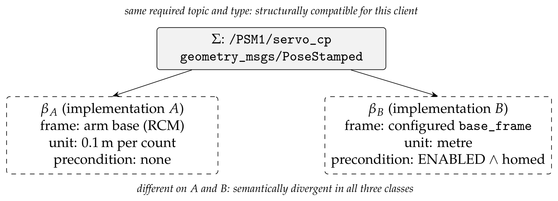
Figure 2.
The three divergence classes. D1: a pose commanded in the arm-base frame is executed in the configured frame. D2: a unit scale maps a commanded path to its homothety about the frame origin. D3: a command stream at rate f against a state precondition, a liveness timeout and, for the illustrated bound, an ideal fresh sample-and-hold.
Figure 2.
The three divergence classes. D1: a pose commanded in the arm-base frame is executed in the configured frame. D2: a unit scale maps a commanded path to its homothety about the frame origin. D3: a command stream at rate f against a state precondition, a liveness timeout and, for the illustrated bound, an ideal fresh sample-and-hold.

Figure 3.
The error model. (a) M1 with the released JHU base frame (, ): absolute-command error by (1) for perpendicular and parallel to the rotation axis, the bound (3), the exact maximum over the ball of radius by (5), and the incremental error (6) with and without rotation; open circles are executed errors measured on the mock node [M-ref] (implementation check, not a platform measurement). (b) M2 error versus distance from the origin for three scales, with mock measurements at [M-ref]. (c) Ideal fresh sample-and-hold bound (10), assuming , for three intended-trajectory speeds, with mm and 1 mm tolerance lines.
Figure 3.
The error model. (a) M1 with the released JHU base frame (, ): absolute-command error by (1) for perpendicular and parallel to the rotation axis, the bound (3), the exact maximum over the ball of radius by (5), and the incremental error (6) with and without rotation; open circles are executed errors measured on the mock node [M-ref] (implementation check, not a platform measurement). (b) M2 error versus distance from the origin for three scales, with mock measurements at [M-ref]. (c) Ideal fresh sample-and-hold bound (10), assuming , for three intended-trajectory speeds, with mm and 1 mm tolerance lines.
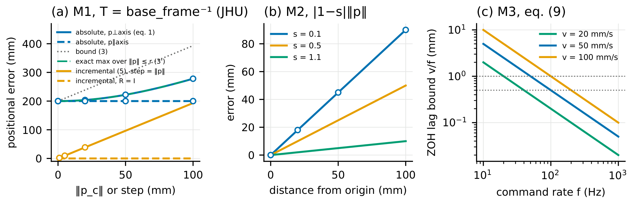
Table 2.
Error-behaviour classification of the three divergences (derived, Section 5). “No” in the last column means the client’s loop closes on numbers that agree with its commands while the executed motion is wrong.
Table 2.
Error-behaviour classification of the three divergences (derived, Section 5). “No” in the last column means the client’s loop closes on numbers that agree with its commands while the executed motion is wrong.
| Divergence | Error law | Behaviour | Visible to a client whose only feedback is measured_cp through the same binding? |
|---|---|---|---|
| D1, absolute, | constant, configuration-scaled | no: , feedback equals command | |
| D1, absolute, | (1)–(5), | constant plus position-dependent | no: position and orientation both hidden |
| D1, incremental | (6) | proportional to step; zero if | no; and zero effect for |
| D2 | (7), homothety | proportional to distance from origin | no: invariant; needs a unit anchor |
| D3, state precondition | threshold | no motion until the state is reached | yes: the command has no effect |
| D3, liveness | threshold at | fault: no motion until recovery; release: mechanism-dependent; hold: last setpoint kept | fault: yes; release: only if the mechanism moves; hold: nothing to see |
| D3, rate | ; (10) if | continuous, age-dependent | partially, as lag between setpoint and feedback |
Disclaimer/Publisher’s Note: The statements, opinions and data contained in all publications are solely those of the individual author(s) and contributor(s) and not of MDPI and/or the editor(s). MDPI and/or the editor(s) disclaim responsibility for any injury to people or property resulting from any ideas, methods, instructions or products referred to in the content. |
© 2026 by the authors. Licensee MDPI, Basel, Switzerland. This article is an open access article distributed under the terms and conditions of the Creative Commons Attribution (CC BY) license (http://creativecommons.org/licenses/by/4.0/).
Copyright: This open access article is published under a Creative Commons CC BY 4.0 license, which permit the free download, distribution, and reuse, provided that the author and preprint are cited in any reuse.