
Submitted:
10 September 2026
Posted:
10 September 2026
You are already at the latest version
Abstract
Conventional valve-controlled hydraulic excavator boom drive systems suffer from low energy conversion efficiency and severe throttling losses. To address this issue, this paper proposes a pump-controlled digital hydraulic drive system based on a Direct Energy Recovery Digital Pump (DERDP). The DERDP integrates hydraulic pumping and boom potential energy recovery within a single unit, enabling both energy recuperation and precise flow regulation. An AMESim simulation model of the system is developed and validated against experimental measurements from a dedicated hardware-in-the-loop test bench. Using the validated model, the operational characteristics are investigated under varying boom load pressures, pump displacement fractions, and motor displacement fractions; the drive and energy recovery efficiencies are systematically evaluated across different operating conditions. Simulation results show that the boom energy recovery efficiency reaches 50%–60%. These findings offer practical guidance for implementing digital hydraulic solutions in construction machinery.
Keywords:
digital hydraulic drive system
; direct energy recovery digital pump (DERDP)
; excavator boom
; energy recovery efficiency
1. Introduction
The global construction machinery industry is undergoing a comprehensive transition toward electrification, high energy efficiency, and carbon neutrality [1]. As the most widely used construction equipment, hydraulic excavators suffer from severe energy dissipation dominated by hydraulic system losses [2,3]. In typical digging cycles, boom movement accounts for 30%–45% of total energy consumption. Restricted by inherent throttling losses of conventional valve-controlled circuits, the overall energy conversion efficiency is limited to only 20%–30% [4]. To overcome this efficiency bottleneck, extensive efforts have been devoted to optimizing the dynamic performance and energy-saving capability of boom drive systems [5].
Electrical energy recovery topologies convert gravitational potential energy into electrical energy for battery storage, yet multi-stage energy conversion inevitably limits round-trip efficiency [6]. By contrast, hydraulic energy recovery schemes store recuperated energy directly in accumulators and reuse it in subsequent actuation cycles, reducing intermediate conversion links and energy losses [7,8]. As an advanced digital hydraulic solution, digital displacement pump (DDP) technology eliminates conventional throttling losses by independently controlling the on–off states of individual plunger chambers, offering flexible digital regulation and superior energy-saving potential [9,10,11]. Consequently, DDP-integrated boom drive systems, with fewer conversion stages and higher control accuracy, have become a promising technical route for high-efficiency digital construction machinery [12,13].
DDP technology has evolved from theoretical verification to practical engineering application in excavator systems. Existing studies have validated its prominent energy-saving performance. A multi-actuator DDP system achieved over 30% fuel savings [14], while the DEXTER project realized a 21% fuel economy improvement on a 16-ton excavator via optimized control strategies [15]. Danfoss reported a peak electro-hydraulic conversion efficiency of 89.0% for digital pump systems [16]. Real-duty-cycle simulations further demonstrated a maximum energy reduction of 24.8% and a full-cycle system efficiency of 54.6% [17,18]. For boom potential energy recuperation, digital hydraulic drive and energy recovery circuits have achieved projected fuel savings of 53%–58% for 18-ton excavators [19,20].
Nevertheless, current DDP-based boom energy recovery systems adopt separated pump and motor configurations. Energy is stored in accumulators during boom lowering and released through independent pumping procedures during boom lifting, leading to excessive hydraulic components and high system complexity. To address this limitation, this paper proposes a Direct Energy-Recovery Digital Pump (DERDP) with integrated pumping and energy-recuperation functionalities. The DERDP adopts an independent valve-timing strategy to physically decouple the dedicated energy-recovery (ER) port from the main discharge (P) port. During boom lowering, high-pressure fluid from the boom cylinder enters selected plunger chambers through the ER port. The converted mechanical power is transmitted via the common eccentric shaft to assist other plungers in charging the accumulator. During boom lifting, accumulator pressure energy is fed back through the ER port to provide auxiliary motor torque. This integrated architecture effectively reduces component count and simplifies system configuration [21,22]. This study systematically investigates the operating characteristics and energy efficiency of the proposed DERDP system under varying load pressures and displacement fractions.
The remainder of this paper is structured as follows. Section 2 introduces the working principle of the DERDP and the hydraulic design of the boom drive system. Section 3 presents the development of the AMESim simulation model and its experimental validation. Section 4 investigates the operational characteristics and energy efficiency of the system under various operating conditions. Section 5 summarizes the key findings.
2. Design of a Digital Hydraulic Drive System for a Boom
2.1. Introduction to the Working Principle of DERDP
The configuration and graphical symbol of the DERDP—the core component of the boom digital hydraulic drive system are shown in Figure 1. The DERDP mainly consists of a high-pressure port (P), an energy recovery port (ER), a low-pressure tank port (T), check valves, high/low-pressure distribution valves, plunger assemblies, and a pump shaft. During operation, the eccentric wheel is driven by the motor, causing the plungers to reciprocate and cyclically vary the volume of each sealed plunger chamber.
When energy recovery is inactive, the high-pressure distribution valve remains fully closed. As the plunger chamber volume increases during the suction stroke, fluid is drawn from the low-pressure port T, with check valve 4 serving as an anti-cavitation replenishment valve. During the discharge stroke, the chamber volume decreases, compressing the fluid to a high-pressure state and delivering it to the load through port P, thereby completing the mechanical-to-hydraulic energy conversion. The output flow rate is regulated by adjusting the closing timing of the low-pressure distribution valve during the compression phase.
Under energy recovery operation, subsets of plungers run in pump mode while others operate in motor mode. High-pressure fluid targeted for recovery flows into plunger chambers through the ER port throughout the suction stroke. This incoming pressurized fluid drives plunger reciprocation and rotates the common eccentric shaft. Recovered hydraulic energy is thereby converted into shaft mechanical power to assist other plungers performing high-pressure discharge, achieving direct in-unit energy recovery and reuse.
Figure 2 illustrates the single plunger unit hardware and associated valve switching control logic. Each unit includes a plunger pair, high-pressure distribution valve, low pressure distribution valve, and check-valve assembly. By modulating the switching timing of valve groups over plunger suction and discharge strokes, three distinct operating modes are realized: pump mode, motor mode, and energy recovery mode (Figure 3).
In pump mode, low-pressure tank fluid fills plunger chambers in the suction stroke; pressurized flow is supplied to external loads in the discharge stroke, consistent with conventional fixed displacement plunger pump behavior. In motor mode, high-pressure fluid originating from the boom cylinder enters the plunger chamber on the suction stroke to generate reciprocating plunger motion and output mechanical torque; during discharge, the chamber connects to the tank to expel low-pressure fluid. Within energy recovery mode, recovered high-pressure fluid enters via the ER port during suction. Pressurized fluid actuates plungers and spins the eccentric shaft, cooperating with the main drive motor to deliver auxiliary shaft power for discharge-stroke plungers. Hydraulic energy is transformed into mechanical shaft power and reused directly inside the pump hardware to realize direct energy recuperation.
Mode transitions and performance tuning are accomplished via precise timing control of the two distribution valves. Motor-mode valve timing for non-recovery conditions is visualized in Fig. 2(b). On the discharge stroke, the high-pressure distribution valve stays closed and the low-pressure distribution valve remains open, diverting all chamber fluid back toward the tank circuit. On the suction stroke, the two switching valves toggle alternately. Adjusting the opening duration of the high-pressure distribution valve modulates high-pressure inflow volume through the ER port, enabling continuous tuning of boom lowering velocity.
By adjusting the pump/motor displacement fraction, the opening and closing states of the high- and low-pressure distribution valves are controlled according to the plunger position, thereby modulating the motor and pump displacements. The top dead center of the plunger corresponds to point A (D), and the bottom dead center to point C (F). During the discharge stroke from C to A, the high-pressure distribution valve remains closed throughout; the low-pressure distribution valve opens from C to B and closes from B to A, with the segment B–A constituting the effective discharge stroke. When point B coincides with A, the pump displacement is zero; when B coincides with C, the pump operates at full displacement. The pump displacement is thus regulated by adjusting the closing timing of the low-pressure distribution valve (the position of point B). During the suction stroke from F to D, the high-pressure distribution valve is open and the low-pressure distribution valve is closed from D to E, allowing oil to enter the plunger chamber through the ER port; from E to F, the high-pressure valve closes and the low-pressure valve opens, allowing oil to be drawn in through port T. When point E aligns with D, the motor displacement is zero; when E aligns with F, the motor operates at full displacement. By adjusting the position of point E, the motor displacement and consequently the flow rate into the digital pump can be regulated. The effective plunger strokes for the different operating modes are summarized in Table 1.
2.2. Design of Digital Hydraulic Drive Systems
The schematic diagram of the digital hydraulic drive system for the boom is shown in Figure 4. The system comprises motor 1, a digital pump with direct energy recovery capability 2, a safety relief valve 3, two-position three-way directional control valves 4 and 5, a shut-off valve 6, an accumulator 7, a boom cylinder 8, check valves 9 and 11, and a backpressure relief valve 10.
During boom lowering with energy recovery activated, valves 5 and 6 open while valve 4 closes, connecting the pump discharge port to the accumulator. High pressure fluid derived from boom’s gravitational potential acts upon the DERDP ER port during the suction phase, driving shaft rotation and generating high pressure output flow at port P. For boom lifting under energy recovery operation, valve 4 opens to connect the boom cylinder rodless chamber to port P, while valve 5 closes to route the accumulator to the ER port. Pressurized accumulator fluid enters DERDP plunger chambers through the ER port during the suction phase and contributes shaft torque together with the electric motor for boom upward actuation.
When boom lowering proceeds without energy recovery, zero net flow exits the DERDP P port. Valve 6 closes and valve 5 opens; fluid exiting the boom rodless chamber passes through ER into DERDP to govern descent speed. During non-recovery boom lifting, valves 5 and 6 remain closed. The DERDP draws oil solely through tank port T and delivers pressurized flow from port P to drive the boom cylinder. This pump-controlled architecture regulates boom velocity by tuning the relative pump-to-motor displacement fraction.
In the digital hydraulic boom drive system, when energy recovery is inactive, the DERDP operates solely in motor mode during boom lowering to control the lowering speed and operates exclusively in pump mode to drive boom lifting. Figure 5 presents the operational schematic when the boom is undergoing energy recovery. Figure 5(a) illustrates the conversion of the boom’s gravitational potential energy into hydraulic energy during the lowering process. Under this operating condition, the boom acts as a power source that supplies energy to the digital pump, while the accumulator recovers and stores this energy. Figure 5(b) shows the release of high-pressure hydraulic fluid stored in the accumulator during the lifting process; this fluid, acting together with the motor, supplies energy to the digital pump, driving the boom upward to achieve the reuse of the recovered energy.
3. Development and Validation of a Simulation Model for a DHDSB
3.1. Simulation Model Development
Taking the single plunger as the core functional unit, a single-plunger unit model of the Direct Energy Recovery Digital Pump (DERDP) was first developed in the AMESim simulation environment, as shown in Figure 6(a). This unit model consists of a cam mechanism, a mass-friction-endstop module, a plunger pair assembly, and a volumetric leakage model. In contrast to the check valve-based flow distribution scheme adopted in conventional plunger pumps, the proposed model replaces the conventional suction and discharge check valves with a high-speed on/off valve assembly (one 2/2-way valve and one 2/3-way valve per plunger) to implement digital flow distribution control and enable direct energy recovery. Five single-plunger units were integrated in parallel to form the complete component-level DERDP model. Building on this component-level model, the DERDP is further coupled with the control valve assembly, accumulator, boom hydraulic cylinder, and excavator mechanical structure to establish the system-level simulation model of the digital hydraulic boom drive system, as illustrated in Figure 6(b). The key parameters of the core model components are summarized in Table 2. To ensure that the simulation conditions align with engineering practice, the scope of the boom drive system simulation is defined based on the typical working cycle of a backhoe excavator. The complete operation sequence for a single boom cycle is depicted in Figure 7. A standard working cycle comprises four sequential stages: (1) boom lifting and repositioning, (2) dipper arm extension (pre-digging), (3) boom lowering and digging, and (4) bucket curling. Consistent with the core research objective of energy recovery and reuse, the boom lowering phase is the primary operating condition for gravitational potential energy recovery, while the boom lifting phase is the main application scenario for recovered energy utilization. This stage classification provides the engineering basis for the subsequent simulation analysis of operational characteristics and energy efficiency.
3.2. Simulation Model Validation
An experimental test bench is constructed to validate the simulation model (Figure 8). The platform integrates the hydraulic drive system, excavator mechanical structure, electrical system, and a hardware-in-the-loop real-time control unit. The pump outlet and energy recovery port connect to the directional valve’s P and T ports, whose A and B ports link to the accumulator and boom cylinder rodless chamber, respectively. Key component parameters are listed in Table 3. The boom cylinder was instrumented with pressure transducers on both chambers, a displacement sensor between piston rod and barrel, a torque sensor at the motor-pump interface, and an encoder on the motor shaft for speed measurement.
Experimental tests were conducted on the lowering and lifting motions of the excavator boom under no-load conditions. The comparison between the simulated and experimental results is presented in Figure 9. During the lowering phase (Figure 9(a) and (b)), the boom begins to lower at 9.25 s from an initial displacement sensor reading of 0.25 m, reaching 0.05 m at 11.15 s — a cylinder retraction of 0.2 m over 1.9 s. Owing to the increasing lever arm, the rodless chamber pressure rises from 55 bar to 70 bar over the same interval. The corresponding lifting-phase results are shown in Figure 9(c) and (d): the boom extends from 0.07 m at 11.65 s to 0.25 m over 3 s, while the rodless chamber pressure decreases from 80 bar to 53 bar. The close agreement between the experimental and simulated results confirms the reliability and accuracy of the simulation model.
4. Simulation Studies
4.1. Operational and Energy Efficiency Characteristics Under Non-Recovery Mode
The validated model is used to analyze the operational and energy efficiency characteristics of the digital hydraulic boom drive system during lowering and lifting. Figure 11 illustrates the key responses of the boom cylinder during a representative duty cycle. In the lowering phase (9.25–11 s), the rodless chamber pressure rises from 63 to 80 bar. Concurrently, 20.6 L/min flows from the rodless side into the ER port of the DERDP, while the boom lowers at 0.12 m/s. The output flow at the P port to the accumulator remains zero throughout this interval, as expected for the non-recovery mode. During the subsequent lifting phase (12–14.5 s), the rodless chamber pressure starts at 100 bar and decreases to 65 bar as the boom approaches its uppermost position. The DERDP draws oil from the reservoir through its T port and delivers 14.6 L/min from the P port to the rodless chamber, yielding a lifting speed of 0.08 m/s.
Figure 10.
Displacement, Pressure, and Flow Characteristics of the Boom Cylinder: (a) Cylinder stroke and rodless chamber pressure; (b) Flow rates for rodless and rod-type cylinders.
Figure 10.
Displacement, Pressure, and Flow Characteristics of the Boom Cylinder: (a) Cylinder stroke and rodless chamber pressure; (b) Flow rates for rodless and rod-type cylinders.
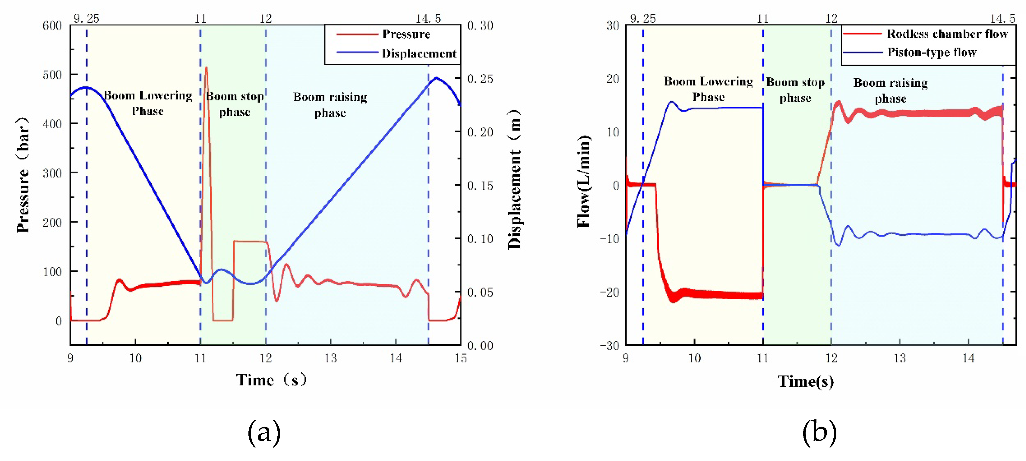
Figure 11(a) shows a representative plunger motion cycle during boom lowering. At 4.54 s, the plunger enters the suction stroke: the high-pressure valve opens, the low-pressure valve closes, and the flow peaks at 20 L/min. With motor displacement fractions of 0.6, 0.8, and 1.0, the high-pressure valve closes at 4.552 s, 4.556 s, and 4.558 s, respectively. Since no energy recovery occurs in this mode, all fluid in the plunger chamber returns to the reservoir during the discharge stroke. The corresponding lowering speeds (Figure 11b) are 0.12, 0.11, and 0.089 m/s.
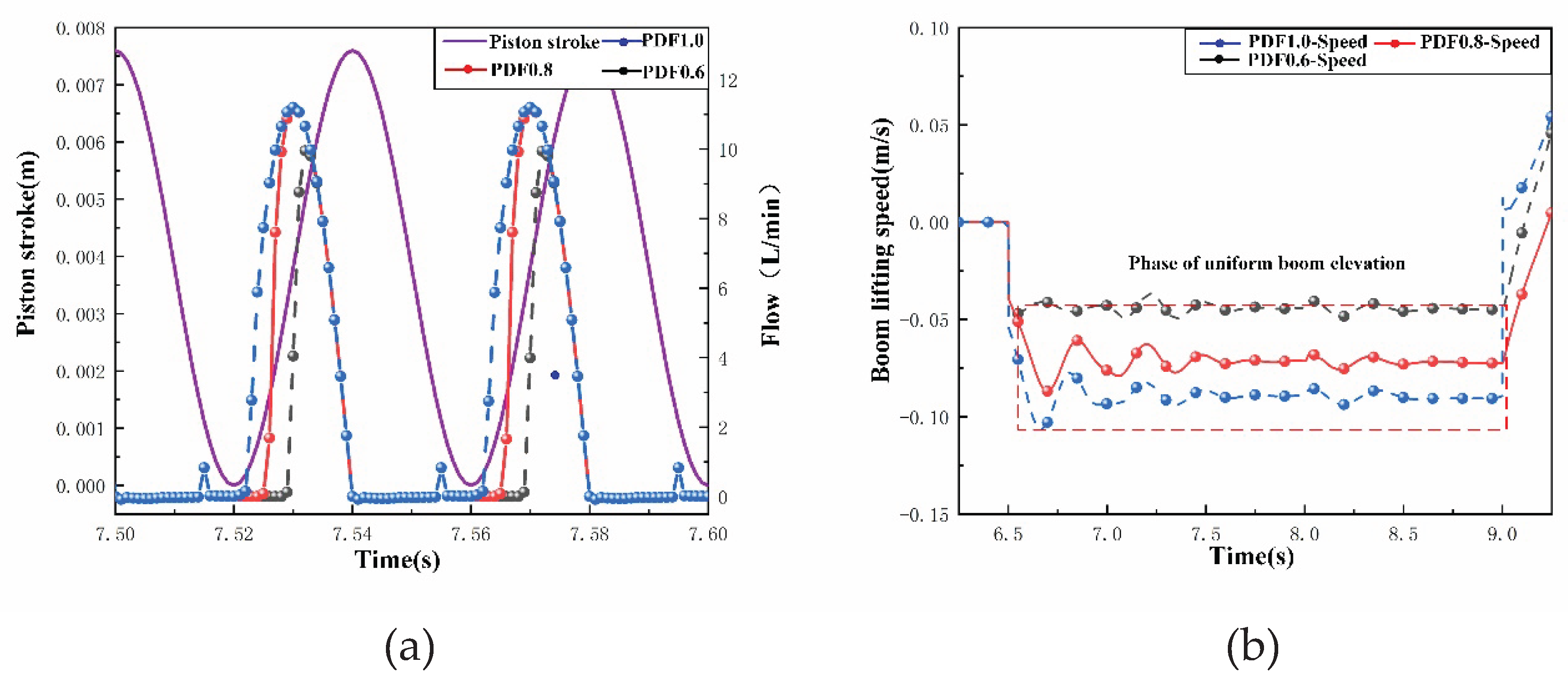
During lifting, the boom speed is regulated by the pump displacement fraction. Figure 12(a) shows that when the coefficient is 1.0, the entire discharge stroke (7.560–7.580 s) delivers fluid to the boom cylinder. At coefficients of 0.8 and 0.6, the effective discharge intervals are 7.565–7.580 s and 7.560–7.570 s, respectively. Accordingly, the lifting speed (Figure 12b) increases with the coefficient, giving 0.04, 0.072, and 0.09 m/s, respectively.
Figure 11.
Flow Rate and Boom Operating Characteristics During the Lowering Phase for Different Motor Displacement Fractions in the Plunger Chamber: (a) flow rate in the plunger chamber; (b) Boom lowering speed.
Figure 11.
Flow Rate and Boom Operating Characteristics During the Lowering Phase for Different Motor Displacement Fractions in the Plunger Chamber: (a) flow rate in the plunger chamber; (b) Boom lowering speed.
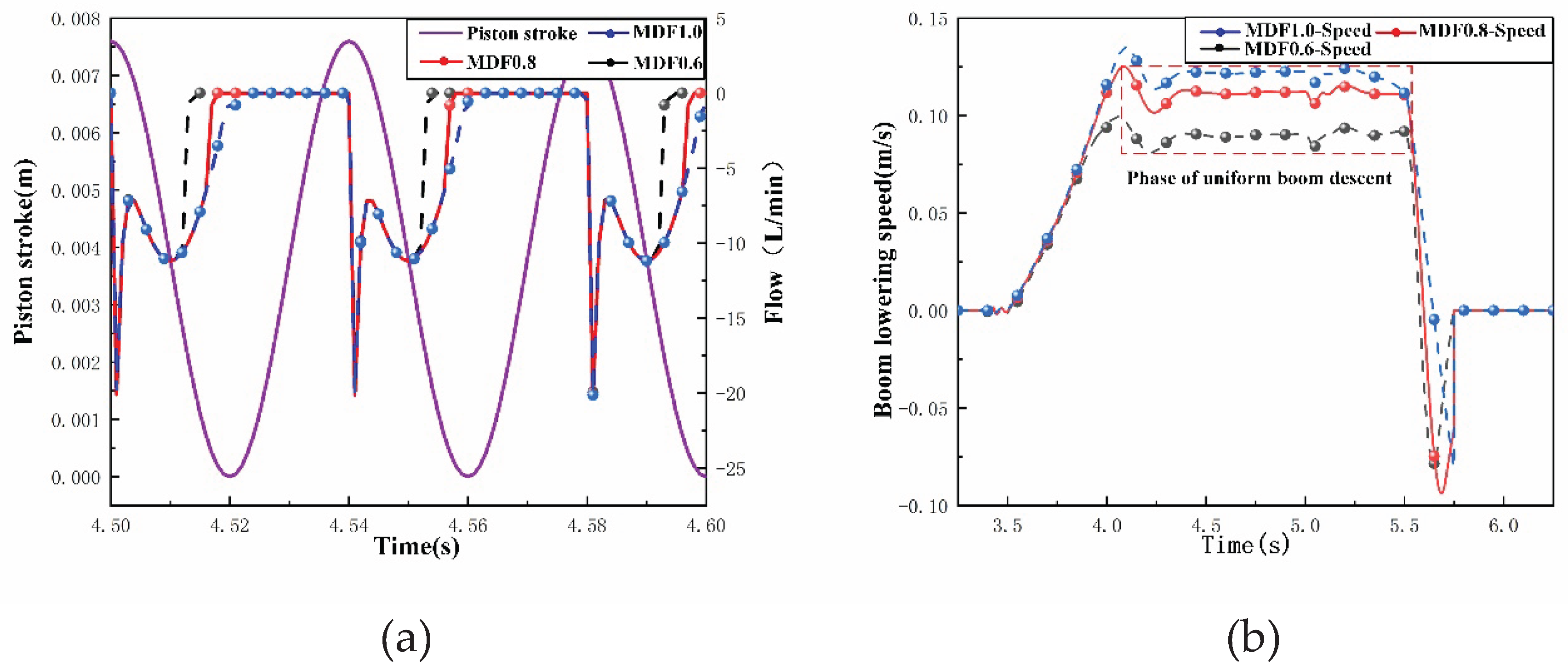
Figure 12.
Flow Rate and Boom Operating Characteristics During the Lifting Phase for Different Pump Displacement Fractions in the Plunger Chamber: (a) Plunger displacement and flow rate in the plunger chamber; (b) Boom lifting speed.
Figure 12.
Flow Rate and Boom Operating Characteristics During the Lifting Phase for Different Pump Displacement Fractions in the Plunger Chamber: (a) Plunger displacement and flow rate in the plunger chamber; (b) Boom lifting speed.
Variations in the load pressure during different stages of boom lifting induce corresponding fluctuations in the plunger chamber pressure (Figure 13a). During the initial, middle, and final stages of boom lifting—specifically when the plunger is in the discharge phase—the pressures in the plunger chamber are 96 bar, 83 bar, and 60 bar, respectively. Similarly, variations in the load pressure during the different stages of boom lowering cause fluctuations in the plunger chamber pressure (Figure 13b). During the initial, middle, and final stages of boom lowering, when the plunger is in the discharge phase, the corresponding plunger chamber pressures are 59 bar, 65 bar, and 78 bar, respectively.
Figure 14 shows the torque characteristics. During lowering, high-pressure oil from the rodless chamber enters the ER port and acts on the plunger during the intake stroke, generating a cam torque in the rotation direction. The DERDP thus operates in motor mode, delivering 10 N·m to the electric motor. Since energy recovery is inactive, this mechanical power is dissipated as heat through the braking resistor. During lifting with a pump displacement fraction of 0.8, the DERDP requires 15 N·m from the motor.
During lowering, the DERDP operates in motor mode. The boom’s gravitational potential energy is converted into hydraulic power, which drives the DERDP and delivers mechanical power to the motor shaft via the common shaft. To maintain speed, the variable-frequency drive dissipates this regenerative power as heat through its braking resistor. Figure 15(a) shows the energy flow during the lifting phase. Since the accumulator was not charged during the preceding lowering phase, the motor is the sole energy source, supplying 5,413 J. The DERDP converts this into 4,622 J of hydraulic energy (82% efficiency), of which 4,462 J reaches the boom cylinder. The cylinder then outputs 4,216 J of mechanical work. The accumulator contributes no energy in this cycle. As shown in Figure 15(b), the total energy loss during the boom lifting phase is 1,197 J. Of this total, pump losses account for 791 J (66.1%), throttling losses for 160 J (13.4%), backpressure losses for 130 J (10.8%), and hydraulic cylinder losses for 116 J (9.7%).
4.2. Operational and Energy Efficiency Characteristics Under Energy Recovery Conditions
Load pressure during boom energy recovery significantly affects recovery efficiency, system response, and stability. During boom lowering, boom gravitational potential energy is recovered to charge the accumulator. The torque coupling relationship within the DERDP can be expressed as:
where is the torque contributed by the energy recovery source (boom), is the motor torque, and is the load torque required to charge the accumulator. If the plunger chamber pressure is excessively high, the recovery source provides a torque such that and , causing the excess energy to be dissipated as heat through the braking resistor of the variable-frequency drive. Conversely, if the plunger chamber pressure is too low, and , requiring the motor to supplement the energy for charging the accumulator—an additional energy conversion step that reduces overall efficiency. Optimal recovery efficiency is achieved when . During boom lifting, the stored energy in the accumulator is released to assist in driving the boom via the DERDP. The torque coupling relationship is:
where denotes the load torque required for boom lifting. When ,the motor provides auxiliary torque to compensate for the torque deficit. When , surplus hydraulic energy is consumed by the braking resistor, resulting in unnecessary energy loss. To comprehensively analyze the system energy recovery performance under varying loads, Simulation tests were conducted under three load conditions (no-load 0 kg, light-load 50 kg, full-load 80 kg) with a fixed accumulator pressure of 80 bar and cylinder stroke of 0.2 m.
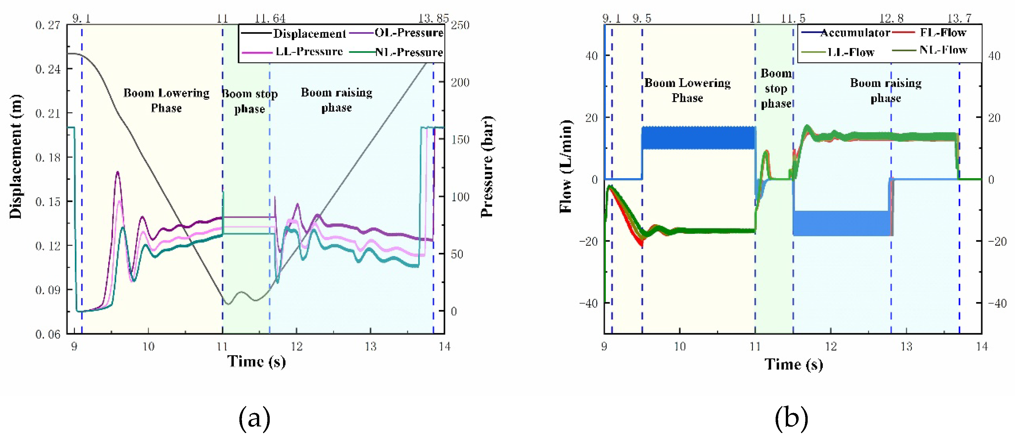
During the boom lowering phase (9.1–11 s), the initial pressure in the rodless chamber is 46 bar, 50 bar, and 64 bar under no-load, light-load, and full-load conditions, respectively, rising to 66 bar, 72 bar, and 80 bar by the end of the lowering phase; the lowering speed remains essentially consistent across all three conditions. Oil from the rodless chamber of the boom cylinder flows into the ER port of the DERDP at 16.8 L/min, and a portion of the oil entering the pump is delivered to the accumulator via the P port at 12.5 L/min. During the boom lifting phase (11.69–13.85 s), the accumulator initially discharges oil at 15.2 L/min to assist the motor in driving the DERDP. After 12.8 s, the accumulator is depleted, and the DERDP is driven solely by the motor, supplying oil to the boom cylinder at 13.2 L/min. Under no-load, light-load, and full-load conditions, the rodless chamber pressure decreases from 69 bar to 40 bar, from 76 bar to 49 bar, and from 92 bar to 65 bar, respectively.
Figure 16.
Pressure and Flow Characteristics of the Boom Cylinder Under Different Load Conditions: (a) Boom cylinder stroke and pressure; (b) Accumulator and rodless chamber flow.
Figure 16.
Pressure and Flow Characteristics of the Boom Cylinder Under Different Load Conditions: (a) Boom cylinder stroke and pressure; (b) Accumulator and rodless chamber flow.
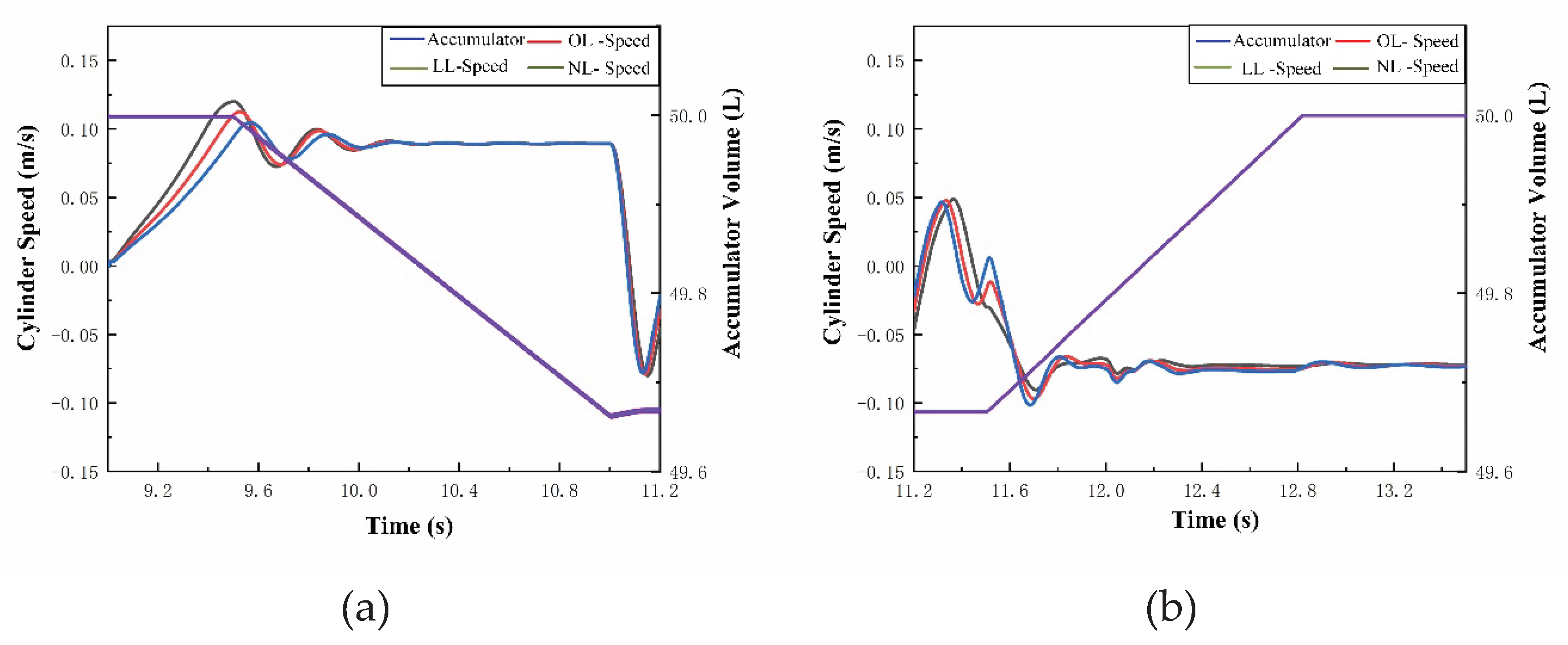
During the lowering phase, the rodless chamber of the boom cylinder is connected to the ER port and the pump discharge port is connected to the accumulator. With both pump and motor displacement fractions set to 0.8, boom lowering speed is 0.09 m/s under all three load conditions, and the gas volume in the accumulator is compressed from 50 L to 49.663 L. During the boom lifting phase, the initial stage is powered by high-pressure fluid from the accumulator flowing into the DERDP through the ER port, enabling reuse of the recovered energy. Boom lifting speed is 0.07 m/s under all three load conditions. In the middle stage of the lifting phase, stored hydraulic energy in the accumulator is fully discharged and its volume returns to the initial 50 L. In the final stage, energy required for boom lifting is supplied entirely by the motor.
Figure 17.
Cylinder speed and accumulator volume characteristics under different load conditions: (a) Boom lowering phase; (b) Boom lifting phase.
Figure 17.
Cylinder speed and accumulator volume characteristics under different load conditions: (a) Boom lowering phase; (b) Boom lifting phase.
Plunger chamber pressure characteristics under energy-recovery mode are analysed for both boom-lowering and boom-lifting processes (Figure 18), with pump mode and motor-mode displacement fractions fixed at 0.8. During boom lowering (Figure 18 a-c), the plunger draws fluid from the boom cylinder in the suction stroke and pressurises the accumulator in the discharge stroke. Suction-side pressure rises noticeably across early, intermediate and final lowering stages, reaching 44 bar, 49 bar and 63 bar (no-load, light-load and full-load, respectively) at the early stage; 51 bar, 58 bar and 67 bar at the intermediate stage; and 60 bar, 67 bar and 74 bar at the final stage. This trend originates from the continuously increasing gravitational moment arm as the boom descends. By comparison, discharge side pressure remains nearly constant at 83 bar under all loads, which is dictated by the 80 bar accumulator precharge pressure. Since suction-side pressure is persistently lower than discharge-side pressure and this pressure differential shrinks at higher payloads, the electric motor must provide supplementary torque to maintain stable accumulator charging.
Unlike the monotonic pressure rise observed during lowering, the boom-lifting phase exhibits a clear two stage transition triggered by accumulator depletion (Figure 18 d-f). In the initial lifting stage, the pre-charged accumulator delivers fluid at 78 bar via the energy-recovery port during suction. The plunger discharge stroke supplies fluid to the boom cylinder at 54 bar, 62 bar and 74 bar for no-load, light-load and full-load scenarios, respectively. After the accumulator is fully discharged, the suction-side fluid source switches completely to the low-pressure tank. Consequently, discharge-side pressure falls to 50 bar, 57 bar and 69 bar in the intermediate lifting stage and further decreases to 39 bar, 48 bar and 63 bar at the final stage as the boom approaches its upper limit and the load moment arm shortens. This sequential shift from accumulator assisted actuation to motor-only drive embodies the core operating principle of the DERDP direct energy recovery architecture.
The torque and energy characteristics of the DERDP system are presented in Figure 19 for the three load conditions. During the boom lowering phase (Figure 19b), the motor torque decreases progressively from initial values of 4.5 N·m, 6.5 N·m, and 8.5 N·m to final values of 1.5 N·m, 3.5 N·m, and 5.5 N·m under no-load, light-load, and full-load conditions, respectively. This reduction reflects the diminishing gravitational driving force as the boom approaches its lowest position. During the subsequent lifting phase, Figure 19(a) shows that the accumulator delivers a consistent 2,756 J of energy per cycle across all load conditions, while the motor contributes 2317 J, 2554 J, and 2903 J, respectively, indicating that the motor must compensate for the energy shortfall that increases with load. The accumulator supplies high-pressure fluid to the ER port between 11.64 s and 12.83 s. During this interval, the motor torque is substantially reduced to only 0.6 N·m, 1.6 N·m, and 3.5 N·m under the three loads, confirming the effective assist from the recovered energy. Once the accumulator is depleted after 12.83 s, the motor torque rises sharply to 10.5 N·m, 11.6 N·m, and 13.2 N·m, respectively, as the system reverts to motor-only drive.
4. Discussion
4.1. Mechanistic Interpretation of Energy Recovery Efficiency
The energy recovery efficiency of 50%–60% achieved by the DERDP-based system is governed by the instantaneous torque balance on the common shaft. During boom lowering, the balance is expressed as ; during lifting, it becomes . Optimal efficiency is obtained when the recovered torque matches the required charging or lifting torque, minimizing motor assistance or resistive dissipation.
The pump-related losses, which account for 66.1% of the total system loss in non-recovery mode (791 J out of 1,197 J), represent the dominant dissipation source. These losses arise from high-pressure fluid compression and internal leakage within the plunger chambers during the discharge stroke—characteristics inherent to the digital displacement principle. By eliminating valve throttling losses, the DERDP shifts the efficiency bottleneck from the control valve to the pump itself, thereby creating the fundamental opportunity for energy recovery.
The plunger-chamber pressure variation under different load conditions (Figure 18) reveals an important passive load-adaptation feature. As the boom descends, the lengthening gravitational moment arm raises the rodless chamber pressure from 44 bar to 74 bar, increasing the recovered torque at the ER port and consequently reducing the motor torque required for accumulator charging. This mechanical coupling enables load-adaptive energy capture without active control intervention.
4.2. Comparison with Previous Work and Engineering Implications
The 50%–60% recovery-reuse efficiency achieved in this study aligns closely with the 53%–58% fuel reduction projected by Macpherson et al. for a combined digital hydraulic drive and boom energy recovery system on an 18-tonne excavator[18]. However, unlike Macpherson’s scheme, which employs separate pump and motor units for recovery and actuation, the DERDP integrates both functions within a single unit. This integration reduces component count and system complexity while maintaining comparable efficiency—suggesting that the integration of pumping and recovery functions does not incur a significant efficiency penalty.
A key trade-off should be acknowledged: the DERDP sacrifices some control flexibility (since pump and motor operations are coupled through the common shaft) in exchange for significantly lower system cost, weight, and potential failure points. For cost-sensitive and space-constrained construction machinery applications, this trade-off is favorable and enhances the practical viability of the DERDP concept.
Compared with the separated digital-displacement pump-motor architecture reported by Lagarde et al. [17], which achieves a full-cycle system efficiency of 54.6 %, the DERDP approach addresses not only pump-valve losses but also the broader challenge of gravitational energy management. The 2,834 J of energy harvested per lowering cycle represents a meaningful contribution to the overall system energy balance, particularly for excavators operating in repetitive loading cycles where boom lowering accounts for a substantial portion of the duty cycle.
4.3. Limitations and Future Directions
While the DERDP concept has been validated through simulation and hardware-in-the-loop experiments, its performance boundaries under real-world excavator operations remain to be fully characterized. The present study focused on the boom circuit under idealized loading conditions; extending the integrated pumping-recovery architecture to multi-actuator energy management—where boom-lowering energy is directly reused for arm or bucket operations—represents a promising direction for further enhancing machine-level efficiency.
A key area for future investigation concerns the interaction between the accumulator and the DERDP under varying load conditions. The pre-charge pressure was fixed at 80 bar in this study, yet the optimal pre-charge is likely load-dependent. Parametric studies are therefore needed to determine optimal accumulator sizing and pre-charge configurations, with variable-charge strategies meriting particular attention.
Beyond hardware optimization, the control strategy currently employs fixed displacement fractions. Developing a real-time adaptive controller—for instance, one based on model predictive control—could dynamically adjust these fractions according to instantaneous load pressure and accumulator charge state, potentially improving recovery efficiency beyond the current 50%–60% level.Addressing these points will advance the DERDP from a validated concept toward a field-ready solution for energy-efficient construction machinery.
5. Conclusions
This study proposed a pump-controlled digital hydraulic drive system for excavator booms based on a Direct Energy Recovery Digital Pump (DERDP) that integrates hydraulic pumping and gravitational potential energy recovery within a single unit. Using a validated AMESim simulation model, the system’s operational characteristics and energy efficiency were systematically investigated under both non-recovery and energy-recovery conditions. The main conclusions are summarized as follows.
In non-recovery mode, the DERDP system consumes 5,413 J of motor input energy per lifting cycle. Pump-related losses of 791 J account for 66.1% of the total system loss (1,197 J). By eliminating throttling losses inherent to valve-controlled circuits, the pump-controlled digital hydraulic architecture shifts the efficiency bottleneck from the control valve to the pump itself.
In energy-recovery mode, the DERDP harvests 2,834 J of gravitational potential energy per lowering cycle, independent of payload, and stores it directly in the accumulator. The plunger-chamber pressure varies from 44 bar to 74 bar during boom descent, enabling passive load adaptation through the mechanical advantage of the lengthening moment arm.
The recovered energy supplies 2,756 J per lifting cycle, reducing motor energy consumption from 2,903 J (full-load) to 2,317 J (no-load). The overall energy recovery-reuse efficiency reaches 50%–60%, which is comparable to or exceeds values reported for separate pump-motor configurations (53%–58%), demonstrating that the integration of pumping and recovery functions does not incur a significant efficiency penalty.
The DERDP architecture simplifies the hydraulic circuit by eliminating a separate motor unit for energy recovery, reducing component count, system complexity, and potential failure points, while maintaining competitive efficiency. This makes the DERDP a practical and cost-effective solution for improving the energy efficiency of excavator boom operations.
Author Contributions
Daling Yue: Writing – review & editing, Validation, Supervision, Resources, Project administration, Methodology, Conceptualization. Shaomou Liu: Writing – original draft, Visualization, Software, Methodology. Yongheng Si: Writing – review & editing, Data curation. Liejiang Wei: Validation, Formal analysis, Resources, Project administration, Methodology. Zengguang Liu: Validation, Formal analysis, Resources, Methodology. Hongfei Gao: Investigation, Data curation, Formal analysis.
Funding
This work was supported by National Key Research and Development Program of China (No. 2023YFB3406704); Major Cultivation Project of University Scientific Research Innovation Platform, Gansu Provincial Department of Education (No. 2024CXPT-09).
Data Availability Statement
The data that support the findings of this study are available from the corresponding author upon reasonable request.
Conflicts of Interest
The authors declare that they have no known competing financial interests or personal relationships that could have appeared to influence the work reported in this paper.
References
- Yan, X.; Chen, B.; Zhang, D. An energy-saving method to reduce the installed power of hydraulic press machines. J. Clean. Prod. 2019, 233, 538–545. [CrossRef]
- Liu, X.; Chen, Z. A hydraulic system energy analysis method for energy-saving design of crane lifting mechanism. J. Phys. Conf. Ser. 2025, 3068, 012131. [CrossRef]
- Lin, T.; Chen, Q.; Ren, H. Review of boom potential energy regeneration technology for hydraulic construction machinery. Renew. Sustain. Energy Rev. 2017, 79, 358–371. [CrossRef]
- Vukovic, M.; Leifeld, R.; Murrenhoff, H. Reducing fuel consumption in hydraulic excavators—A comprehensive analysis. Energies 2017, 10, 687. [CrossRef]
- Linjama, M. Digital fluid power—state of the art. In Proceedings of the 12th Scandinavian International Conference on Fluid Power (SICFP), Tampere, Finland, 2011.
- Eriksson, B.; Palmberg, J.O. Individual metering fluid power systems: challenges and opportunities. Proc. Inst. Mech. Eng. Part I J. Syst. Control. Eng. 2011, 225, 196–211. [CrossRef]
- Heybroek, K. On energy efficient mobile hydraulic systems with focus on linear actuation. Ph.D. Thesis, Linköping University, Sweden, 2017.
- Dumnov, D.; Caldwell, N. A cylinder enabling algorithm for reduction in low frequency pulsation from digital displacement pumps. In Proceedings of the ASME/BATH 2022 Symposium on Fluid Power and Motion Control, Longboat Key, FL, USA, 7-9 October 2022. [CrossRef]
- Johansen, P.; Roemer, D.B.; Andersen, T.O.; Pedersen, H.C. Discrete linear time invariant analysis of digital fluid power pump flow control. J. Dyn. Syst. Meas. Control. 2017, 139, 101007. [CrossRef]
- Linjama, M.; Huova, M.; Karhu, O. Energy-efficient motion control of a digital hydraulic joint actuator. In Proceedings of the 9th JFPS International Symposium on Fluid Power, Matsue, Japan, 2014. [CrossRef]
- Murrenhoff, H.; Sgro, S.; Vukovic, M. An overview of energy saving architectures for mobile applications. In Proceedings of the 9th International Fluid Power Conference (IFK), Aachen, Germany, 2014.
- Hutcheson, J.; Abrahams, D.; Green, M. Motion control of a hydraulic cylinder with a digital displacement pump-motor. In Proceedings of the 13th International Fluid Power Conference (IFK), Aachen, Germany, 2022; pp. 705-718.
- Williamson, C.; Manring, N. A more accurate definition of mechanical and volumetric efficiencies for digital displacement® pumps. In Proceedings of the ASME/BATH 2019 Symposium on Fluid Power and Motion Control, Longboat Key, FL, USA, 7-9 October 2019. [CrossRef]
- Pellegri, M.; Green, M.; Macpherson, J.; Mackay, C.; Caldwell, N. Applying a multi-service digital displacement pump to an excavator to reduce valve losses. In Proceedings of the 12th International Fluid Power Conference (IFK), Dresden, Germany, 12-14 October 2020. [CrossRef]
- Green, M.; Macpherson, J.; Caldwell, N. DEXTER: the application of a digital displacement® pump to a 16 tonne excavator. In Proceedings of the ASME/BATH 2018 Symposium on Fluid Power and Motion Control, Longboat Key, FL, USA, 7-9 October 2018. [CrossRef]
- Budden, J.J.; Williamson, C. Danfoss digital displacement® excavator: test results and analysis. In Proceedings of the ASME/BATH 2019 Symposium on Fluid Power and Motion Control, Longboat Key, FL, USA, 7-9 October 2019. [CrossRef]
- Lagarde, J.; Green, M.; Dole, A. Danfoss digital displacement & editron: an efficient electro-hydraulic system for mobile applications. In Proceedings of the 12th International Fluid Power Conference (IFK), Aachen, Germany, 2023.
- Macpherson, J.; Williamson, C.; Green, M. Energy efficient excavator hydraulic systems with digital displacement® pump-motors and digital flow distribution. In Proceedings of the Fluid Power Systems Technology, Online, 2020. [CrossRef]
- Darnet, J.; Bideaux, É. State-of-the-art of variable displacement technologies for radial plunger hydraulic machines. In Proceedings of the BATH/ASME 2022 Symposium on Fluid Power and Motion Control, Longboat Key, FL, USA, 7-9 October 2022. [CrossRef]
- Hutcheson, J.; Abrahams, D.; Macpherson, J.; Caldwell, N.J.; Rampen, W. Demonstration of Efficient Energy Recovery Systems Using Digital Displacement® Hydraulics. In Proceedings of the BATH/ASME 2020 Symposium on Fluid Power and Motion Control, Online, 2020. [CrossRef]
- Yue, D.; Gao, H.; Liu, Z. Potential energy recovery and direct reuse system of hydraulic hybrid excavators based on the digital pump. Energies 2023, 16, 5299. [CrossRef]
- Yue, D.; Zuo, X.; Liu, Z. An adaptive control method for the distribution valve of a digital pump. Machines 2023, 11, 148. [CrossRef]
Figure 1.
DERDP configuration and graphic symbols: (a) DERDP Configuration; (b) DERDP Graphic Symbols.
Figure 1.
DERDP configuration and graphic symbols: (a) DERDP Configuration; (b) DERDP Graphic Symbols.
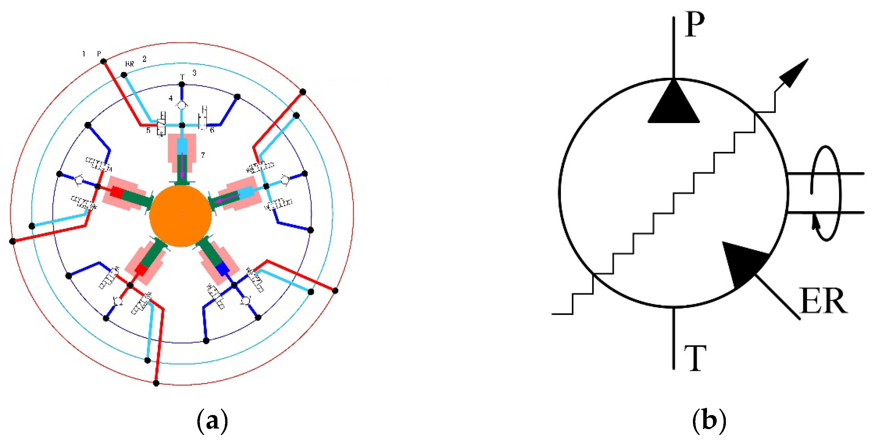
Figure 2.
Single-Plunger Unit Structure and Valve Control Strategy: (a) Single-Plunger Unit Structure and Stroke Phase Definition; (b) Schematic Diagram of the Control Strategy.
Figure 2.
Single-Plunger Unit Structure and Valve Control Strategy: (a) Single-Plunger Unit Structure and Stroke Phase Definition; (b) Schematic Diagram of the Control Strategy.
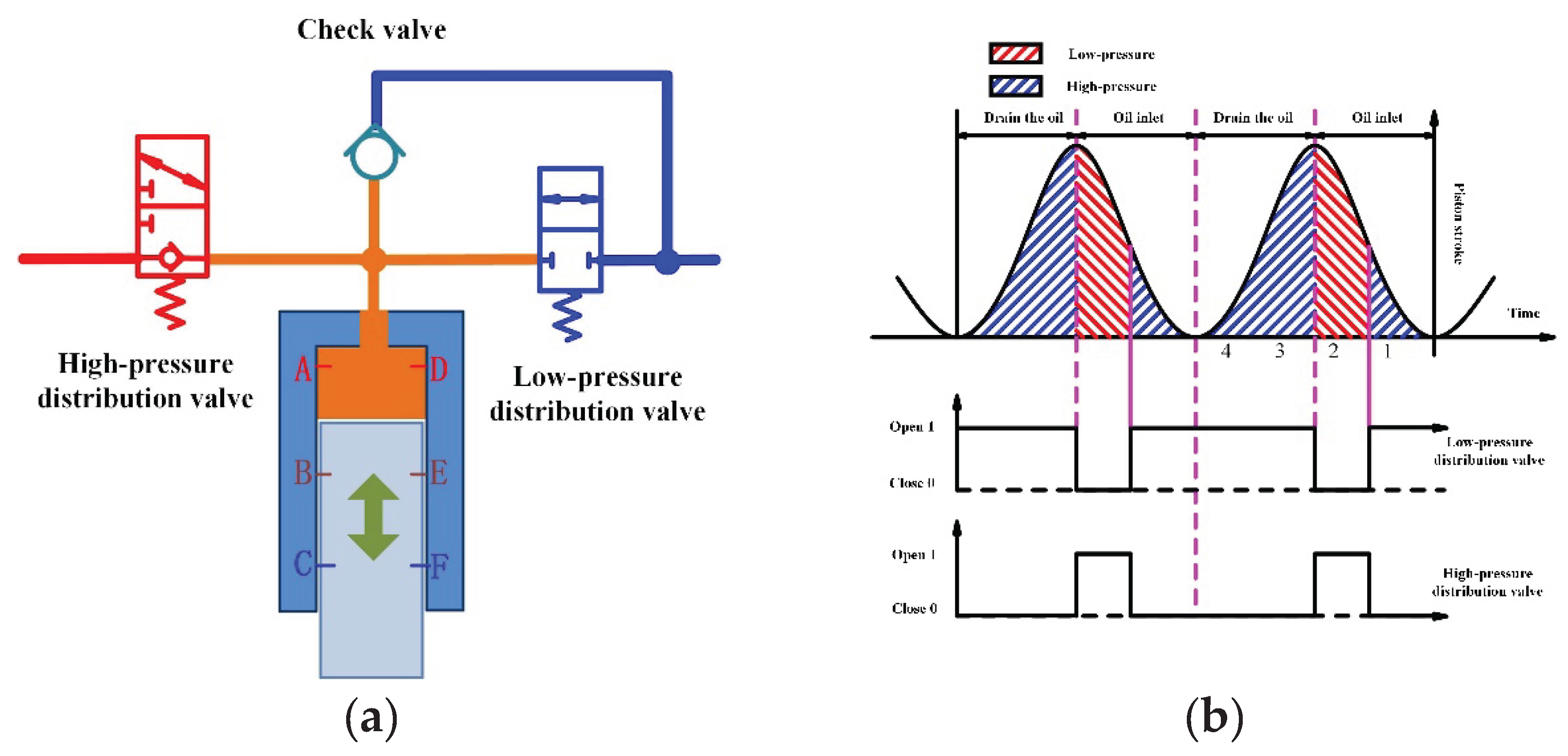
Figure 3.
Schematic Diagram of Different DERDP Modes: (a) Digital Pump Mode; (b) Digital Motor Mode; (c) Energy Recovery Mode.
Figure 3.
Schematic Diagram of Different DERDP Modes: (a) Digital Pump Mode; (b) Digital Motor Mode; (c) Energy Recovery Mode.
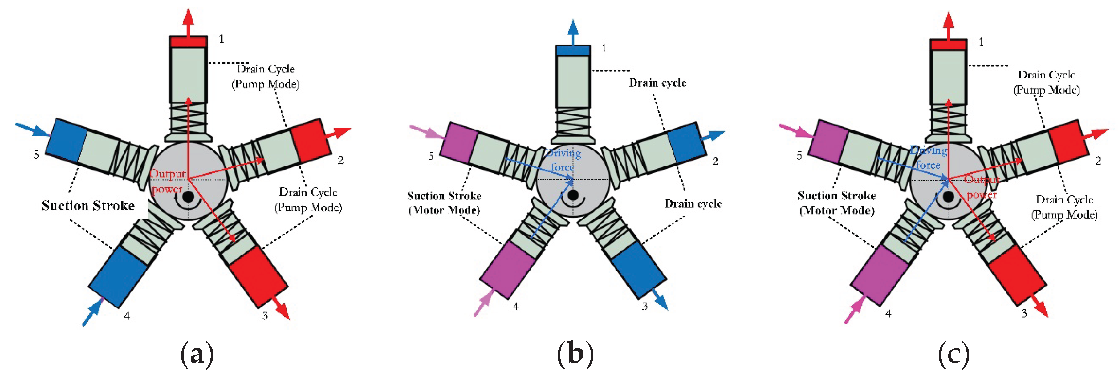
Figure 4.
Schematic Diagram of the Digital Hydraulic Drive System for the Boom.
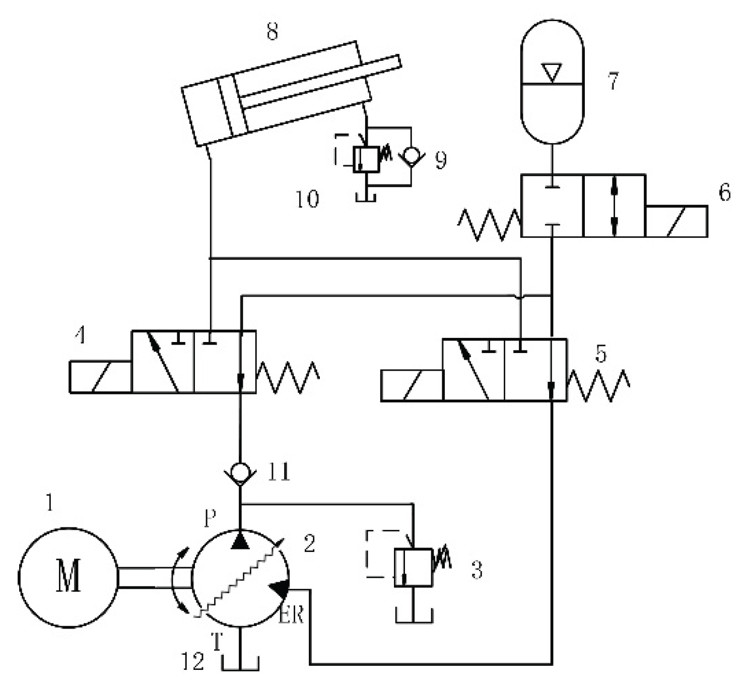
Figure 5.
Schematic Diagram of Boom Operating Modes: (a) Recovery of Boom Potential Energy; (b) Reuse of Recovered Potential Energy.
Figure 5.
Schematic Diagram of Boom Operating Modes: (a) Recovery of Boom Potential Energy; (b) Reuse of Recovered Potential Energy.
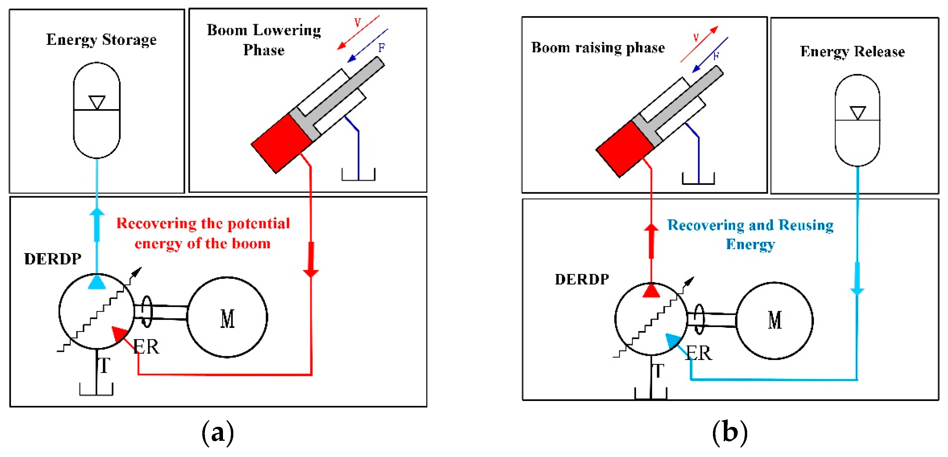
Figure 6.
Simulation Models of the DERDP Single- Plunger Unit and the Overall Boom Digital Hydraulic Drive System: (a) DERDP Single- plunger Model; (b) Simulation model of a digital hydraulic drive system for a boom.
Figure 6.
Simulation Models of the DERDP Single- Plunger Unit and the Overall Boom Digital Hydraulic Drive System: (a) DERDP Single- plunger Model; (b) Simulation model of a digital hydraulic drive system for a boom.
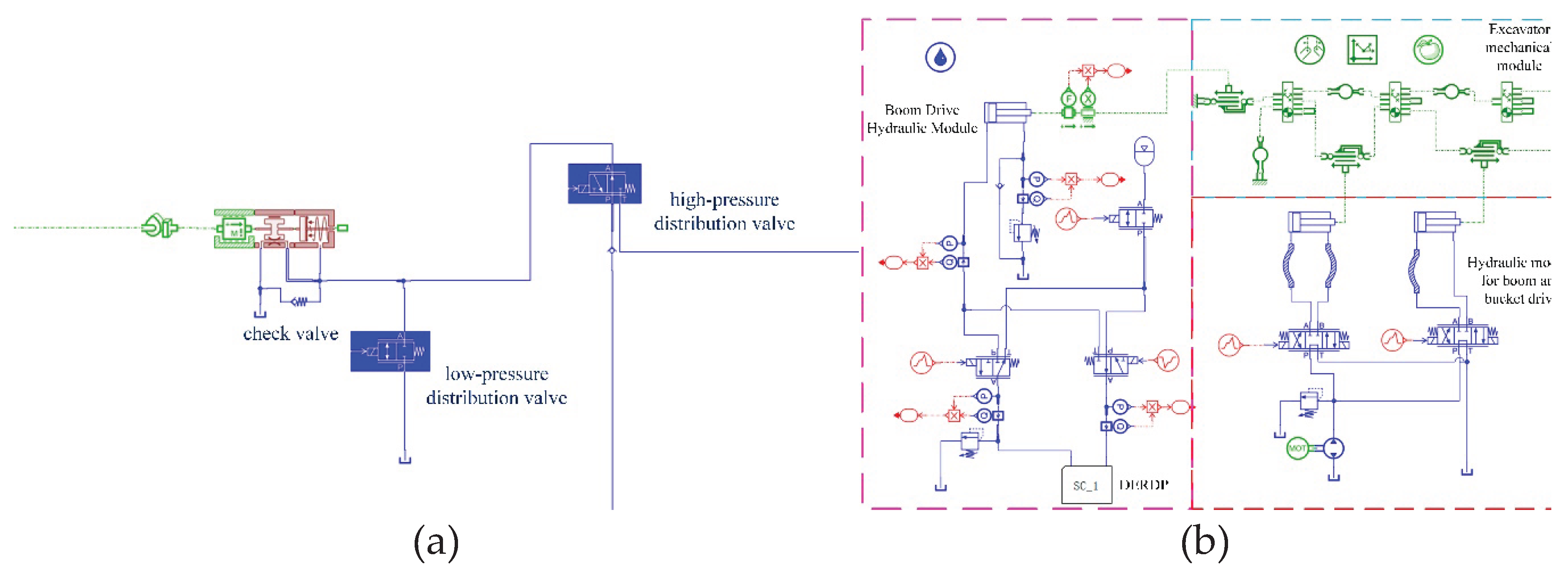
Figure 7.
Working Cycle Diagram of the Excavator Working Mechanism.
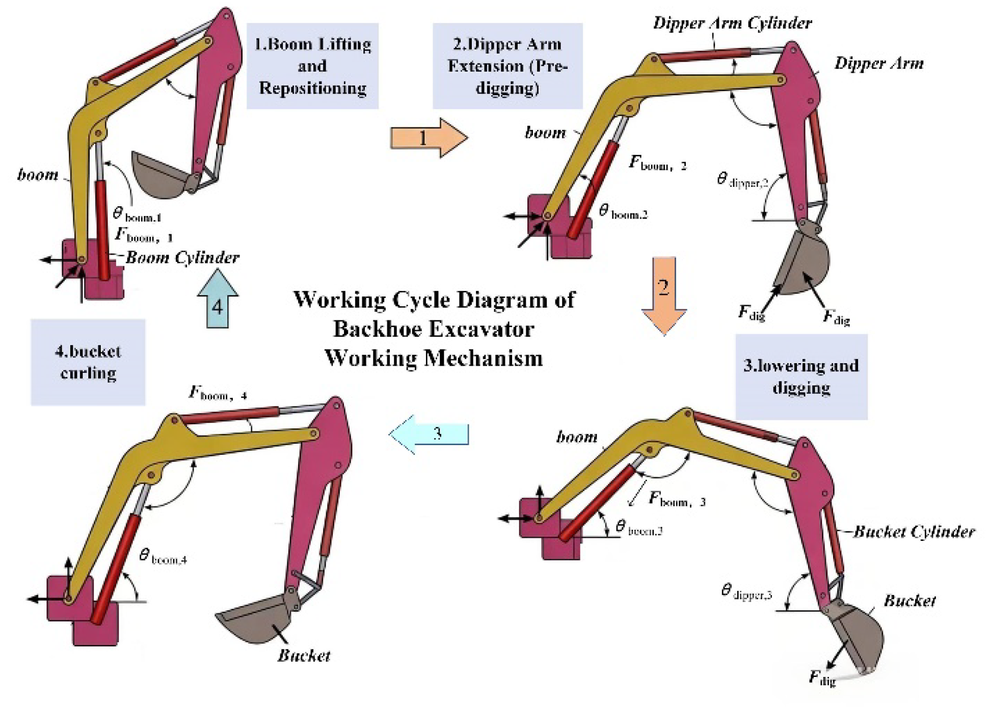
Figure 8.
Experimental system of the digital hydraulic boom drive: (a) System schematic; (b) Test Bench.
Figure 8.
Experimental system of the digital hydraulic boom drive: (a) System schematic; (b) Test Bench.
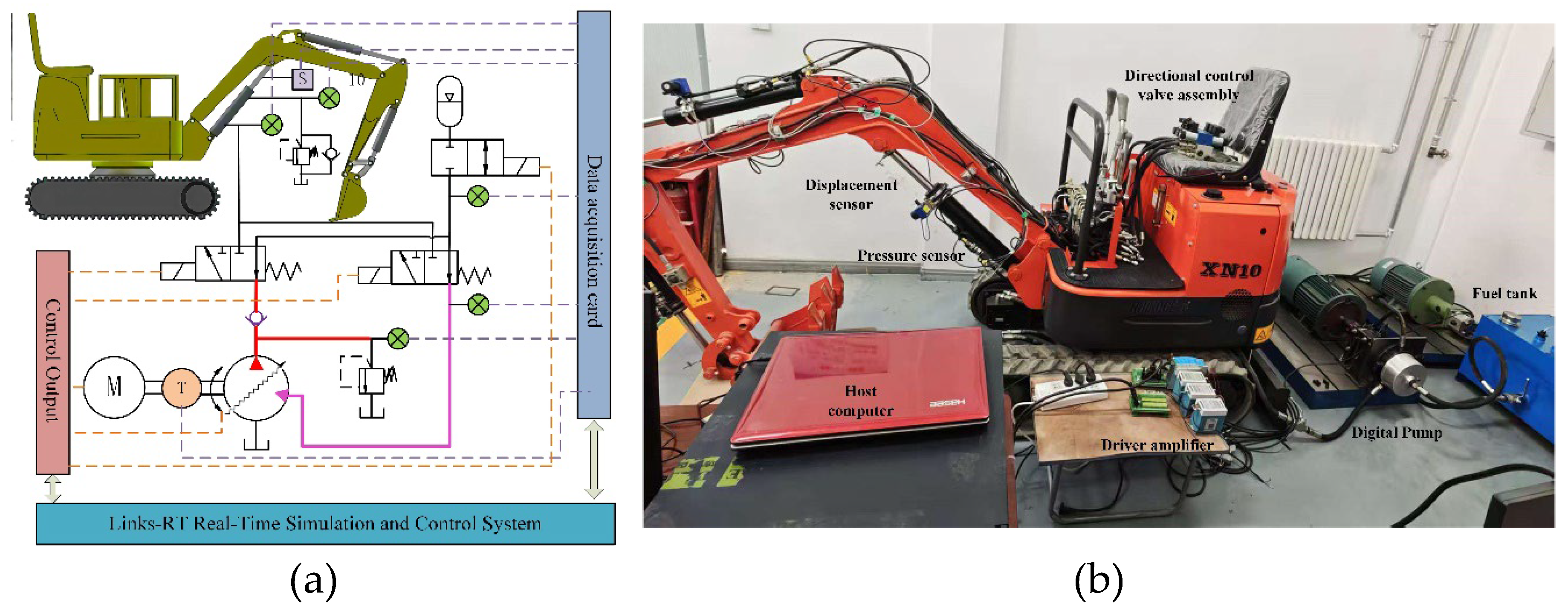
Figure 9.
Comparison of Simulated and Experimental Curves for Boom Cylinder Pressure and Displacement: (a) Displacement during the boom lowering phase; (b) Pressure in the rodless chamber during the boom lowering phase; (c) Displacement during the boom lifting phase; (d) Pressure in the rodless chamber during the boom lifting phase.
Figure 9.
Comparison of Simulated and Experimental Curves for Boom Cylinder Pressure and Displacement: (a) Displacement during the boom lowering phase; (b) Pressure in the rodless chamber during the boom lowering phase; (c) Displacement during the boom lifting phase; (d) Pressure in the rodless chamber during the boom lifting phase.
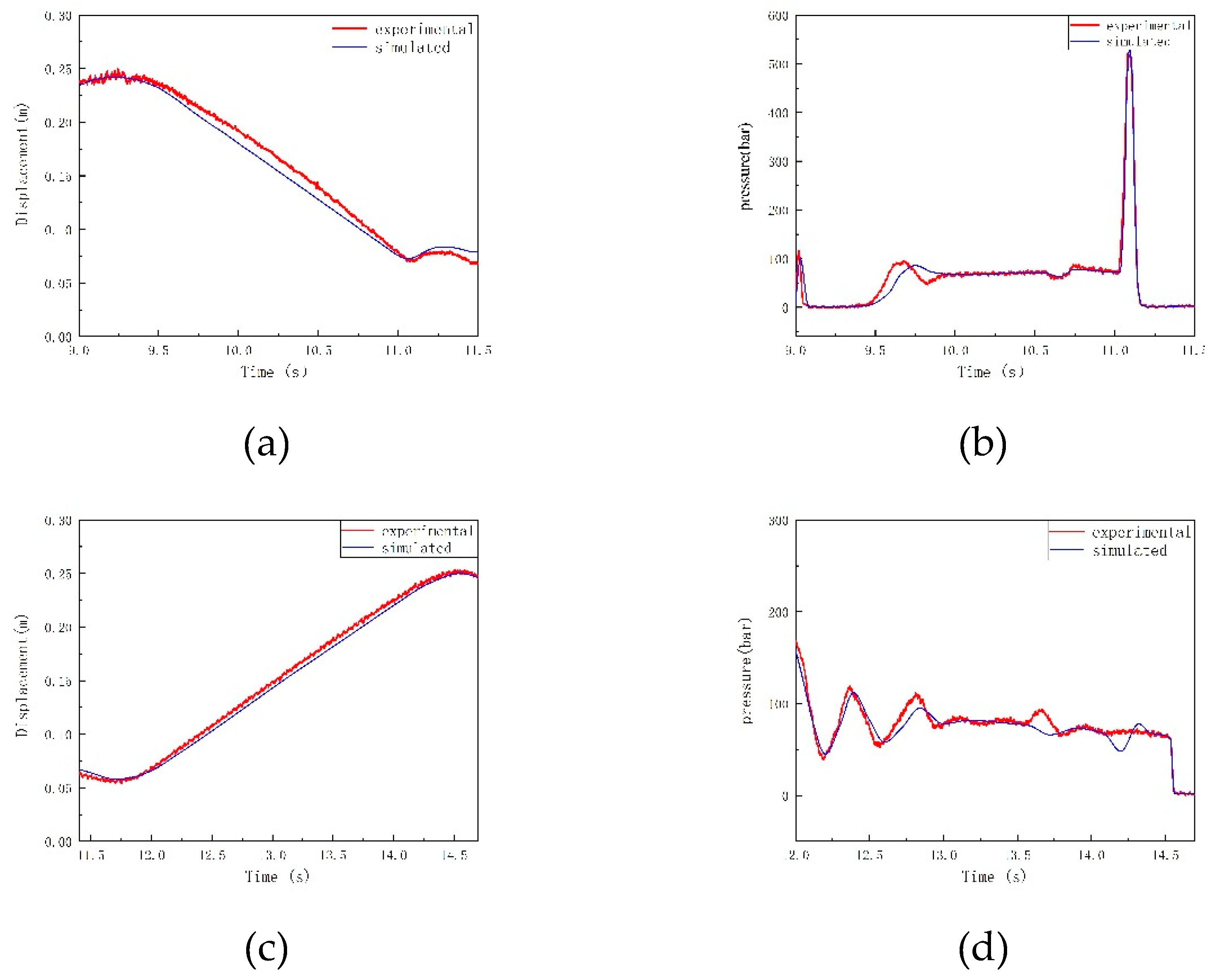
Figure 13.
Pressure Characteristics in the Plunger Chamber During Different Stages of Boom Lifting and Lowering: (a) Plunger chamber pressure at different stages of boom lifting; (b) Plunger chamber pressure at different stages of boom lowering.
Figure 13.
Pressure Characteristics in the Plunger Chamber During Different Stages of Boom Lifting and Lowering: (a) Plunger chamber pressure at different stages of boom lifting; (b) Plunger chamber pressure at different stages of boom lowering.
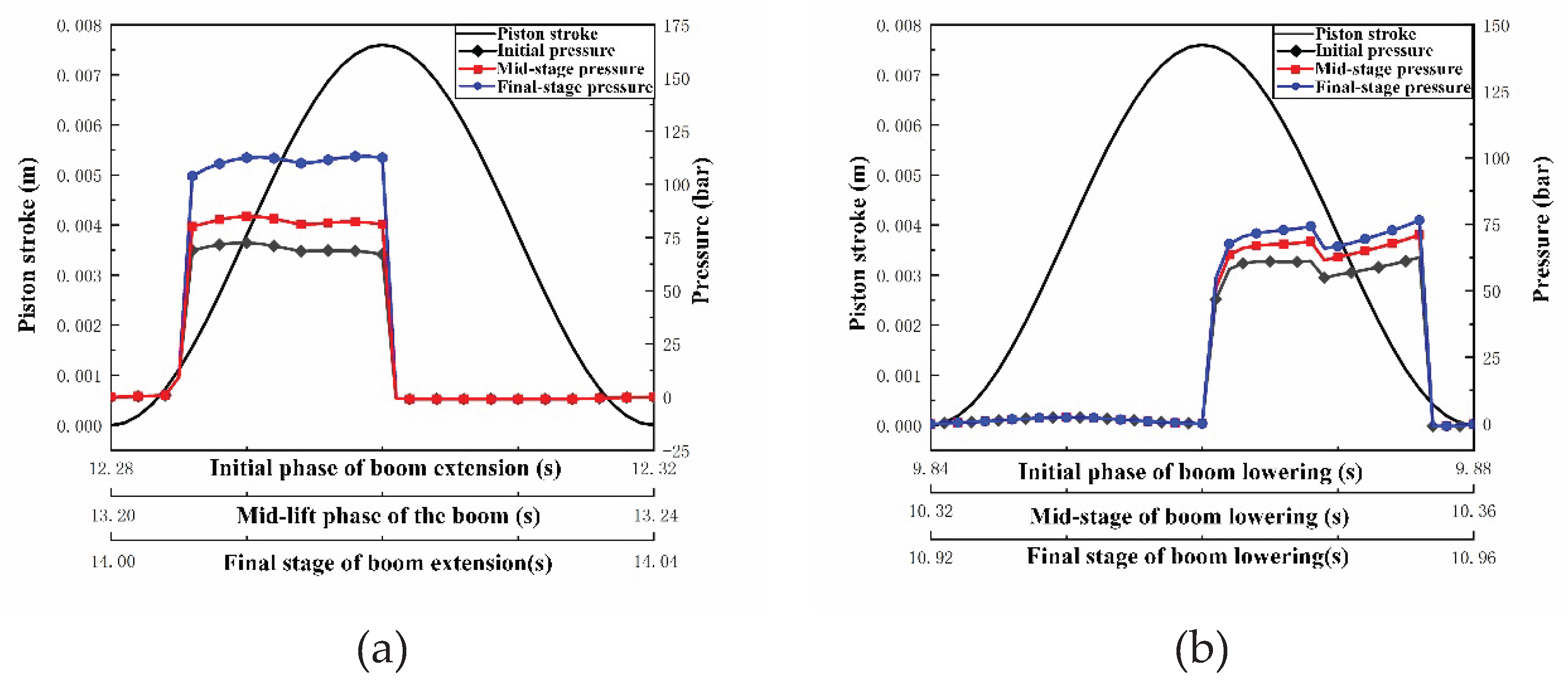
Figure 14.
Torque Output Characteristics of the Motor During Boom Lift and Lowering Phases.
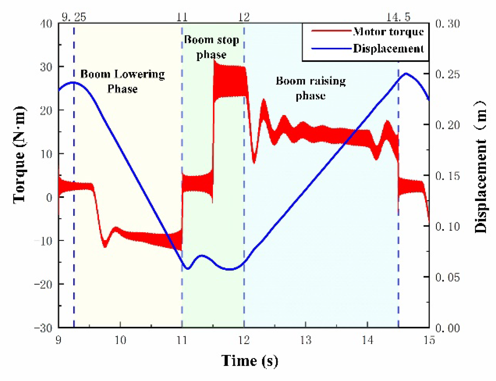
Figure 15.
Energy Loss and Proportion of Energy Loss During the Boom Lifting Phase of a Digital Hydraulic Drive System: (a) Energy consumption during the lifting phase; (b) Percentage of energy loss in each section of the lifting phase.
Figure 15.
Energy Loss and Proportion of Energy Loss During the Boom Lifting Phase of a Digital Hydraulic Drive System: (a) Energy consumption during the lifting phase; (b) Percentage of energy loss in each section of the lifting phase.
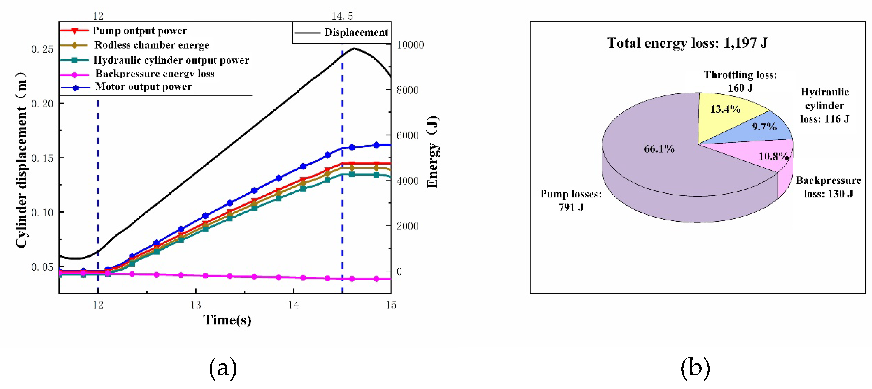
Figure 18.
Pressure characteristics in the plunger chamber during different phases of boom movement: (a) Pressure in the plunger chamber during the early stage of lowering; (b) Pressure in the plunger chamber during the mid-stage of lowering; (c) Pressure in the plunger chamber during the final stage of lowering; (d) Pressure in the plunger chamber during the early stage of lifting; (e) Pressure in the plunger chamber during the mid-stage of lifting; (f) Pressure in the plunger chamber during the final stage of lifting.
Figure 18.
Pressure characteristics in the plunger chamber during different phases of boom movement: (a) Pressure in the plunger chamber during the early stage of lowering; (b) Pressure in the plunger chamber during the mid-stage of lowering; (c) Pressure in the plunger chamber during the final stage of lowering; (d) Pressure in the plunger chamber during the early stage of lifting; (e) Pressure in the plunger chamber during the mid-stage of lifting; (f) Pressure in the plunger chamber during the final stage of lifting.
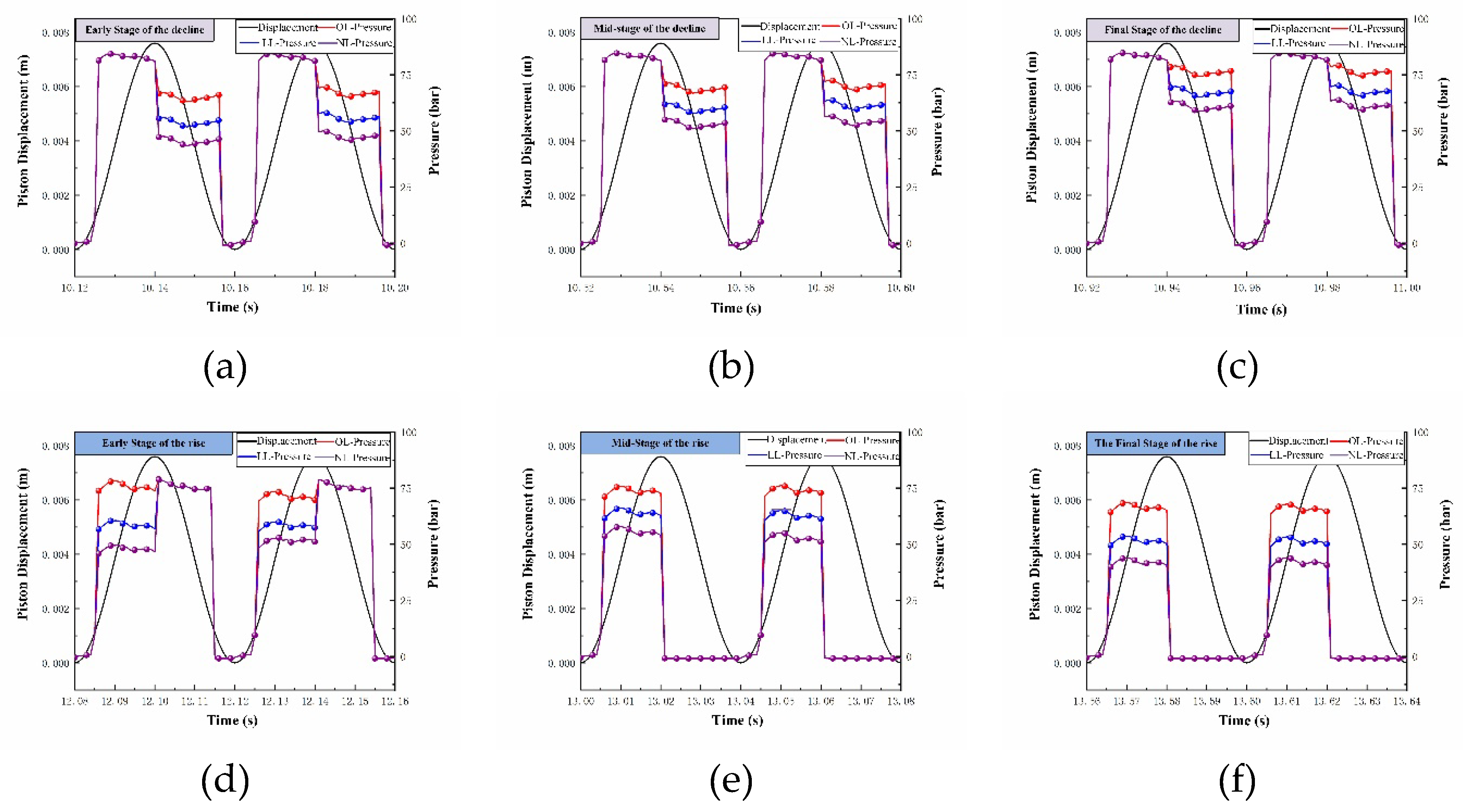
Figure 19.
Energy characteristics of the accumulator and motor under different load conditions: (a) Energy supplied by the accumulator and motor during the lifting phase; (b) Motor torque.
Figure 19.
Energy characteristics of the accumulator and motor under different load conditions: (a) Energy supplied by the accumulator and motor during the lifting phase; (b) Motor torque.
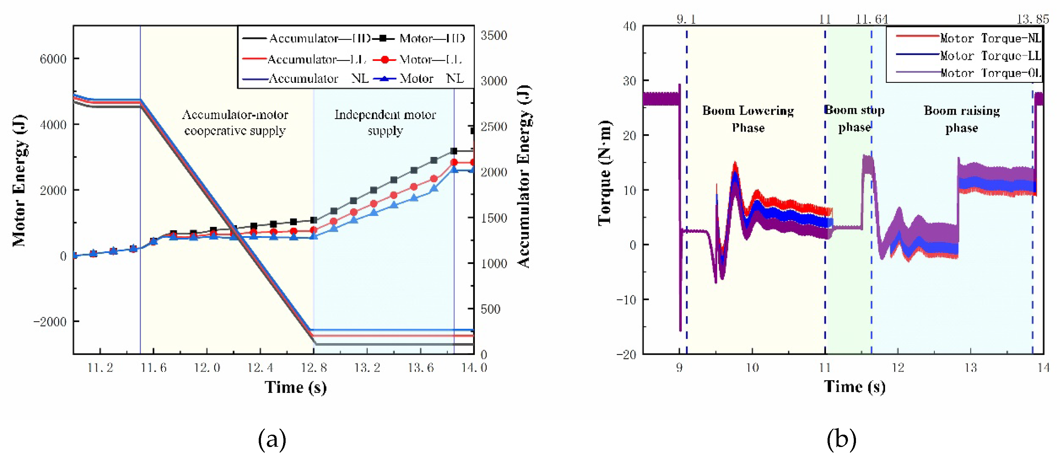

Table 1.
Effective Stroke of the Plunger and Corresponding Operating Conditions in DERDP Pump and Motor Modes.
Table 1.
Effective Stroke of the Plunger and Corresponding Operating Conditions in DERDP Pump and Motor Modes.
| ER Inlet Stroke | Motor Mode | P Drain cycle | Pump Mode |
|---|---|---|---|
| D-D(E) | Zero-displacement inlet | C-C(B) | Zero-displacement delivery |
| D-E | Variable-displacement inlet | C-B | Variable-displacement delivery |
| D-F(E) | Full-displacement inlet | C-A(B) | Full-displacement delivery |
Table 2.
Main Simulation Parameters of the Control Valve Group.
| Parameter Name | Value | Unit |
|---|---|---|
| Relief valve set pressure | 18 | MPa |
| Backpressure valve set pressure | 0.5 | Mpa |
| Accumulator volume | 20 | L |
| Accumulator pressure | 8 | Mpa |
| Maximum orifice area of the directional control valve | 23 | mm2 |
| Diameter of the spool in a low-pressure distribution valve | 5.3 | mm |
| Diameter of the spool in a high-pressure distribution valve | 5.3 | mm |
| Maximum flow rate | 7 | L/min |
| Maximum displacement | 0.93 | mm |
| Flow rate at maximum opening | 7 | L/min |
| Plunger diameter | 10.0 | mm |
| Cam eccentricity | 8.0 | mm |
| Coefficient of viscous friction | 30 | N/(m/s) |
Table 3.
Model Numbers and Performance Specifications of Test Bench Components.
| Equipment | Model | Quantity |
|---|---|---|
| Hydraulic reservoir | 300L | 1 |
| Directional control valve | JN338-A | 3 |
| Absolute encoder | BRT38-C0M16384 | 1 |
| Pressure sensor | MIK-P300-16 | 4 |
| Variable-frequency drive | BPM-4 | 2 |
| Power | 24V | 2 |
| Proportional amplifier | DHF-08-230 | 5 |
| Displacement sensor | WXY31-500 | 3 |
| Relief valve | V2068 | 2 |
| PWM Drive | LMD18200 | 10 |
| PCI card | PCI-9112 PCI-1723 PCI-DSP | 3 |
| Motor | YE3-160M-4 | 2 |
| Host computer | Computer | 1 |
| Industrial PC | Links-RT | 1 |
Disclaimer/Publisher’s Note: The statements, opinions and data contained in all publications are solely those of the individual author(s) and contributor(s) and not of MDPI and/or the editor(s). MDPI and/or the editor(s) disclaim responsibility for any injury to people or property resulting from any ideas, methods, instructions or products referred to in the content. |
© 2026 by the authors. Licensee MDPI, Basel, Switzerland. This article is an open access article distributed under the terms and conditions of the Creative Commons Attribution (CC BY) license.
Copyright: This open access article is published under a Creative Commons CC BY 4.0 license, which permit the free download, distribution, and reuse, provided that the author and preprint are cited in any reuse.