
Submitted:
09 September 2026
Posted:
10 September 2026
You are already at the latest version
Abstract
The current pattern of energy utilization relies primarily on fossil fuels, and countries around the world are faced with the dual pressures of resource scarcity and environmental pollution. The development of series-connected hydraulic hybrid vehicles represents one of the key approaches to reducing energy consumption and emissions in the automotive industry today. In this paper, aiming at a certain type of series-connected hydraulic hybrid vehicle, the models are developed for the vehicle’s power and transmission systems as well as its driving dynamics, and also a forward simulation model is created for the entire vehicle using Matlab/Simulink. An energy management strategy based on rules for engine multi-point control is proposed. The simulation results show that, compared with conventional vehicles before any modifications, this control strategy improves the fuel efficiency of the hydraulic hybrid vehicle by 26.46%. In comparison with an energy management strategy based on rule-based engine single-point control, it increases the vehicle’s fuel efficiency by 8.48%. The study finds that, for series-connected hydraulic hybrid vehicles, using the coordinated operation of the engine and the accumulator instead of relying solely on the accumulator for propulsion not only eliminates unnecessary engine idling but also helps to improve fuel efficiency.
Keywords:
series-connected hydraulic hybrid vehicle
; energy management
; engine multi-point control
; fuel economy
1. Introduction
The present situation of energy utilization is dominated by fossil energy, and energy shortage and environmental pollution have become the focus of attention in the world today. Developing a low-carbon economy with low energy consumption and low emissions is becoming the common choice of all countries in the world. With the rapid increase of car ownership in various countries, it is increasingly urgent to solve the problem of energy saving and environmental protection of vehicles.
The development of series-connected hydraulic hybrid vehicles is one of the important measures in the world today to achieve energy savings and emission reduction in the automotive industry, and energy management strategies are the key technologies for realizing such savings and reductions in series-connected hydraulic hybrid vehicles. Currently, the energy management control strategies proposed for hybrid vehicles include rule-based strategies, real-time optimization-based strategies, global optimization-based strategies, as well as intelligent control methods such as fuzzy logic, neural networks, or genetic algorithms [1,2,3,4,5,6,7,8]; among these, rule-based energy management control strategies are the most feasible for practical implementation.
This paper develops a dynamic model for a certain type of series-connected hydraulic hybrid vehicle, as well as a forward simulation model of the entire vehicle using Matlab/Simulink. It identifies the shortcomings of the energy management strategy based on rule-based engine single-point control [8], and proposes an energy management strategy based on rule-based engine multi-point control; the energy-saving effects of this series-connected hydraulic hybrid vehicle are then evaluated. A comparison is made between the energy management strategy based on rule-based engine multi-point control and that based on rule-based engine single-point control, and it is concluded that the former yields better fuel efficiency.
2. Composition and Working Principle of the Power and Transmission Systems in Series-Connected Hydraulic Hybrid Vehicles
The transmission system of a series-connected hydraulic hybrid vehicle consists of an engine, a closed-volume speed control circuit equipped with an accumulator, and the transmission system of a conventional vehicle, as shown in Figure 1. The power generated by the engine is transmitted to a variable displacement pump through a clutch; this variable displacement pump converts mechanical energy into hydraulic energy. Driven by the hydraulic fluid in the hydraulic circuits, the variable displacement pump/motor then converts that hydraulic energy back into mechanical energy, which is sent to the gearbox and the drive axle, thereby enabling the rotation of the wheels. The accumulator located between the variable displacement pump and the variable displacement pump/motor serves as an energy storage device that can release or store energy depending on changes in the load.
3. Dynamic Models of the Vehicle’s Power and Transmission Systems as Well as Its Driving Mechanism
In order to test the energy-saving effect of the newly developed control strategy on the power and transmission system of series-connected hydraulic hybrid vehicle, it is necessary to simulate the dynamic performance of the power and transmission system and drive of the vehicle. The establishment of each component model of vehicle power and transmission system is the basis of establishing simulation model.
3.1. Engine Torque Output Model
The engine is the main power source in series-connected hydraulic hybrid vehicles. At a throttle position αthrottle_position, the torque output by the engine’s output shaft is given by
Tout_engine = Tmax αthrottle_position
Here, Tout_engine represents the torque output by the engine’s output shaft, while Tmax is the maximum torque that the engine can produce at its current speed.
The torque balance equation for the engine’s output shaft is
Tout_engine= Tload + J engine α
In this equation, Tload is the load torque, Jengine is the inertia of the accessories attached to the engine, and α is the angular acceleration of the engine’s output shaft.
3.2. Variable Displacement Pump Model
The variable displacement pump is connected to the engine via a clutch, and it converts the mechanical energy generated by the engine into hydraulic energy. The torque input by the variable displacement pump and the flow rate at its outlet are given by the following equations:
Tp=xp Dp (ΔP)p /ηp_m
Qp= xp Dp ωpηp_v
Here, Tp represents the output torque of the variable displacement pump; xp is the coefficient related to the tilt angle of the swash plate; Dp is the maximum displacement of the variable displacement pump; (ΔP)p is the pressure difference between the inlet and outlet of the variable displacement pump; ηp_m is the mechanical efficiency of the variable displacement pump; Qp is the actual flow rate of the variable displacement pump; ωp is the angular velocity of the variable displacement pump; and ηp_v is the volumetric efficiency of the variable displacement pump.
3.3. Variable Displacement Pump/Motor Model
When a variable displacement pump/motor operates in motor mode, it converts hydraulic energy into mechanical energy for output, driven by the hydraulic fluid in the hydraulic circuits. The torque output by the variable displacement pump/motor and the flow rate at its inlet are given by the following equations:
Tp/m=xp/m Dp/m (ΔP)p/m ηp/m_m
Qp/m= xp/m Dp/m ωp/m/ηp/m_v
Here, Tp/m represents the output torque of the variable displacement pump/motor; xp/m is the coefficient related to the tilt angle of the swash plate; Dp/m is the maximum displacement of the variable displacement pump/motor; (ΔP)p/m is the pressure difference between the inlet and outlet of the variable displacement pump/motor; ηp/m_m is the mechanical efficiency of the variable displacement pump/motor; Qp/m is the actual flow rate of the variable displacement pump/motor; ωp/m is the angular velocity of the variable displacement pump/motor; and ηp/m_v is the volumetric efficiency of the variable displacement pump/motor.
When the variable displacement pump/motor operates in pump mode, it converts the mechanical energy generated by the vehicle’s movement into hydraulic energy, thereby charging the accumulator. The torque input and the flow rate at the output are given by the following formulas:
Tp/m=xp/m Dp/m (ΔP)p/m/ηp/m_m
Qp/m= xp/m Dp/m ωp/mηp/m_v
3.4. Accumulator Model
The accumulator serves as an auxiliary energy source in hybrid vehicles; it can release or store energy depending on changes in the load. The relationship between pressure and volume in a pneumatic hydraulic accumulator can be expressed using Boyle-Mariotte’s law:
In this equation, p0 represents the inflation pressure, p1 is the lowest operating pressure of the system, p2 is the rated operating pressure of the system. V0, V1, and V2 denote the volumes of the air sac at corresponding pressures. n is the thermodynamic coefficient, which is 1.4 for adiabatic processes, and C is the gas constant.
The amount of fluid that can be stored in the accumulator is referred to as the effective working volume ∆V, and its value is given by
∆V= V1- V2
By using the values of V1 and V2 obtained from equation (9) and substituting them into equation (10), it is possible to determine the volume V0 of the accumulator under adiabatic conditions, that is, when there is rapid charging and discharging. This value is given by
V0=∆V/[(p0/p1)1/n − (p0/p2)1/n]
The allowable range for the charging pressure is 0.25p2≤p0≤0.9p1.
The simulation model of the accumulator ignores the effects of temperature and high pressures (when p2≥20MPa) on the volume V0.
3.5. Reducer Model
In a vehicle’s transmission system, the reducer is used to reduce the rotational speed while increasing torque. Its output torque and output speed are given by the following formulas:
Tout_trans= i0ij Tp/m
nout_trans= np/m / i0 ij
Here, Tout_trans represents the output torque of the reducer; i0 is the gear ratio of the main reducer, ij is the gear ratio for the j-th gear of the reducer, Tp/m is the input torque of the variable displacement pump/motor, nout_trans is the output speed of the reducer, and np/m is the output speed of the variable displacement pump/motor.
3.6. The Driving Model of the Vehicle
The resistances that a vehicle encounters while moving include rolling resistance, aerodynamic resistance, gradient resistance, and acceleration resistance. These can be expressed as follows:
where:
∑F=Ff+ Fw+ Fi+ Fj
Ff=mgf
Fw=CDAρur2/2
Fi=mgsinα
Fj=δm(du/dt)
Here, Ff represents the rolling resistance of the vehicle, Fw represents the aerodynamic resistance, Fi represents the gradient resistance, and Fj represents the acceleration resistance. m is the mass of the vehicle; g is the acceleration due to gravity; f is the coefficient of rolling friction. CD is the coefficient of aerodynamic resistance, A is the frontal area, ρ is the density of air, and ur is the relative velocity between the vehicle and the air, which is the actual speed of the vehicle when there is no wind. α is given by i = h/s = tanα, where i represents the slope of the road, equal to the ratio of the height of the slope h to its length s. δ is a coefficient related to the rotational mass of the vehicle, with δ > 1; du/dt represents the acceleration of the vehicle.
The dynamic equation of vehicle driving is as follows:
Tout_trans/R= mgf+ CDAρur2/2+ mgsinα+δm(du/dt)
Here, Tout_trans represents the driving torque provided by the transmission to the vehicle, while R is the radius of the wheel.
4. Energy Management Control Strategy and Operating Mode
Since a series-type hydraulic hybrid vehicle has two power sources, it is necessary to allocate the power required for driving the vehicle among these sources, in accordance with the power demands of the vehicle and taking into account the advantages of each source. This is precisely the issue that energy management strategies are designed to address. Therefore, energy management strategies represent the key technology for achieving energy savings and emission reduction in series-type hydraulic hybrid vehicles, and the effectiveness of such strategies determines whether the goals related to energy savings and emission reduction can be met.
The energy management strategy proposed in the preliminary research work of this project [8] aims to keep the vehicle operating in either an engine-driven mode with the accumulator charging, or in a mode where the accumulator operates alone, by controlling the engine to switch between the selected optimal fuel consumption point and the idle state. However, keeping the engine in the idle state for extended periods leads to incomplete combustion, increased carbon buildup, and accelerated engine wear. Furthermore, each time the engine switches between the idle state and the optimal fuel consumption point, additional energy losses occur. In the mode where the accumulator drives the vehicle alone, since the hydraulic energy used comes from mechanical energy, there is redundant conversion between mechanical energy and hydraulic energy in this operation mode. For these reasons, this paper proposes improvements to the energy management strategy outlined in reference [8].
4.1. Control Strategy
The control strategy in this paper is to select two points ne_min and ne_max on the optimal economic curve of the engine as the engine working points. At the same time, the accumulator is controlled to always work between the lowest working pressure and the rated working pressure. When the accumulator is at the lowest working pressure, the engine starts to work at the high-speed optimal fuel consumption point ne_max until the accumulator pressure reaches the rated working pressure. During this period, the engine drives the vehicle and charges the accumulator. When the pressure of the accumulator reaches the rated working pressure, the engine starts to work at the low-speed optimal fuel consumption point ne_min. At this time, the accumulator cooperates with the engine, or makes up for the shortage of engine output power, that is, discharges energy, or absorbs excess energy of the system, that is, charges energy. When the vehicle is running, the engine switches between these two points. Only when the starting, braking and accumulator pressure reach the allowable pressure, the engine works at idle speed.
4.2. Vehicle Energy Management Control Rules
Based on the control strategy proposed in Section 4.1, the energy management control rules are given in Table 1.
In Table 1, the variable u represents the vehicle speed; p denotes the actual operating pressure of the accumulator. p1 and p2 are respectively the minimum operating pressure of the accumulator and the rated operating pressure of the system, while p3 represents the allowable pressure for the accumulator. Tp/m is the output torque of the variable displacement pump/motor. ne is the engine speed; ne_idle indicates the engine’s idle speed. ne_min and ne_max respectively represent the low-speed point speed and the high-speed point speed of the engine working in the best fuel consumption point.
4.3. The Operating Modes of the Vehicle
In accordance with the control rules outlined in section 4.2, the vehicle can operate in the following modes throughout its journey:
- The vehicle starting mode.
When the vehicle speed is zero and the pressure in the accumulator is higher than the minimum operating pressure, the energy stored in the accumulator is released to drive the vehicle starting. The engine operates at idle speed, with the clutch disengaged.
- 2.
- The engine powers the vehicle and simultaneously charges the accumulator.
When the pressure in the accumulator is below the minimum operating pressure, the engine is controlled to operate at the high-speed optimal fuel consumption point. While driving the vehicle, the engine continues to charge the accumulator until its pressure reaches the specified operating pressure for the system.
- 3.
- The engine and the accumulator work together.
When the pressure in the accumulator reaches the system’s specified operating pressure, and the variable displacement pump/motor is operating in motor mode, the engine is controlled to operate at the low-speed optimal fuel consumption point. In this mode, the accumulator works in cooperation with the engine: it either compensates for any deficiency in the engine’s output power by releasing energy, or it absorbs excess power from the system by storing energy.
- 4.
- Braking for deceleration or stopping the vehicle.
This is discussed in two scenarios depending on the vehicle’s operating condition: one is when the vehicle is stopped, and the other is when it is decelerating while in motion.
When the vehicle is stopped, the pressure in the accumulator exceeds the system’s rated working pressure; at this time the variable displacement pump/motor operates in pump mode, the accumulator gets charged, the engine is operating at idle or has stopped, the clutch is disengaged, and the output torque is zero.
When the vehicle is decelerating, and the accumulator pressure is greater than its allowable pressure, it is necessary to control the engine to work at idle speed, the clutch is disengaged and the output torque is zero.
5. Simulation of the Series-Connected Hydraulic Hybrid Vehicle
By creating a simulation model of the series-connected hydraulic hybrid vehicle and running simulations with it, the energy-saving effectiveness of the rule-based engine multi-point control energy management strategy is evaluated.
5.1. Simulation Model
In this paper, a forward simulation was used to develop a simulation model of a series-connected hydraulic hybrid vehicle in Matlab/Simulink. This model includes an engine model, a clutch model, a variable displacement pump model, a variable displacement pump/motor model, an accumulator model, a safety valve model, a reducer model, a vehicle longitudinal dynamics model, an energy management control model, an engine control model, a variable displacement pump control model, a variable displacement pump/motor control model, and a driver model. The simulation model is shown in Figure 2.
Within the model, the driver model serves as a substitute for the actual driver, representing the actions taken by the driver on the accelerator or brake pedal based on the desired speed and the current actual speed. The driver model, the engine control model, the variable displacement pump control model, and the variable displacement pump/motor control model work together to ensure that the vehicle speed is maintained at the desired level.
5.2. Simulation Conditions
The series-connected hydraulic hybrid vehicle discussed in this paper is derived from a certain type of conventional vehicle; the vehicle’s mass, wheel radius, and windward area are taken from the original parameters of that conventional vehicle [1], while the other parameters are determined through design calculations and parameter optimization. The main parameters of the series-connected hydraulic hybrid vehicle are shown in Table 2. These parameters will be used in the simulation calculations.
5.3. Analysis of Simulation Results
In this paper, the highway driving condition CYC_HWFET is used as the simulation scenario to examine the vehicle’s speed follow-up capability and the way in which gear shifts are controlled; it also serves to assess the energy consumption levels and the vehicle’s operating modes under the energy management strategy based on rules for engine multi-point control. The simulation results are shown in Figure 3, Figure 4, Figure 5, Figure 6, Figure 7 and Figure 8.
Figure 3, Figure 4, Figure 5, Figure 6, Figure 7 and Figure 8 respectively show the vehicle speed following situation,the changes in engine speed, the variations in accumulator pressure, the actual torque output by the variable displacement pump/motor, the changes in gear position, and the fuel consumption when the vehicle is driving according to CYC_HWFET.
As can be seen from Figure 3, the driver model, the engine control model, the variable displacement pump control model, and the variable displacement pump/motor control model work together to achieve speed follow-up control.
By comparing Figure 3, Figure 4 and Figure 5, it can be seen that the vehicle is started by releasing energy from the accumulator.
After the accumulator is discharged to the lowest working pressure, the engine starts to work at the high-speed optimal fuel consumption point, on the one hand, driving the vehicle, on the other hand, charging the accumulator until the pressure of the accumulator reaches the rated pressure of the system. See Figure 3, Figure 4 and Figure 5.
After that, the engine begins to operate at the low-speed optimal fuel consumption point. During this period, if the power supplied by the engine is insufficient, the accumulator releases energy (see Figure 5), and the variable displacement pump/motor operates in motor mode (see Figure 6). If the power supplied by the engine is excessive, the accumulator recovers the excess energy of the system (see Figure 5), and the variable displacement pump/motor operates in pump mode (see Figure 6).
This process is continued until the working pressure of the accumulator is reduced to the lowest working pressure. The engine starts to work at the high-speed optimal fuel consumption point again, and the next energy management control cycle begins.
The whole journey of the vehicle circulates this process, until the end of the journey, the variable displacement pump/motor works in the pump mode to recover the braking energy, and the accumulator completes the energy recovery synchronously.
As can be seen from Figure 6, the torque actually produced by the variable displacement pump/motor is time-varying. If only the engine is used for propulsion, it is not possible to ensure that the engine operates always at its optimal fuel consumption point; therefore, by incorporating an accumulator as an auxiliary power source, the accumulator not only compensates for the periods during which the engine’s efficiency is low but also takes advantage of its high power density.
As can be seen from Figure 7, since CYC_HWFET is an expressway working condition, the vehicle shifts gears only when acceleration is initiated or when the parking brake is engaged.
As can be seen from Figure 8, when operating under the CYC_HWFET driving conditions, the hydraulic hybrid vehicle consumes 603 grams of fuel over the entire distance; under exactly the same simulation conditions, the engine of a conventional car before any modifications consumed 820 grams of fuel [1]. Therefore, compared to conventional cars, the hydraulic hybrid vehicle shows an improved fuel efficiency of 26.46%.
6. Comparison of Energy Management Strategies for Engine Multi-Point Control and Engine Single-Point Control
Under exactly the same simulation conditions, the engine speed and fuel consumption under the energy management strategies involving multi-point control versus single-point control were compared; the results are shown in Figure 9 and Figure 10.
As can be seen from Figure 9, compared with the energy management strategy that employs single-point control for the engine [8], the strategy that uses multi-point control eliminates completely the unnecessary idling state of the engine during vehicle operation.
As can be seen from Figure 10, when the hydraulic hybrid vehicle operates under the CYC_HWFET road conditions, its fuel consumption over the entire distance is 603 grams when engine multi-point control is used; whereas this figure is 658.9 grams when engine single-point control is employed. Therefore, thanks to the energy management rules associated with engine multi-point control, the fuel efficiency of the hydraulic hybrid vehicle improves by 8.48% compared to engine single-point control.
7. Conclusions
- The rule-based engine multi-point control energy management strategy enables the hybrid vehicle to operate in four different modes: starting the vehicle using only the accumulator, operating with the engine alone, working in conjunction between the engine and the accumulator, and recovering braking energy. Under the CYC_HWFET highway driving conditions, the fuel efficiency of the modified hydraulic hybrid vehicle is 26.46% higher compared to conventional vehicles.
- Compared with the rule-based engine single-point control energy management strategy, the rule-based engine multi-point control energy management strategy improves the fuel efficiency of hydraulic hybrid vehicles by 8.48%.
- The research shows that for the energy management strategy of series-connected hydraulic hybrid vehicle, using the engine and accumulator to work together instead of the accumulator driving mode alone can not only eliminate the useless idle mode of the engine, reduce the energy loss caused by the engine’s continuous conversion from no-load to load, but also eliminate the conversion redundancy between mechanical energy and hydraulic energy, thus achieving the purpose of improving fuel economy.
Author Contributions
Jie Gong established the reducer model, gave the shift law, established the energy management control model and gave the energy management control rules. Jie Gong matched the parameters of series-connected hydraulic hybrid vehicle, analyzed the simulation results, gave a conclusion and wrote a manuscript. Jinyi Zuo established all the other simulation models.
Funding
This research received no external funding.
Data Availability Statement
The datasets supporting the conclusions of this article are included within the article and References [1].
Conflicts of Interest
The authors declare no conflicts of interest.
References
- Zou, Jinyi. Study on energy management strategy of series hydraulic hybrid vehicle. Master’s thesis, Jilin university, Changchun, Jilin Province, China, 2016. [Google Scholar]
- Bo, Zhao. Parameter optimization and system simulation for series hydraulic hybrid vehicle. Master’s thesis, Jilin university, Changchun, Jilin Province, China, 2015. [Google Scholar]
- Shi, Yin. Research on power management strategies for a series hydraulic hybrid vehicle based on fuzzy logic. Master’s thesis, Jilin university, Changchun, Jilin Province, China, 2014. [Google Scholar]
- Guo, Xiaokai. Research on the power management strategies for a series hydraulic hybrid vehicle. Master’s thesis, Jilin university, Changchun, Jilin Province, China, 2014. [Google Scholar]
- Hui, Sun. Research and optimization on the key technologies of secondary regulation hydrostatic transmission vehicles. Doctoral dissertation, Harbin Institute of Technology, Harbin, Heilongjiang, China, 2009. [Google Scholar]
- Xin, Wang. Research on Energy Saving and Control performances of Wheel Drive Hydrostatic Hybrid Vehicle. Doctoral dissertation, Harbin Institute of Technology, Harbin, Heilongjiang, China, 2010. [Google Scholar]
- Shujun, Y.A.N.G.; Fantao, M.E.N.G.; Peng, W.A.N.G.; Zhonghui, W.U.; Yinjun, Z.H.A.N.G.; Hao, W.A.N.G. Transmission schemes and key component matching of hydraulic hybrid vehicles. Mach. TOOL. & HYDRAULICS 2020, 48, 87–93. [Google Scholar]
- Jie, Gong; Jinyi, Zuo. Energy management control strategy of series hydraulic hybrid vehicle. The 8th International Conference on Advances in Construction Machinery and Vehicle Engineering (ICACMVE 2023), Shanghai, China, 13-16 October 2023. [Google Scholar]
Figure 1.
Schematic diagram of the power system in a series-type hydraulic hybrid vehicle.
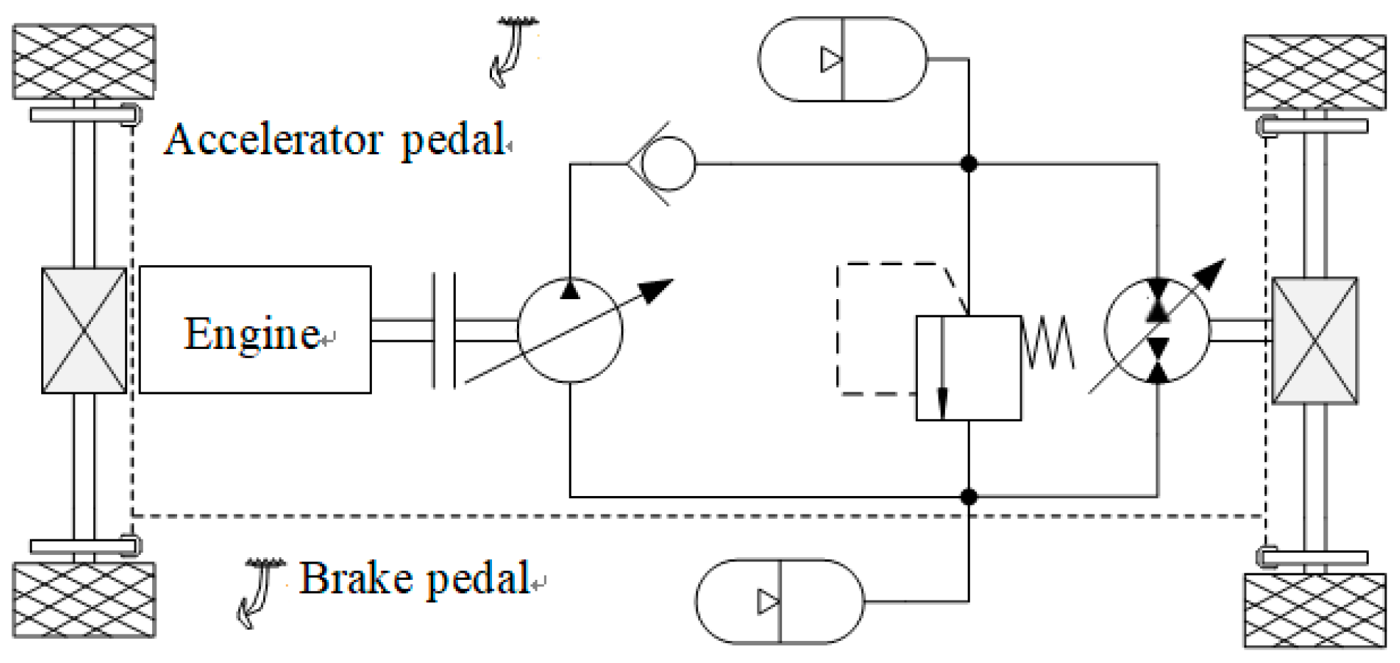
Figure 2.
Forward simulation model of the series-connected hydraulic hybrid vehicle system.
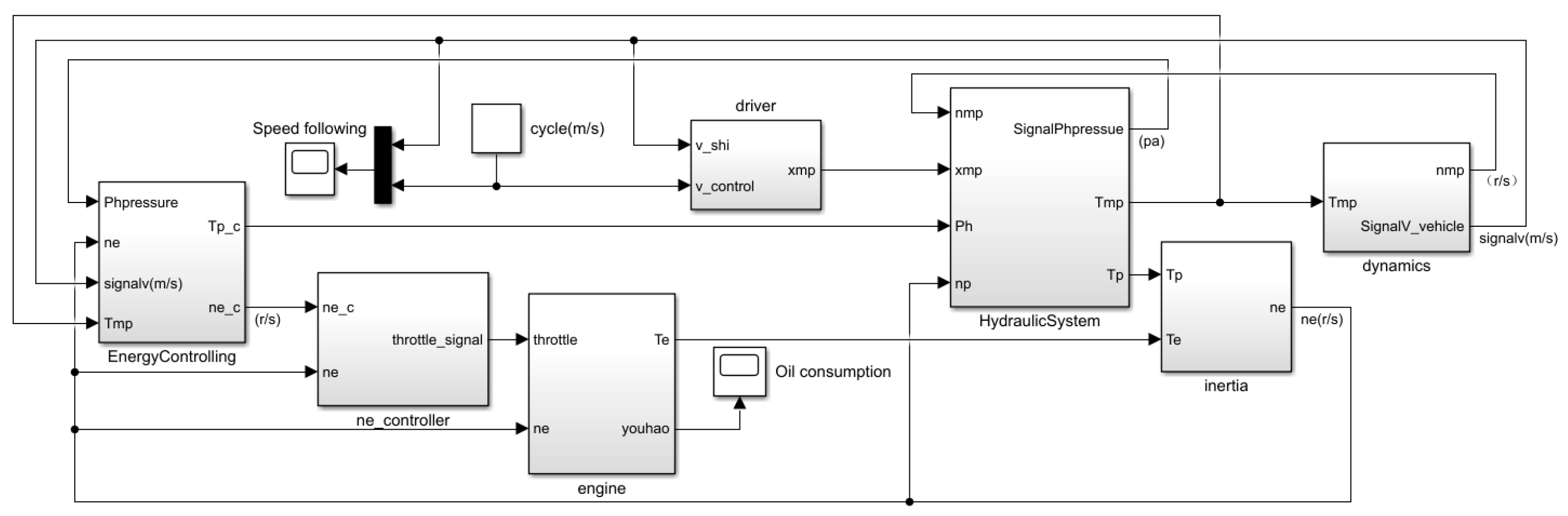
Figure 3.
Vehicle speed tracking of CYC_HWFET under high-speed cycle conditions.
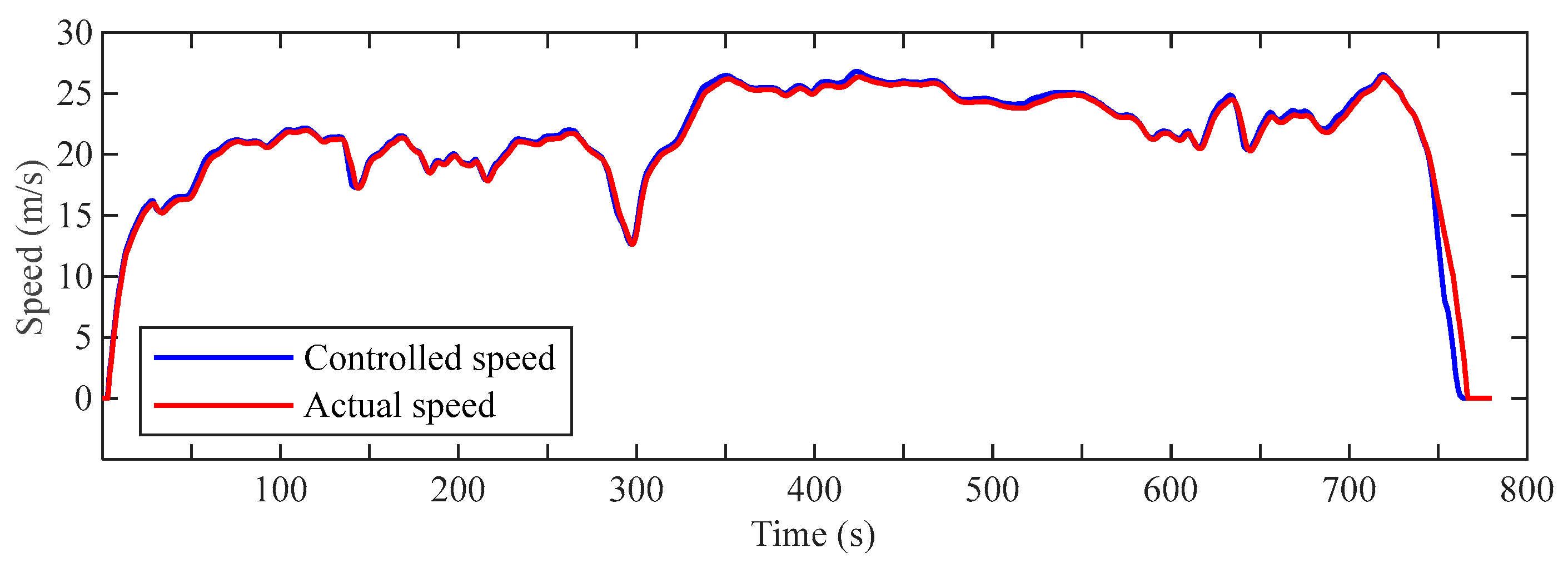
Figure 4.
Engine speed.
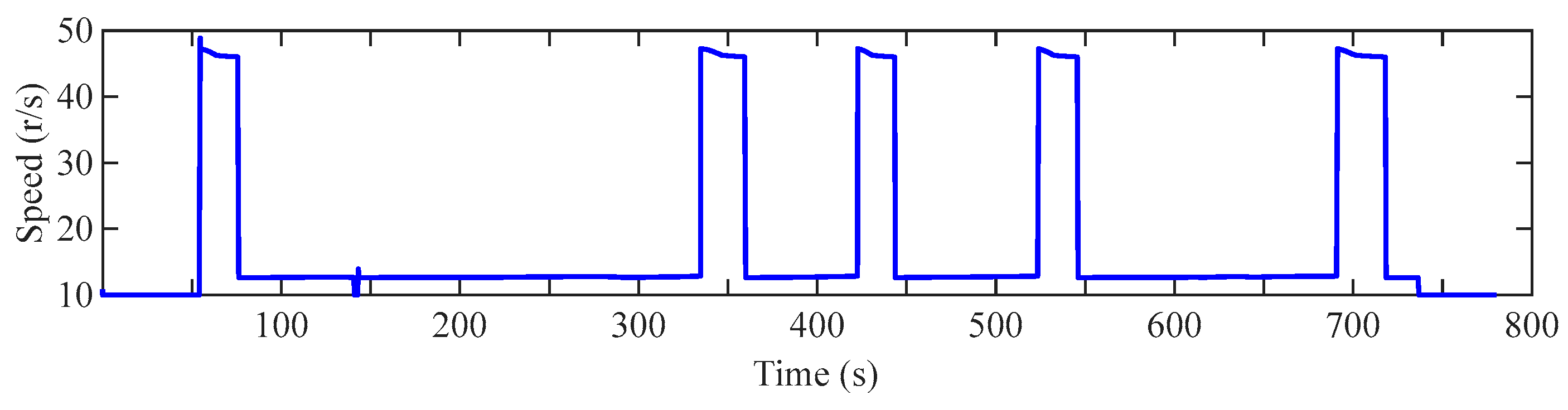
Figure 5.
Pressure change of accumulator.
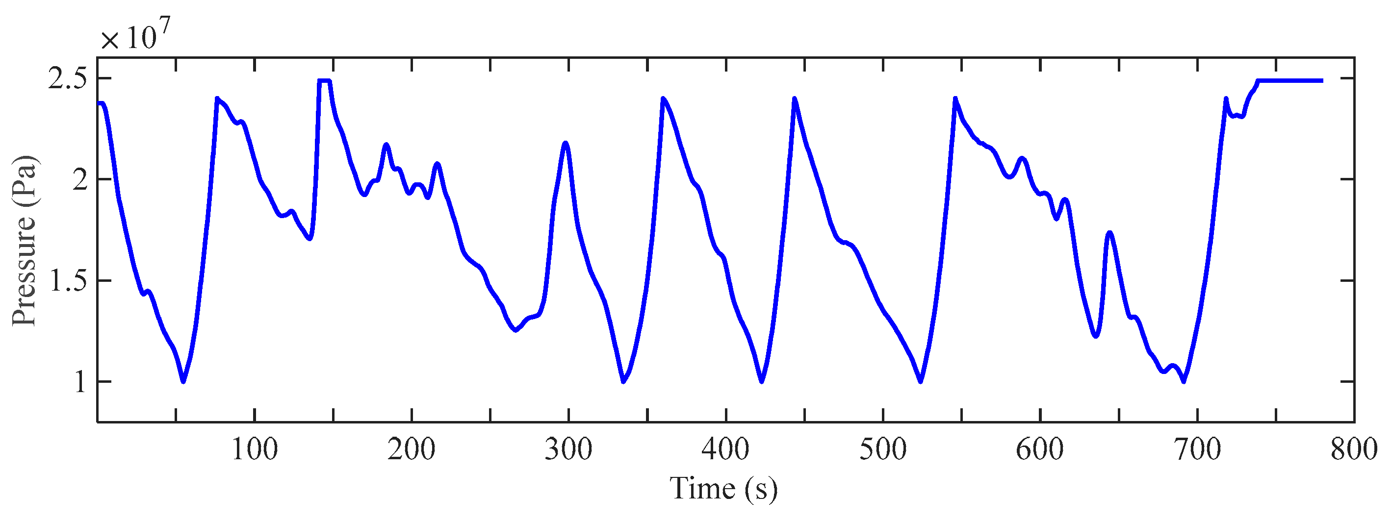
Figure 6.
Actual output torque of variable displacement pump/motor.
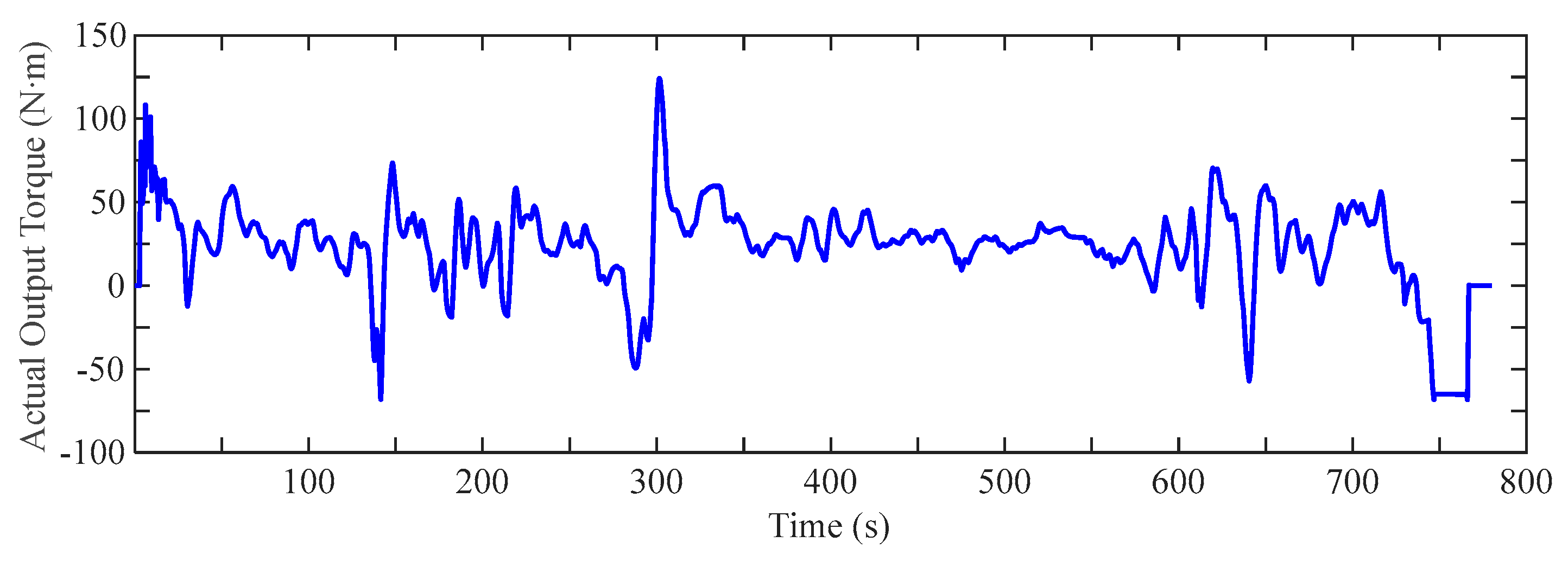
Figure 7.
Transmission gear.
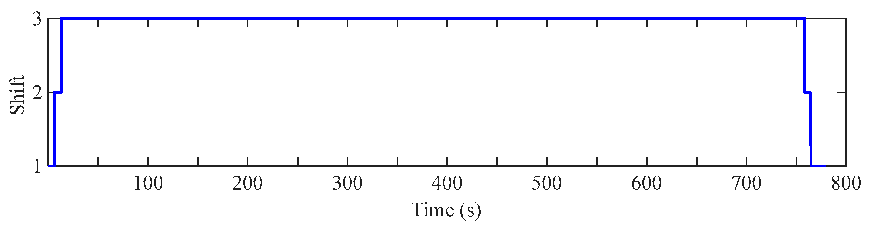
Figure 8.
Engine fuel consumption.
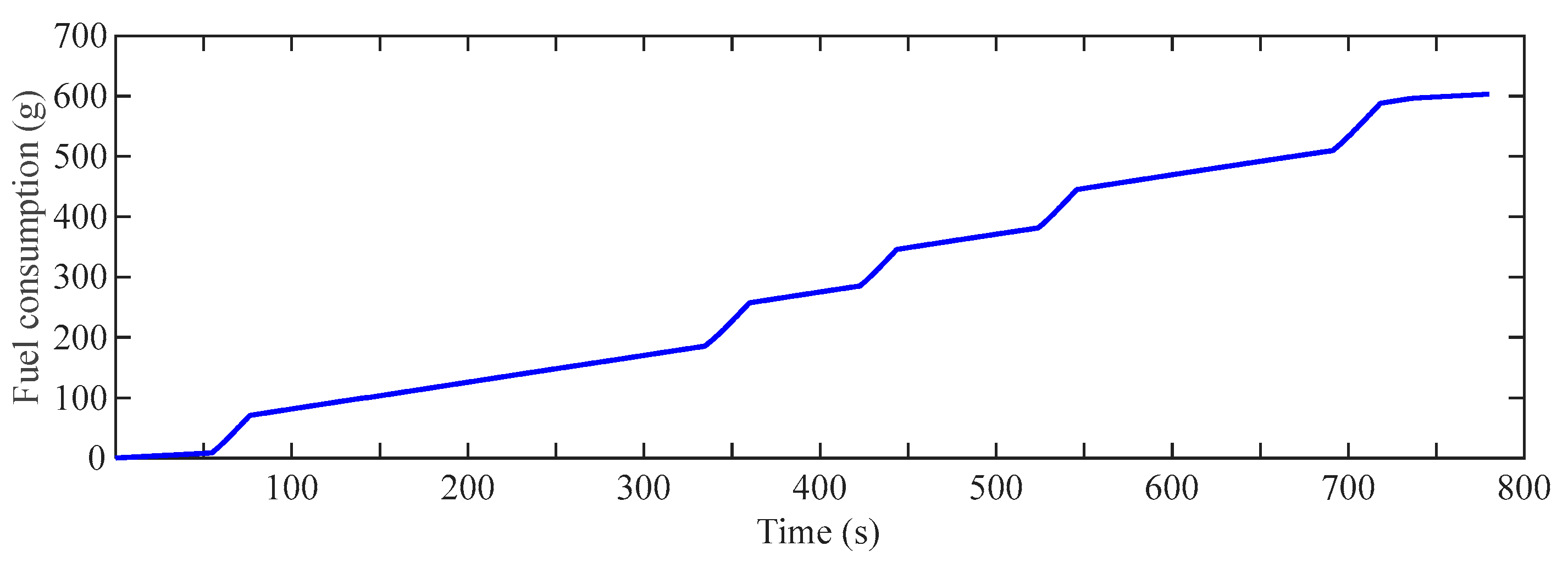
Figure 9.
Comparison chart of engine speed between multi-point control and single-point control of engine.
Figure 9.
Comparison chart of engine speed between multi-point control and single-point control of engine.
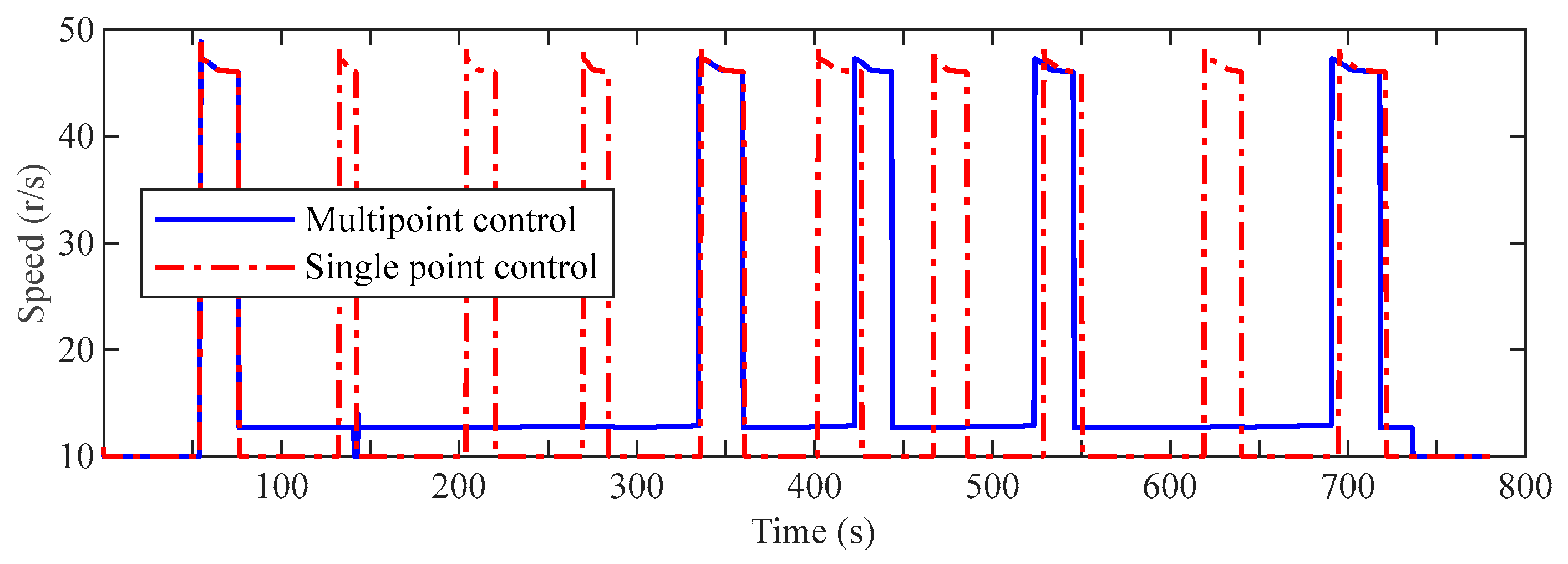
Figure 10.
Comparison chart of fuel consumption between engine multi-point control and engine single-point control.
Figure 10.
Comparison chart of fuel consumption between engine multi-point control and engine single-point control.
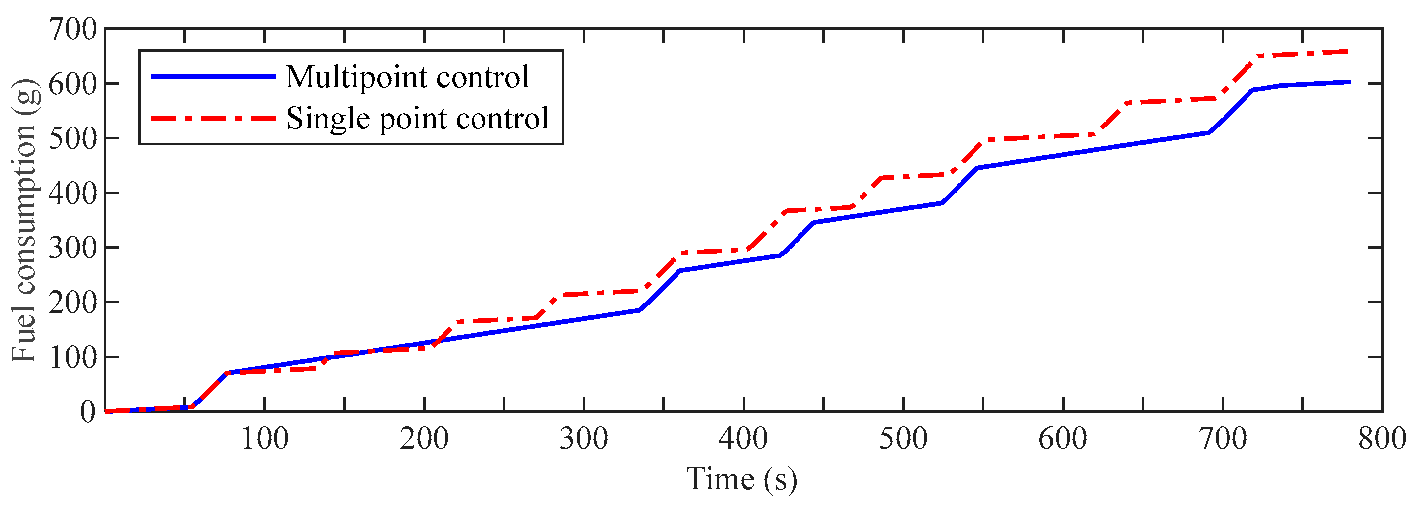

Table 1.
Energy management control rules for vehicles.
| Serial number | Condition | Carry out |
| 1 | If u=0 and p>p1 | Then ne=ne_idle |
| 2 | If p>p2 and Tp/m<0 | Then ne=ne_idle |
| 3 | If p≥p3 | Then ne=ne_idle |
| 4 | If p>p2 and Tp/m>0 | Then ne=ne_min |
| 5 | If p<p1 | Then ne=ne_max |
| 6 | Else | ne=ne_min |
Table 2.
Main parameters of series-connected hydraulic hybrid vehicle.
| Main parameters of vehicle | Numerical value |
| Total vehicle mass (m/kg) | 1470 |
| Windward area (A/m2) | 2 |
| Air resistance coefficient (CD) | 0.3 |
| Rolling resistance coefficient (f) | 0.1 |
| Wheel radius (R/m) | 0.3556 |
| 0~100km/h Acceleration time (t/s) | 14 |
| Maximum speed (vmax/km/h) | 150 |
| Maximum climbing degree (%) | 30 |
| Maximum engine power (Pmax/kW) | 81 |
| Maximum engine speed (nmax/rpm) | 6000 |
| Rated engine speed (nrated/rpm) | 4800 |
| Maximum engine torque (Tmax/N⋅m) | 180 |
| Transmission speed ratio (ij) | 3, 1.7, 1 |
| Main reduction ratio (ig) | 4.7 |
| Accumulator volume (V0/L) | 80 |
| Minimum working pressure (p1/MPa) | 10 |
| Maximum working pressure (p2/MPa) | 24 |
| Variable displacement pump displacement (Dp/ mL/r) | 63 |
| Variable displacement pump/motor displacement (Dp/m/ mL/r) | 63 |
Disclaimer/Publisher’s Note: The statements, opinions and data contained in all publications are solely those of the individual author(s) and contributor(s) and not of MDPI and/or the editor(s). MDPI and/or the editor(s) disclaim responsibility for any injury to people or property resulting from any ideas, methods, instructions or products referred to in the content. |
© 2026 by the authors. Licensee MDPI, Basel, Switzerland. This article is an open access article distributed under the terms and conditions of the Creative Commons Attribution (CC BY) license (http://creativecommons.org/licenses/by/4.0/).
Copyright: This open access article is published under a Creative Commons CC BY 4.0 license, which permit the free download, distribution, and reuse, provided that the author and preprint are cited in any reuse.