

Submitted:
06 September 2026
Posted:
08 September 2026
You are already at the latest version
Abstract
Manufacturing deviations in geared drivetrains alter tooth contact, transmission error (TE), mesh stiffness, bearing-transmitted forces, structural vibration and radiated noise, yet these effects are often studied in disconnected models. This methodological review develops a version-verified manufacturing-aware NVH workflow around Romax DT, with Romax Spectrum as the central system-dynamics environment. Official Romax Help and release documentation are used to establish capability and software-version boundaries, while peer-reviewed literature is used to assess physical evidence and validation requirements. A structured literature search and capability audit show that prior studies demonstrate individual links—measured geometry to LTCA/TE, Romax-based system vibration, acoustic coupling, or EOL correlation—but not the complete, version-audited chain. The proposed workflow connects measured cylindrical-gear flank data through GDE, loaded tooth contact analysis, 2025.1 advanced three-dimensional finite-element-based tooth stiffness in Gearbox Transmission Error (GBTE), flexible system response, Equivalent Radiated Power (ERP), detailed acoustic analysis and external experimental validation. It explicitly separates vendor-documented capability, peer-reviewed evidence and proposed external extensions such as wear-state updating, model calibration and EOL data assimilation. A falsifiable validation hierarchy is defined for comparing nominal, tooth-averaged and tooth-resolved measured states at contact/TE, housing-vibration and acoustic levels. The contribution is therefore methodological and reproducibility-oriented rather than new solver physics.
Keywords:
gearbox NVH
; Romax DT
; Romax Spectrum
; transmission error
; loaded tooth contact analysis
; measured flank geometry
; manufacturing variability
; Gear Data Exchange
; vibroacoustics
; digital twin
1. Introduction
The principal challenge in modern geared-drivetrain NVH research is no longer only the prediction of an ideal gear pair. The more difficult problem is to determine how geometric and assembly deviations that exist on a manufactured unit modify tooth contact, excitation, transfer paths and radiated sound. This distinction matters because a nominally identical set of gears can exhibit different contact states, transmission-error harmonics and vibration responses after manufacturing and assembly. Recent work on manufacturing deviations has likewise emphasized that the tolerance-affected physical system may behave differently from the idealized design model, and that the dominant deviations depend on the selected performance indicator [1].
Transmission error (TE) remains one of the most widely used excitation descriptors in gear-noise analysis, but its prediction is highly sensitive to modeling assumptions. A recent benchmark of commercial and research gear-contact tools reported substantial differences in peak-to-peak static transmission error between software environments, particularly when microgeometry, parallelism defects or complex system effects were introduced [2]. The consequence for research is important: a workflow should not be evaluated only by whether it produces a TE result, but also by how measured geometry, system deflection, tooth stiffness and local contact compliance enter the calculation.
The relevance of measured geometry is also increasingly explicit in the literature. Im et al. incorporated measured profile errors into a loaded tooth contact analysis and validated the resulting static transmission-error trends experimentally; the study further demonstrated that surface-waviness amplitude and spatial frequency can alter both peak-to-peak transmission error and its harmonic structure [3]. This type of result motivates a manufacturing-aware workflow in which coordinate-measuring-machine or gear-measuring-center data are not reduced only to pass/fail tolerance classes but are propagated into the excitation model itself.
Experimental uncertainty studies reinforce the same point at population level. Najib et al. examined spur-gear pairs with manufacturing errors in lead and profile slope, reported configuration-dependent static transmission-error changes of up to 8 μm at low torque, and found meaningful differences in dynamic response even for gears sharing the same macrogeometry [4]. The implication is that tolerance-affected excitation cannot be represented reliably by a single nominal gear model when the research objective is production consistency or unit-to-unit NVH variation.
A second issue is the circumferential distribution of deviations. Recent work has shown that identical nominal microgeometry amplitudes can generate different TE waveforms and sideband structures when the tooth-to-tooth distribution is changed [5]. Likewise, current waviness literature emphasizes that periodic micron-scale flank deviations can generate non-meshing tonal components and ghost orders [6]. These observations motivate preserving tooth identity and spatial structure wherever the metrology and CAE representation allow it, rather than reducing the manufactured state to one averaged flank.
Romax is particularly relevant to this problem because its software architecture combines gear contact analysis, drivetrain static analysis, dynamic response, flexible finite-element components and acoustic prediction within a common drivetrain model. The official 2022 release introduced import of measured cylindrical-gear flank data through the Gear Data Exchange (GDE) format specified by VDI/VDE 2610 and explicitly described the subsequent use of these data in microgeometry and GBTE analyses for contact and transmission-error evaluation [7]. The 2025.1 release extended the higher-fidelity tooth-stiffness formulation to GBTE, allowing the three-dimensional finite-element-based coupled tooth-bending model to be used for system-level linear and tilt transmission-error prediction [8].
The present paper therefore does not attempt to rank Romax against competing CAE platforms or to restate the product documentation as a feature catalogue. Instead, it asks a research-method question: how can the documented Romax capabilities be assembled into a traceable manufacturing-aware gearbox NVH workflow, what outputs can be obtained at each stage, and where do external measurements, solvers or data-processing steps remain necessary? This perspective is intended to support research programs that connect measured gear geometry, tooth-to-tooth variability, misalignment, contact analysis, drivetrain dynamics and end-of-line vibration or acoustic measurements.
The measurement end of the chain also has a mature evidence base that can be used as an external validation layer. Palermo et al. demonstrated transmission-error measurement on an all-electric vehicle gearbox and showed its usefulness as an NVH indicator for gear microgeometry development [9]. At production level, Su et al. linked transmission EOL vibration measurements to vehicle vibration, acoustic parameters and sound-quality assessment across a population of automatic transmissions [10]. These studies do not validate a Romax measured-geometry workflow directly, but they provide independent targets for source-level TE validation and end-of-line response validation.
2. Research Objective, Scope and Evidence Framework
The main objective is to define a practical source-to-radiation workflow in which manufacturing information can be introduced as early as the tooth-flank representation and carried forward through contact, excitation, dynamic response and acoustic evaluation. The capability baseline is Romax Software 2025.1. Release documentation from 2022 to 2025.1 is used to establish when key functions became available, while the 2026.1 release is treated only as a forward-looking update and is not used to redefine the 2025.1 baseline [7,8,11,12,13,14,15].
Three evidence levels are separated throughout the paper. First, vendor-documented capability means that the official Help or release documentation explicitly describes a function or workflow. Second, peer-reviewed demonstrated application means that the open literature reports use of Romax or an equivalent physical workflow for a relevant task. Third, proposed research extension identifies a step that is methodologically reasonable but is not documented as an automatic native workflow and therefore requires external scripting, measurement, model updating or manual iteration. This separation is essential for avoiding the common error of presenting a technically plausible workflow as a fully verified built-in capability.
The scope is restricted to geared-drivetrain NVH and manufacturing-aware simulation. Durability, lubrication and bearing-life functions are included only when they affect the NVH chain or provide relevant state variables. The primary focus is cylindrical spur and helical gears because this is where the measured-flank GDE workflow, detailed microgeometry tools and the most direct GBTE chain are documented. Planetary systems are included where the system architecture is relevant, but the paper does not claim identical fidelity for every gear type or product option.
2.1. Research Gap and Explicit Contribution
The literature already contains strong but mostly separate building blocks for manufacturing-aware gear NVH. Measured or error-affected tooth surfaces have been propagated into TCA/LTCA and transmission-error calculations [3,16]; Romax-centered studies have linked gear excitation to rigid-flexible drivetrain response and, in some cases, to Actran acoustic prediction and vehicle testing [17,18,19]; data-driven work has linked gear inspection variables directly to noise-bench outcomes [20]; and digital-twin studies have connected manufacturing state to loaded contact performance [21]. A recent gear-NVH digital-twin review further concluded that metrology, physics-based simulation and test data remain insufficiently integrated in end-to-end workflows [22]. Within the literature identified for the present study, however, no single publication was found that documents a version-verified Romax 2025.1 implementation from measured cylindrical-gear flank state through advanced GBTE to system vibroacoustics while also separating native capability, external steps and validation requirements.
Accordingly, the contribution of this paper is not a new contact, dynamic or acoustic solver. It is an implementation and reproducibility framework that operationalizes one concrete research path: (i) it establishes the software-version boundary of the principal Romax functions required by the workflow; (ii) it maps the measured-geometry → contact/LTCA → GBTE → dynamic response → ERP/full-acoustic chain and states where information can be lost or where third-party tools remain necessary; and (iii) it converts that chain into testable research questions and pre-defined validation gates for matched manufacturing and NVH data. This positioning is intentionally narrower than a general digital-twin or CAE review and broader than a single nominal Romax case study.
The novelty claim should therefore be interpreted as methodological integration with explicit evidence provenance. Any future empirical paper based on this framework must add its own experimental novelty—such as unit-specific measured flank data, tooth-resolved spatial variability, wear-state evolution or matched end-of-line measurements—rather than treating the availability of commercial software functions as a scientific result in itself.
The present work is also deliberately differentiated from two earlier publications by the author. The digital-twin review in [22] maps field-level gaps across modeling, data integration and validation but does not audit one commercial implementation path at version level. The tooth-level barreling study in [5] is a controlled mechanism study of circumferential microgeometry distribution and TE sidebands, not a Romax workflow paper. Here, those works serve respectively as gap-level context and mechanism-level evidence; no results or figures from them are reused as new findings.
2.2. Literature Search and Capability-Audit Protocol
The evidence review was conducted as a structured technical search rather than a PRISMA-style systematic review. Peer-reviewed literature was identified through Consensus using iterative query families centered on: (i) Romax + transmission error + NVH; (ii) measured tooth flank/profile + LTCA/TCA + transmission error; (iii) manufacturing deviations + gearbox vibration/noise; (iv) gear digital twin + measured geometry/manufacturing state; (v) gear wear + transmission error/dynamics; and (vi) end-of-line transmission vibration + acoustic/sound-quality validation. Candidate papers were screened for direct relevance to at least one link of the manufacturing-state → contact/TE → system response → acoustic/EOL chain. Selected records were fetched for full bibliographic metadata and DOI details were cross-checked against publisher or authoritative bibliographic records.
In parallel, the official Romax 2025.1 Help corpus and release documentation from 2022 through 2025.1 were audited to establish the earliest verified release of the principal functions used in the workflow. The 2026.1 release was consulted only as an outlook. Vendor documentation is used only to support software-capability statements; it is not treated as independent validation of model accuracy. Because the literature search is purposive and implementation-focused, the novelty statement is framed conservatively as 'within the literature identified by this search' rather than as an exhaustive claim over all published work.
The capability-evidence items retained for the final submission audit are summarized in Appendix A (Table A1).

Table 1.
Closest prior work and the residual methodological gap addressed by the present framework.
| Study | Main link demonstrated | Romax-specific? | Matched test/EOL? | Gap relative to present framework |
| Bejar et al. (2024) [2] | Cross-software static TE benchmarking with microgeometry and defects | Includes Romax in benchmark | No matched manufacturing-to-EOL chain | Benchmarks TE solvers; does not propagate measured unit state to vibroacoustics. |
| Im et al. (2025) [3] | Measured profile errors → LTCA/STE with experimental validation | No | STE test | Strong measured-geometry source validation, but no system vibration/acoustic propagation. |
| de Walque & Jamaluddin (2023) [17] | Romax Spectrum structural response → Actran vehicle acoustics | Yes | Acoustic/vehicle workflow | Strong downstream vibroacoustics, but not measured gear-manufacturing state. |
| Yang et al. (2026) [19] | Romax reducer model, gear measurement, microgeometry optimization and vehicle verification | Yes | Vehicle-level test | Demonstrates design/test closure, but not a version-audited GDE → advanced-GBTE → matched-unit EOL chain. |
| Su et al. (2024) [10] | Transmission EOL vibration → vehicle vibration/acoustic sound-quality correlation | No | Yes, EOL + vehicle | Strong production validation endpoint without a physics-based measured-geometry propagation model. |
| Horvath & Zelei (2025) [22] | Gear-NVH digital-twin gap map across metrology, simulation and validation | No specific implementation | Review evidence | Defines the broad field gap; does not operationalize one version-specific CAE workflow. |
3. Romax Architecture Relevant to Manufacturing-Aware NVH
Romax DT is best treated as a shared drivetrain modeling environment whose analysis capability depends on the active product and options. For the present workflow, Romax Spectrum is the central NVH product because it connects gear excitation with system dynamics, flexible components and vibroacoustic results. Romax Enduro is relevant where detailed gear and spline contact, rating or manufacturing-process-oriented analyses are needed. Romax Spin extends bearing-contact and bearing-dynamics fidelity, while Romax Energy addresses losses and efficiency. Dynamic Fusion provides model translation to external multibody environments such as Adams or Modelica when a third-party MBD representation is required [14,23].
A key advantage of this architecture is continuity of the drivetrain model across analysis layers. Shafts, bearings, gears, housings and operating load cases are not independent stand-alone models; their static deformation and connection states can influence gear-mesh alignment and contact conditions, and the resulting excitation can then be used in dynamic analysis. For research, this makes Romax particularly suitable for experiments in which a manufacturing variable is expected to affect more than one local quantity. A bearing preload change, for example, may modify shaft alignment and gear contact rather than acting only as an isolated bearing parameter.
Table 2 summarizes the functional role of the principal Romax components in the proposed workflow.
4. From Nominal Geometry to Measured Manufacturing State
4.1. Designed Microgeometry and Tooth-Resolved Manufacturing States
The manufacturing-aware chain begins by separating designed microgeometry from the as-manufactured tooth-flank state. The Romax 2025.1 Help contains dedicated gear micro-geometry, pitch-error and measured-flank workflows for detailed cylindrical gears and distinguishes designed and measured geometry representations. The available tools can retain non-default tooth information in relevant microgeometry and pitch-error contexts, but the exact tooth/flank granularity depends on the selected definition or import route and on the data actually contained in the metrology file. Accordingly, this paper uses the term tooth-resolved only when tooth identity is demonstrably retained; it does not assume that every GDE or measurement export contains a complete per-tooth surface topography [23].
This distinction is central for research on order topology. A periodic deviation repeated with a circumferential pattern is expected to create a different excitation signature from a localized deviation confined to one tooth or a small group of teeth. The software representation alone does not prove the resulting order structure; however, it provides the input granularity required to test such hypotheses numerically. The research task should therefore preserve tooth identity whenever the measurement system and import format support it rather than averaging all teeth into one nominal surface.
This distinction is now directly testable as a mechanism-level hypothesis. In a controlled tooth-level barreling study, the same nominal barreling magnitude produced different TE modulation and sideband activity when the circumferential pattern was harmonic, phase shifted, clustered or random [5]. That study was performed in a different simulation environment, so it is not evidence of a Romax implementation; it is used here as independent physical motivation for using Romax microgeometry and pitch-error mechanisms in a tooth-resolved manner whenever the selected definition or imported dataset actually preserves tooth identity.
4.2. GDE Import and Measured Tooth-Flank Geometry
The most important documented bridge between manufacturing metrology and NVH simulation is the GDE workflow. Romax DT 2022 introduced automated import of cylindrical-gear tooth-flank measurement data using the open Gear Data Exchange format defined by VDI/VDE 2610. The release documentation states that gears with imported measurement data can subsequently be analyzed using microgeometry and GBTE analysis to evaluate load distribution, transmission error and contact stress. The same documentation also describes comparison of measured data with designed and virtually manufactured forms [7].
For a research workflow, GDE should therefore be treated as a semantic interface rather than merely a file-conversion convenience. The measurement system provides a geometric state; GDE transfers that state into the CAE model; and the contact calculation converts the measured state into physically interpretable quantities such as contact pressure, stiffness and TE. This chain is much more valuable than correlating a single geometric tolerance value directly with an end-of-line vibration level because it inserts a physics-based intermediate layer.
The limitation is equally important. A raw CMM point cloud, a standardized gear-measurement report and a GDE representation are not automatically equivalent. The imported representation depends on the information contained in the source file and on the measurement strategy. Consequently, a study should document which deviation quantities were transferred, whether all teeth and both flanks were represented, how missing regions were treated and whether the imported surface corresponds to profile/lead/pitch descriptors or to a denser topographic representation.
The need to retain spatial detail is also supported by measured-geometry and waviness-focused contact research. Wang et al. reconstructed helical-gear surfaces with waviness and showed that waviness amplitude, frequency and distribution affect meshing characteristics and TE [24]. Liang et al. built error-affected hypoid tooth surfaces from discrete measured error points and used contact/finite-element analysis to study contact pattern and TE, with rolling experiments providing an independent check of the predicted fluctuation [16]. A broader review of EV gear waviness further identifies ghost orders, metrology limitations and insufficient integration between measured surface state and physics-based NVH models as open research needs [6]. The Romax workflow is therefore most valuable when GDE or another supported measured-flank route preserves the deviation content needed by the research question; it should not be assumed that every metrology export contains equivalent information.
5. Loaded Tooth Contact Analysis and Gearbox Transmission Error
5.1. LTCA as the Manufacturing-to-Excitation Bridge
Loaded tooth contact analysis is the core physical bridge between flank geometry and drivetrain excitation. The Romax documentation describes the tooth-contact formulation as a combination of tooth-bending compliance and local contact compliance. In the 2022.1 release, an advanced tooth-bending stiffness model based on a three-dimensional finite-element approach was introduced to capture edge effects, elastic coupling within a tooth and coupling between neighboring teeth that are not represented by the faster plate-based approximation [11]. The advanced model transitioned to general availability in 2023.1 [12].
Independent literature supports the need for this level of scrutiny. Bejar et al. showed that predicted static transmission error can vary substantially between gear-contact software tools when microgeometry, system complexity or mounting defects are introduced [2]. This does not imply that one tool is universally superior; rather, it demonstrates why the selected stiffness model and system representation must be reported explicitly when TE is used as an NVH predictor.
5.2. Advanced Tooth Stiffness in GBTE
The 2025.1 release is a key version boundary for the proposed workflow. In this release, the advanced three-dimensional finite-element-based tooth stiffness model became available in Gearbox Transmission Error analysis and in static analysis with microgeometry. According to the official release documentation, this combines the coupled tooth-bending formulation with the system-wide GBTE representation of gear-mesh stiffness and excitation. GBTE can report both linear/transverse transmission error and tilt or misalignment transmission error caused by lateral movement of the mesh center of pressure during the tooth pass [8].
This is especially relevant for manufacturing and assembly research because a measured flank deviation may change more than the scalar peak-to-peak TE. It can move the contact patch, alter local load distribution, modify effective mesh stiffness and generate tilt excitation. The 2025.1 release also added amplitude and phase reporting for the first three harmonics of tilt transmission error in the NVH results tables [8]. A research workflow should therefore preserve harmonic and directional information instead of reducing the contact result to a single PPTE value whenever the downstream vibration model is sensitive to excitation direction.
5.3. Validation Implications
Peer-reviewed evidence provides two complementary validation messages. First, Zhang et al. demonstrated a Romax-based three-dimensional parametric contact model for a helical planetary gear train, using LTCA to evaluate contact pressure and transmission error across tooth-modification samples and then building a response-surface-based reliability sensitivity analysis [25]. This supports the use of Romax as a parameter-study environment for microgeometry-driven excitation research. Second, Im et al. showed with an independent LTCA formulation that measured profile errors and surface waviness influence TE harmonics and that simulation should be checked against experimental static transmission error [3]. Together, these studies justify a workflow in which measured geometry enters LTCA, but they also show that the numerical chain should not be considered experimentally validated merely because the geometry is measured.
The uncertainty literature adds a robustness requirement. Najib et al. used multiple manufactured spur-gear configurations together with probabilistic sampling and experimental comparison, showing that manufacturing errors can shift both STE and dynamic response [4]. Lahoti et al. reported a simulation-and-test workflow in which TE/contact-pattern optimization was followed by manufacture of revised parts and testing; the optimized design reduced measured gear-whine levels by more than 6 dB in most investigated cases [26]. These studies support a validation hierarchy in which contact and TE trends are first checked near the excitation source before conclusions are drawn from housing vibration or radiated sound.
6. From Gear Excitation to System-Level Vibration
The next layer propagates gear-mesh excitation through shafts, bearings, connections and flexible housings. A manufacturing-aware study must include this layer because the acoustic consequence of a given TE harmonic depends strongly on transfer-path dynamics. Two nominally similar gearsets can therefore produce different housing responses if bearing stiffness, preload, shaft alignment or housing modes differ. Independent work has shown that pitch deviation, helix-tilt deviation and radial runout can change harmonic TE and the resulting transmission vibration response, illustrating that manufacturing effects need to be propagated beyond the contact model [27]. The Romax system model supports load cases and duty cycles in which operating speed, torque, powerflow and selected component states can vary, allowing the researcher to examine whether a manufacturing effect remains important across the operating envelope rather than at one isolated point [23].
Flexible finite-element components are important for this stage. The 2025.1 Help documents FE-component workflows, static and dynamic condensation, modal analysis and access to common third-party FE formats including Nastran, OptiStruct, Ansys and Abaqus [23]. The 2023.1 release added dynamic-substructure export in MSC Nastran format for further analysis or implementation in larger end-product assemblies [12]. Thus, the Romax model can either remain the primary system-dynamics environment or act as a reduced drivetrain subsystem inside a larger vehicle-level calculation.
This distinction is useful when designing validation experiments. If the research question concerns gear-specific housing vibration near the reducer, a Spectrum-centered model may be sufficient. If the question concerns body attachment points, cabin noise or vehicle-level transfer paths, a substructure or external MBD/FE workflow may be more appropriate. Dynamic Fusion 2025.1 documents translators for Adams and Modelica, while earlier Romax releases introduced the R2A model-transfer route to Adams [7,14]. The existence of these interfaces should not be confused with automatic equivalence of the two models; component mapping, connection representation and reduction assumptions must still be checked.
7. Housing Vibration and Radiated Noise
7.1. Equivalent Radiated Power as a Screening Metric
Romax Spectrum includes Equivalent Radiated Power as a fast approximation of radiated acoustic power. The official 2022 release documentation describes ERP as an estimate that treats the vibrating component as an ideal sound source, generally providing an approximate upper limit; it also notes that ERP is more accurate at higher frequencies and can significantly overpredict at lower frequencies. The intended use is rapid design comparison, sensitivity analysis or optimization before a more detailed acoustic simulation is run [7].
This distinction is highly appropriate for manufacturing-variability studies. A large design-of-experiments campaign may contain hundreds or thousands of geometry or assembly states, for which full acoustic calculations are impractical. ERP can be used as a second-stage screening metric after TE and structural response, while only selected worst-case, best-case or representative states are passed to the full acoustic model. In the 2022 example included in the release documentation, ERP required seconds while the corresponding acoustic calculation required hours; the exact ratio is model-dependent, but the example illustrates the intended computational hierarchy [7].
A complementary example is provided by Son et al., who used a validated finite-element gearbox model and Equivalent Radiated Power as an optimization objective for radiated-noise reduction, illustrating the value of ERP as a location-independent screening metric before detailed acoustic prediction [28].
7.2. Full Acoustic Analysis and Actran Coupling
For absolute acoustic prediction, the workflow must go beyond ERP. The Romax Help contains Acoustic Analysis Setup and Acoustic Export workflows, including coupling to Actran [23]. Release documentation also shows continuing development of high-frequency acoustic performance and compatibility with Actran versions, reflecting the increasing importance of electric-powertrain frequency ranges [12,13]. A peer-reviewed SAE study by de Walque and Jamaluddin used Romax Spectrum to calculate e-powertrain structural vibration and Actran to compute acoustic radiation, extending the workflow toward vehicle-level structure-borne and airborne noise [17].
The broader literature confirms why this separation is necessary. Han et al. modeled a gear–shaft–bearing system, used the resulting bearing forces to excite a housing finite-element model and then applied an acoustic boundary-element formulation; the simulated vibration and noise were checked on a test bench [29]. Fang and Zhang similarly demonstrated a coupled electric-machine and gearbox vibroacoustic workflow with modal structural response and boundary-element acoustic prediction, validated in a semi-anechoic room [30]. These studies reinforce that the final acoustic response is a transfer-path and radiation problem, not a direct function of TE amplitude alone.
Romax-specific peer-reviewed applications provide additional evidence for this staged interpretation. Huang et al. used Romax for gear TE and system vibration analysis and Actran for acoustic prediction in a rigid-flexible drive-system model, reporting reduced vibration and acoustic levels after optimization [18]. More recently, Yang et al. built a parametric Romax reducer model and a rigid-flexible electric-drive model for a vehicle gear-whine problem; simulation was correlated with tests, and microgeometry optimization was subsequently confirmed at vehicle level [19]. These studies demonstrate the practical feasibility of the Romax-centered excitation-to-response chain, while also showing that experimental correlation remains part of the engineering workflow rather than an optional final illustration.
8. Parametric Studies, Manufacturing Variability and Optimization
Manufacturing-aware research becomes computationally demanding as soon as more than a few deviations are considered simultaneously. Gear profile and lead variations, pitch errors, bearing preload, component position, temperature and load state can interact. A naive full-factorial design therefore becomes impractical. Romax Parametric Study and Batch Running provide a framework for automated variable definition, targets, results and output actions, and these capabilities have been expanded across multiple releases [7,8,11,12,13].
The recommended research use is not to sweep every available parameter. A staged approach is more defensible: first, define physically plausible manufacturing and assembly variables from measurement or tolerance data; second, perform screening or sensitivity analysis on TE/contact indicators; third, propagate only influential variables to the dynamic and acoustic layers; fourth, select representative states for expensive full acoustic analysis or experiment. This hierarchy mirrors the motivation of recent global sensitivity work on gearbox manufacturing deviations, where the dimensionality of the tolerance space made brute-force exploration unattractive and different deviations dominated load capacity, efficiency and NVH indicators [1].
A practical advantage of the Romax workflow is that the same model can be evaluated at different fidelity levels. Fast plate-based contact or reduced result sets can be used in screening, while advanced tooth stiffness, detailed FE components and full acoustic analysis are reserved for the reduced set of influential cases. The research value lies in reporting this hierarchy transparently rather than presenting every simulation as if it had identical numerical fidelity.
Two complementary uncertainty strategies emerge from the literature. One is measurement-informed sampling, in which statistical distributions or bounded manufacturing errors are propagated into TE and dynamic response [4]. The other is global sensitivity analysis, in which the aim is to identify the relatively small subset of deviations that dominates a chosen performance indicator [1]. For Romax studies, the most defensible implementation is therefore a staged one: use measured distributions where available, screen with contact/TE outputs, apply variance- or sensitivity-based ranking externally when required, and reserve flexible-system and acoustic calculations for the influential portion of the design space.
9. Proposed Manufacturing-Aware Research Workflow
Figure 1 summarizes the proposed manufacturing-aware source-to-radiation workflow. The graphical chain is complemented by Table 3, which lists the research control required at each stage.
The workflow deliberately separates deterministic propagation from uncertainty treatment. A measured tooth flank should not be interpreted as a complete digital twin unless assembly state, bearing condition, preload, temperature, housing stiffness and damping are also sufficiently characterized. In a research study, the most useful question is often not whether the absolute amplitude is exactly predicted, but whether the model correctly predicts how a controlled manufacturing change moves TE harmonics, structural response and radiated-noise indicators relative to a baseline.
10. Research Questions and Falsifiable Hypotheses
The workflow is intended to generate falsifiable comparisons rather than descriptive software outputs. The central questions are whether retaining manufacturing-state information improves prediction of TE topology, whether the resulting excitation ranking survives propagation through the structural transfer path, whether fast screening metrics preserve the ranking obtained from higher-fidelity analyses, and whether matched unit-specific metrology explains measured EOL outliers better than nominal or tooth-averaged models. Table 4 expands these questions into testable sub-problems and identifies the minimum validation data required for each.
11. Validation Strategy and Peer-Reviewed Evidence
A software-centered methodology paper is scientifically useful only if documented capability is separated from demonstrated evidence. Table 5 therefore maps the principal workflow claims to peer-reviewed studies. The studies are not treated as proofs that every Romax option is validated for every gearbox. Instead, they identify which links in the proposed chain have been demonstrated in Romax-specific applications, which are supported mainly by independent gear-dynamics or metrology research, and which remain research hypotheses requiring matched-unit validation.
The strongest Romax-specific evidence concerns three links: microgeometry/contact analysis, system vibration, and coupling to external acoustic analysis. Zhang et al. used a three-dimensional Romax contact model and LTCA in a planetary-gear sensitivity study [25]. Huang et al. combined Romax mechanical response with Actran acoustics [18], while de Walque and Jamaluddin used Romax Spectrum and Actran in an e-powertrain-to-vehicle vibroacoustic workflow [17]. Yang et al. provide a recent vehicle-oriented example in which a Romax reducer model, rigid-flexible system analysis, gear measurement and test correlation were combined before microgeometry optimization [19].
The measured-manufacturing-state link is supported by a wider evidence base rather than by one universal software validation. Im et al. validated an LTCA model containing measured profile errors against STE measurements [3]; Wang et al. examined waviness-resolved LTCA [24]; Najib et al. quantified manufacturing-error effects on static and dynamic responses [4]; Liang et al. propagated measured error points into contact and TE analysis with rolling-test verification [16]; and the tooth-distribution study of Horvath and Zelei showed that circumferential microgeometry patterns can alter TE sideband topology even at fixed nominal amplitude [5]. Consequently, a Romax case study that imports measured geometry should be evaluated against these physical expectations, not merely against successful file import.
Two adjacent research streams help define the remaining gap. Lei et al. developed a digital-twin manufacturing framework in which tooth-surface grinding parameters were connected to numerical loaded tooth contact performance, demonstrating that manufacturing state can be embedded in a physics-based digital representation [21]. Lee and Park, by contrast, linked gear inspection data directly to semi-anechoic noise-bench results using machine-learning models [20]. These approaches are valuable but terminate at different points of the chain: the former emphasizes manufacturing-to-contact performance, whereas the latter emphasizes data-driven inspection-to-noise prediction. The present framework targets the missing deterministic middle path—measured geometry to contact/TE to structural response to acoustic indicators—while preserving an external statistical branch for population-level learning.
The measurement literature supports a two-level validation ladder for the proposed framework. At source level, directly measured TE can test whether the nominal, tooth-averaged and tooth-resolved geometry models predict the correct mesh-order and sideband structure [9]. At production-response level, EOL vibration can be compared with unit-specific or population-level acoustic outcomes, as demonstrated independently for automatic transmissions [10]. Accordingly, agreement at the housing or acoustic level should not be accepted as evidence of correct gear-contact physics unless the upstream contact/TE gate is also satisfied.
12. Limitations and Research Gaps
The strongest limitation of the workflow is that manufacturing-aware does not automatically mean fully manufacturing-resolved. The GDE interface is powerful, but its usefulness depends on the content and resolution of the measurement data. A study that imports averaged profile and lead deviations does not represent the same physical state as one that retains tooth-resolved topography and pitch variation. This distinction should be stated explicitly in every case study.
A second limitation is damping and assembled-boundary-condition uncertainty. Even if the gear contact state is represented accurately, housing vibration and sound radiation can remain sensitive to joint stiffness, bearing support conditions, material damping, lubricant state, temperature and mount boundary conditions. These parameters are often less well measured than gear geometry. Consequently, correlation of absolute vibration or SPL should include uncertainty bounds or model-updating steps rather than attributing every amplitude mismatch to the gear-contact model.
A third limitation concerns wear. The 2025.1 Help documents local linear wear results in the thermoplastic-gear context, but it does not document an automatic iterative loop in which calculated wear modifies the tooth surface and the modified geometry is then fed back into TE and NVH analysis [23]. Therefore, a general wear → updated geometry → TE → vibration → noise chain should be presented as an external or scripted research extension. This distinction matters because current peer-reviewed wear research explicitly shows that wear-induced profile evolution changes TE and dynamic response. Chin et al. demonstrated that TE is sensitive to gear-wear evolution [31], while Zhang et al. developed an iterative friction-wear model in which tooth-surface parameters, time-varying mesh stiffness and unloaded static TE are updated during wear progression [32]. A Romax-based life-state study can emulate the state-update logic by re-importing measured or externally generated worn geometry and rerunning LTCA/GBTE/NVH, but that workflow must be described as external iteration rather than a native coupled wear solver.
A fourth limitation is experimental workflow automation. Romax supports model and result export, measured flank import and comparison, but the examined documentation does not establish a dedicated automatic end-of-line model-updating workflow that ingests test-bench order spectra and identifies model parameters. Correlation to EOL vibration or acoustic data therefore requires an external data pipeline, careful component identity matching and statistical treatment of measurement uncertainty. This should be distinguished from a purely data-driven route: Lee and Park demonstrated that gear inspection data and noise-bench measurements can be linked successfully with machine-learning models [20], but such a predictor does not by itself establish the causal geometry → contact/TE → transfer-path chain targeted here. A hybrid workflow can use both approaches, with Romax providing physics-derived intermediate variables and external statistics/ML quantifying population-level relationships.
Finally, version boundaries matter. Features should not be back-projected to earlier releases. For example, advanced three-dimensional tooth stiffness appeared first as a 2022.1 capability, became generally available for single-mesh microgeometry analysis in 2023.1, and was extended to GBTE in 2025.1 [8,11,12]. Likewise, MSC Nastran dynamic-substructure export was added in 2023.1 [12]. Reporting the exact software version is therefore part of methodological reproducibility.
13. Version-Specific Capability Timeline
Table 6.
Version-specific capability milestones relevant to the 2025.1 workflow baseline.
| Version | Verified capability milestone | Research significance |
| 2022 | GDE measured flank import; GDE export; ERP; Romax-to-Adams export | Measured geometry can enter microgeometry/GBTE; fast acoustic screening becomes available. |
| 2022.1 | Advanced 3D FE-based tooth-bending stiffness introduced (initial release stage) | Higher-fidelity LTCA can capture coupling and edge effects beyond the faster plate model. |
| 2023.1 | Advanced tooth stiffness reaches general availability for single-mesh microgeometry analysis; MSC Nastran dynamic-substructure export; acoustic performance improvements | More mature contact fidelity and better external structural integration. |
| 2024.1 | Actran export compatibility updates; expanded parametric/batch and FE interoperability | Improved high-frequency and automated workflow continuity. |
| 2025.1 | Advanced tooth stiffness available in GBTE and static analysis with microgeometry; tilt-TE harmonic reporting | Highest-fidelity documented system-level TE route in the 2025.1 baseline. |
| 2026.1 (outlook) | Static Analysis 2nd Generation preview; PWM frequency-domain excitation import; automated Ansys Maxwell eNVH interface; accelerated external Nastran condensation | Relevant future extensions, but 2nd Gen static analysis remains a preview and is not treated as the baseline solver. |
14. Proposed Empirical Demonstrator and Falsifiable Validation Plan
For the first implementation of the workflow, a deliberately small but information-rich experiment is recommended. Select one cylindrical gear pair or reducer for which tooth-resolved CMM/GDE data and a corresponding vibration or acoustic test are available. Construct a nominal model and a measured-geometry model using identical operating and boundary conditions. Compare contact patch, mesh stiffness, linear TE harmonics and tilt TE harmonics. Then propagate both cases through the same Spectrum dynamic model and compare the change in housing vibration at the measured accelerometer locations. If computationally feasible, calculate ERP for all cases and full acoustic response for only the nominal, measured best-agreement and measured worst-case states. The primary publication result should be the change caused by the measured geometry relative to the nominal baseline, not only the absolute amplitude.
A second-stage study can then expand to a population of gears or gearboxes and use Parametric Study / Batch Running plus external statistical analysis to identify which measured deviation families dominate TE and EOL response. This sequence keeps the first paper physically interpretable and avoids hiding model inadequacy inside a large machine-learning or Monte Carlo study before the deterministic chain has been validated.
The demonstrator should be evaluated with pre-defined acceptance metrics rather than by visual agreement alone. At minimum, the study should report (i) contact-pattern displacement or a load-distribution error metric; (ii) peak-to-peak linear TE and order-resolved TE amplitudes, including shaft-frequency-spaced sidebands where tooth-resolved variation is studied; (iii) tilt-TE harmonics where available; (iv) housing vibration at the exact experimental sensor locations; and (v) an acoustic ranking metric such as ERP followed by full acoustic results for selected cases. For paired nominal-versus-measured comparisons, report signed change, normalized absolute error and rank/order agreement across operating points. Where repeated measurements are available, confidence intervals or repeatability bands should be propagated so that simulation residuals are not interpreted below the measurement floor. Success should be judged primarily by whether the measured-geometry model improves the direction, order location and relative-amplitude trend compared with the nominal model. Absolute SPL agreement should remain a higher-level target because damping and assembled boundary conditions enter more strongly at the radiation stage.
15. Discussion
The proposed workflow positions Romax not as a universal end-to-end replacement for metrology, FE, acoustics or experimental analysis, but as a drivetrain-centered integration layer in which manufacturing geometry can be translated into contact physics and then propagated toward NVH response. This is a more defensible interpretation than describing the platform simply as an “NVH solver,” because the research value lies in continuity between the gear-specific and system-specific layers.
The most distinctive capability for manufacturing-aware research is the combination of measured flank import and system-level GBTE. Many simulation chains can accept a TE excitation generated elsewhere, but that architecture weakens traceability between the actual measured flank and the final response. In the Romax route, the measured state can remain within the gear model through contact analysis and into the dynamic excitation. The 2025.1 extension of advanced tooth stiffness to GBTE strengthens this continuity by reducing the gap between high-fidelity single-mesh contact analysis and system-level TE prediction.
Nevertheless, scientific novelty should not be claimed from software capability alone. A publishable research contribution requires either new measured data, a new uncertainty or inverse-identification methodology, a validated manufacturing-to-NVH correlation, or a new physical interpretation of tooth-resolved deviations. Table 1 makes the novelty boundary explicit: the closest prior studies cover measured-geometry-to-TE, Romax-to-acoustics, Romax design/test correlation, EOL response correlation, or broad digital-twin integration, but they terminate at different points of the chain. The present paper is therefore positioned as an operational follow-on to the broad gap map in [22]: it narrows the field-level integration problem to one concrete Romax 2025.1 implementation, verifies version boundaries, identifies native versus external steps and specifies how the chain should be falsified experimentally.
Accordingly, the methodological novelty of this paper is the evidence-tiered integration of three previously separated research layers—unit-resolved metrology, gear-contact/TE physics and system vibroacoustics—into a version-specific, auditable workflow. The framework is deliberately falsifiable. If tooth-resolved measured geometry does not improve TE topology relative to averaged geometry, if TE rankings fail systematically to predict the direction of housing-response changes, or if ERP rankings are unstable relative to full acoustics in the frequency range of interest, the corresponding simplification should be rejected for that application. Conversely, if a matched-unit study demonstrates that measured geometry improves both source-level and response-level prediction, the result would constitute empirical support for the manufacturing-aware digital-twin chain rather than merely for the software interface.
A particularly promising direction is unit-specific correlation. If the same gear or gearbox unit can be linked across metrology and end-of-line testing, the chain becomes: measured flank → predicted TE/contact state → predicted vibration/order response → measured EOL response. This avoids comparing population averages from unrelated components and is much closer to a digital-twin experiment. A second promising direction is wear-state tracking, in which successive measured tooth surfaces are imported at different life states and the evolution of TE harmonics and radiated-noise indicators is quantified. Both directions require data management beyond the native CAE model, but the Romax interfaces make them technically feasible research workflows.
16. Conclusions
A manufacturing-aware gearbox NVH study requires more than a nominal gear model and more than a final acoustic calculation. The essential methodological requirement is traceability from the manufactured state to the excitation and from the excitation to the system response. A structured literature search combined with an official-document capability audit shows that the relevant building blocks exist, but are usually demonstrated separately. Based on the Romax 2025.1 Help and version-specific release documentation, measured cylindrical-gear flank data can enter the model through GDE; LTCA and GBTE can convert the geometric state into contact, stiffness and TE quantities; the 2025.1 GBTE implementation can use the advanced three-dimensional finite-element-based tooth stiffness model and report linear and tilt TE; system dynamics can propagate the excitation through shafts, bearings and flexible housings; and ERP or detailed acoustic analysis can extend the chain toward radiated noise.
The workflow is strongest when used hierarchically. Fast contact and ERP-type indicators can screen large manufacturing-variability spaces, while advanced tooth stiffness, detailed flexible models and full acoustics are reserved for influential or representative cases. Parametric Study and Batch Running provide the automation layer required for this hierarchy. External interfaces to Nastran, Actran, Adams and Modelica allow the drivetrain model to be embedded in broader structural, acoustic or multibody workflows when the research question extends beyond the gearbox.
At the same time, important gaps remain. The examined documentation does not establish a general automatic wear-to-updated-geometry-to-NVH loop, nor a one-click test-bench/EOL model-updating pipeline. Absolute vibration and acoustic prediction also remain dependent on uncertain assembled boundary conditions and damping, so experimental validation is indispensable. These limitations do not weaken the proposed framework; rather, they define where the scientific work begins. The software provides the deterministic physics chain, while the research contribution must come from measured manufacturing states, uncertainty treatment, validation, inverse identification and physically interpretable correlation between geometry, TE, vibration and sound.
The literature synthesis further indicates that the most publishable next step is not another nominal Romax case study, but a matched manufacturing-state experiment. Existing studies already show that manufacturing deviations can alter TE and dynamic response [4,16,27], tooth-level spatial distributions can modify sideband topology [5], Romax-based microgeometry optimization can correlate with vehicle-level gear-whine reduction [19], inspection variables can predict measured whine through data-driven models [20], and wear evolution can be observed through TE [31]. The unresolved opportunity is to connect these layers in one unit-specific physics chain. A Romax implementation that links the measured tooth state of the same gear or reducer to GBTE, housing response and the corresponding EOL vibration/acoustic measurement would therefore provide a narrower and more defensible empirical contribution than a generic software-capability demonstration.
Author Contributions
Conceptualization, methodology, investigation, visualization, writing—original draft preparation, and writing—review and editing, K.H. The author has read and agreed to the published version of the manuscript.
Funding
[Funding statement to be confirmed by the author before submission.].
Data Availability Statement
No new experimental or simulation dataset was generated for this methodological review. Software-capability statements are traceable to the cited official Romax documentation, and the peer-reviewed evidence base is identified in the reference list.
Acknowledgments
During the preparation of this manuscript, the author used ChatGPT (OpenAI, GPT-5.6 Sol) to support language refinement, literature-organization assistance, reference-order checking, and document formatting. The author reviewed and edited the output and takes full responsibility for the content of this publication.
Conflicts of Interest
The author declares no conflicts of interest.
Abbreviations
| NVH | noise, vibration, and harshness |
| TE | transmission error |
| LTCA | loaded tooth contact analysis |
| GBTE | Gearbox Transmission Error |
| GDE | Gear Data Exchange |
| ERP | Equivalent Radiated Power |
| FE | finite element |
| EOL | end-of-line |
| CMM | coordinate-measuring machine |
Appendix A. Capability Evidence Audit for Final Submission
The following points are supported by the extracted 2025.1 Help corpus and the project-specific Romax capability audit. Before journal submission, exact option/module naming and any gear-type restrictions should still be checked against the installed 2025.1 Help so that the manuscript reproduces vendor terminology precisely and does not back-project later capabilities.
Source provenance used for this draft: official Romax Software 2025.1 Help topics; Romax DT release documentation from 2022–2025.1; Dynamic Fusion 2025.1 Help; 2026.1 release notes only for outlook; and peer-reviewed literature identified through a structured Consensus search. The search was used for implementation-focused novelty checking and evidence triangulation rather than as a PRISMA systematic review. Selected bibliographic details and DOI identifiers were cross-checked against publisher or authoritative bibliographic records before inclusion. The manuscript deliberately distinguishes vendor-documented software capability from peer-reviewed physical evidence and from proposed research extensions.
Table A1.
Capability-evidence audit items to be checked before final submission.
| Claim area | Help topic | Submission check |
| Tooth-resolved microgeometry and cumulative pitch deviation | Gear Micro-geometry Worksheet / Spreadsheet / Pitch Error Editor | Verify exact tooth/flank granularity, data persistence and supported import fields; do not generalize from one input route to all GDE/metrology files. |
| Measured flank import variants beyond GDE | Import Measured Flank Micro-geometry; Import LN2 measured flank data | Verify file formats and product-option requirements. |
| GBTE stiffness-matrix outputs into dynamic analysis | Gearbox Transmission Error Analysis; Gear Mesh Attributes | Verify exact matrix components and hand-off wording. |
| ERP and acoustic output quantities | Equivalent Radiated Power; Acoustic Analysis Setup | Verify whether results are sound power, SPL, or both for each analysis route. |
| Wear result non-iteration | VDI 2736-2 Thermoplastic Gear Wheels; Micro-geometry Analysis Results | Quote the Help limitation precisely if retained in final manuscript. |
| Dynamic Fusion component support | Appendix B: Supported Components | Verify which components/connections translate to Adams/Modelica in 2025.1. |
References
- Oberneder, F.; Papadopoulos, T.; Strobl, P.; Otto, M.; Stahl, K. The impact of manufacturing deviations on gearbox performance using a global sensitivity analysis. Eng. Res. 2026, 90, 20. [Google Scholar] [CrossRef]
- Bejar, F.; Perret-Liaudet, J.; Bareille, O.; Ichchou, M.; Fontana, M. Review and benchmarking study of different gear contact analysis software in terms of the static transmission error response. Results Eng. 2024, 22, 102286. [Google Scholar] [CrossRef]
- Im, D.; Chung, W.-J.; Lee, H.; Lee, Y.-J.; Sung, H.; Lee, M.; Park, Y.-J. Analysis of gear transmission error in helical gear using enhanced tooth contact analysis model considering measured tooth profile errors. Sci. Rep. 2025, 15, 5981. [Google Scholar] [CrossRef] [PubMed]
- Najib, R.; Neufond, J.; Franco, F.; Petrone, G.; De Rosa, S. Assessing the impact of manufacturing uncertainties on the static and dynamic response of spur gear pairs. Mech. Based Des. Struct. Mach. 2024, 52, 6973–7003. [Google Scholar] [CrossRef]
- Horvath, K.; Zelei, A. Parametric Simulation of Tooth-Level Barreling Distribution Effects on Transmission Error Modulation and Spectral Characteristics in a Single Gear Pair. Appl. Sci. 2026, 16, 5248. [Google Scholar] [CrossRef]
- Horvath, K.; Feszty, D. Surface Waviness of EV Gears and NVH Effects—A Comprehensive Review. World Electr. Veh. J. 2025, 16, 540. [Google Scholar] [CrossRef]
- Hexagon Manufacturing Intelligence What's New in Romax DT 2022. Product release documentation, 2022. Key items used here: Gear Data Exchange measured-flank import/export, Equivalent Radiated Power, and Romax-to-Adams export. Available online: https://simcompanion.hexagon.com/customers/s/article/Whats-New-in-RomaxDT-2022 (accessed on 6 September 2026).
- Hexagon Manufacturing Intelligence What's New in Romax DT 2025.1. Product release documentation, 2025. Key item used here: advanced tooth stiffness in GBTE and static analysis with microgeometry. Available online: https://simcompanion.hexagon.com/customers/s/article/What-s-new-in-Romax-DT-2025-1 (accessed on 6 September 2026).
- Palermo, A.; Britte, L.; Janssens, K.; Mundo, D.; Desmet, W. The measurement of Gear Transmission Error as an NVH indicator: Theoretical discussion and industrial application via low-cost digital encoders to an all-electric vehicle gearbox. Mech. Syst. Signal Process. 2018, 110, 368–389. [Google Scholar] [CrossRef]
- Su, C.; Liu, D.; Zhao, H.; Yuan, Y.; Song, T. Correlation of the sound quality and vibration of end of line testing for automatic transmission. Meas. Control 2024, 57, 1405–1416. [Google Scholar] [CrossRef]
- Hexagon Manufacturing Intelligence What's New in Romax DT 2022.1. Product release documentation, 2022. Key item used here: advanced loaded tooth contact analysis tooth-stiffness model. Available online: https://simcompanion.hexagon.com/customers/s/article/Whats-New-Romax-DT-2022-1 (accessed on 6 September 2026).
- Hexagon Manufacturing Intelligence What's New in Romax DT 2023.1. Product release documentation, 2023. Key items used here: advanced LTCA general availability, MSC Nastran dynamic-substructure export, and acoustic-analysis improvements. Available online: https://simcompanion.hexagon.com/customers/s/article/What-s-new-in-Romax-DT-2023-1 (accessed on 6 September 2026).
- Hexagon Manufacturing Intelligence What's New in Romax DT 2024.1. Product release documentation, 2024. Key items used here: Actran export compatibility, FE, and parametric-study enhancements. Available online: https://simcompanion.hexagon.com/customers/s/article/What-s-new-in-Romax-DT-2024-1 (accessed on 6 September 2026).
- Hexagon Manufacturing Intelligence Romax Dynamic Fusion 2025.1 Help; Adams; Modelica, Translators; 2025. [Google Scholar]
- Hexagon Manufacturing Intelligence What's New in Romax DT 2026.1. Product release documentation, 2026. Used only as a post-2025.1 outlook. Available online: https://simcompanion.hexagon.com/customers/s/article/What-s-new-in-Romax-DT-2026-1 (accessed on 6 September 2026).
- Liang, C.; Song, C.; Zhu, C.; Liu, S. Modelling method, simulation and experimental verification of hypoid gear involved tooth surface deviation under manufacturing process. Mech. Mach. Theory 2023, 182, 105248. [Google Scholar] [CrossRef]
- de Walque, C.; Jamaluddin, R. Vibro-acoustic Study of a Full Vehicle Excited by an Electric Motor: Structure-borne and Air-borne Noise Comparison. SAE Tech. Pap. 2023, 2023-01-1112. [Google Scholar] [CrossRef]
- Huang, B.; Tan, B.; Wang, J.; Liu, K.; Zhang, Y. NVH Analysis and Optimization of Construction Hoist Drive System. Energies 2023, 16, 6199. [Google Scholar] [CrossRef]
- Yang, J.; Yu, F.; Zheng, W.; Liu, J.; Cui, D.; Su, J. Study of suppression of vibration and noise of reducer for electric vehicles. Proc. Inst. Mech. Eng. Part D. J. Automob. Eng. advance online publication. 2026. [Google Scholar] [CrossRef]
- Lee, S.-H.; Park, K.-P. Development of a Prediction Model for the Gear Whine Noise of Transmission Using Machine Learning. Int. J. Precis. Eng. Manuf. 2023, 24, 1793–1803. [Google Scholar] [CrossRef]
- Lei, D.; Rong, K.; Song, B.; Ding, H.; Tang, J. Digital twin modeling for tooth surface grinding considering low-risk transmission performance of non-orthogonal aviation spiral bevel gears. ISA Trans. 2022, 128, 646–663. [Google Scholar] [CrossRef] [PubMed]
- Horvath, K.; Zelei, A. Digital Twin Approaches for Gear NVH Optimization: A Literature Review of Modeling, Data Integration, and Validation Gaps. Machines 2025, 13, 1141. [Google Scholar] [CrossRef]
- Hexagon Manufacturing Intelligence Romax Software 2025.1 Help. Romax DT/Spectrum/Enduro/Spin/Energy Doc. 2025.
- Wang, Y.; Li, G.; Tao, Y.; Zhao, X.; He, X. Loaded tooth contact analysis for helical gears with surface waviness error. Mech. Syst. Signal Process. 2025, 224, 112045. [Google Scholar] [CrossRef]
- Zhang, J.; Tang, W.-M.; Chen, Q.; Chen, T. Reliability sensitivity analysis of tooth modification on dynamic transmission error of helical planetary gears. Proc. Inst. Mech. Eng. Part C J. Mech. Eng. Sci. 2020, 234, 3903–3918. [Google Scholar] [CrossRef]
- Lahoti, S.; Patil, P.; Wagner, J.J. Gear Whine Noise Reduction by Transmission Error and Contact Pattern Optimization: Simulation and Testing Correlation. SAE Tech. Pap. 2021, 2021-01-1103. [Google Scholar] [CrossRef]
- Tao, W.; Zeng, X.; Zhao, Z.; Wang, Y.; Zheng, G.; Huang, X. Influence Analysis of the Gear Manufacturing Error on Transmission Vibration Response. SAE Int. J. Passeng. Veh. Syst. 2023, 16, 93–103. [Google Scholar] [CrossRef]
- Son, G.-H.; Kim, B.-S.; Cho, S.-J.; Park, Y.-J. Optimization of the Housing Shape Design for Radiated Noise Reduction of an Agricultural Electric Vehicle Gearbox. Appl. Sci. 2020, 10, 8414. [Google Scholar] [CrossRef]
- Han, J.; Liu, Y.; Yu, S.; Zhao, S.; Ma, H. Acoustic-vibration analysis of the gear-bearing-housing coupled system. Appl. Acoust. 2021, 178, 108024. [Google Scholar] [CrossRef]
- Fang, Y.; Zhang, T. Vibroacoustic Characterization of a Permanent Magnet Synchronous Motor Powertrain for Electric Vehicles. IEEE Trans. Energy Convers. 2018, 33, 272–280. [Google Scholar] [CrossRef]
- Chin, Z.Y.; Borghesani, P.; Smith, W.; Randall, R.; Peng, Z. Monitoring gear wear with transmission error. Wear 2023, 523, 204803. [Google Scholar] [CrossRef]
- Zhang, K.; Shen, R.; Hu, Z.; Tang, J.; Sun, Z.; Ning, A.; Yang, S. Dynamic modeling and analysis considering friction-wear coupling of gear system. Int. J. Mech. Sci. 2024, 275, 109343. [Google Scholar] [CrossRef]
Figure 1.
Proposed manufacturing-aware Romax research workflow. Vendor-documented Romax stages are combined with external metrology, statistical analysis and experimental validation; the feedback arrow denotes model updating or repeated geometry-state import rather than a native one-click closed loop.
Figure 1.
Proposed manufacturing-aware Romax research workflow. Vendor-documented Romax stages are combined with external metrology, statistical analysis and experimental validation; the feedback arrow denotes model updating or repeated geometry-state import rather than a native one-click closed loop.
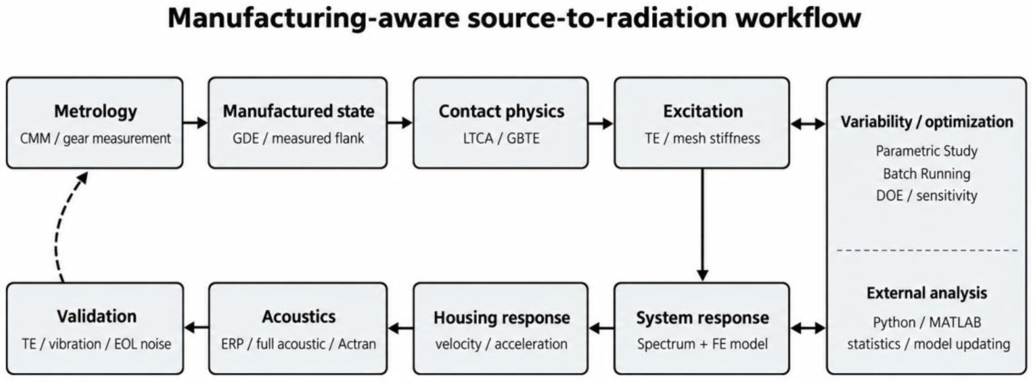
Table 2.
Functional role of the principal Romax environments in the manufacturing-aware NVH workflow.
Table 2.
Functional role of the principal Romax environments in the manufacturing-aware NVH workflow.
| Research layer | Romax environment | Primary input | Primary output | Evidence basis |
| Measured tooth flank / CMM-derived data | Spectrum; or Enduro + detailed gear contact option | GDE / measured microgeometry | Profile, lead and pitch deviations; designed vs measured comparison | 2025.1 Help; GDE release documentation |
| Loaded tooth contact analysis | Spectrum / Enduro | Nominal or measured flank; load; alignment | Contact patch, load distribution, contact stress, TE, stiffness | 2025.1 Help; 2022.1–2025.1 releases |
| System TE / excitation | Spectrum | System deflection + microgeometry | Linear TE, tilt/misalignment TE, mesh stiffness, harmonics | 2025.1 GBTE |
| System dynamics | Spectrum | Gear / EM excitations; FE components | Bearing forces, vibration response, ODS / harmonic response | 2025.1 Help |
| Structural acoustics | Spectrum + Acoustic Analysis / Actran | Housing surface response | ERP, sound power / pressure depending on acoustic workflow | 2022 ERP; acoustic/Actran help |
| Variability / optimization | Variability and Optimization + task-specific product | Geometry, preload, misalignment, duty-cycle variables | DOE / parametric response, optimized candidates, automated outputs | Parametric Study and Batch Running |
| External MBD / vehicle integration | Dynamic Fusion / substructure export | Romax model or condensed subsystem | Adams/Modelica model; MSC Nastran/OptiStruct subsystem | Dynamic Fusion; 2023.1 substructure export |
Table 3.
Implementation stages, outputs and research controls in the proposed workflow.
| Stage | Environment | Output | Research control |
| 1. Metrology | CMM / gear measurement | Tooth-resolved profile, lead, pitch or topography data | Retain tooth and flank identity where possible. |
| 2. Data translation | GDE / measured microgeometry import | Romax measured flank representation | Document exactly which measured quantities are transferred. |
| 3. Contact state | LTCA / GBTE | Contact patch, pressure, load distribution, mesh stiffness, linear and tilt TE | Use measured and nominal cases for paired comparison. |
| 4. Variability screening | Parametric Study / Batch Running | Sensitivity of contact and TE indicators | Screen many cases before expensive dynamic/acoustic runs. |
| 5. Dynamic propagation | Spectrum system dynamics + FE components | Bearing forces, housing velocity/acceleration, harmonic response | Include bearing, shaft and housing flexibility consistently. |
| 6. Acoustic screening | ERP | Fast radiation-oriented ranking | Use for comparison, not as absolute SPL validation. |
| 7. Detailed acoustics | Acoustic Analysis / Actran | Sound power / pressure field depending on setup | Run selected representative cases. |
| 8. Experimental correlation | TE rig, accelerometers, microphones, EOL order data | Model–measurement residuals and trend validation | External measurement and post-processing required. |
| 9. Model updating / inference | Python/MATLAB + rerun | Updated uncertain parameters; statistical interpretation | Not a documented one-click Romax workflow. |
Table 4.
Research questions, required inputs and falsifiable validation targets.
| Research question | Required input | Romax stage | Validation data | Feasibility |
| How does tooth-resolved measured microgeometry, when available, change TE harmonic topology? | Tooth-resolved measured/design microgeometry with verified tooth identity | LTCA / GBTE harmonic output | TE measurement; order tracking | High |
| Which manufacturing deviations dominate NVH variability? | Measured/tolerance distributions | Parametric study + sensitivity analysis | EOL vibration/acoustic spread | High |
| How does misalignment alter contact and vibration? | Bearing/shaft position, preload, housing deflection | Static analysis + GBTE + dynamics | Rig alignment/preload variation | High |
| Can matched measured flank geometry explain unit-specific EOL outliers better than the nominal model? | Unit-specific gear measurement + unit-specific EOL data | Measured geometry → GBTE → response | Matched component IDs | Medium–high; data linkage critical |
| How does housing flexibility transform identical mesh excitation? | Validated FE housing variants | System dynamics + ERP/acoustics | Modal test + vibration/noise | High |
| Can wear be propagated to NVH? | Updated worn geometry from measurement or external wear model | Re-import geometry + rerun LTCA/GBTE/NVH | Repeated CMM + test | Medium; manual/scripted loop |
| Can a surrogate model replace expensive acoustic runs? | DOE outputs from Romax | External ML / response surface | Hold-out high-fidelity runs | High if validation is rigorous |
| Does tooth-resolved measured geometry outperform tooth-averaged geometry for predicting TE sidebands? | Matched tooth-level metrology; averaged comparator | Measured microgeometry → GBTE | TE/order tracking | High; directly falsifiable |
| Does ERP preserve the same manufacturing-state ranking as full acoustics? | Selected geometry states + validated FE housing | Dynamic response → ERP + full acoustics | Microphone / sound-power data | Medium–high; frequency dependent |
Table 5.
Peer-reviewed evidence matrix for the proposed workflow. Romax-specific studies demonstrate selected links; independent studies provide physical and validation evidence.
Table 5.
Peer-reviewed evidence matrix for the proposed workflow. Romax-specific studies demonstrate selected links; independent studies provide physical and validation evidence.
| Study | Tool context | Evidence relevant to this workflow | Use in the present methodology |
| Zhang et al. (2020) [25] | Romax | 3D parametric contact model; LTCA; TE sensitivity to tooth modification | Supports parametric contact/TE studies in Romax |
| de Walque & Jamaluddin (2023) [17] | Romax Spectrum + Actran | Structural e-powertrain response coupled to vehicle acoustic radiation | Supports external acoustic continuation of Spectrum results |
| Huang et al. (2023) [18] | Romax + Actran | TE, rigid-flexible response, vibration and acoustic optimization | Supports integrated excitation-response-acoustic workflow |
| Yang et al. (2026) [19] | Romax + tests | Reducer model, rigid-flexible electric drive, microgeometry optimization and vehicle verification | Strong recent Romax-specific validation example |
| Im et al. (2025) [3] | Independent LTCA + STE test | Measured profile errors propagated to TE and experimentally checked | Supports measured-geometry-to-TE validation logic |
| Najib et al. (2024) [4] | Numerical + experiments | Manufacturing uncertainty changes STE and dynamic response | Supports variability and uncertainty treatment |
| Wang et al. (2025) [24] | Independent LTCA | Surface waviness changes contact and TE characteristics | Supports waviness-resolved geometry treatment |
| Lahoti et al. (2021) [26] | Simulation + manufactured parts + test | TE/contact optimization correlated to >6 dB whine improvement in most cases | Supports design-change-to-test closure |
| Horvath & Zelei (2025) [22] | Gear-NVH digital-twin review | Identifies fragmented metrology/simulation/test integration and validation gaps | Defines the field-level gap; present paper operationalizes one version-verified Romax path |
| Lei et al. (2021) [21] | Digital twin + NLTCA | Manufacturing/grinding state linked to loaded contact performance | Supports manufacturing-state digital-twin logic, but not full NVH propagation |
| Liang et al. (2023) [16] | Measured error points + contact/FE + rolling test | Measured tooth-surface deviations propagated to contact pattern and TE with experimental check | Supports measured-geometry-to-contact/TE validation |
| Lee & Park (2023) [20] | Inspection data + noise bench + ML | Direct data-driven prediction of gear-whine noise from gear inspection variables | Provides a complementary statistical branch and highlights the need to distinguish correlation from physics propagation |
| Tao et al. (2023) [27] | Manufacturing-error model + NVH test | Pitch, helix-tilt and runout errors alter TE harmonics and transmission vibration response | Supports propagation of manufacturing errors from mesh excitation to system response |
| Palermo et al. (2018) [9] | TE measurement on EV gearbox | Direct TE measurement validated as an NVH indicator and linked to microgeometry development | Provides a source-level experimental gate for GBTE/TE validation |
| Su et al. (2024) [10] | EOL bench + vehicle measurements | EOL vibration correlated with vehicle vibration/acoustic sound-quality outcomes across production units | Provides an independent production-response validation endpoint |
Disclaimer/Publisher’s Note: The statements, opinions and data contained in all publications are solely those of the individual author(s) and contributor(s) and not of MDPI and/or the editor(s). MDPI and/or the editor(s) disclaim responsibility for any injury to people or property resulting from any ideas, methods, instructions or products referred to in the content. |
© 2026 by the authors. Licensee MDPI, Basel, Switzerland. This article is an open access article distributed under the terms and conditions of the Creative Commons Attribution (CC BY) license (http://creativecommons.org/licenses/by/4.0/).
Copyright: This open access article is published under a Creative Commons CC BY 4.0 license, which permit the free download, distribution, and reuse, provided that the author and preprint are cited in any reuse.