
Submitted:
29 August 2026
Posted:
31 August 2026
You are already at the latest version
Abstract
Sucker rods operate under long-term cyclic loading while exposed to corrosive produced fluids, making corrosion–fatigue damage a major integrity concern. This study examined produced-fluid samples from 16 wells with sucker-rod failures and 16 corresponding failed rods from a Daqing oil production plant using ionic-composition analysis, SEM/EDS, bulk chemical analysis, metallography, axial tensile tests, exploratory fatigue tests, and field load analysis. The fluids were HCO₃⁻-dominated, with average HCO₃⁻, Cl⁻, and SO₄²⁻ concentrations of 345.7, 0.129, and 2.55 mg/L, respectively. Representative fracture surfaces showed corrosion pits, corrosion products, secondary cracks, and lamellar or step-like morphologies, while corroded microregions were enriched in O and contained detectable Cl and S. Local discontinuities, including decarburization, inclusions, and scratches, were also observed. Residual tensile strength varied substantially with service history, and exploratory fatigue results showed considerable scatter. The actual field fracture location did not coincide with the maximum nominal axial stress. The combined evidence supports a representative sequence of localized corrosion and pit formation, crack-susceptible region development, microcrack initiation, cyclic crack propagation, crack coalescence, loss of effective load-bearing area, and final rapid fracture.
Keywords:
sucker rod
; corrosion fatigue
; corrosion pit
; crack initiation
; crack propagation
; cyclic loading
; failure analysis
1. Introduction
Rod-pumped artificial lift remains widely used in onshore oilfields, particularly mature fields, because of its established design, broad applicability, and mature maintenance practices. During service, sucker rods are subjected to long-term reciprocating cyclic loads while continuously exposed to water-bearing produced fluids, corrosive ions, and complex rod–tubing contact conditions. Their reliability is therefore governed by the combined effects of corrosion, fatigue, wear, and local stress concentration [1,2,3,4,5,6]. Sucker-rod fracture can cause unplanned well shutdowns and workover operations, increase maintenance costs, and reduce production uptime. Identifying the dominant progression from surface damage to crack growth and final fracture is therefore essential for improving the long-term reliability of rod-pumping systems [7,8,9,10,11,12].
Previous studies have identified fatigue and corrosion fatigue as major failure modes of steel sucker rods. Cl⁻, HCO₃⁻, and sulfur-containing species in wellbore fluids can participate in electrochemical reactions at steel surfaces, while corrosion pits and other surface discontinuities can act as local stress concentrators under cyclic loading [13,14,15,16,17,18,19,20]. Microstructure, nonmetallic inclusions, surface decarburization, machining or service-induced scratches, and pre-existing corrosion damage may further increase susceptibility to crack initiation. Sucker-rod loading is inherently cyclic, and the stress distribution along the rod string is affected by rod-diameter combinations, well depth, pump load, and operating conditions. Field rod failures therefore rarely arise from insufficient material strength or corrosion alone; rather, damage accumulation must be considered in terms of the interacting effects of environment, material condition, and loading [21]. Corrosion-fatigue studies further show that corrosive media can markedly alter fatigue life under cyclic loading. Consequently, the service safety of downhole components cannot be assessed reliably from the fatigue behavior of smooth specimens tested in air alone [22,23,24,25].
Despite extensive research on sucker-rod failure mechanisms, fatigue life, and fracture prediction, two important limitations remain. First, many failure analyses examine only one or a few representative failed rods and infer failure causes from fracture morphology, material defects, or individual operating factors. Although such analyses can identify local anomalies, they cannot readily determine whether field samples with different service durations, rod diameters, and rod-body conditions share a common damage pattern [26]. Second, fatigue-life prediction and numerical models generally require prescribed material parameters, defect sizes, and loading boundary conditions. In service, however, corrosion pits, local microstructural condition, and actual loads are coupled, so the cyclic response of laboratory smooth specimens cannot be directly equated with the behavior of full-size rods containing service-induced damage [27]. A multi-source evidence chain is therefore needed to link the wellbore-fluid environment with material condition, corrosion microregions, fracture-surface features, residual mechanical properties, and field rod-string loading. Such an approach can reduce the risk of attributing complex field failures to a single inspection indicator [28,29,30,31].
To address these limitations, this study investigated 16 producing wells with sucker-rod failures in the Daqing Oilfield and the corresponding failed rods. The dataset covered nominal rod diameters of 19, 22, and 25 mm and included new, long-term service-aged, and refurbished rods [32,33,34,35,36]. The working hypothesis was that field sucker-rod fracture is not controlled by a single material-composition abnormality or nominal load level. Instead, local surface damage induced by the wellbore environment and local material discontinuities jointly increase crack-initiation susceptibility and promote damage evolution under long-term cyclic loading [37,38,39,40,41,42,43].
To test this hypothesis, 16 failed sucker rods and the corresponding produced fluids from rod-failure wells in a Daqing oilfield were examined. The investigation focused on corrosion pits, cracks, and service-condition differences commonly observed in field failures and followed the sequence “service-medium background–initial material and surface condition–local fracture-surface characteristics–residual mechanical properties–cyclic response–field loading.” Produced-fluid analysis was first used to characterize the common corrosive environment. Metallography, SEM/EDS, and bulk chemical-composition analysis were then used to identify local defects and evidence of environmental interaction. Finally, axial tensile tests, exploratory fatigue tests, and load analysis of a representative sucker-rod string were integrated to construct a multi-source “environment–defect–property–crack–fracture” evidence chain. This framework was used to characterize the representative evolution of corrosion-fatigue damage and to support failure diagnosis and integrity management of in-service sucker-rod strings [43,44,45,46,47,48,49,50].
The following sections describe the field-failure samples, produced-fluid analysis, and material and mechanical testing methods. The microstructure, fracture-surface features, local chemical characteristics, and mechanical responses of rods with different service histories are then compared. The relationship between environmental damage and cyclic loading is discussed using the load distribution of a representative rod string, and a damage-evolution mechanism is subsequently proposed for the present set of field-failure samples.
2. Materials and Methods
2.1. Sample Sources and Study Design
Samples were obtained from 16 producing wells with sucker-rod failures at an oil production plant in Daqing and comprised 16 produced-fluid samples and 16 corresponding failed sucker rods. The rods had nominal diameters of 19, 22, and 25 mm and included new, long-term service-aged, and refurbished rods. Known service durations ranged from 0.2 to 22.8 years.
The experimental program was structured around the progressive assessment of surface corrosion, local cracking, and service-condition differences rather than as a set of independent tests. Produced-fluid analysis characterized the common service-medium background of the 16 rod-failure wells. Metallography and bulk chemical-composition analysis assessed the microstructure, decarburization layers, inclusions, and overall composition for common abnormalities. SEM/EDS was used to identify corrosion pits, secondary cracks, and local elemental enrichment on fracture surfaces. Axial tensile and exploratory fatigue tests evaluated the residual load-bearing capacity and cyclic response of service-exposed material. Finally, nominal-stress analysis of a representative sucker-rod string linked the laboratory observations to field load locations. The results were integrated according to the sequence “environment–material condition–local damage–mechanical response–field loading,” thereby avoiding attribution of failure to any single test result.
Representative samples were selected by considering rod diameter, service duration, rod-body condition, and fracture-surface characteristics. Rods with nominal diameters of 19, 22, and 25 mm were included, together with short-term service, long-term service, used, and refurbished conditions. Representative images illustrate typical features, whereas the complete test dataset was used to assess overall trends.

Table 1.
Information and Service Conditions of the Failed Sucker-Rod Samples.
| No. | Diameter (mm) | Condition | Well | Service (years) | Remarks |
|---|---|---|---|---|---|
| 1 | 19 | New rod (HY grade) | XF8-1-518 | 0.86 | New-rod reference sample |
| 2 | 19 | Used rod | X11-2-B221 | 22.8 | Long-term service |
| 3 | 19 | Used rod | X11-3-B326 | 4.3 | Insufficient fluid supply |
| 4 | 22 | New rod | X10-3-B2422 | 3.8 | New-rod sample |
| 5 | 22 | New rod (Longxing) | X8-D3-320 | 9.1 | New rod/batch difference |
| 6 | 22 | Used rod | X9-D2-149 | ≥5.6 | Representative mid-string fracture well |
| 7 | 22 | Refurbished rod | X13-D1-219 | 5.6 | Refurbished-rod sample |
| 8 | 22 | Used rod (high stress) | X9-D3-138 | 2.8 | High alternating load |
| 9 | 22 | Unknown | X12-2-B28 | 3.2 | Risk of eccentric wear |
| 10 | 22 | Used rod | X9-D3-F336 | Unknown | Eccentric wear/insufficient centralizers |
| 11 | 22 | Used rod | X9-3-144 | 3.9 | Short-term service |
| 12 | 22 | Used rod | X10-1-B40 | 6.6 | Insufficient fluid supply |
| 13 | 25 | New rod | X8-2-E222 | 0.2 | Early failure |
| 14 | 25 | Used rod | X10-5-SB3622 | 5.5 | Intermediate service duration |
| 15 | 25 | Used rod | X9-D2-140 | 12.5 | High load/insufficient fluid supply |
| 16 | 25 | Used rod | X8-2-B183 | 17.9 | Long-term service |
2.2. Produced-Fluid Composition Testing
Produced-fluid analysis was performed to characterize the common corrosive wellbore environment experienced by the failed sucker rods and to compare the bulk-fluid chemistry with the local detection of O, Cl, S, and other elements by fracture-surface EDS. Samples from the 16 rod-failure wells were first subjected to sand filtration and vacuum filtration to remove insoluble inorganic particles and suspended matter. Cl⁻ and SO₄²⁻ concentrations were measured by ion chromatography. After calibration with standard solutions, 2 mL of filtrate was injected for each analysis. HCO₃⁻ and CO₃²⁻ concentrations were determined by potentiometric titration using 5 mL of filtrate per test.
Fe³⁺ was measured by the 1,10-phenanthroline colorimetric method using visible spectrophotometry. A 5 mL aliquot of filtrate was transferred to a 50 mL volumetric flask, followed sequentially by hydroxylamine hydrochloride solution, sodium acetate–acetic acid buffer, and 1,10-phenanthroline solution. After color development and dilution to volume, absorbance was measured with a Model 722 visible spectrophotometer, and the Fe³⁺ concentration was obtained from the calibration curve.
2.3. SEM/EDS Characterization of Fracture Surfaces and Rod Bodies
SEM and EDS analyses were performed on the fracture surfaces and corresponding rod-body regions of all 16 failed sucker rods. Specimens approximately 1 cm long were sectioned near the fracture. After removal of loose surface particles, the specimens were subjected to three low-power ultrasonic-cleaning cycles in petroleum ether and dried for 6 h after each cycle. They were subsequently rinsed with absolute ethanol, dried, and stored until analysis.
SEM observations were conducted at an accelerating voltage of 20 kV. Fracture surfaces were first examined at low magnification to identify potential crack-origin regions and were then examined at higher magnification to characterize corrosion pits, secondary cracks, and step-like or lamellar features. EDS measurements were obtained from selected fracture-surface corrosion-product regions, crack-adjacent regions, and rod-body matrix regions away from the fracture. Elemental mass and atomic fractions were recorded. Because no unfailed rod was available that matched each failed rod by well, batch, and service history, the rod-body matrix served only as an internal reference within the same specimen. This comparison was used to assess local differences in O, Cl, S, Fe, C, and other elements between fracture-surface and matrix microregions.
2.4. Chemical Composition Analysis
Bulk chemical compositions of the rod-body matrix and fracture-adjacent regions were measured by spark optical emission spectroscopy. After machining, each test surface was mounted on the sample stage. The instrument was standardized using a reference material of the corresponding grade, and calibration was verified with a control sample. Each surface was excited 3–5 times to determine C, Si, Mn, Cr, Mo, P, S, and other elements, and the mean value was reported. Spark optical emission spectroscopy was used to characterize the bulk alloy composition of the rod matrix, whereas EDS characterized local elemental distributions in selected microregions. The two techniques therefore provide complementary information on bulk matrix composition and local fracture-surface chemistry.
2.5. Metallographic Examination
Metallographic specimens were sectioned from fracture-adjacent and rod-body regions and prepared by wire cutting, mounting, grinding, polishing, and etching. The specimens were progressively ground with 180#–1200# abrasive papers, polished with W1.5 and W1.0 diamond pastes, and etched with a 2–4 vol.% nitric acid–ethanol solution.
The matrix and near-surface microstructures were examined by optical metallography. Grain size, nonmetallic inclusions, and surface decarburization were evaluated. XF8-1-518, X8-D3-320, and X8-2-E222 were selected as representative microstructural samples for the 19, 22, and 25 mm rods, respectively.
2.6. Axial Tensile Testing
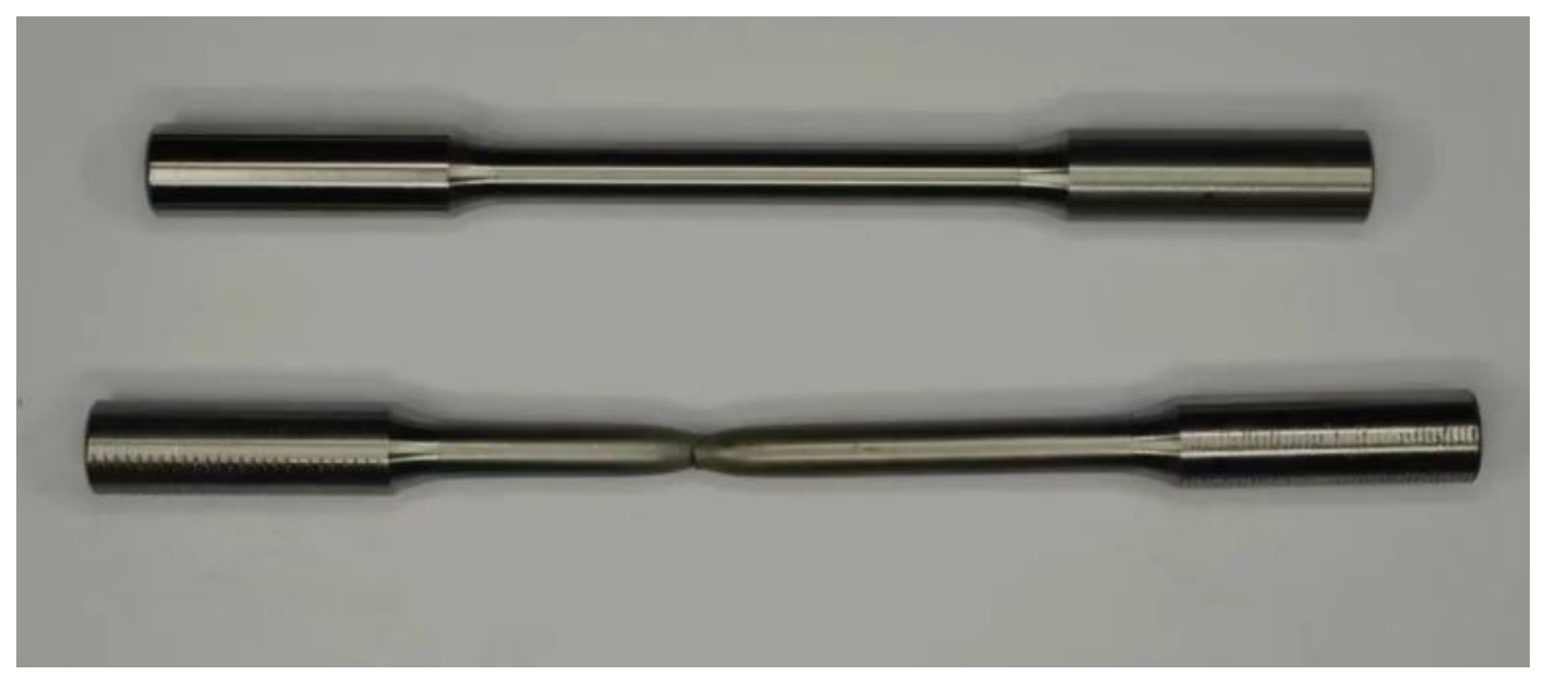
Room-temperature axial tensile tests were conducted using a digital-display hydraulic universal testing machine. Smooth round-bar specimens with a diameter of 6 mm and a gauge length of 30 mm were machined from the failed rods, corresponding to a nominal initial cross-sectional area of 28.26 mm². Before testing, the specimen diameter and initial gauge length were measured, and each specimen was aligned and clamped.
Each specimen was loaded continuously to fracture while force–displacement and engineering stress–strain data were recorded. Tensile strength was calculated as follows:
where σb is the tensile strength, Fmax is the maximum tensile load, and A0 is the initial cross-sectional area.
σᵦ = Fₘₐₓ / A₀
Figure 1.
Digital-Display Hydraulic Universal Testing Machine Used for the Tensile Tests.
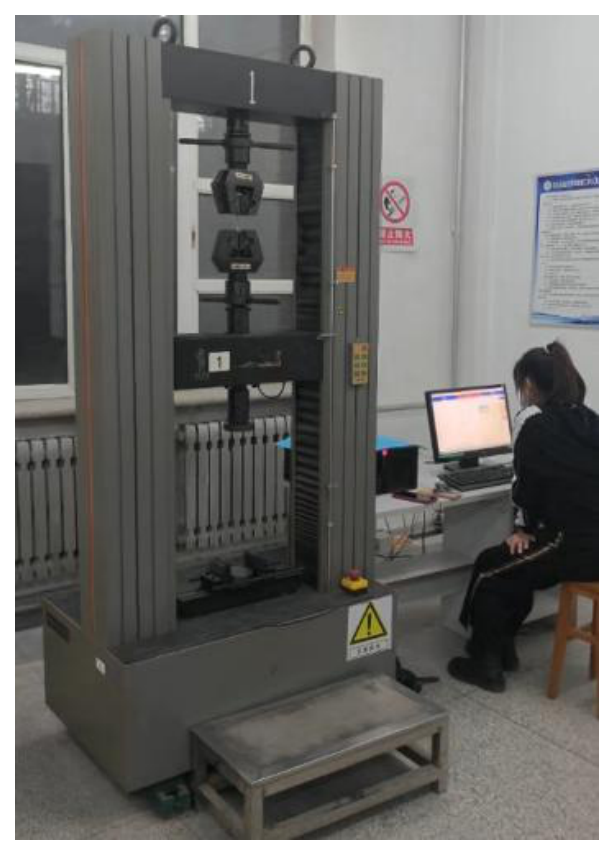
Figure 2.
Axial Tensile Specimen Machined from a Sucker Rod.
2.7. Axial Fatigue Testing and Sucker-Rod-String Load Analysis
Room-temperature exploratory fatigue tests were conducted using an axial fatigue testing machine. Smooth cylindrical specimens with a nominal diameter of 10 mm were machined from source rods with diameters of 19, 22, and 25 mm. Before testing, specimen dimensions were measured, and the specimens were cleaned with an organic solvent, oven-dried, and clamped. The upper and lower grips were adjusted to ensure alignment and minimize eccentric loading.
Sinusoidal cyclic loading was applied at a stress ratio of R = 0.1, a frequency of 100–500 Hz, and stress amplitudes of 325, 357.5, and 390 MPa. The stress ratio was defined as:
R = σₘᵢₙ / σₘₐₓ
Testing stopped automatically when the prescribed number of cycles was reached or the specimen fractured. The number of cycles, load response, and fracture location were recorded.
Well X9-D2-149 was selected for calculation of nominal axial stresses along the sucker-rod string. The pump depth was 851.39 m, and the string comprised 877.98 m of 22 mm rods and 9.14 m of 19 mm rods. The maximum and minimum surface loads were 63.16 and 14.95 kN, respectively. The actual fracture occurred near the middle of the 82nd rod at a depth of approximately 681.04 m. Maximum, minimum, mean, and alternating stresses at representative locations were calculated from the cross-sectional areas of rods with different diameters.
where A is the rod cross-sectional area, σm is the mean stress, and σa is the alternating stress amplitude. The calculation represents a quasi-static nominal axial-stress analysis and does not account for longitudinal rod-string vibration, well deviation, rod–tubing contact, bending, friction, pump-valve impact, or local stress concentration caused by corrosion pits. It was therefore used primarily to compare the depth-wise distribution of nominal stress with the actual fracture location.
σₘₐₓ,ₘᵢₙ = Fₘₐₓ,ₘᵢₙ / A
σₘ = (σₘₐₓ + σₘᵢₙ) / 2
σₐ = (σₘₐₓ − σₘᵢₙ) / 2
3. Results and Discussion
3.1. Composition and Representativeness of the Failed Samples
The dataset comprised 16 failed sucker rods with nominal diameters of 19, 22, and 25 mm, including 3, 9, and 4 rods of each diameter, respectively. Known service durations ranged from 0.2 to 22.8 years, and the samples included new, long-term service-aged, and refurbished rods with diverse field operating histories (Figure 3). Failures were not concentrated at a specific rod diameter and did not increase monotonically with service duration. Accordingly, subsequent microstructural, fractographic, and mechanical analyses used a “comprehensive testing with representative presentation” approach. Representative samples were selected by jointly considering rod diameter, service duration, rod-body condition, and damage characteristics.
The marked heterogeneity in rod diameter and service history indicates that the field failures cannot be characterized by a single diameter or service-duration threshold. The dataset included rods with less than one year of service as well as used rods with more than ten years of service. Service duration alone is therefore insufficient for assessing fracture risk. Subsequent analyses focused on identifying common signatures of environmental interaction, local damage morphology, and mechanical response across the different samples.
3.2. Metallographic Microstructure and Local Defect Characteristics
The failed sucker rods generally exhibited microstructures typical of quenched-and-tempered alloy steels. Tempered sorbite predominated in most samples, while bainite, martensite, pearlite, or small amounts of ferrite were observed in some specimens. Grain-size ratings were approximately 7–10, with representative samples near Grade 9. Nonmetallic-inclusion ratings were approximately 1.5–2.5 and consisted mainly of oxides and globular oxides. Surface decarburization-layer thicknesses ranged from approximately 0.02 to 0.12 mm. Representative metallographic microstructures of the 19, 22, and 25 mm rods are shown in Figure 4; results for the remaining samples were included in the overall assessment.
No matrix-microstructure abnormality was observed that could consistently explain the failures across the entire batch. However, some rods exhibited near-surface decarburization layers, inclusions, and machining- or service-induced surface traces. The rods were therefore characterized primarily by conventional quenched-and-tempered microstructures with localized microstructural or surface discontinuities. Because tempered sorbite and relatively fine grains formed the dominant microstructural background, matrix microstructure alone cannot explain the fracture behavior of rods with different service histories.
Surface decarburization, inclusion–matrix interfaces, and machining- or service-induced scratches are localized discontinuities that may alter the local stress and damage state. When considered together with the corrosion pits and cracks observed on the fracture surfaces, these features are more appropriately interpreted as factors that may increase crack-initiation susceptibility. Without direct spatial correspondence between a specific discontinuity and a crack origin, however, none can be identified independently as the direct cause of fracture.
3.3. Fracture-Surface SEM Morphology and EDS Characteristics
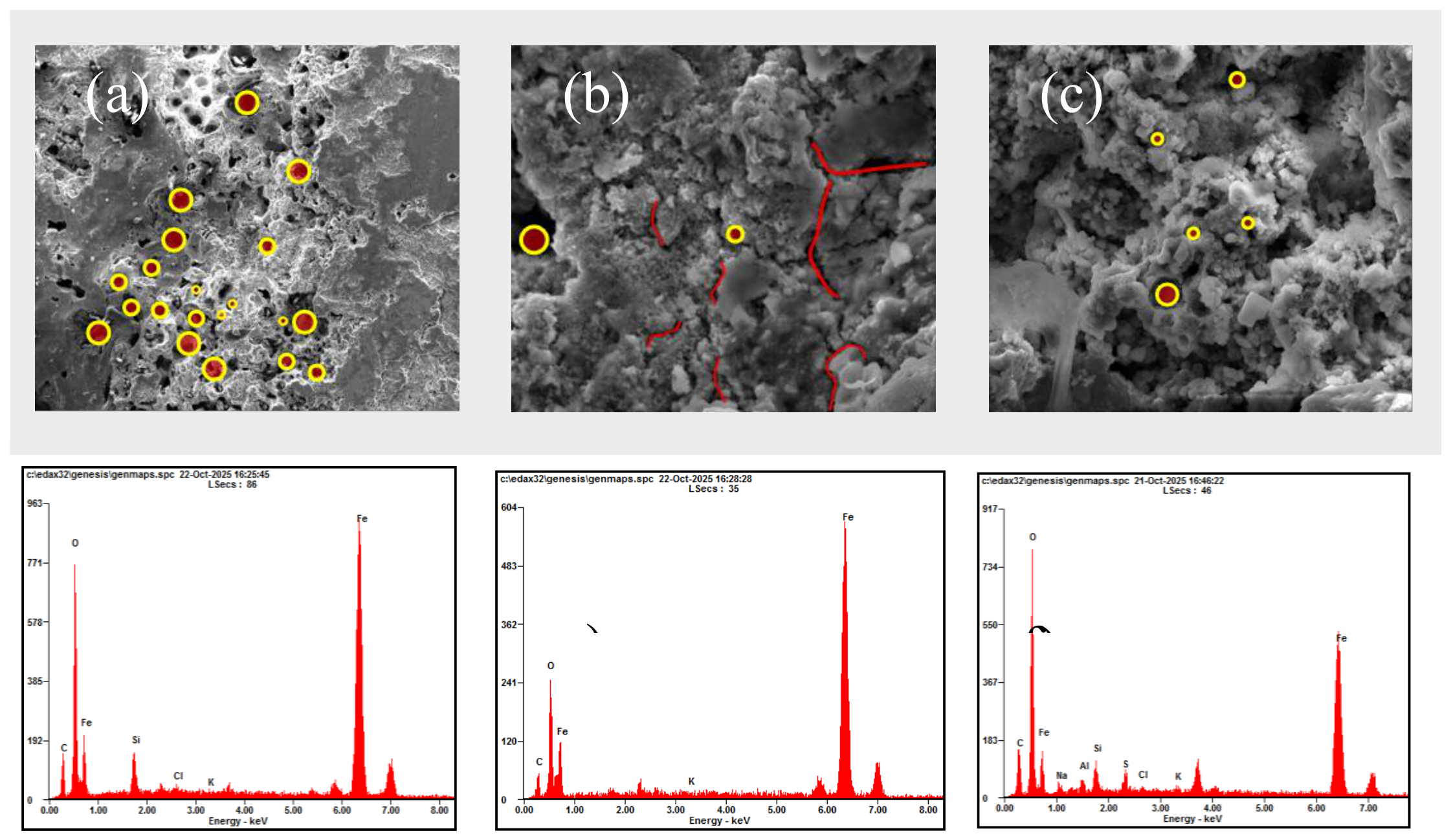
Fracture surfaces from rods with different service histories exhibited several recurring local damage features. Because of the number of samples, rods representing different diameters, service durations, and failure characteristics were selected for detailed presentation, while the remaining SEM/EDS results were included in the overall assessment. No unfailed rods matched to each failed rod by well, batch, and service period were available as independent controls. Quantitative comparisons between failed and normal rods were therefore not performed; instead, EDS results from corroded fracture-surface microregions were compared with matrix microregions away from the fracture within the same failed rod. X11-2-B221, after 22.8 years of service, exhibited numerous cavities and corrosion pits, step-like regions, and multiple secondary cracks. X9-D2-140, after 12.5 years of service, showed extensive corrosion-product coverage, sharp-edged pits, and local cracks. X8-2-E222 had been in service for only 0.2 years, yet its fracture surface also contained porous corrosion products, local pitting, and secondary cracks. Corrosion pits and cracks were likewise observed at the mid-string fracture location of well X9-D2-149.
EDS analysis revealed clear local compositional differences between selected corroded fracture-surface microregions and matrix microregions from the same failed rods. For X11-2-B221, the fracture-surface microregion contained 20.15 wt.% O and 0.41 wt.% Cl. For X9-D2-149, O, S, Cl, and Fe contents were 20.35, 1.15, 1.90, and 68.10 wt.%, respectively. For X9-D2-140, O, S, and Cl contents were 28.35, 1.70, and 0.35 wt.%, respectively, whereas the corresponding values for X8-2-E222 were 19.25, 1.34, and 0.61 wt.%. In contrast, the selected rod-body matrix microregions were predominantly Fe. These comparisons indicate stronger oxidation and local enrichment of environment-related elements on the fracture surfaces but do not constitute a control comparison with unfailed rods.
Table 2.
Fracture Morphologies and EDS Microregion Compositions of Representative Failed Sucker Rods.
Table 2.
Fracture Morphologies and EDS Microregion Compositions of Representative Failed Sucker Rods.
| Sample | Condition / Service | Fracture/Crack Morphology | EDS (wt.%) |
|---|---|---|---|
| X11-2-B221 | 19 mm used rod; 22.8 years | Dense corrosion pits; cleavage steps; secondary cracks | O 20.15;Cl 0.41;Fe 69.76 |
| X9-D2-149 | 22 mm used rod; ≥5.6 years | Corrosion pits and cracks; actual fracture in the middle section | O 20.35;S 1.15;Cl 1.90;Fe 68.10 |
| X9-D2-140 | 25 mm used rod; 12.5 years | Corrosion-product coverage; sharp-edged pits; local cracks | O 28.35;S 1.70;Cl 0.35;Fe 53.63 |
| X8-2-E222 | 25 mm new rod; 0.2 years | Porous corrosion products; secondary cracks; local pitting | O 19.25;S 1.34;Cl 0.61;Fe 71.81 |
Figure 5.
SEM Morphologies and EDS Spectra of Representative Failed Sucker-Rod Fracture Surfaces: (a,b) overall fracture surface and local pitting/cracking of X11-2-B221; (c) corrosion-pit region of X9-D2-140; (d) secondary-crack region of X8-2-E222; (e,f) EDS spectra of the fracture surface and matrix of X8-2-E222. Yellow circles indicate representative corrosion pits or cavities, and red lines indicate visible secondary cracks.
Figure 5.
SEM Morphologies and EDS Spectra of Representative Failed Sucker-Rod Fracture Surfaces: (a,b) overall fracture surface and local pitting/cracking of X11-2-B221; (c) corrosion-pit region of X9-D2-140; (d) secondary-crack region of X8-2-E222; (e,f) EDS spectra of the fracture surface and matrix of X8-2-E222. Yellow circles indicate representative corrosion pits or cavities, and red lines indicate visible secondary cracks.
3.4. Ionic Composition of Produced Fluids and Its Relationship with Fracture-Surface Elements
The produced fluids from the 16 rod-failure wells had generally similar major-ion compositions. HCO₃⁻ concentrations ranged from 338 to 351 mg/L, with an average of 345.7 mg/L. SO₄²⁻ concentrations ranged from 2.1 to 2.9 mg/L, with an average of 2.55 mg/L, while Cl⁻ concentrations ranged from 0.09 to 0.16 mg/L, with an average of 0.129 mg/L. CO₃²⁻ and OH⁻ were not detected, and the measured iron-ion concentration was below 0.4 mg/L (Table 3 and Figure 6). The relatively narrow concentration ranges indicate a broadly similar ionic background among the wells, with HCO₃⁻ as the dominant anion. Representative corroded fracture-surface microregions also contained relatively high O contents and detectable Cl and S.
Produced-fluid analysis established the common wellbore-fluid background for the failed rods. Because major-ion concentrations varied only slightly among the 16 wells, the bulk-fluid data could not distinguish the severity of rod damage among wells or support a failure-risk ranking. The presence of HCO₃⁻, Cl⁻, and SO₄²⁻ in the produced fluids, together with local O, Cl, and S detected on the fracture surfaces, is consistent with environmental involvement in the observed local damage.
Bulk produced-fluid chemistry, however, cannot directly represent the local chemical conditions within corrosion pits, beneath deposits, or at crack tips. The produced-fluid data should therefore be interpreted as environmental boundary conditions rather than as a stand-alone explanation for differences in damage severity. Material condition, fracture-surface characteristics, and load history must also be considered.
3.5. Chemical Composition of the Rod-Body Matrix
Bulk chemical-composition analysis showed that all failed rods consisted primarily of Fe and the expected alloying elements. Although the Cr, Mo, and other major alloying-element contents varied among samples, no consistent abnormal deviation was observed across the batch. The available data therefore do not indicate a common bulk-composition anomaly that could account for the failure of all 16 rods.
In contrast to the bulk matrix composition, environment-related elements such as O, Cl, and S were detected locally on fracture surfaces. Bulk rod composition and local fracture-surface chemistry therefore describe different material scales. Because the major alloying elements showed no consistent deviation, the failures cannot be uniformly attributed to a common raw-material composition problem. Local elemental enrichment should instead be interpreted together with the corrosion morphology and other test results.
3.6. Tensile Properties and Strength Degradation Characteristics
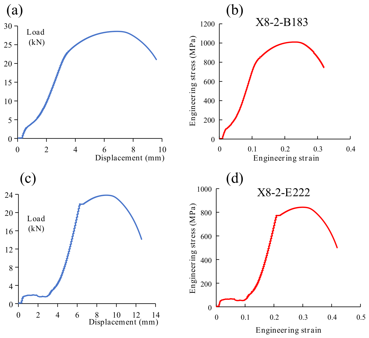
For a given material, increasing rod diameter increases the overall axial load-bearing capacity but does not necessarily increase the intrinsic tensile strength. The measured tensile strengths varied among rods with different dimensions and service histories, and long-term service-aged rods generally exhibited varying degrees of mechanical-property degradation. The reported strength-degradation ranges for used 19, 22, and 25 mm rods were 15.74–20.80%, 14.75–27.77%, and 8.69–25.71%, respectively. All failed rods were subjected to axial tensile testing; Table 4 presents selected representative results because the complete dataset is extensive.
The presence of HCO₃⁻, Cl⁻, and sulfur-containing species in the produced fluids indicates an environment capable of supporting localized corrosion. Corrosion-related section loss, surface decarburization, and other local defects can reduce the effective load-bearing area and create sites that are more susceptible to crack initiation under cyclic loading.
The 22 mm used rod X9-D3-138 had been in service for only 2.8 years, yet its reported strength-degradation rate reached 24.32%, exceeding that of X9-D2-149 despite the latter's longer service history. This comparison suggests that service duration and material degradation are not related in a simple one-to-one manner and that substantial degradation can also occur over shorter service periods under high loads or unfavorable operating conditions. The refurbished rod X13-D1-219 exhibited a reported degradation rate of 13.25%. Surface refurbishment may improve appearance and local surface condition but may not remove pre-existing internal or fatigue damage. Overall, the observed mechanical-property degradation is consistent with the combined influence of initial material condition, corrosive exposure, service duration, and load history.
Figure 7.
Tensile Force–Displacement and Engineering Stress–Strain Curves of Representative Sucker Rods: (a) X8-2-B183; (b) X8-2-E222.
Figure 7.
Tensile Force–Displacement and Engineering Stress–Strain Curves of Representative Sucker Rods: (a) X8-2-B183; (b) X8-2-E222.
3.7. Exploratory Fatigue Response and Loading Characteristics of a Representative Sucker-Rod String
Representative exploratory axial fatigue results were compared for specimens machined from 19, 22, and 25 mm source rods and tested at the same stress amplitudes; the complete fatigue dataset is not listed individually. All groups fractured at stress amplitudes of 357.5 and 390 MPa, whereas no specimen fractured at 325 MPa within the prescribed number of cycles. At 390 MPa, the measured lives of specimens from the 19, 22, and 25 mm rods were 75,234, 82,378, and 91,023 cycles, respectively. At 357.5 MPa, the corresponding lives were 48,986, 50,122, and 55,846 cycles, respectively.
Within each stress-amplitude level, the measured fatigue lives increased from the 19 mm source rod to the 25 mm source rod. However, the measured lives at 390 MPa were higher than those at 357.5 MPa for all three source-rod diameters. The present exploratory dataset therefore does not exhibit a conventional monotonic S–N relationship and should not be used to establish a fatigue limit or a definitive stress–life trend. At 325 MPa, all three specimens reached the prescribed run-out condition without fracture. These results indicate substantial scatter in the cyclic response of service-exposed material and emphasize the need for additional replicate tests before quantifying the effects of stress amplitude, source-rod diameter, service duration, or prior corrosion damage on remaining fatigue life.
For well X9-D2-149, the nominal field-stress calculations showed that the mean stress and alternating stress amplitude at the wellhead and at the top of the 19 mm rod section were substantially higher than those at the actual mid-string fracture location. The calculated field alternating stress amplitudes were also far below the stress amplitudes used in the laboratory fatigue tests. Nevertheless, a field fracture occurred. This difference highlights the limitations of directly transferring fatigue data from smooth laboratory specimens to service-damaged downhole rods. Corrosion pits, scratches, and other surface discontinuities can introduce local stress concentrations that are not represented by nominal field stresses or smooth-specimen tests. Accordingly, rod-string design and integrity assessment should account for corrosion-related surface damage and local stress concentration rather than relying solely on fatigue data from smooth specimens. Particular attention should be given to highly stressed regions, including diameter transitions, when optimizing rod-string configuration and operating conditions.
Figure 8.
Exploratory Axial Fatigue Lives of Sucker-Rod Specimens at Different Stress Amplitudes.
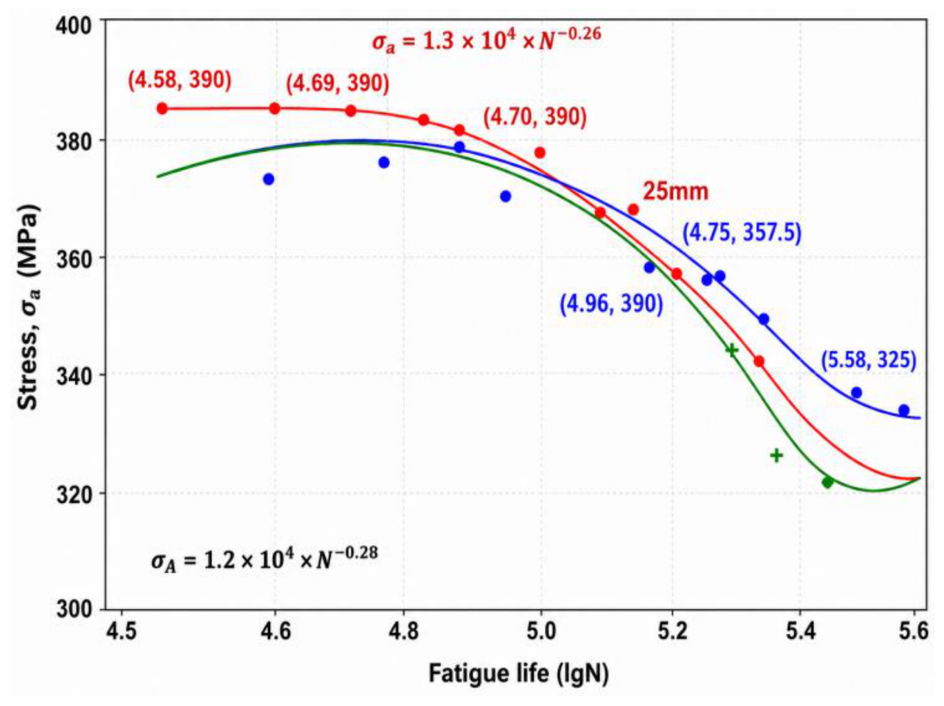
Table 5.
Raw Results of the Exploratory Axial Fatigue Tests at Different Stress Amplitudes.
| Source Diameter | Stress Amplitude (MPa) | Condition | Cycles, N |
|---|---|---|---|
| 19 mm | 390 | Fractured | 75,234 |
| 19 mm | 357.5 | Fractured | 48,986 |
| 19 mm | 325 | Run-out | 327,811 |
| 22 mm | 390 | Fractured | 82,378 |
| 22 mm | 357.5 | Fractured | 50,122 |
| 22 mm | 325 | Run-out | 351,492 |
| 25 mm | 390 | Fractured | 91,023 |
| 25 mm | 357.5 | Fractured | 55,846 |
| 25 mm | 325 | Run-out | 384,673 |
The quasi-static axial-stress results for well X9-D2-149 are summarized in Table 6 and Figure 9. At the wellhead, the 22 mm rod had a mean stress of 102.7 MPa and an alternating stress amplitude of 63.4 MPa. The actual fracture occurred in the 82nd rod at a depth of 681.04 m, where the corresponding values were only 29.8 and 18.6 MPa. At the bottom of the 22 mm section, the mean and alternating stresses were 31.7 and 19.6 MPa, respectively. At the top of the 19 mm section, the smaller cross-sectional area increased these values to 111.6 and 68.9 MPa, respectively. Thus, the actual fracture location did not coincide with the maximum nominal mean or alternating stress. The field stresses were also much lower than the stress amplitudes used in the exploratory laboratory tests. These observations reinforce that nominal axial stress alone does not capture the effects of corrosion pits, scratches, and other local discontinuities on fatigue resistance. Engineering assessment should therefore consider surface damage and associated local stress concentration in addition to nominal rod-string stresses.
3.8. Sucker-Rod Fracture Mechanism
The combined produced-fluid, metallographic, SEM/EDS, bulk-composition, tensile, fatigue, and field-loading results revealed three main features of this batch of failed sucker rods. First, the 16 wells had similar produced-fluid ionic backgrounds, and the fracture surfaces commonly contained corrosion pits, corrosion products, and secondary cracks, together with local O enrichment and varying levels of Cl and S. Second, no common abnormality in bulk microstructure or chemical composition could explain all failures, although localized discontinuities such as decarburization layers, inclusions, and scratches were observed in some rods. Third, residual tensile strength and cyclic response varied substantially among rods with different service histories, and the actual fracture location did not coincide with the position of maximum nominal axial stress. The failures therefore cannot be explained by any single environmental parameter, material abnormality, or nominal-load factor.
Corrosion pits provide an important link between environmental exposure and local cracking. The produced-fluid composition and the local O, Cl, and S detected on fracture surfaces are consistent with an environment capable of supporting pit formation. The co-occurrence of corrosion pits and secondary cracks further indicates a close association between surface damage and crack development. Decarburization layers, inclusions, and scratches represent additional local discontinuities. However, because the crack origins were not spatially matched one-to-one with specific defects, the available evidence does not establish that any individual crack initiated from a particular discontinuity.
The exploratory fatigue tests showed that service-exposed material can fracture under cyclic loading and that the measured fatigue life is highly scattered. Field calculations further showed that the actual fracture location did not correspond to the region of maximum nominal alternating stress. For downhole sucker rods containing corrosion pits and other local discontinuities, nominal axial stress alone is therefore insufficient to describe the conditions governing crack evolution. Local material condition, pre-existing surface damage, and cyclic loading should be evaluated together.
Based on the combined evidence, a representative six-stage damage-evolution process is proposed for this batch of failed sucker rods. First, localized corrosion develops on the rod surface and produces corrosion pits. Second, corrosion pits and local discontinuities, such as decarburization layers, inclusions, or scratches, form crack-susceptible regions. Third, microcracks initiate under cyclic loading. Fourth, the cracks propagate and may be accompanied by secondary cracking. Fifth, multiple cracks grow and coalesce, progressively reducing the effective load-bearing cross-section. Finally, rapid fracture occurs when the remaining cross-section can no longer sustain the applied load. The proposed sequence is therefore: “localized corrosion and pit formation–development of local crack-susceptible regions–microcrack initiation–cyclic-load-driven crack propagation–multiple-crack coalescence and reduction of effective load-bearing area–rapid fracture of the remaining cross-section” (Figure 10).
The proposed sequence is consistent with the corrosion pits, secondary cracks, environment-related elemental enrichment, residual-strength differences, and lamellar or step-like fracture morphologies observed in representative samples. Some rods also exhibited scratches, plastic deformation, or distinct loading histories, indicating substantial sample-to-sample variability. The proposed mechanism should therefore be regarded as a representative pathway for this dataset rather than as an identical fracture sequence for every rod. Overall, the evidence supports corrosion-fatigue damage involving both corrosive exposure and cyclic loading as a characteristic failure mode, with local material condition and pre-existing surface damage influencing crack initiation and subsequent growth.
4. Conclusions
(1) Well-by-well measurements from the 16 rod-failure wells showed average HCO₃⁻, Cl⁻, and SO₄²⁻ concentrations of 345.7, 0.129, and 2.55 mg/L, respectively, indicating an HCO₃⁻-dominated ionic environment. Representative fracture surfaces exhibited corrosion pits, corrosion products, secondary cracks, and lamellar or step-like morphologies. Selected fracture-surface microregions were enriched in O and contained detectable Cl and S, indicating environmental involvement in the damaged regions. Metallographic examination showed microstructures typical of quenched-and-tempered steel, together with localized discontinuities such as surface decarburization and nonmetallic inclusions.
(2) Residual tensile strength varied markedly among sucker rods with different origins and service histories. Neither service duration nor original rod diameter alone was sufficient to assess the remaining material condition of an in-service rod. The exploratory fatigue data also showed considerable scatter and were insufficient to establish a standard S–N relationship or determine a fatigue limit. The unfractured specimens at 325 MPa should therefore be interpreted only as run-outs within the prescribed test duration.
(3) Integration of the produced-fluid, fractographic, local-composition, metallographic, residual-mechanical-property, and cyclic-response evidence supports the following representative damage-evolution sequence: “localized corrosion and pit formation–development of local crack-susceptible regions–microcrack initiation–cyclic-load-driven crack propagation–multiple-crack coalescence and reduction of effective load-bearing area–rapid fracture of the remaining cross-section.” Corrosion pits provide a key surface link between wellbore environmental damage and cyclic crack initiation, while local material condition and cyclic loading jointly influence subsequent crack evolution.
Author Contributions
Conceptualization, Guangsheng Cao; Methodology, Guangsheng Cao and Jinbo Xiao; Investigation, Jinbo Xiao, Weibo Liu, Yu Wang, Yue Dan, Ning Zhang and YueJie Bai; Validation, Guangsheng Cao and Jinbo Xiao; Formal analysis, Jinbo Xiao; Writing—original draft, Jinbo Xiao; Writing-review & editing, Guangsheng Cao and Yue Dan; Supervision, Guangsheng Cao and Yue Dan; Project administration, Guangsheng Cao. All authors have read and agreed to the submitted version of the manuscript.
Funding
This work is financially supported by the National Natural Science Foundation of China (No. 51574089).
Data Availability Statement
The data presented in this study are available on request from the corresponding author.
Conflicts of Interest
The authors declare no conflict of interest.
References
- Zhang, F.; Jing, C.; Li, J.; Wang, B.; Ma, M.; Yi, T.; Hu, H. Low-Frequency Corrosion Fatigue Test Study of Sucker Rods under High-Salinity Well Fluids in Deep CBM Wells. Processes 2024, 12, 60. [Google Scholar] [CrossRef]
- Zhang, F.; Li, J.; Zhu, H.; Jing, C.; Wang, B.; Qi, Y. Study on Variable Stress Corrosion Susceptibility of Four Typical High-Strength Sucker Rods in High-Salinity Well Fluids. Processes 2023, 11, 2762. [Google Scholar] [CrossRef]
- Ding, H.; Zhang, A.B.; Qi, D.T.; Li, H.B.; Ge, P.L.; Qi, G.Q.; Ding, N.; Bai, Z.Q.; Fan, L. Failure Analysis of a Sucker Rod Fracture in an Oilfield. Eng. Fail. Anal. 2020, 109, 104300. [Google Scholar] [CrossRef]
- Li, H.; Wang, S.; Shao, L.; Jing, L.; Liu, Y.; Song, Q.; Wang, C.; Xue, B. Study on the Fracture Failure Mechanism of 00Cr12 Sucker Rods Under Service Conditions. J. Fail. Anal. Prev. 2025, 25, 3043–3054. [Google Scholar] [CrossRef]
- Cai, W.; Luo, S.; Li, W.; Wu, W.; Jia, K. An Advanced Fatigue Life Predicting Model for High-Strength Steel Sucker Rods Integrating Material Strength Parameters. Coatings 2025, 15, 1051. [Google Scholar] [CrossRef]
- Jiang, J.X.; Wan, X.L.; Li, K.J.; Du, J.G.; Liu, Y.H.; Jing, J.J.; Li, J.S. Research Progress of Sucker Rod Fracture Detection and Prediction Model. Eng. Fail. Anal. 2024, 159, 108119. [Google Scholar] [CrossRef]
- Fakher, S.; Khlaifat, A.; Hossain, M.E.; Nameer, H. A Comprehensive Review of Sucker Rod Pumps' Components, Diagnostics, Mathematical Models, and Common Failures and Mitigations. J. Pet. Explor. Prod. Technol. 2021, 11, 3815–3839. [Google Scholar] [CrossRef]
- Cai, W.; Li, W.; Xu, J. Study on the P-S-N Curve of Sucker Rod Based on Three-Parameter Weibull Distribution. Materials 2022, 15, 560. [Google Scholar] [CrossRef] [PubMed]
- Wu, Y.; Liu, S.; Ma, W.; Ran, X.; Qu, B. Machine Learning Method for Predicting the Fatigue Life of Sucker Rods. Eng. Fract. Mech. 2023, 282, 109161. [Google Scholar] [CrossRef]
- Tong, Z.; Zhou, G.; Zheng, W.; Zhang, H.; Zhou, H. Effects of Heat Treatment on the Microstructure and Mechanical Properties of a Novel H-Grade Sucker Rod Steel. Metals 2022, 12, 294. [Google Scholar] [CrossRef]
- Zhao, M.F.; Meng, X.J.; Long, Y.; et al. Fracture Analysis of a Grade HL Steel Sucker Rod Used in an Oilfield. J. Fail. Anal. Prev. 2022, 22, 377–384. [Google Scholar] [CrossRef]
- Han, Z.; Huang, X. Investigations on Corrosion Behaviors of Super-Strength Sucker Rod FG20 Steel in High SO4(2-) Environment. J. Mater. Res. Technol. 2019, 8, 788–794. [Google Scholar] [CrossRef]
- Yu, Y.; Yin, Z.; Huang, X. Experimental Study of Corrosion Behavior between the Material-Type and Process-Type Super-High Sucker Rod Steels in a Near Neutral High Sulfide Environment. J. Mater. Res. Technol. 2022, 17, 2593–2600. [Google Scholar] [CrossRef]
- Kret, N.V.; Svirska, L.M.; Venhrynyuk, T.P. Corrosion-Fatigue Crack Propagation in Exploited Pump Rods Made of 20N2M Steel. Mater. Sci. 2020, 56, 279–283. [Google Scholar] [CrossRef]
- Kopei, B.V.; Zvirko, O.I.; Venhrynyuk, T.P.; Slobodyan, Z.V.; Shtoiko, I.P. Elevation of the Fatigue Strength of Pump Rods as a Result of Treatment with a Special Medium. Mater. Sci. 2020, 56, 125–131. [Google Scholar] [CrossRef]
- Vynnykov, Y.; Kharchenko, M.; Manhura, S.; Muhlis, H.; Aniskin, A.; Manhura, A. Analysis of Corrosion Fatigue Steel Strength of Pump Rods for Oil Wells. Min. Miner. Depos. 2022, 16, 31–37. [Google Scholar] [CrossRef]
- Krechkovska, H.V.; Kopei, B.V.; Bakun, B.M.; Kopei, I.B. Peculiarities of Fatigue Cracks Growth in Steel and Composite Sucker Rods. Procedia Struct. Integr. 2022, 42, 1406–1413. [Google Scholar] [CrossRef]
- Kopei, B.V.; Krechkovska, H.V.; Nisonskyi, V.P.; Bakun, B.M. Regularities of Growth of Fatigue Cracks in Hybrid Pumping Rods. Mater. Sci. 2022, 57, 549–556. [Google Scholar] [CrossRef]
- Kopei, B.V.; Krechkovska, H.V.; Kopei, I.B.; Bakun, B.M. Specific Features of Corrosion-Fatigue Fracture of Steel and Hybrid Pump Rods. Mater. Sci. 2023, 58, 768–773. [Google Scholar] [CrossRef]
- Kopei, B.V.; Stefanyshyn, A.B.; Venhrynyuk, T.P. Fatigue Strength of Hybrid Pump Rods. Mater. Sci. 2019, 54, 739–742. [Google Scholar] [CrossRef]
- Fatoba, O.; Akid, R. On the Behaviour of Small Fatigue Cracks Emanating from Corrosion Pits: Part I-The Influence of Mechanical Factors. Theor. Appl. Fract. Mech. 2022, 117, 103154. [Google Scholar] [CrossRef]
- Fatoba, O.; Akid, R. The Influence of Corrosion Pit-Pit Spacing on the Pit-to-Crack Transition and Fatigue Lifetime. Fatigue Fract. Eng. Mater. Struct. 2022, 45, 2676–2692. [Google Scholar] [CrossRef]
- Yu, Y.; Huang, X.; Wang, Y.; Yang, Z. Experiment and Simulation of High-Cycle Corrosion Fatigue Damage Evolution and Corrosion Pit Tolerance Analysis of Crack Nucleation. Fatigue Fract. Eng. Mater. Struct. 2022, 45, 1435–1447. [Google Scholar] [CrossRef]
- Katona, R.M.; Karasz, E.K.; Schaller, R.F. A Review of the Governing Factors in Pit-to-Crack Transitions of Metallic Structures. Corrosion 2023, 79, 72–96. [Google Scholar] [CrossRef] [PubMed]
- Jie, Z.; Zhang, Z.; Susmel, L.; Zhang, L.; Lu, W. Corrosion Fatigue Mechanisms and Evaluation Methods of High-Strength Steel Wires: A State-of-the-Art Review. Fatigue Fract. Eng. Mater. Struct. 2024, 47, 2287–2318. [Google Scholar] [CrossRef]
- Farhad, F.; Smyth-Boyle, D.; Zhang, X. Fatigue of X65 Steel in the Sour Corrosive Environment-A Novel Experimentation and Analysis Method for Predicting Fatigue Crack Initiation Life from Corrosion Pits. Fatigue Fract. Eng. Mater. Struct. 2021, 44, 1195–1208. [Google Scholar] [CrossRef]
- Balbin, J.A.; Chaves, V.; Larrosa, N.O. Pit to Crack Transition and Corrosion Fatigue Lifetime Reduction Estimations by Means of a Short Crack Microstructural Model. Corros. Sci. 2021, 180, 109171. [Google Scholar] [CrossRef]
- Sadananda, K.; Vasudevan, A.K. Analysis of Pit to Crack Transition under Corrosion Fatigue and the Safe-Life Approach Using the Modified Kitagawa-Takahashi Diagram. Int. J. Fatigue 2020, 134, 105471. [Google Scholar] [CrossRef]
- Cui, C.; Chen, A.; Ma, R. An Improved Continuum Damage Mechanics Model for Evaluating Corrosion-Fatigue Life of High-Strength Steel Wires in the Real Service Environment. Int. J. Fatigue 2020, 135, 105540. [Google Scholar] [CrossRef]
- Qvale, P.; Zarandi, E.P.; As, S.K.; Skallerud, B.H. Digital Image Correlation for Continuous Mapping of Fatigue Crack Initiation Sites on Corroded Surface from Offshore Mooring Chain. Int. J. Fatigue 2021, 151, 106350. [Google Scholar] [CrossRef]
- Li, R.; Miao, C.; Zhuang, M. Experimental and Numerical Investigation of Stress Concentration Factor of Cable Steel Wire with Corrosion Pits. KSCE J. Civ. Eng. 2020, 24, 1581–1592. [Google Scholar] [CrossRef]
- Wan, S.; Zhou, H.; Li, L.; Wang, C.; De Filippo, M.; Gong, F. Degradation of Artificially Corroded Galvanized High-Strength Steel Wires: Corrosion Morphology and Mechanical Behavior. Constr. Build. Mater. 2022, 346, 128387. [Google Scholar] [CrossRef]
- Liu, X.; Yan, B.; Sun, H. Fatigue Life Prediction of High Strength Steel with Pitting Corrosion under Three-Point Bending Load. Metals 2023, 13, 1839. [Google Scholar] [CrossRef]
- Malikova, L.; Miarka, P. Fatigue Crack Propagation near a Corrosion Pit in a HSS Specimen. Theor. Appl. Fract. Mech. 2024, 129, 104214. [Google Scholar] [CrossRef]
- Tang, S.; Xu, H.; Ao, N.; et al. Experimental Investigation on Corrosion Fatigue Crack Initiation and Growth of Heat-Treated U75V Rail Steel. Int. J. Fatigue 2024, 178, 107973. [Google Scholar] [CrossRef]
- Zhu, J.; Jie, Z.; Chen, C.; Zheng, H.; Wang, W. Fatigue Crack Propagation of Corroded High-Strength Steel Wires Using the XFEM and the EIFS. Materials 2023, 16, 4738. [Google Scholar] [CrossRef] [PubMed]
- Lu, C.; Yao, Q.; Li, N.; et al. Corrosion Fatigue Cracking Behaviors of Q690qE High-Strength Bridge Steel as a Weld Joint in Simulated Marine Environment. Fatigue Fract. Eng. Mater. Struct. 2024, 47, 4341–4355. [Google Scholar] [CrossRef]
- Cai, J.; Sun, L.; Ma, H.; Li, X. Corrosion Characteristics of Q690qE High-Strength Bridge Steel in Simulated Coastal-Industrial Environment and Its Influence on Mechanical and Corrosion Fatigue Behaviors. Constr. Build. Mater. 2022, 341, 127830. [Google Scholar] [CrossRef]
- Yue, Y.; Gao, S.; Li, N.; Zhang, R. High-Cycle Fatigue Performance of Corroded Q690E High Strength Steel and Q690qENH High-Strength Weathering Steel. Constr. Build. Mater. 2023, 401, 132835. [Google Scholar] [CrossRef]
- Guo, H.; Wei, H.; Li, G.; Wang, Y. Experimental Research on Fatigue Performance of Corroded Q690 High-Strength Steel. J. Mater. Civ. Eng. 2021, 33, 04021304. [Google Scholar] [CrossRef]
- Wang, J.; Sun, L.; Ma, H.; et al. Comparative Study on Mechanical and Corrosion Fatigue Properties of High-Strength Bridge Steels Produced by TMCP and Intercritical Quenching & Tempering Process. Mater. Sci. Eng. A 2022, 853, 143771. [Google Scholar] [CrossRef]
- Liu, H.; Zan, C.; Zong, L. Corrosion Fatigue Behaviour of Q690D High-Strength Steel Considering the Effect of Coupling. Int. J. Fatigue 2024, 183, 108243. [Google Scholar] [CrossRef]
- Liu, H.; Zong, L.; Xu, K.; Yang, L. Experimental Investigation on Fatigue Performance of Corroded Q690D High-Strength Steel. J. Constr. Steel Res. 2025, 227, 109405. [Google Scholar] [CrossRef]
- Li, W.; Jing, J.; Sun, J.; et al. Investigation of the Corrosion Characteristics and Corrosion Inhibitor Action on J55 Steel in Produced Water. Sustainability 2023, 15, 3355. [Google Scholar] [CrossRef]
- Udowo, V.M.; Yan, M.; Liu, F.; Ikeuba, A.I. Role of Fe Oxide in the Underdeposit Corrosion of Pipeline Steel in Oilfield Produced Water Containing SRB. Mater. Corros. 2024, 75, 118–129. [Google Scholar] [CrossRef]
- Shi, P.; Du, M.; Wang, J. Effect of Alcaligenes sp. on Corrosion Behavior of X65 Steel in Simulated Offshore Oilfield-Produced Water. Front. Microbiol. 2023, 14, 1127858. [Google Scholar] [CrossRef] [PubMed]
- Gao, M.; Wang, H.; Han, E.H. Effect of Chloride and Bicarbonate Ions on Corrosion Behavior of Carbon Steel in Anaerobic Environment. Mater. Today Commun. 2023, 36, 106873. [Google Scholar] [CrossRef]
- Wasim, M.; Djukic, M.B. External Corrosion of Oil and Gas Pipelines: A Review of Failure Mechanisms and Predictive Preventions. J. Nat. Gas Sci. Eng. 2022, 100, 104467. [Google Scholar] [CrossRef]
- Shojai, S.; Schaumann, P.; Bromer, T. Probabilistic Modelling of Pitting Corrosion and Its Impact on Stress Concentrations in Steel Structures in the Offshore Wind Energy. Mar. Struct. 2022, 84, 103232. [Google Scholar] [CrossRef]
- Yan, K.; Liu, G.; Li, Q.; Jiang, C.; Ren, T.; Li, Z.; Xie, L.; Wang, L. Corrosion Characteristics and Evaluation of Galvanized High-Strength Steel Wire for Bridge Cables Based on 3D Laser Scanning and Image Recognition. Constr. Build. Mater. 2024, 422, 135845. [Google Scholar] [CrossRef]
Figure 3.
Fracture-Surface Samples and Source Distribution of the 16 Failed Sucker Rods.
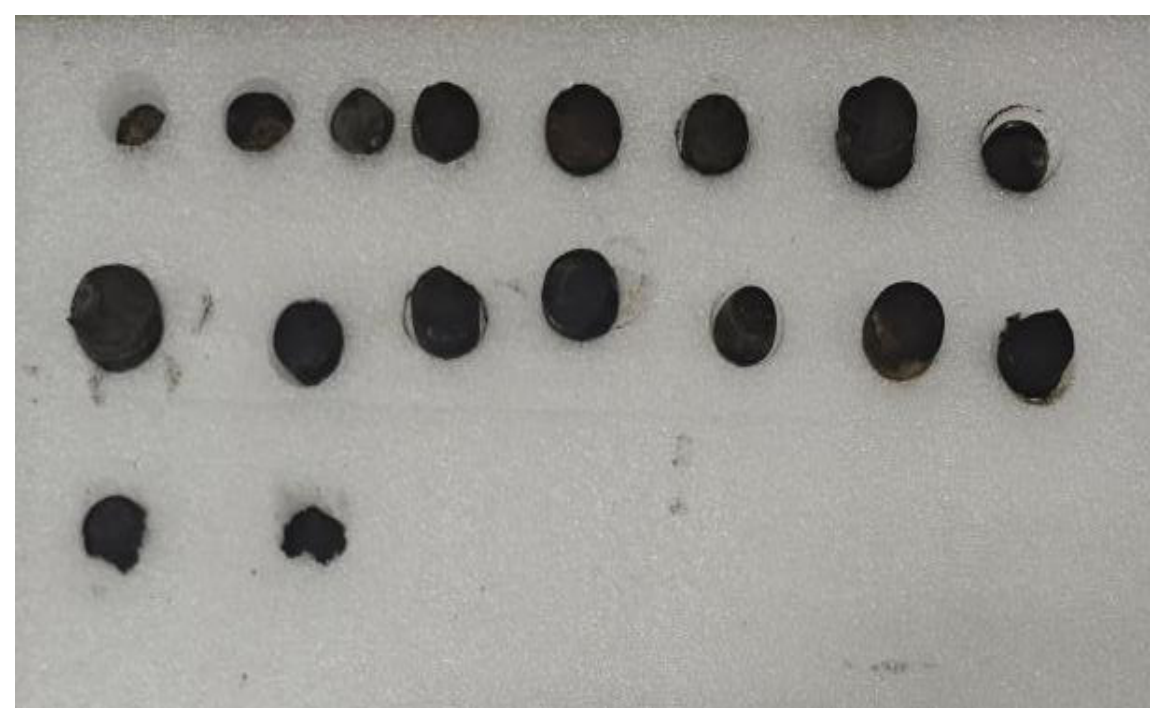
Figure 4.
Representative Metallographic Microstructures of Sucker Rods with Different Diameters: (a) XF8-1-518 (19 mm); (b) X8-D3-320 (22 mm); (c) X8-2-E222 (25 mm).
Figure 4.
Representative Metallographic Microstructures of Sucker Rods with Different Diameters: (a) XF8-1-518 (19 mm); (b) X8-D3-320 (22 mm); (c) X8-2-E222 (25 mm).
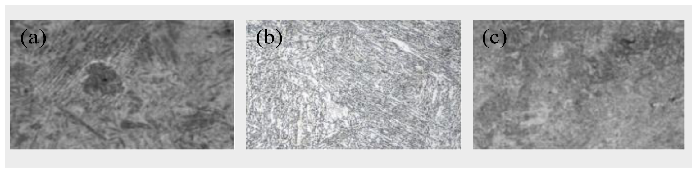
Figure 6.
Distribution of Major Anion Concentrations in Produced Fluids from the 16 Wells with Sucker-Rod Failures.
Figure 6.
Distribution of Major Anion Concentrations in Produced Fluids from the 16 Wells with Sucker-Rod Failures.
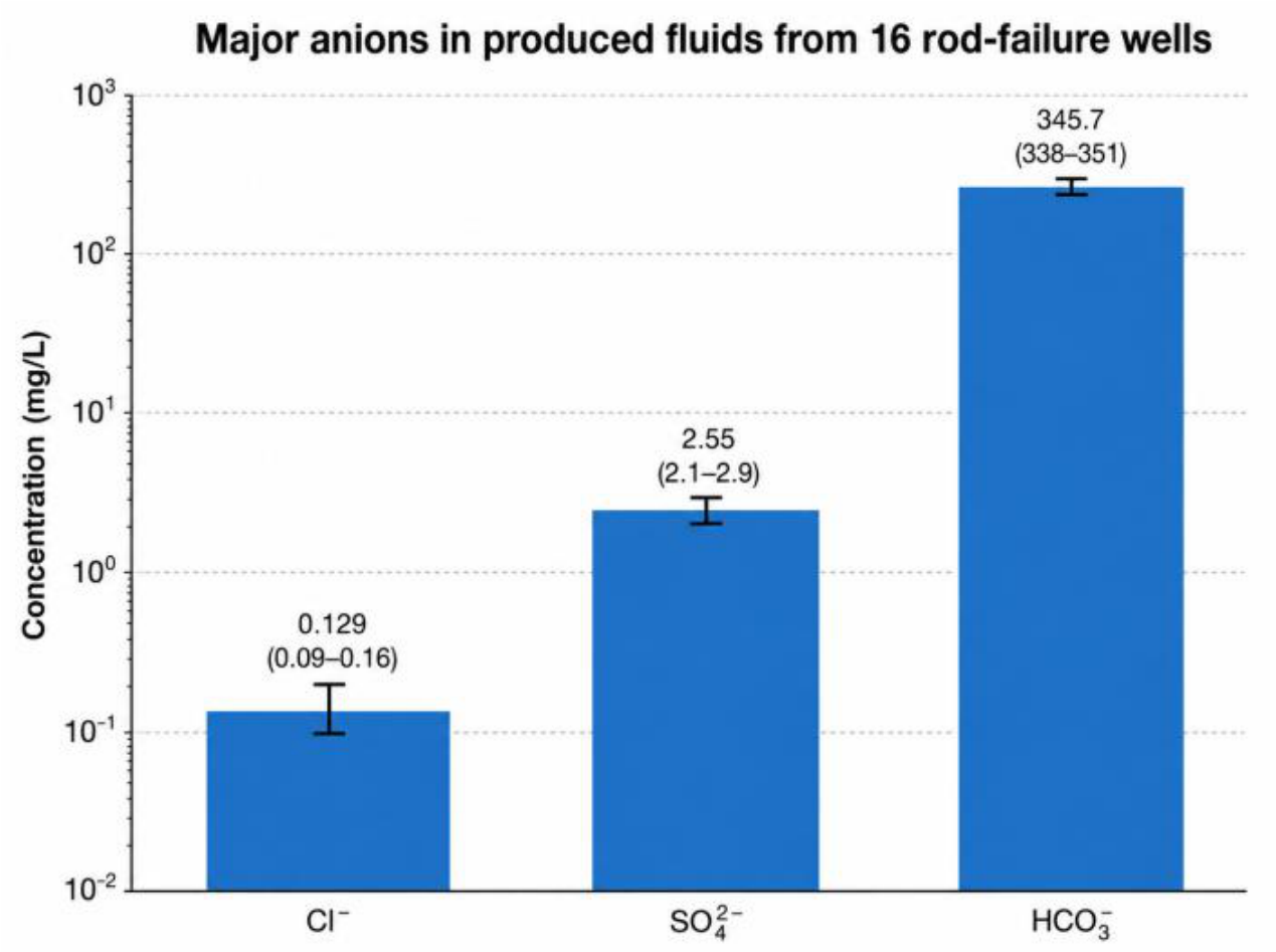
Figure 9.
Nominal Mean and Alternating Stresses at Representative Sucker-Rod-String Locations in Well X9-D2-149.
Figure 9.
Nominal Mean and Alternating Stresses at Representative Sucker-Rod-String Locations in Well X9-D2-149.
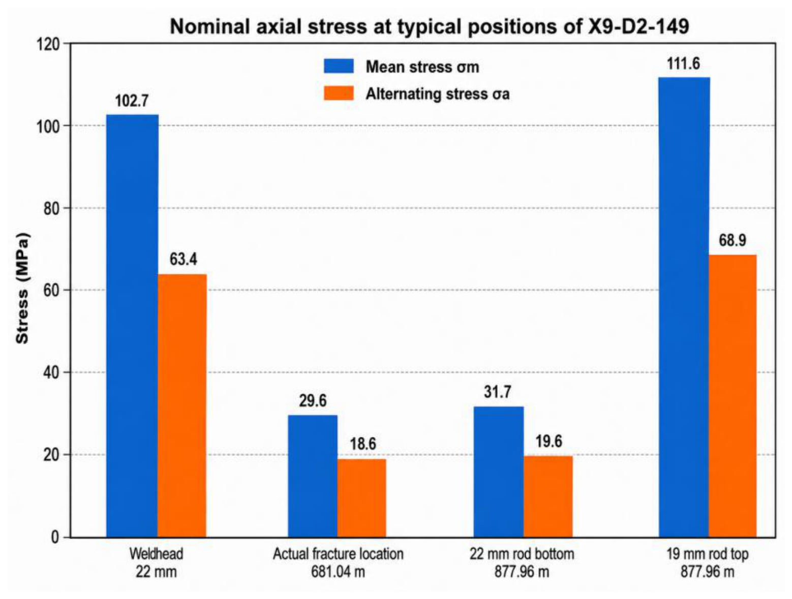
Figure 10.
Six-Stage Evolution of Sucker-Rod Crack Initiation and Propagation under Coupled Corrosion–Fatigue Effects.
Figure 10.
Six-Stage Evolution of Sucker-Rod Crack Initiation and Propagation under Coupled Corrosion–Fatigue Effects.
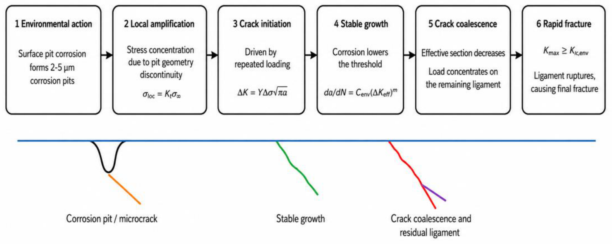
Table 3.
Major-Ion Concentrations in Produced Fluids from the 16 Wells with Sucker-Rod Failures.
| Ion | Mean (mg/L) | Range (mg/L) |
|---|---|---|
| HCO₃⁻ | 345.7 | 338–351 |
| Cl⁻ | 0.129 | 0.09–0.16 |
| SO₄²⁻ | 2.55 | 2.1–2.9 |
| CO₃²⁻/OH⁻ | 0 | Not detected |
| Fe³⁺ | <0.4 | Below detection limit |
Table 4.
Tensile Strength and Reported Strength-Degradation Rate of Representative Samples.
| Sample | Diameter / Condition | Service (years) | Alternating Load / Operating Condition | Tensile Strength (MPa) | Degradation (%) |
|---|---|---|---|---|---|
| X11-3-B326 | 19 mm used rod | 4.3 | 27.36 kN; insufficient fluid supply | 849.3 | 15.74 |
| X11-2-B221 | 19 mm used rod | 22.8 | Very long-term service | 930.6 | 20.80 |
| X9-D3-138 | 22 mm used rod | 2.8 | 70.28 kN; σa = 176.78 MPa | 989.0 | 24.32 |
| X9-D2-149 | 22 mm used rod | ≥5.6 | Mid-string fracture | 774.9 | 17.67 |
| X13-D1-219 | 22 mm refurbished rod | 5.6 | Residual damage after refurbishment to be verified | 1022.6 | 13.25 |
| X10-5-SB3622 | 25 mm used rod | 5.5 | High stroke rate/high load | 866.9 | 8.69 |
| X9-D2-140 | 25 mm used rod | 12.5 | Insufficient fluid supply, long-term corrosion | 930.6 | 21.33 |
| X8-2-B183 | 25 mm used rod | 17.9 | Long-term service | 1015.6 | 25.71 |
Table 6.
Nominal Axial Stresses at Representative Locations Along the Sucker-Rod String in Well X9-D2-149.
Table 6.
Nominal Axial Stresses at Representative Locations Along the Sucker-Rod String in Well X9-D2-149.
| Location | Depth (m) | Diameter (mm) | Max. Stress (MPa) | Min. Stress (MPa) | Mean Stress (MPa) | Alt. Stress (MPa) |
|---|---|---|---|---|---|---|
| Wellhead | 0 | 22 | 166.1 | 39.3 | 102.7 | 63.4 |
| Actual fracture (82nd rod) | 681.04 | 22 | 48.5 | 11.2 | 29.8 | 18.6 |
| Bottom of 22 mm rod section | 877.98 | 22 | 51.2 | 12.1 | 31.7 | 19.6 |
| Top of 19 mm rod section | 877.98 | 19 | 180.5 | 42.7 | 111.6 | 68.9 |
Disclaimer/Publisher’s Note: The statements, opinions and data contained in all publications are solely those of the individual author(s) and contributor(s) and not of MDPI and/or the editor(s). MDPI and/or the editor(s) disclaim responsibility for any injury to people or property resulting from any ideas, methods, instructions or products referred to in the content. |
© 2026 by the authors. Licensee MDPI, Basel, Switzerland. This article is an open access article distributed under the terms and conditions of the Creative Commons Attribution (CC BY) license (http://creativecommons.org/licenses/by/4.0/).
Copyright: This open access article is published under a Creative Commons CC BY 4.0 license, which permit the free download, distribution, and reuse, provided that the author and preprint are cited in any reuse.