

Submitted:
29 August 2026
Posted:
31 August 2026
You are already at the latest version
Abstract
Articulated steering systems are pivotal in off-road vehicles operating in constrained and narrow spaces. This research explores the mathematical modelling of the Stepper Motor Driven Orbitrol Valve (SMDOV), focusing on steady-state performance and validating findings through experimental data. Using the MATLAB®/Simulink platform, a comprehensive mathematical model of the system is developed. Experimentally, a sprocket-chain drive mechanism links the stepper motor to the orbitrol valve, which can provide a fixed steering rate. Further, the effects of valve leakage, flow responses under varying steering rates, and external loads are analysed. The model validation offers insights into the influence of damping coefficients and leakage resistance on the system performance. Moreover, an empirical relationship is proposed based on system inputs for future investigations into the dynamic behaviour of the Orbitrol valve-driven articulated steering system. This work highlights key parametric values of the SMDOV system and advances the automation of articulated vehicle steering mechanisms. This article provides more significant insights about the stepper motor driven orbitrol valve characteristics. It helps in developing the orbitrol valve controlled automatic steering mechanism for better control of the articulated vehicles.
Keywords:
heavy-duty vehicle
; hydraulic power steering
; parameter estimation
; steady state behaviour
; orbitrol valve
1. Introduction
Articulated off-road vehicles (AOV), commonly used in construction, agriculture, and mining, rely heavily on hydraulic power to manage high steering loads. The steering operations in AOV are carried out by the simultaneous extension and retraction of hydraulic steering cylinders. The flow directed to these cylinders can be regulated through various means, such as displacement control (DC) or steering valves like the proportional direction control valve (PDCV) or orbitrol valve. While significant research has focused on the kinematic and dynamic modeling of articulated steering systems (ASS) using DC or PDCV, studies examining the steady-state behaviour of the orbitrol valve in articulated steering systems are notably absent.
Existing articulated machinery possesses the hydraulically operated steering cylinders controlled either through manually operated orbitrol valve or controller commanded proportional directional control valve (PDCV) or Servo valve. The selection of control valves depends on various factors like responses, expenses, and the machinery’s working condition. The present investigation proposes the stepper motor-operated orbitrol valve in place of a manual operated orbitrol valve or PDCV for the quick response and automation of articulated steering system. The steady-state investigation of the stepper motor driven orbitrol valve and the dynamic response characterization of the off-road vehicles’ steering system are exciting research topics.
The research on the articulated steering system using the orbitrol valve is very limited; however, substantial research has been carried out on the displacement controlled (pump-controlled), and PDCV controlled (valve-controlled) articulated steering system. Studies on the steady-state characteristics of the hydraulic components like pump, motor, directional control valves (DCV), pressure control valves, and flow control valves provide a foundation for the detailed system modeling and the overall system dynamics investigation (e.g., steering system). In this regard, literary works on hydraulic components’ steady-state or dynamic characteristics and overall system performance investigation with varying parameters have been discussed below.
Ei et al. [1] used steady-state characteristics of the steering response and directional stability of the articulated vehicle to select appropriate vehicle configuration and design parameters to meet particular operational requirements. Watton [2] in his investigation, studied the steady-state characteristics of the hydraulic components and the steady-state performance investigation of the open-loop and closed-loop HST systems. He estimated the port leakage resistances, torque-loss coefficients, leakage volume, leakage resistance, and damping coefficients for different hydraulic components. The variation of flow with pressure and load has also been analyzed for servo valves, directional control valves with overlapped and under-lapped spools. Similar to this work, the researchers performed a steady-state investigation of hydro-motors and proportional pressure relief valves ([3,4,5]).
Meng et al. [6] worked on the dynamic analysis of a proportional solenoid valve-controlled steering system for automatic transmission applications. They investigated the response of winding current, inductance, flux linkage, mover displacement and velocity, and the electromagnetic force for DC and PWM signal through simulation and experiments. The spool dynamics of the proportional valve used for power steering purpose is improved by using Peak and Hold () technique proposed by Amirante et al. [7]. technique provides to change the frequency, duty cycle, and amplitude of the PWM signal. By modulating the PWM frequency signal, the spool position’s overshoot is reduced, and the valve opening time is also reduced.
Furthermore, Forental et al. [8] investigated the proportional valve characteristics based on experimental static flow characteristics and spool displacement transfer function on the input current. Bode plot for the hydraulic system is obtained, and results show that for frequencies up to 3 Hz, the proposed model provides satisfactory results. The above work only focused on the proportional valve characteristics whereas, Ferrari et al. [9] developed simulation model of PDCV with servo actuator in the LMS AMEsim platform and validated experimentally. Another work on proportional integrated control valve that operates in the open-center hydraulic steering systems was conducted by Bo et al. [10] and dynamic performances were established using the MATLAB/Simulink model, and the properties of steady flow, load flow, and pressure losses of the valve were analyzed. Static flow curves with different voltages and change in valve flow and differential pressure across the valve with a step-change in drive voltage have also been discussed. Based on the experimental results, the performance of the proposed valve is well referring to the tracing and quick response characteristics, which meet the requirements of tractor navigation and control.
To add the advantages of the electric power system, Hiremath et al. [11] simulate the spool dynamics of the Electro-Hydraulic Servo Valve (EHSV) using Simulink model for the steady-state operation of the valve. A simplified linearization analysis method for the EHSV in the frequency domain is obtained by Zhang et al. [12]. Characteristics curves of the bode plots and the key parameters affecting the system have been studied. The bandwidth of the proposed system is only 7.38 rad/s (1.17 Hz). This research is helpful for the design and optimization of a heavy vehicle dynamic steering system.
An alternative to the EHSV is developed by Milecki et al. [13] using a proportional valve coupled with Permanent Magnet Synchronous Motor (PMSM). The spool of the proportional valve is operated by the PMSM. The modeling of the spool dynamics has been simulated in MATLAB and validated experimentally. The results assure better properties than the EHSV operated valves. Vasile et al. [14] carried out research on the steady-state behavior of the open center flow control valves included in the hydraulic steering system of the vehicle. Determined the appropriate value of the valve coefficients, computed the pressure variations for different supply flow and valve opening mathematically, and validated those results experimentally.
To determine the relationship between the pressure, flow rate, and angular displacement of the rotary valves, Li et al. [15] proposed a rotary direct drive digital valve (RDDDV) coupled to a stepper motor. Based on the simulation and experimental results, it was inferred that the pressure, flow rate, and angular displacement of the rotary valve follows a nonlinear trend relationship. However, under a constant load pressure, the flow characteristics and the steady-state flow torque characteristics of the rotary valve with rectangular throttle orifices are observed a linear trend. The time constant of the orbitrol valve through variations in volume regulation is formulated by [16] .
The experimental results suggest that the accurate characterization of the nonlinear properties of the hydraulic steering components is essential. This can serve as an effective tool for seeking optimal articulated frame steering system design. Zardin et al. [17] performed a study on the construction and working of the orbitrol valve and studied variation flow curves concerning the rotary area. Further conducted experimental performance investigation and determining the influence of the design parameters of the hydraulic steering system used for tractors. Given the importance of steady-state analysis in determining component parameters for accurate simulation, this study delves into the SMDOV-controlled articulated steering system. while the authors already discussed and published work related to modeling analysis [18], dynamic analysis and closed-loop control for SMDOV systems [19], and comparison analysis with PDCV steering systems [20], respectively. The present study focuses solely on steady-state investigation. The uniqueness of the SMDOV approach for the automation of the steering system in underground mining vehicles underscores the novelty of this research. The steady-state analysis presented here serves as a foundational step toward developing a robust automated steering system for articulated vehicles.
2. System Description
Articulated vehicles are mostly off-road machinery like Front End Loader (FEL) and Load Haul Dump (LHD) machines used for operations in the constrained pathway with a sharp turning radius. These machines have two rigid body sections connected with articulated joint and steered through symmetrically placed hydraulic cylinder(s), called steering cylinder(s). The steering cylinders are placed between the two rigid bodies of the vehicle symmetrically and one on each side of the articulated joint. The mechanical arrangement of the steering cylinders’ is such that the push and pull force on the steering cylinders about the articulated joint causes the steering effect, where the steering cylinders are actuated through a hydraulic power source.
To investigate the performances of the ASS, a test rig is designed with one steering cylinder, where the speed of the steering cylinder, during its extension or retraction, is controlled by the orbitrol valve. The steering load is adjusted by the viscous-inertial loading arrangements. The corresponding hydraulic circuit of the steering system is shown in Figure 1 and The pictorial view of the fabricated test platform is shown in Figure 2.
2.1. Functioning of the Test-Rig
Figure 1 shows the hydraulic circuit of a simplified articulated steering system arrangement consisting of a fixed displacement main pump with an almost constant volume flow rate of which drives the steering cylinder during left or right turning. The steer’s rate, i.e., extension/retraction velocity of the steering cylinder is controlled through the orbitrol valve operations. In contrast, the steering cylinder’s load is varied by the help of the dead weight trolley for inertial load and the loading cylinder for the resistive load. When there is no steering input, The hydraulic flow fed from the main pump to the hydraulic valve is diverted to the tank. With the steering input to the hydro motor, the change in position of the proportional DCV is achieved with the help of a lever. The change in position of the proportional DCV causes the connection of P and T ports to the service ports of the steering cylinder. The inertial load on the steering cylinder is varied by increasing or decreasing the number of the deadweight block on the frictionless trolley, whereas the resistive/ viscous loading is adjusted by changing the set pressure of the or during retraction or extension of load cylinder, respectively.
The loading pump is acting as a boost pump to the low-pressure chamber of the loading cylinder. The PRVs in the main pump and the loading pump is used as a safety valve to prevent the system from over-pressurization. The pressure transducers (, , , , and ), flow sensors ( and ), and the load sensor are used to record the operating parameters for detailed analysis. The specification details about the sensors used is listed in Table . The functioning of the orbitrol steering valve is mentioned in the next sub-section.
2.2. Functioning of the Orbitrol Steering Valve
Referring to Figure 1, the function of the steering valve unit is schemed in Figure 3, where the operation of the valve is shown for straight, i.e., neutral and right turn of the drive. In the neutral condition, as there is no relative motion between the spool and sleeve, no fluid flow occurs to the metering section. The total flow from the main pump () is diverted to the tank () to avoid power loss.
During the right turn, i.e., clockwise rotation of the steering column causes relative motion between the spool and sleeve and rotates the metering unit’s rotor through the cardan shaft. The main flow from the pump enters the sleeve through the specific holes designated on the sleeve surface. Due to the relative motion between the spool and sleeve, grooves on the spool provide a path to enter into the metering section () and the tank (). Depending on the steering wheel rotation speed, the part of the main flow is supplied to the steering cylinder/s (), and the rest of the flow is diverted to the tank. As the rotor rotates, the suction and discharge take place at the metering unit continuously as long as the steering wheel is kept on rotating. The return flow from the steering cylinders is connected to the tank through holes provided on the sleeve (i.e., = + ). Similarly, during the left turn, i.e., counter clockwise rotation of the steering column, the delivered flow from the metering unit is fed to another service port B of the steering cylinder.
3. Mathematical Modelling of the Proposed System
To develop the simulation model of the hydraulic system mentioned in Figure 2, the mathematical model of the major components like orbitrol valve, steering cylinder with resistive viscous and inertial load, etc., are described in the subsequent sub-section. Using the mathematical model of the components, the simulation model of the hydraulic system for the ASS is developed on a Matlab-Simulink environment.
3.1. Mathematical Modelling of the Major Components
The flow supplied by the pump enters into the spool-sleeve section of the orbitrol valve where volume flow to the metering unit and by-pass flow to the tank is regulated by the rotation angle of the steering column. The flow distribution in the spool-sleeve assembly of the orbitrol valve shown in Figure 4 is expressed by,
where, the first term is the main supply from the pump; the second term represents the flow entering the metering unit is dependent on the angular speed of the steering column; the third term indicates the fluid flow rate compressed in the hose connecting the main pump and the orbitrol valve; and the last term indicates the flow diverted to the tank dependent on the angular opening between the supply and the tank lines controlled by the angular position of the steering column. The flow equation for the metering unit of the orbitrol valve (Section 3.1) is expressed by
Where, is the displacement of the orbitrol valve and is the speed at which the steering column is rotating The equation for the flow diverted to the tank is given by
The equation for the flow coming out of the orbitrol valve is expressed by
where, the first term represents the net fluid flow rate entering into the cylinder to port A or B during extension or retraction, respectively; the second term represents the ideal fluid flow entering into the metering unit ; the third term represents the compressible flow loss inside the steering valve unit; and the last term indicates the leakage losses in the steering valve . Fluid flow rate entering into the steering cylinder (high-pressure chamber) during its extension is expressed by
where, the second term represents the extension velocity of the steering cylinder; the third term represents the compressible flow loss in the cylinder plenum (higher pressure side); and the last term indicates the internal cylinder leakage. Fluid flow rate coming out of the steering cylinder (low-pressure chamber) during extension
where, the second term represents the extension velocity of the steering cylinder with respect to the rod end side variable; the third term represents the compressible volume flow rate in cylinder plenum (low-pressure side during extension); and the last term indicates the leakage flow rate added to the low-pressure side chamber. The effective force generated during extension of the steering cylinder is expressed by
where, the first term on the right-hand side represents the resistive damping force; the second term indicates the resistive frictional force; the third term defines the inertial load; and the last term indicates the resistive viscous load on the steering cylinder during extension. The resistive viscous load is applied through the loading cylinder arrangement, as shown in Figure 3.
Fluid flow rate entering into the steering cylinder (high-pressure chamber) during its retraction is expressed by
Where, the second term represents the retraction velocity of the steering cylinder; the third term represents the compressible flow loss in the cylinder plenum (higher pressure side); and the last term indicates the cylinder internal leakage. Fluid flow rate coming out of the steering cylinder (low-pressure chamber) during retraction
where, the second term represents the retraction velocity of the steering cylinder with respect to the piston end side variable; the third term represents the compressible volume flow rate in cylinder plenum (low-pressure side during retraction); and the last term indicates the leakage flow rate added to the low-pressure side chamber. The effective force generated during retraction of the steering cylinder is expressed by
where, the first term on the right-hand side represents the resistive damping force; the second term indicates the resistive frictional force; the third term defines the inertial load; and the last term indicates the resistive viscous load on the steering cylinder during retraction. The resistive viscous load is applied through the loading cylinder arrangement, as shown in Figure 3. The resistive force generated by loading cylinder during extension/retraction of steering cylinder Figure 3 is expressed by
Equations 1 through 12 are used to develop the simulation model of the hydraulic system, where the loss co-efficient and other parametric values like , , etc. are estimated through experiments and the operating parameters like pressures, flow, and cylinder velocity/positions are obtained through suitable sensors fitted as mentioned in Figure 2 and Figure 3.
3.2. Development of Simulation Model
The assumption made in the development of the simulation model are:
- A constant volume flow rate is supplied to the orbitrol steering valve unit. However, in actual practice, there will be a slight reduction in flow rate due to volumetric losses of the pump. The effect of pump leakage is neglected due to the fact that the orbitrol valve is operating at maximum flow demand lesser than the flow supplied by the pump.
- The effect of hydraulic hose properties is not considered in the simulation model.
Based on the system’s operational features and the orbitrol valve, the simulation model of the hydraulic system is developed in MATLAB/Simulink platform considering the assumptions mentioned above, which is shown in Figure 4. The parametric values of the components are estimated through experiments, and they are shown using from/goto command through pink colour in the simulation model. Table shows the details of the hydraulic components alon with their specifications used and the fluid property parametric values used for simulation is mentioned in Table .
4. Experimental Analysis and Verification of the Model
4.1. Experimental Procedure
To investigate the orbitrol steering valve’s characteristics and the steering system, the hydraulic system is operated repeatedly to nullify the sensors’ repeatability and hysteresis errors and the hydraulic system. Also, the variation of viscosity and the bulk modulus are assumed to be constant and independent of the operating temperature of the mineral oil (grade Servo System 68). This is mainly because the variation of the operating temperature of the said oil is kept approx. around 50±20C, which is achieved by controlling the operating hour of the intermittently desired steering system.
During the operation of the articulated steering system Figure 2, a constant fluid rate of flows to the orbitrol vale. Depending on the angular rotation of the steering column of the orbitrol valve, the pump flow is regulated to the steering cylinder, and the rest flow is by-passed to the tank to avoid losses. The angular rotation of the steering column is performed through both manual mode and stepper mode individually for identifying and minimizing the response errors if any. The leakage resistance of the metering unit of the orbitrol valve and the hydraulic cylinder, the damping coefficient and friction force of the cylinder, and the displacement of the orbitrol valve is estimated experimentally using equations 1 through 12.
The operating parameters in considered in equations like flow, pressure, and cylinder position-force are recorded from sensors while supplying the steady-state command to the stepper motor (PWM frequency) and the set pressure of the PRVs in the loading unit. The steady-state investigation is carried out for the different magnitude of steering force varied from 15kN to 35kN with an interval of 5kN and input PWM frequency signal ranging from 250Hz to 400Hz with an interval of 50Hz. Also, a constant block mass of 20kg is considered during the experiment.
5. Results and Discussion
The parametric values of the steering valves and the cylinder are obtained through the test data using the fundamental governing equations mentioned in Section 3.1. The experimental relations of the parametric values are used in the simulation model for its validation. The parametrization and the model validation are illustrated in the subsequent sub-sections.
5.1. Parametric Results of the Orbitrol Valve
Results on different parameters of the orbitrol valve has been analyzed for the different operating conditions of the system considered has been discussed in this section.
5.1.1. Flow Coming out of the Orbitrol Valve
Figure 5 below depicts the experimental values of the flow coming out of the orbitrol (steering) valve under steady-state conditions. The variation of flow is linear as it is directly dependent on the angular speed of the stepper motor.
- 1.
- With an increase in PWM frequency, the steering rate, i.e., the rotational speed of the stepper motor, is increased. As the speed increases, the flow coming out of the valve increases.
- 2.
- With increasing load, there is a slight decrement in the flow . This is because, with an increase in leakage occurring at the steering valve increases. This trend in the flow can be easily explained mathematically with the help of equation 2 .
5.1.2. The Differential Pressure Across the Orbitrol Valve
The differential pressure across the valve ( – ()) under discrete varying load for different frequency ranges have been shown in Figure 6 below. These steady-state values are measured from the experimental results.
- 1.
- At constant frequency, the increment of differential pressure with an increase in external load is in the range of 0.3 – 0.6kN. With this observation, it can be derived that the steering valve almost acts like the load resistant one.
- 2.
- At constant load, with the increase in frequency, the magnitude of the differential pressure is increasing. The main reason behind this is because of the increment in the flow coming out of the flow. As the flow is increasing and the available area per radian of the orbitrol plenum is the same. This creates a sort of restriction for the increased amount of flow. Because of this restriction and external load, pressure in the supply line increases. Pressure on the piston side increases only because of the external load. Hence, mainly due to the restriction, there is a net increment in the differential pressure.
5.1.3. Leakage Flow
The steady-state leakage flow in the valve is obtained from Equation (4) by ignoring the compressibility flow to be zero, which may be expressed as:
The Figure 7 depicts the trend in the steady-state leakage values of the flow at the steering valve. Leakage flow is calculated based on the ideal flow entering the metering unit and the measured data obtained from the experimental results. The ideal flow entering into the metering unit is calculated by using displacement of the orbitrol valve multiplied by the angular speed at which the steering column is rotated. The flow coming out of the valve/ the metering unit is measured experimentally using a hydraulic flow sensor. Neglecting the compressibility factor, the leakage flow is the difference in ideal flow entering into the metering unit and the flow measured as mentioned by Equation (12). From the Figure 7, it is observed that
- 1.
- For constant frequency, leakage flow increases linearly with the increase in and an increase in frequency value or the steering rate. This is because the differential pressure across the valve is increasing.
- 2.
- For constant load, as frequency increases the flow entering into the steering cylinder hence leakage flow also increases. as well as differential pressure is also increasing with increase in frequency/steering rate.
5.1.4. Estimation of Leakage Resistance of the Orbitrol Valve
The leakage resistance of the orbitrol valve is expressed below for better readability:
In equations 13 and 14, the variables , , and are obtained from respective pressure and flow transducers; is the displacement of the standard valve specification and the is the input to the steering column from the stepper motor. Using the above steady-state values, the is estimated and characterized in Figure 8.
Referring to Figure 8 the following observations are made:
- 1.
- At constant frequency, i.e., steering rate, an increase in steering force decreases the valve leakage resistance, which is due to an increase in valve leakage flow at higher steering pressure.
- 2.
- At constant load, leakage resistance increases with an increase in steering rate. For constant load, the value of the leakage resistance is increasing with increasing frequency. As the flow supplied by the valve at high frequencies is high, the leakage losses and differential pressure across the valve is also increasing. But the rate of change in differential pressure is higher than the rate of change in leakage volume. Hence, the leakage resistance value increases with an increase in frequency.
Referring to Figure 8 the polynomial for the as a function of the load on steering cylinder and PWM command signal to the stepper motor (responsible for the rotational speed of the stepper motor) may be expressed as:
5.1.5. Stepper Motor Parameters
Figure 9 shows the variation of the stepper motor parameters i.e., Steering torque and angular speed of the stepper motor with PWM frequency input. With the input values vary from 250Hz to 400Hz, and the motor’s output angular speed is measured using a tachometer and noted. An empirical relation is developed for the simulation model purpose. It is a well-known fact that the speed of the stepper motor increases with an increase in the PWM frequency signal. Based on the experimental data, the relation between the PWM frequency of the stepper motor and its angular speed has been determined empirically and given by Equation (16).
The steady-state values of the steering torque have been calculated using Equation (17) below.
where, the terms = steering torque
- V = voltage fed to the stepper motor (volt) (constant voltage of 48 V is supplied)
- I = current drawn by the stepper motor (amp)
- = overall efficiency of the stepper motor and chain drive arrangement (assumed as 0.9)
- 1.
- The current drawn by the stepper motor varies only with varying steering rates. Figure 9 shows the variation of steering torque with different frequency inputs. As the frequency input increases, the steering torque required decreases.
- 2.
- For constant steering rate input, the current drawn by the stepper motor is the same. Hence, the steering torque required is independent of the external load.
5.1.6. Damping Coefficient of the Cylinder
Figure 10 shows the steady-state values of the damping coefficient calculated using Equation (10). By nullifying the inertial force term to zero, parameters like and are taken from the experimental results, and cylinder parameters are taken from the catalog. The friction force is assumed to be the value of 1000N approx. from the referred article [21].
- 1.
- For constant steering rate, the damping coefficient increases with an increase in load. This can be explained in Equation (10). By keeping all other terms constant, if increases, the damping coefficient also increases.
- 2.
- For constant external load, when frequency increases, the flow entering into the cylinder increases and, in turn, increases the velocity of the cylinder. As the velocity of the cylinder increases, the value of the damping coefficient decreases. This is because the damping coefficient is inversely proportional to the velocity when all other factors are kept constant. From the above results, the empirical equation for the damping co-efficient has been deduced and mentioned by Equation (16).
The empirical relation for the leakage resistance, cylinder damping co-efficient, and Angular speed equation of the stepper motor using steady-state values is given by:
5.1.7. Steering Cylinder Velocity
Figure 11 below shows the variation of steering cylinder velocity (in mm/s) with varying external load and frequency.
- 1.
- For constant load, cylinder velocity increases with an increase in steering rate. This is because of the increase in the net amount of flow entering into the cylinder.
- 2.
- With constant frequency, the velocity of the cylinder slightly decreases with an increase in the external load. This is because of the increase in leakage losses with an increase in the external load.
5.2. Validation of Simulation Results
To validate the simulation results with the experimental ones, results for all the cases are not possible to show. Hence, comparing the simulated vs. experimental results exhibited is for the case of which external load is 35kN, and PWM frequency input is 400Hz. The complete cycle, i.e., full extension and retraction of the cylinder, is considered for validation purposes.
Figure 12a shows the experimental and simulation results of the flow rate coming out of the valve, i.e., ’Qhigh’, and Figure 12b shows the leakage flow rate occurring at the steering valve. From the results, it can be observed that the simulation results are closely satisfying with the experimental ones. But the experimental value of is slightly less than simulated ones. It is approximately a 0.1 percent difference between simulation and experimental values. Whereas, the leakage values differ by approximately 5 percent from its simulated values. The reason may be because of the fluctuation in the speed of the stepper motor and unaccountable leakage losses at the steering valve. This is also explained in Figure 6. Unaccountable losses like losses in hydraulic hoses are not considered in the simulation. Hence, the simulated leakage values are lesser than the experimental values.
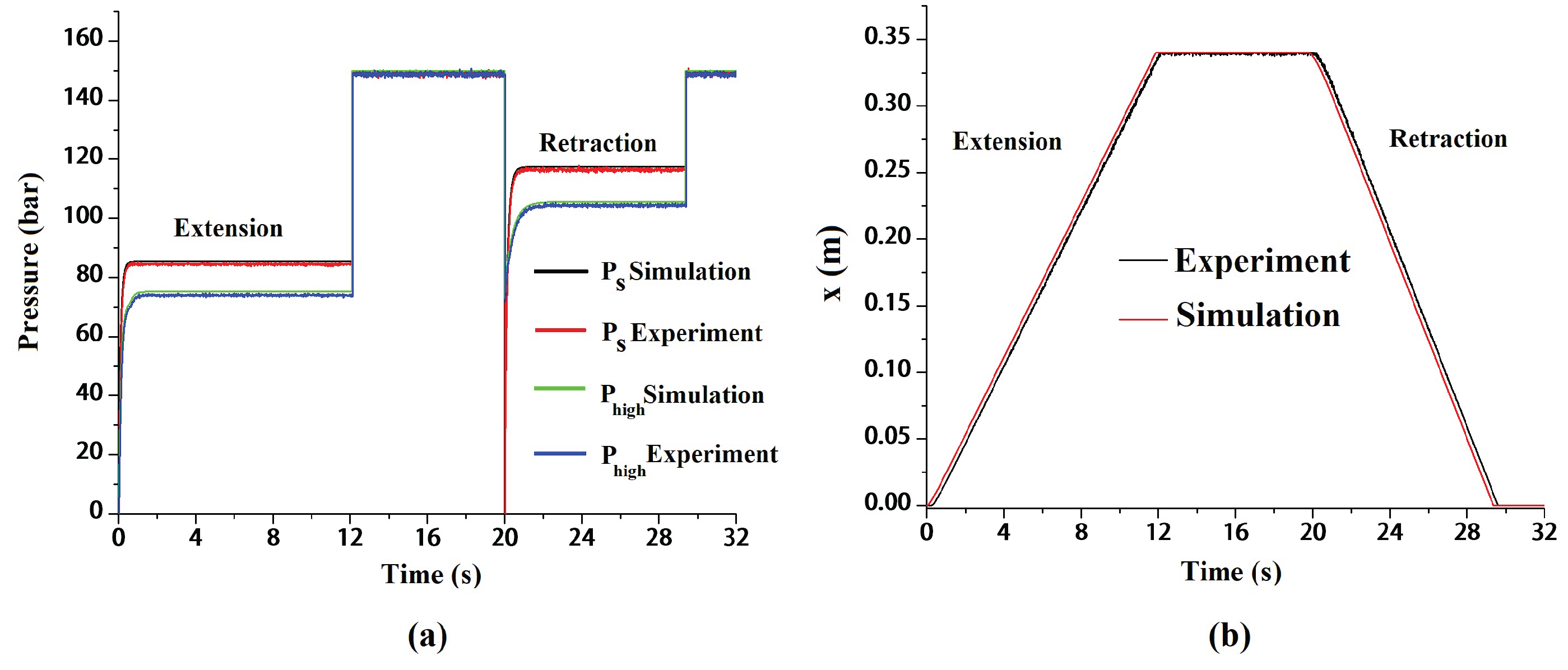
Figure 13a shows the experimental and simulation results of the pressures and , and Figure 13b shows the results of the cylinder position, respectively. Simulated values of and pressures are slightly lesser than the experimental values. The difference in simulated and experimental values varies approximately around in the range of 2 – 3 percentage for both and values. Restriction created in hydraulic hoses and higher leakage losses results in slightly higher pressure for the experimental values compared to simulation results. The cylinder position values are very closely accepted, and from the graph, it can be observed that the time consumed to complete the stroke in retraction is lesser than the extension side.
6. Conclusion and Future Work
In this article, the parametrization of the orbitrol valve driven by a stepper motor has been made. For carrying out the experimental work, an orbitrol valve-controlled hydraulic steering system is developed. Constant steering rates have been provided using a stepper motor connected to the steering column through a chain drive. PWM frequency signal input for the stepper motor and external load acting on the system are the inputs considered for the system to study. Experimental analysis has been carried out, and leakage response and flow characteristics of the valve under steady-state has been studied. For further analysis, a mathematically based simulation model has been developed in MATLAB Simulink environment. The results obtained through the simulation model has been validated successfully with the experimental results.
From the results, it can be deduced that the model developed is very well satisfying with the experimental results. As the difference in simulation and experimental values are not varying more than four percent of the reference values. Hence the simulation model developed is closely matching with the experimental ones. For a constant external load, the leakage flow is increasing with higher steering rate inputs. Whereas, for constant steering rate input, the valve’s leakage flow is not so significant with varying loads. Hence, it is almost behaving like a load sensing system. Thus, the article provides better insights about the orbitrol valve characteristics and helps to develop the orbitrol valve controlled automatic steering mechanism for the articulated vehicles. The future work of the article will be focusing on dynamic analysis and valve response analysis of the orbitrol valve. Further, applying different control strategies and their performance analysis for the steering cylinder’s automatic position control for the development of an automatic steering mechanism is a challenging task to perform.
Author Contributions
Conceptualization, A.K. and N.K.; methodology, S.R. and M.B.; software, S.R. and M.B.; validation, S.R.; formal analysis, S.R. and M.B.; investigation, S.R.; resources, N.K.; data curation, S.R. and M.B.; writing—original draft preparation, S.R.; writing—review and editing, S.R.,N.K., A.K. and M.B.; visualization, S.R.; supervision, N.K.; project administration, N.K.; funding acquisition, N.K. and A.K.. All authors have read and agreed to the published version of the manuscript.
Funding
Our sincere gratitude should go to the Department of Science & Technology, Government of India, for financial support to the research project (Ref. No.-SR/FST/ET-I/2018/180).
References
- Ei-Gindy, M.; Wong, J.Y. Steering response of articulated vehicles in steady-state turns; Technical report; SAE Technical Paper, 1985. [Google Scholar]
- Watton, J. Fluid power system. In Prentice Hall; 1989; pp. 317–319. [Google Scholar]
- Dasgupta, K.; Watton, J.; Pan, S. Open-loop dynamic performance of a servo-valve controlled motor transmission system with pump loading using steady-state characteristics. Mech. Mach. Theory 2006, 41, 262–282. [Google Scholar] [CrossRef]
- Dasgupta, K.; Mandal, S.; Pan, S. Dynamic analysis of a low speed high torque hydrostatic drive using steady-state characteristics. Mech. Mach. Theory 2012, 52, 1–17. [Google Scholar] [CrossRef]
- Kumar, N.; Dasgupta, K. Steady-state performance investigation of hydrostatic summation drive using bent-axis hydraulic motor. Proceedings of the Institution of Mechanical Engineers, Part C: Journal of Mechanical Engineering Science 2015, 229, 3234–3251. [Google Scholar] [CrossRef]
- Meng, F.; Tao, G.; Luo, P.P. Dynamic analysis of proportional solenoid for automatic transmission applications. In Proceedings of the 2014 International Conference on Mechatronics and Control (ICMC); IEEE, 2014; pp. 1120–1124. [Google Scholar]
- Amirante, R.; Bruno, S.; Del Vescovo, G.; Ruggeri, M. Improvement of a proportional valve dynamics by means of a peak and hold technique. In Proceedings of the Ninth Scandinavian International Conference on Fluid Power, Linköoping, June, 2005; pp. 1–3. [Google Scholar]
- Forental, V.; Forental, M.; Nazarov, F. Investigation of dynamic characteristics of the hydraulic drive with proportional control. Procedia Eng. 2015, 129, 695–701. [Google Scholar] [CrossRef]
- Ferrari, A.; Pizzo, P.; Rundo, M. Modelling and experimental studies on a proportional valve using an innovative dynamic flow-rate measurement in fluid power systems. Proceedings of the Institution of Mechanical Engineers, Part C: Journal of Mechanical Engineering Science 2018, 232, 2404–2418. [Google Scholar] [CrossRef]
- Bo, H.; Liang, W.; Yuefeng, D.; Zhenghe, S.; Enrong, M.; Zhongxiang, Z. Design and Experiment on Integrated Proportional Control Valve of Automatic Steering System. IFAC-PapersOnLine 2018, 51, 389–396. [Google Scholar] [CrossRef]
- Hiremath, S.; Kumar, R.K.; et al. Steady-state analysis of a precision hydraulic flow control servovalve using the finite element method. J. Micromechatronics 2006, 3, 103–122. [Google Scholar] [CrossRef]
- Zhang, Z.; Du, H.; Chen, S.; Huang, H. Frequency domain modeling, analysis and verification of electro-hydraulic servo steering system for heavy vehicles. Proc. Inst. Mech. Eng. Part D. J. Automob. Eng. 2020, 0954407020918696. [Google Scholar]
- Milecki, A.; Rybarczyk, D. Modelling of an electrohydraulic proportional valve with a synchronous motor. Stroj. Vestn.-J. Mech. Eng. 2015, 61, 517–522. [Google Scholar] [CrossRef]
- Vasile, L.; Vasiliu, N.; Călinoiu, C. Researches on the rotary valves of the hydraulic steering systems. relation 2006, 1, 7. [Google Scholar]
- Li, Y. Steady-state modelling and performance of a rotary direct drive digital valve. Meas. Control 2020, 0020294019866852. [Google Scholar]
- Yin, Y.; Rakheja, S.; Yang, J.; Boileau, P. Analysis of a flow volume regulated frame steering system and experimental verifications. SAE Technical Paper, Technical report. 2015. [Google Scholar]
- Zardin, B.; Borghi, M.; Gherardini, F.; Zanasi, N. Modelling and simulation of a hydrostatic steering system for agricultural tractors. Energies 2018, 11, 230. [Google Scholar] [CrossRef]
- Sreeharsha, R.; Kumar, N.; Kumar, A.; Tripathi, J. Modeling and analysis of articulated steering mechanism. Mater. Today Proc. 2022, 62, 3800–3803. [Google Scholar] [CrossRef]
- Sreeharsha, R.; Kumar, N.; Kumar, A. Automatic control and stability analysis of a novel stepper motor-driven orbitrol valve operated articulated steering mechanism. J. Braz. Soc. Mech. Sci. Eng. 2024, 46, 375. [Google Scholar] [CrossRef]
- Rowduru, S.; Bhola, M.; Kumar, N.; Kumar, A. Comparative Study on Performance and Energy-Efficient Operation of the Steering Valves Used in Articulated Steering System. J. Exp. Theor. Anal. 2025, 3, 26. [Google Scholar] [CrossRef]
- Ma, K.; Wang, J.; Gu, L. Experimental Study on Friction of Hydraulic Cylinder in Different Sealing Systems. Proc. MATEC Web Conf. EDP Sci. 2018, Vol. 153, 06012. [Google Scholar] [CrossRef]
Figure 1.
Hydraulic circuit diagram of orbitrol valve controlled steering system
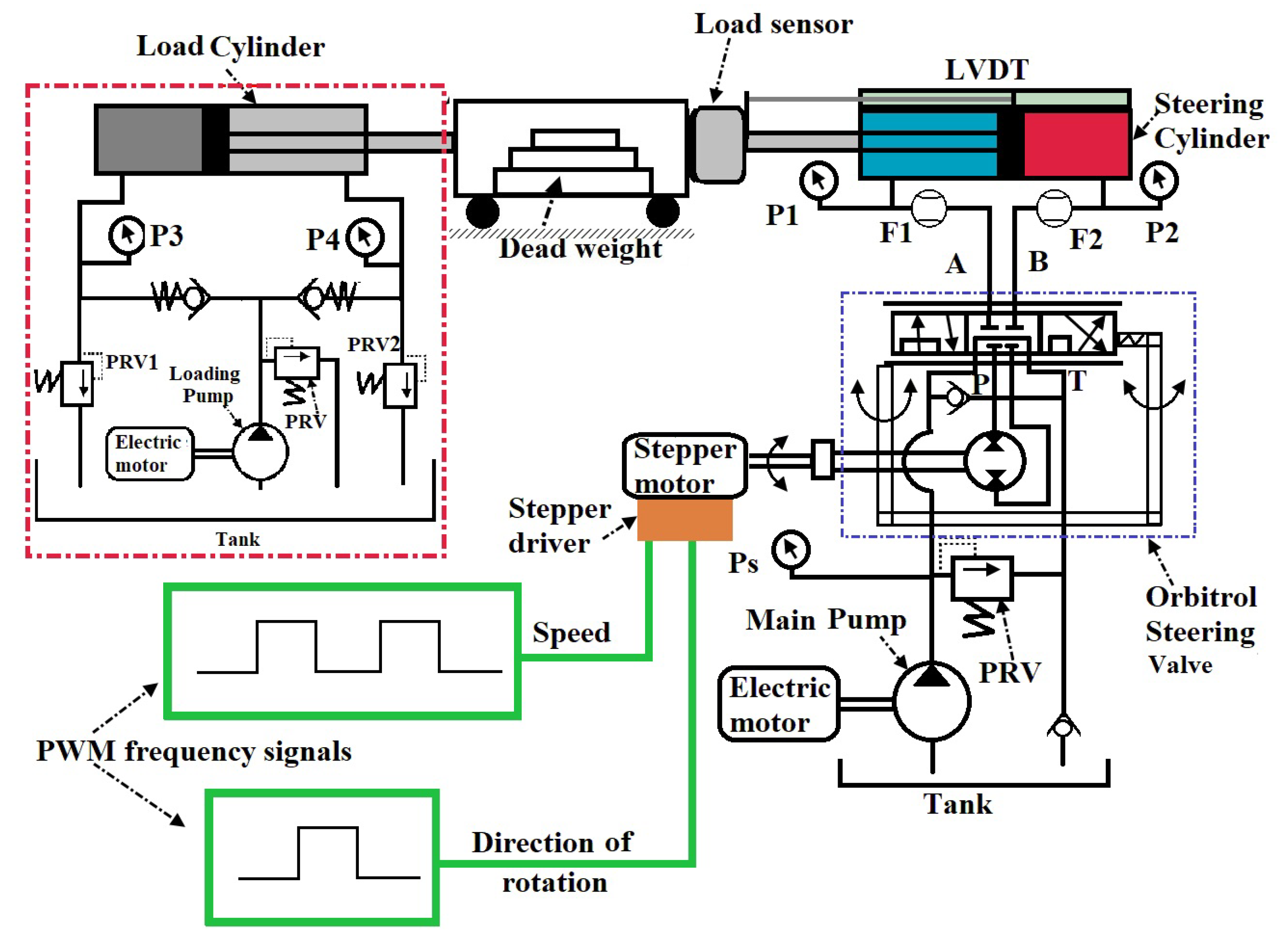
Figure 2.
Experimental setup of the proposed system
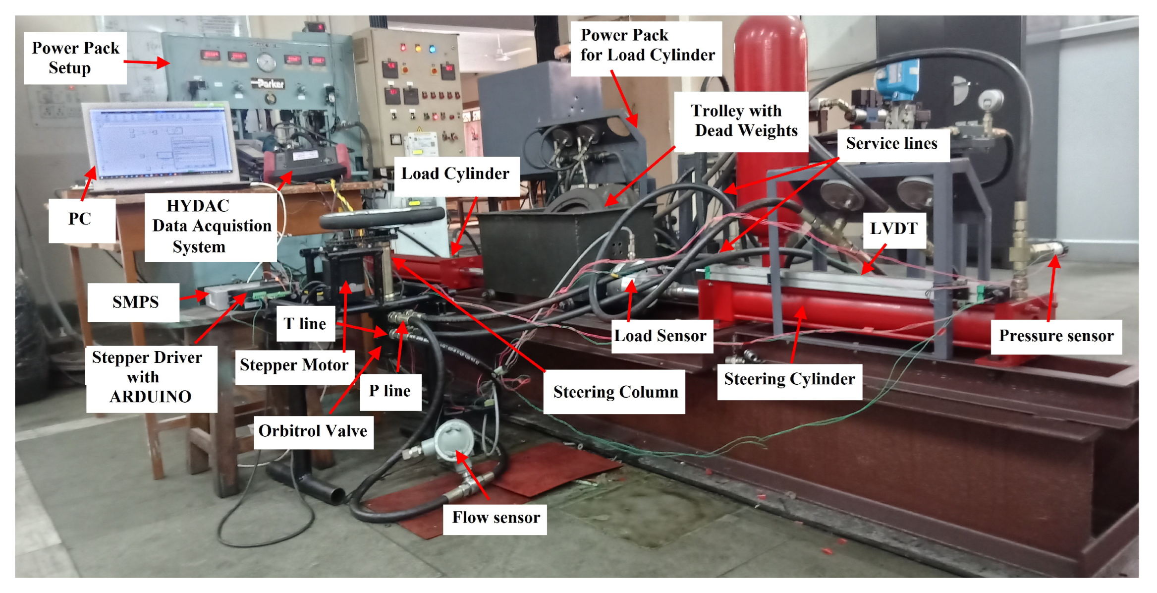
Figure 3.
Flow path in orbitrol valve during (i) Neutral condition and (ii) Steering Right condition.
Figure 3.
Flow path in orbitrol valve during (i) Neutral condition and (ii) Steering Right condition.
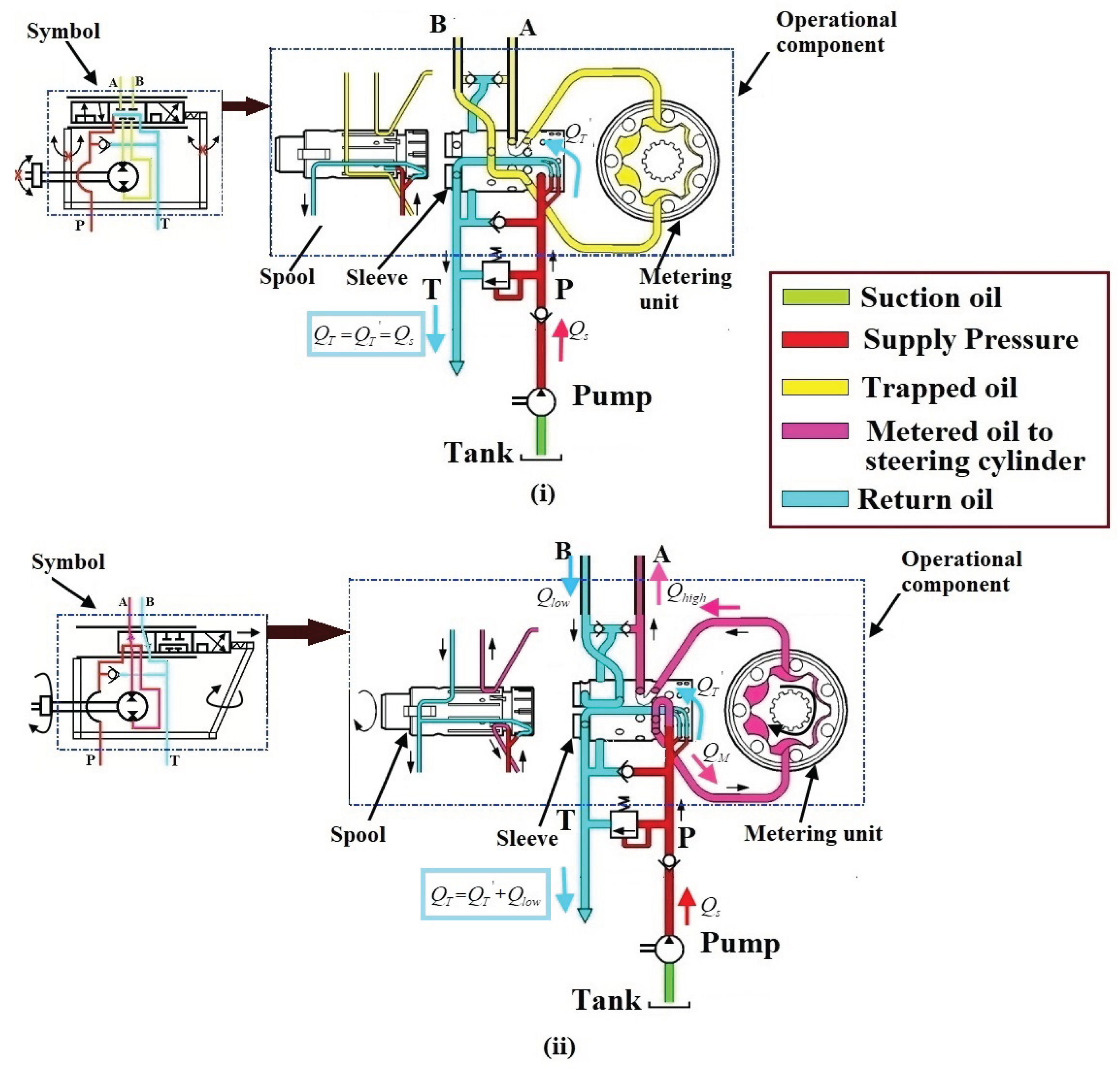
Figure 4.
Simulation model of the of orbitrol valve controlled steering system.
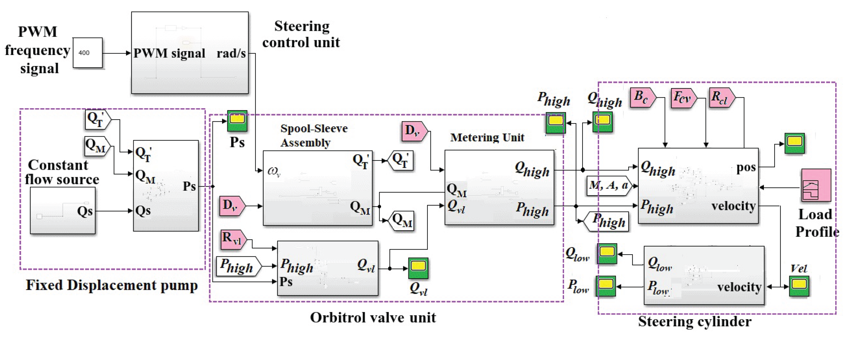
Figure 5.
Steady-state experimental values of the flow rate coming out of the valve
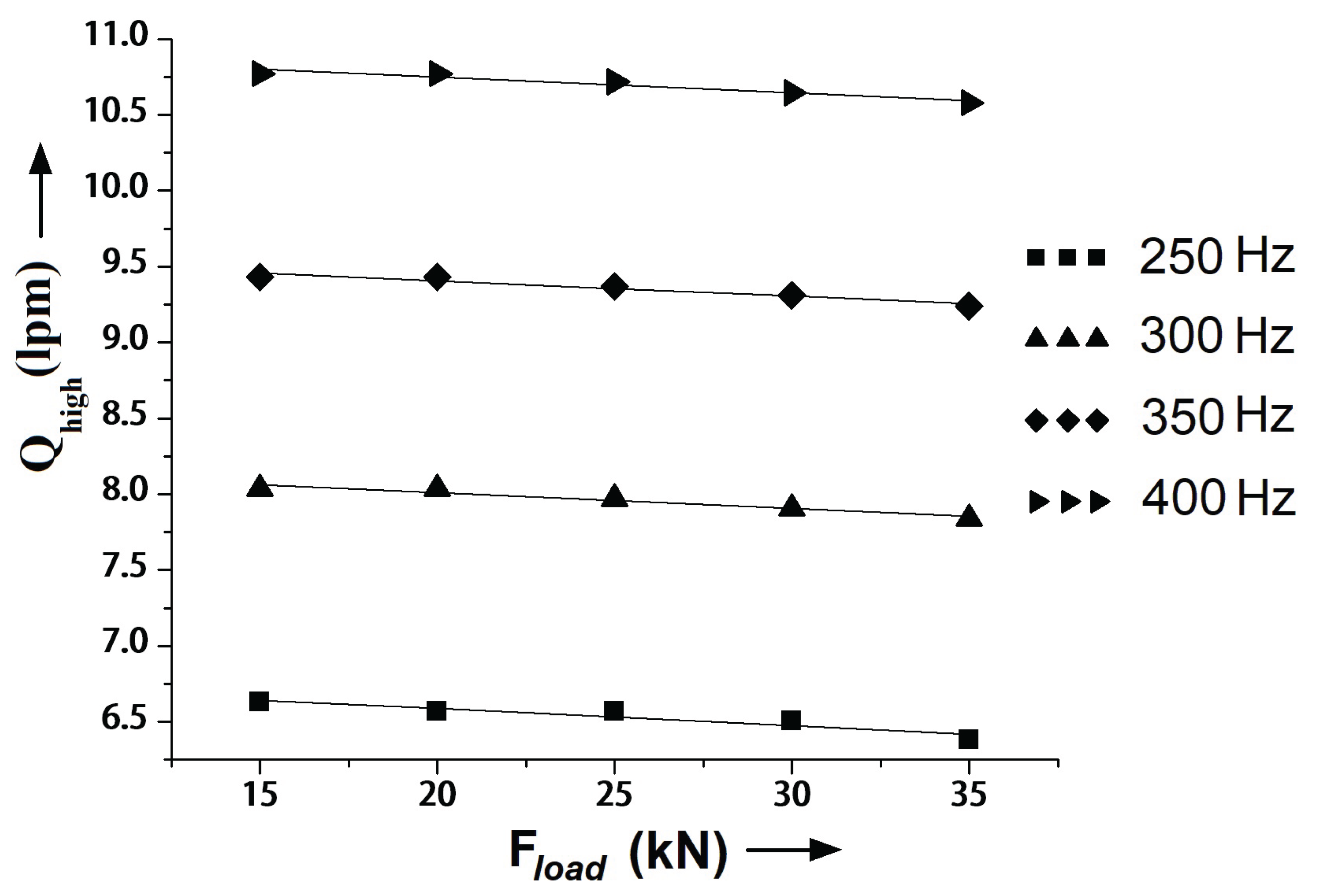
Figure 6.
Steady-state experimental values of the differential pressure across the valve vs. load.
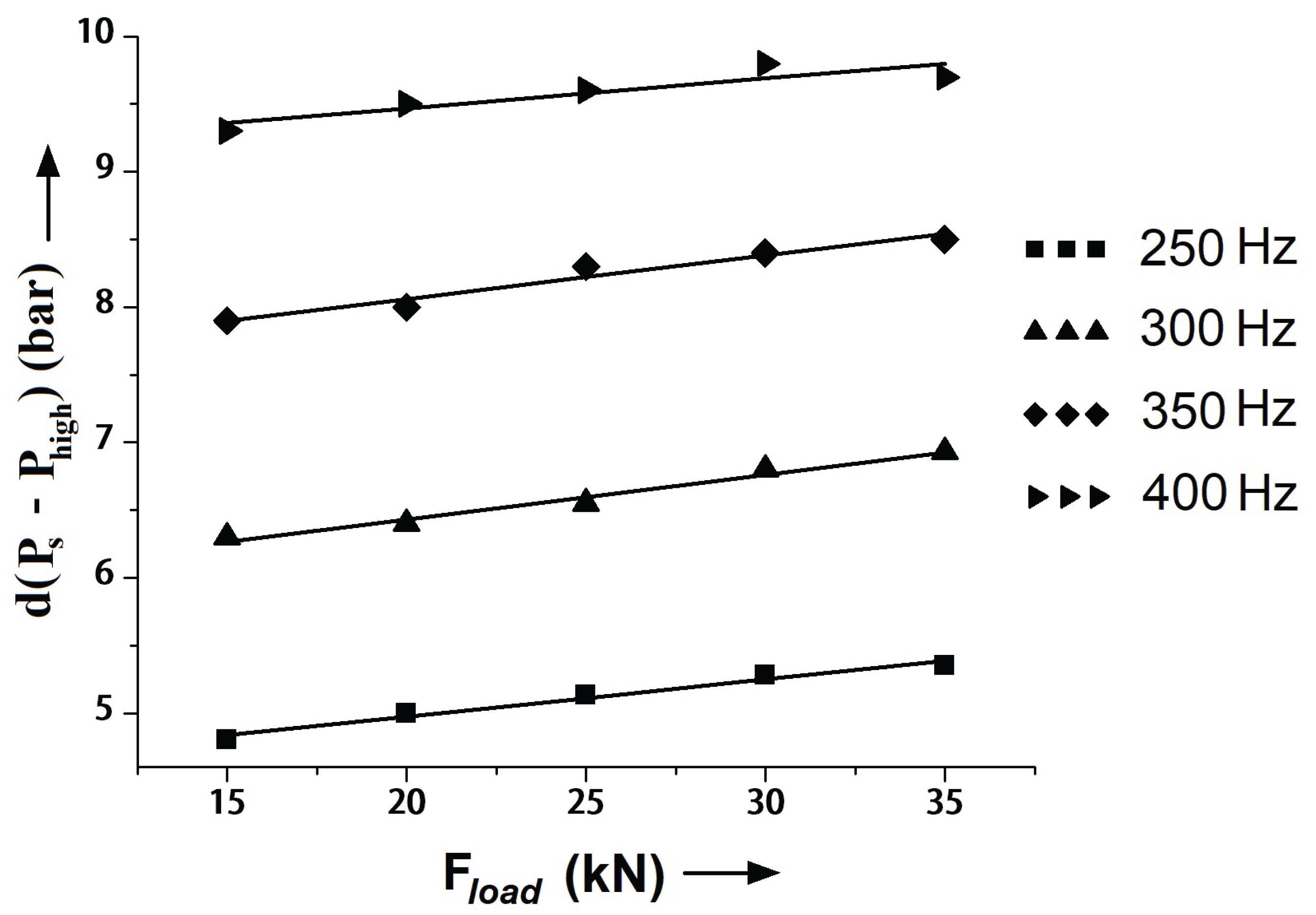
Figure 7.
Steady-state experimental leakage values of the orbitrol valve considered.
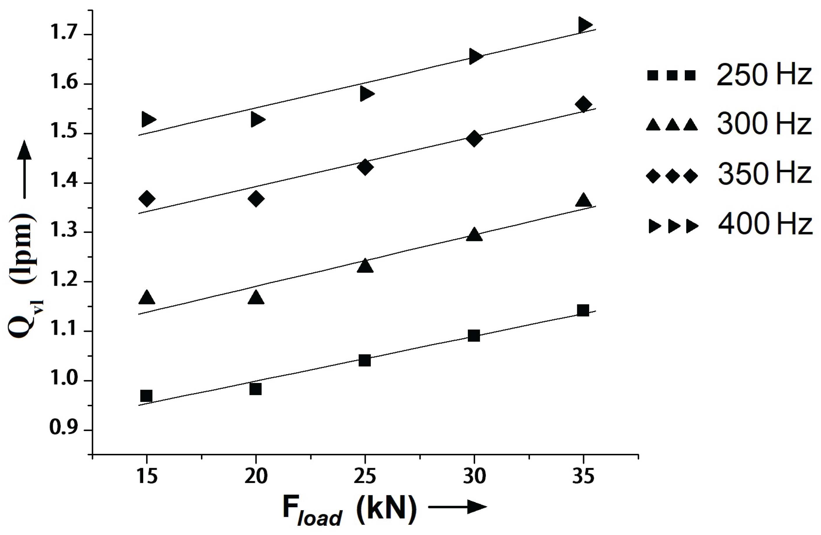
Figure 8.
Variation of leakage resistance of orbitrol valve with steering force and PWM frequency
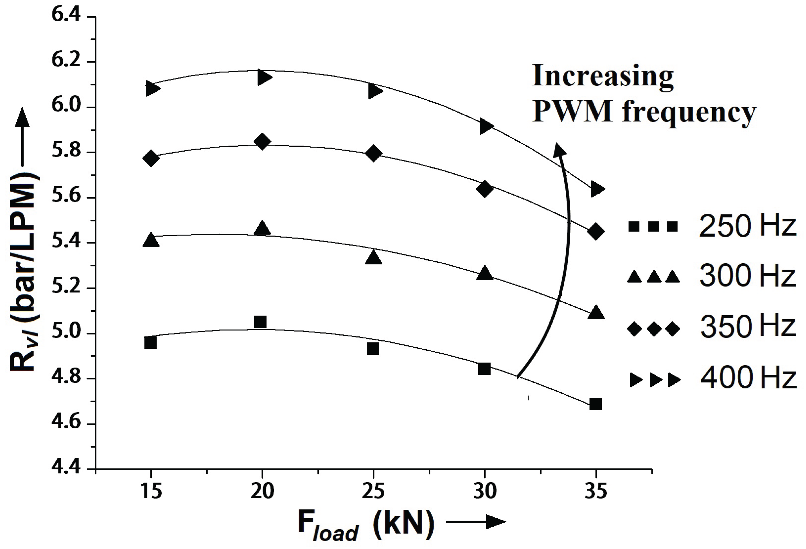
Figure 9.
Steady state steering torque and angular speed values of the stepper motor
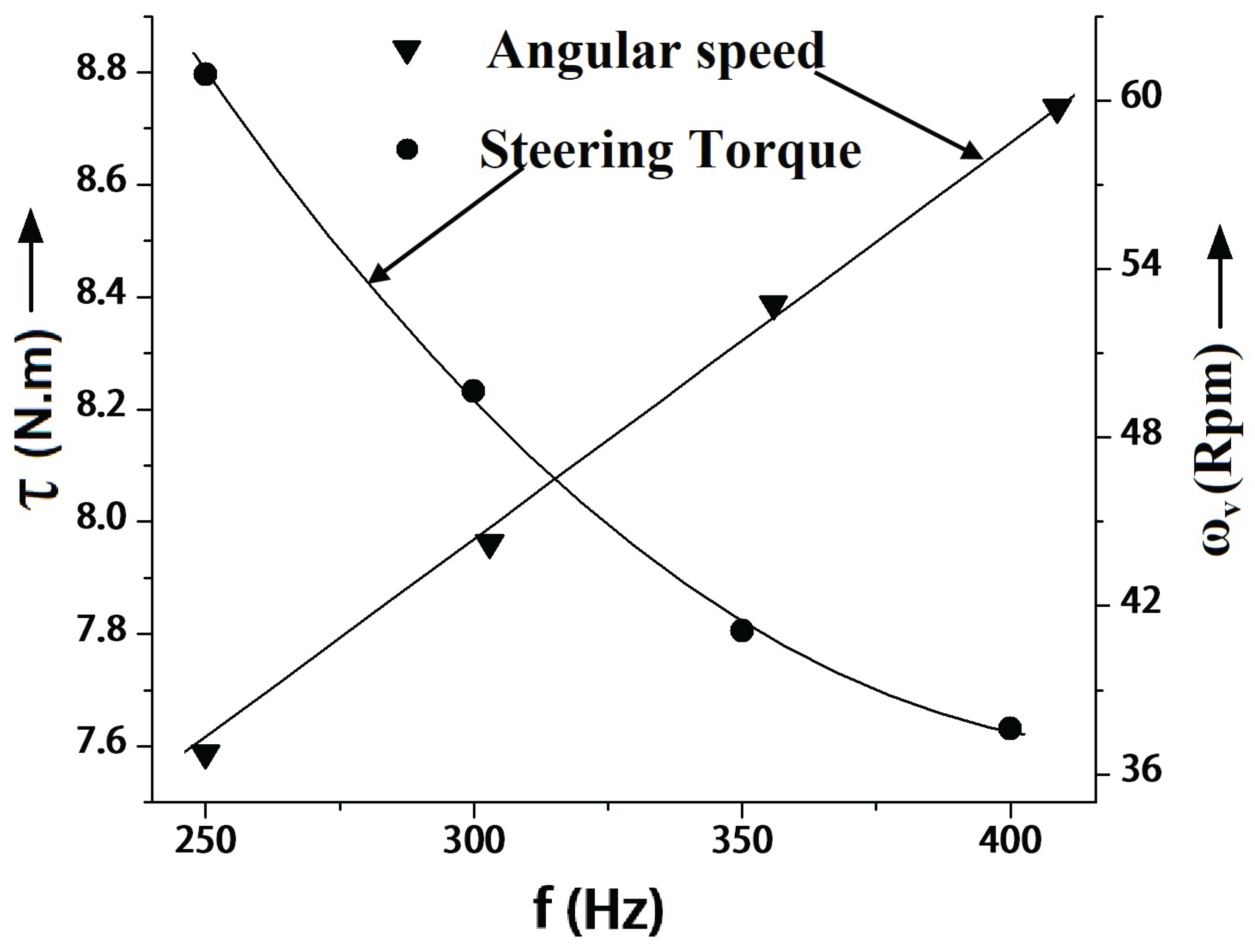
Figure 10.
Damping co-efficient of the hydraulic cylinder vs. external load for different frequencies
Figure 10.
Damping co-efficient of the hydraulic cylinder vs. external load for different frequencies
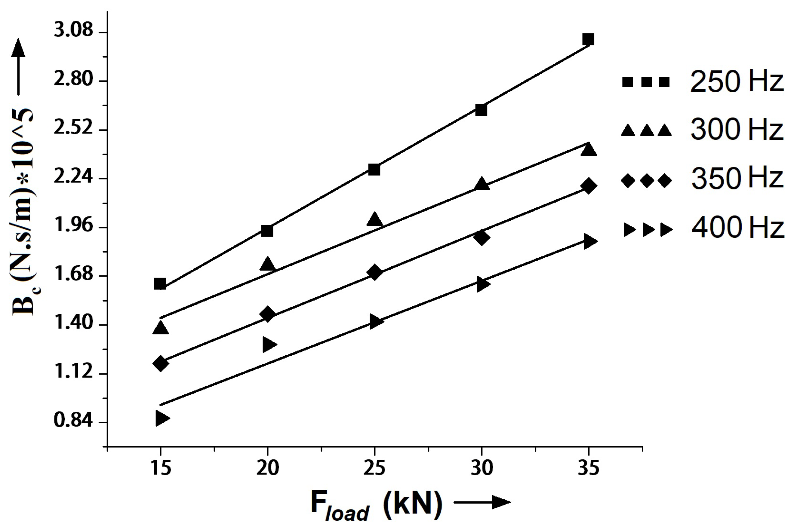
Figure 11.
Steady state steering torque and angular speed values of the stepper motor
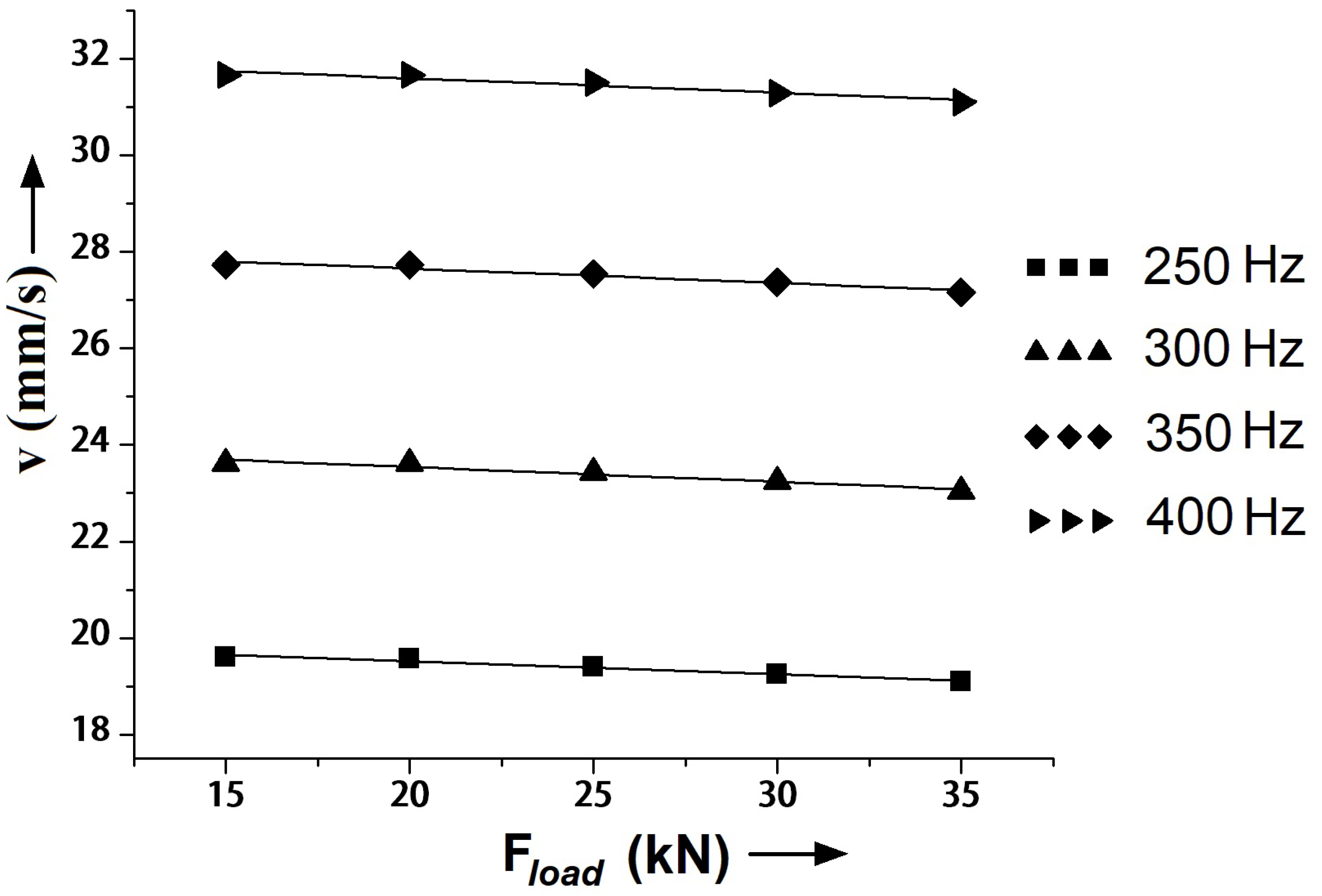
Figure 12.
Experimental vs simulation values of (a) flow rate coming out of the valve (b) Leakage flow rate at the valve
Figure 12.
Experimental vs simulation values of (a) flow rate coming out of the valve (b) Leakage flow rate at the valve
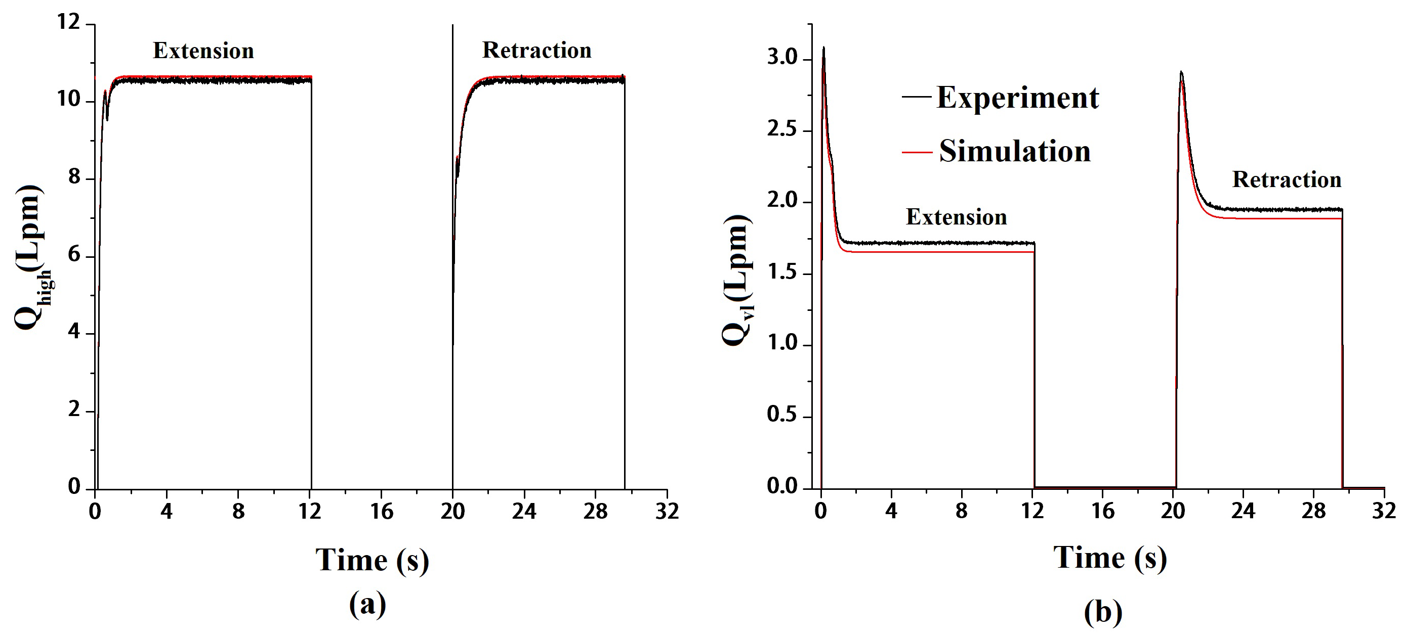
Figure 13.
Experimental vs simulation graphs of (a) Pressure across the valve; (b) Position of the steering cylinder
Figure 13.
Experimental vs simulation graphs of (a) Pressure across the valve; (b) Position of the steering cylinder
Disclaimer/Publisher’s Note: The statements, opinions and data contained in all publications are solely those of the individual author(s) and contributor(s) and not of MDPI and/or the editor(s). MDPI and/or the editor(s) disclaim responsibility for any injury to people or property resulting from any ideas, methods, instructions or products referred to in the content. |
© 2026 by the authors. Licensee MDPI, Basel, Switzerland. This article is an open access article distributed under the terms and conditions of the Creative Commons Attribution (CC BY) license (http://creativecommons.org/licenses/by/4.0/).
Copyright: This open access article is published under a Creative Commons CC BY 4.0 license, which permit the free download, distribution, and reuse, provided that the author and preprint are cited in any reuse.