

Submitted:
18 August 2026
Posted:
19 August 2026
You are already at the latest version
Abstract
The most promising class of optical gyroscope from the miniaturization point of view is the resonant optical gyroscope with a low-coherence radiation source. The present study briefly discusses the principles of operation of main types of such resonators. One of the most significant drawbacks of the resonant optical gyroscope with a low-coherence radiation source is its low energy efficiency. Only a small portion of the radiation carrying information about the angular velocity is directed from the source to the photodetector, specifically the radiation at frequencies corresponding to the eigenfrequencies of the ring resonator, the rest of the radiation being scattered on the unused ports of the resonator and converted into heat. It has been shown that the use of parallel-connected ring resonators can increase the energy efficiency of resonant gyroscopes with low-coherence radiation sources by an order of magnitude, from a few percent to tens of percent. It has also been theoretically demonstrated that this can reduce the contribution of shot noise and thermal noise of the photodiode by several times, and increase the sensitivity of the gyroscope.
Keywords:
resonant optical gyroscope
; resonator optical gyroscope
; Sagnac effect
; low-coherent source
; parallel-coupled ring resonators
1. Introduction
Nowadays a pronounced trend towards miniaturization is observed in different spheres of technology, including navigation systems and the inertial sensors used in them. Currently, research is being conducted to minimize the size of high-precision optical inertial sensors for angular velocity, such as optical gyroscopes. From the perspective of miniaturization, the most promising type of optical gyroscope is the resonant optical gyroscope [1,2,3,4]. The operation of all known optical gyroscopes, including resonant ones, is based on the Sagnac effect [5]. When a ring resonator rotates, the Sagnac effect causes a non-reciprocal shift of the frequency responses for waves passing through resonator in opposite directions (counterclockwise, CCW, and clockwise, CW). As a result, the difference in the eigenfrequencies of the ring resonator for CCW and CW waves, fS, will be proportional to the angular velocity of the passive ring resonator Ω [1]:
where MΩ – scaling factor; L – resonator optical length; λ0 – weight-average wavelength of the radiation source; A – ring resonator square. In optical resonance gyroscopes, the difference in the eigenfrequencies of the passive ring resonator fS is used as a measure of angular velocity Ω.
Starting with the first circuit implementations [6,7,8,9,10], the vast majority of optical resonance gyroscope circuits and prototypes use a high-coherence radiation source (laser). The laser radiation is divided into two channels directing light into a passive ring resonator in two opposite directions. The signal from the outputs of the passive ring resonator is used to match the emission frequencies of one (the so-called "basic" or "open" configuration [11,12]) or both channels ("closed" configuration [13,14]) with the eigenfrequencies of the resonator for CCW and CW directions. To match the channel frequencies, the built-in frequency stabilization/tuning system of the laser and additional phase and/or frequency modulator channels of the gyroscope system are used. In the "basic" configuration, the difference in eigenfrequencies and the corresponding angular velocity are determined by the magnitude of the signal at the output of the second channel (the channel with the unmatched frequency). In the "closed" configuration, they are determined based on the feedback signals required for frequency matching [1].
To date, prototypes of optical resonance gyroscopes with lasers as sources have achieved a fairly high accuracy: based on a silicon nitride waveguide resonator with a diameter of 35 mm, the bias drift, obtained through Allan's analysis, 13.2 °/h with an integration time of 1 h has been registered [15]; for a 51 mm fiber resonator, a bias drift of 0.02 °/h was achieved with an integration time of more than 2 h [16]; for a 60 mm fiber resonator, a bias drift of 1.23 °/h was achieved with an integration time of 5 s [17]. However, the commercial development of such gyroscopes, in addition to the problems associated with minimizing the influence of the main sources of errors, viz., backscattering, polarization fluctuations, and the optical Kerr effect, is hindered by the use of low-noise tunable lasers with a narrow line width Δf (10-200 kHz) in their setup [1]. Such lasers are relatively bulky and expensive, which makes it impossible to realize the potential of optical resonant gyroscopes.
The described problems can be avoided by using an alternative approach to construction of optical resonance gyroscopes base on low-coherence radiation sources (Δf of the order of units of THz, Δλ of the order of tens of nm). It was proposed at the end of the last century [18,19,20] and recently interest to it has been renewed and rapidly increased [21,22,23,24,25,26,27,28,29,30,31,32,33,34,35,36]. The change towards the low-coherence sources allows to design optical resonance gyroscopes with high reciprocity of optical channels and almost completely eliminate the influence of the main sources of measurement errors without using additional techniques, as well as it allows to use cheap and compact radiation sources similar to the commercial sources applied in interferometric fiber-optic gyroscopes. These factors procured the growth of scientific and practical interest in this approach. At the same time, one of the most significant drawbacks of optical resonance gyroscopes with low-coherence radiation sources, limiting the interest in their commercial development, is their low energy efficiency. Only a portion of the radiation carrying information about the angular velocity is directed from the source to the photodetector, specifically the radiation at frequencies corresponding to the eigenfrequencies of the resonator. The remaining radiation is emitted through unused ports of the resonator and is lost. As a result, the gyroscope utilizes only a few percent of the output power of the low-coherence radiation source. This leads to a number of technological problems, and also reduces the sensitivity of the gyroscope. In more detail, the principles of operation of optical resonance gyroscopes and the problem of their low energy efficiency are discussed in the next Section 2.
To struggle against this problem one can apply sensitive elements having a higher density of extremes in their spectrum, such as multi-ring resonators, ring confocal resonators, or whispering gallery mode resonators. This study focuses on the potential use of parallel-connected ring resonators. We discuss this type of resonator and expressions describing it in Section 3. These expressions are used in Section 4 for analysis of the results of using parallel-connected ring resonators in optical resonance gyroscopes with low-coherence radiation sources.
2. The Operating Principle and Energy Efficiency Problem of Optical Resonance Gyroscopes with Low-Coherence Radiation Sources
In resonant gyroscopes with low-coherence (broad-band) radiation sources, optical ring resonators operating in transmission mode (with two optical coupling loops) are used as sensitive elements. Such a resonator is a closed waveguide connected on two opposite sides by directional couplers 1 and 2 with the corresponding auxiliary waveguides (Figure 1a).
Radiation is introduced through the left or right end of one of the couplers and output through the corresponding end of the other coupler. It is obvious that in this case the transfer characteristics of the resonator (amplitude transmission coefficients) for the waves bypassing it against (tCCW) and clockwise (tCW) are equal, respectively [35]:
where fCCW,CW = f ± 0.5fS; f – radiation frequency; Κ1, и Κ2 – coupling factors of the directed couplers 1 and 2, respectively (the percentage of power, pumped from one waveguide to another when propagating the coupler); ρ – specific losses of fiber/waveguide of the ring resonator; exp(–ρl) = 1–Ρr; l = 2πR – геoметрическая длина резoнатoра; R – resonator radius; Ρr – the percentage of power lost by the wave upon a single passage of the resonator; j – imaginary unit; c – speed of light in vacuum. Figure 1b represents an example: moduli of amplitude transmission coefficient |tCCW| and |tCW| of the ring resonator based on the one-mode fiber at Κ1 = Κ2 = 0.05; Ρr = 0.01; R = 0.03 m. In the absence of the rotation the transfer characteristics of waves travelling in CCW and CW directions coincide. Upon rotation in accordance with the expression 1 they split by the magnitude fS.
Depending on the connection of the sensing element the resonant gyroscopes with low-coherent radiation sources are divided into two types: interference and filtering.
2.1. Interference Type
In the interference type, the radiation from the low-coherence source E0(f) is divided into two waves passing through the resonator, ECCW and ECW, which, respectively, pass through the resonator counterclockwise and clockwise. After the resonator, the waves pass through the modulators that shift their frequency by fm1 and fm2, respectively, and are directed to a photodetector:
where φ1 and φ2 – summarized phase shifts of the ECCW and ECW outside the resonator; P1 and P2 – fractions of the power lost be the ECCW и ECW outside the resonator.
Interference resonant gyroscopes with low-coherence radiation sources are designed so that the ECCW and ECW travel in the opposite directions but via the same optical path, thus, P1 = P2 = P and φ1 = φ2. Photodetector registers the result of the interference of the ECCW and ECW [22,33]:
In accordance with the expressions 2 and 3 the result of integration gives the following expression for the power of radiation on the photodetector:
where
PIn – input power of radiation (the power of the low-coherence radiation source); Δφ = φ1 – φ2 phase difference outside the resonator, normally it is equal to zero (if the gyroscope does not use non-reciprocal phase elements [4,23]); fN = Δfm + fS non-reciprocal frequency sift between the ECCW and ECW; Δfm = fm1 – fm2 non-reciprocal frequency sift created by the modulators.
Expression 5 determines the dependency of the power on the photodetector on the non-reciprocal frequency shift of the counter-propagating waves, which is caused, among other things, by the Sagnac effect. Graphically this dependency is demonstrated in Figure 2 (dashed-dotted line) for the following gyroscope parameters: PIn = 1 mW; Δφ = 0; P = 0; single-mode fiber resonator with R = 0.03 m; Κ1= Κ2= 0.05; Pr = 0.01; FSR = c/L is the free spectral range of the resonator. As the modulus of the angular velocity Ω increases, the power POutI is decreasing. This allows the electronic gyroscope system to determine the angular velocity proportional to fS. At the same time, from Figure 2 and expressions 1 and 5, it is obvious that with the modulators turned off (Δfm=0), the sensitivity to angular velocity is minimal and the gyroscope is not able to determine the direction of rotation, viz., the sign of the angular velocity. To reach the steepest and minimally nonlinear section of the POutI(fN) and to determine the direction of rotation in interference resonant gyroscopes with low-coherence radiation sources, various approaches are used: variable frequency bias created by modulators [21,22,23,24,25]; in addition to the variable frequency bias, a quasi-static non-reciprocal frequency shift is used, which compensates for the fS shift caused by the Sagnac effect (This allows for a complete linearization of the output characteristic) [26,27,36]; non-reciprocal phase elements are used, which introduce a non-zero Δφ, which changes the shape of the characteristic POutI(fS) [29].
2.2. Filtering Type
The filtering type gyroscope is based on the filtering of radiation by a passive ring resonator when it is passed in two opposite directions. First, the radiation from a low-coherence source is introduced into the resonator and passes it in the first direction (for example, in the CCW direction). After passing through the resonator, the radiation passes through modulators, is frequency-shifted by fm, and is directed back to the resonator using a mirror [18,19,20] or a fiber circulator [30,31,32]. The radiation is then re-introduced into the resonator and passes through it in the second direction (in the example, in the CW direction). After the second pass through the resonator, the radiation is directed to the photodetector [20,30]:
where S(f) – normalized spectral profile of the low-coherence radiation source ( ∫S(f)df = 1); TCCW,CW = |tCCW,CW |2 – energy transmission coefficients of the resonator for the CCW and CW directions; P – fraction of power lost by a wave outside the resonator; fN = fm + fS non-reciprocal frequency shift between transmission coefficients of the resonator when it is passed in two opposite directions.
Graphically the dependence of the photodetector power on the non-reciprocal frequency shift for the filtering type is shown in Figure 2 (solid line) with the following gyroscope parameters: PIn = 1 mW; P = 0; single-mode fiber resonator with R = 0.03 m; Κ1= Κ2= 0.05; Pr = 0.01. Here, variable frequency bias is used to reach the steepest section of the POutF(fN), and a quasi–constant non-reciprocal frequency shift, compensating for the fS shift caused by the Sagnac effect. This allows for linearization of the output characteristic.
As can be seen from Figure 2, the sections with the maximum slope of POutF(fN) and POutI(fN) are periodically repeated and arranged in pairs and symmetrically around fN = i·FSR, where i is an integer. In resonant gyroscopes with low-coherence radiation sources, the symmetric sections near fN = 0 are usually used as the working sections of the of POutF(fN) and POutI(fN) characteristics (see Figure 2b) [20,21,22,23,24,25,30,31,32,33]. Therefore, further we will consider only these working sections.
2.3. The Problem of Low Energy Efficiency
As can be seen from Figure 2, in both types of resonant gyroscopes with low-coherence radiation sources, only a few percent of the source power is utilized. This leads to a number of technological issues. For example, it becomes necessary to use light sources that are an order of magnitude more powerful. In this case, the source noise increases and/or larger-sized sources must be used. Furthermore, the vast majority of the source power is not directed to the photodetector as a useful signal but is instead dissipated at the unused ports of the ring resonator and converted into heat. This increases the thermal instability of the gyroscope. As a result, the combination of technological problems caused by the low energy efficiency of resonant gyroscopes with low-coherence light sources hinders the development of commercially successful prototypes.
Thus, the task of improving the energy efficiency of these gyroscopes becomes urgent. Obviously, in solving this problem, it is also desirable to improve, or at least maintain, the accuracy characteristics of the gyroscope. The ultimate sensitivity of resonant gyroscopes with low-coherence light sources, δΩ (the minimum change in angular velocity that can potentially be measured against fundamentally irremovable noise), is limited by the noise at the photodetector (photodiode) [37].
where iRIN is the noise caused by laser intensity noise [4,38]; id is shot noises [39,40]; it is thermal noise (Johnson–Nyquist noise) [40]; iPD = sPOut is the photodiode current; s = (eη)/(hf) is the photodiode responsivity; e is the electron charge; η is the quantum efficiency; h is Planck's constant; POut = TPIn is the optical power at the photodiode; T is the power transmission coefficient of the optical system; RIN is the relative intensity noise of the laser; k is Boltzmann's constant; t is the temperature in Kelvin; Rl is the load resistance; and F is the photodiode bandwidth.
In practice, in resonant gyroscopes with low-coherence radiation sources, iRIN usually dominates [4,22]. Therefore, when increasing the energy efficiency, and hence the corresponding increase in T, it is desirable to prevent a decrease in the parameter . This is possible if the increase in energy efficiency is accompanied by a comparable increase in p2 = max(|dT/dfS|) – the slope of the gyroscope output characteristic at its operating point. Theoretically, there are methods for compensating iRIN, which make it possible to reduce its level below id [22,41]. At the same time, shot noise cannot be fundamentally eliminated. Therefore, to improve the ultimate sensitivity, it is also important to ensure an increase in the parameter . It is also obvious that an increase in p2 makes it possible to proportionally increase the gyroscope sensitivity and reduce the contribution of the photodiode thermal noise.
3. Parallel-Coupled Ring Resonators
Optical parallel-coupled ring resonators consist of two or more ring resonators integrated into a single system through coupling with auxiliary waveguides [42,43]. Such resonators are also often referred to as side-coupled integrated spaced sequence of resonators (SCSSOR) [44]. Within the framework of this study, of interest are their configurations operating in transmission, in which each resonator is connected on two opposite sides to identical auxiliary waveguides (Figure 3).
Let us define the transfer function of a system of n parallel-coupled ring resonators operating in transmission as tn. The resonators are coupled to the auxiliary waveguides via directional couplers (through optical tunneling). Let the radiation be introduced into the system through the left end of the lower auxiliary waveguide and extracted through the left end of the upper auxiliary waveguide. Let us denote the electric field amplitudes in the lower waveguide to the left of the coupler of the k-th resonator (at its input), in the upper waveguide to the left of the coupler of the k-th resonator (at its output), in the k-th resonator to the right of the lower coupler, and in the k-th resonator to the left of the upper coupler as Ak, Bk, Ck and Dk, respectively. In this case, the following relations hold:
where ; κ1k and κ2k are the amplitude coupling coefficients of the k-th resonator with the lower and upper auxiliary waveguides, respectively; j is the imaginary unit; exp(–jψk) is the field transformation (phase and amplitude change) upon a single round trip of the wave in the k-th resonator; ψk = 2π(f + fS)Lk/c – jρklk/2; for the opposite direction of circulation in the resonator (clockwise), the sign before fS changes to minus; lk and Lk are the length and optical length of the k-th resonator, respectively; ρk is the energy loss per unit length for the k-th resonator; exp(–jφk) is the field transformation (phase and amplitude change) when the wave propagates through the section of the auxiliary waveguide between adjacent resonators; φ = 2πfLw/c – jρwlw/2; lw and Lw are the length and optical length of the waveguide section between adjacent resonators; ρw is the energy loss per unit length of the auxiliary waveguide.
Using expression (7), the fields at the input and output of the (k+1)-th and k-th resonators can be related through the resonator matrix mk:
The last resonator of the system is the n-th resonator. Therefore, for its matrix mn, we assume that lw = 0. Let us also denote the electric field amplitudes at the right end of the lower and upper couplers of the n-th resonator (at the right ends of the auxiliary waveguides) as An+1 and Bn+1, respectively. It is evident that:
where M is the product of the matrices of all n resonators. Since no radiation is introduced into the system through the right end of the upper auxiliary waveguide, Bn+1 = 0. In this case, from expression (9), the transfer function of the system of n parallel coupled ring resonators can be readily expressed as:
where M1 and M2 are the corresponding elements of the matrix M.
Within the framework of this work, of interest are optical parallel coupled ring resonators with an equidistant spectrum. Obviously, this requires the optical lengths of the resonators to be chosen as follows: Lk = L1 + (k – 1)λ0/n, where L1 is the optical length of the first ring resonator; λ0 is the weighted average wavelength of the radiation source. Figure 4 shows examples of the magnitudes of the transfer functions of parallel-coupled ring resonators under the above condition and with the following parameter values: R1 = 0.03 m; κ1k = κ2k = √Κ; Κ = 0.05; ρk = ρw = ρ; Pr = 0.01; Lw = 0.5L1; Ω = 0; λ0 = 1.55 μm.
4. Improving the Energy Efficiency of Optical Resonant Gyroscopes with Low-Coherence Light Sources
As can be seen from Figure 4, the transfer functions of parallel-coupled ring resonators have n times more extrema than single-ring resonators. This makes it possible to increase the fraction of the radiation source power directed to the photodetector of the gyroscope. To analyze the improvement in energy efficiency of resonant gyroscopes with low-coherence light sources when using parallel-coupled ring resonators, their filtering and interference types were simulated. When determining the output radiation powers POutI and POutF in expressions (4) and (6), respectively, the transfer functions of parallel coupled ring resonators for the CCW and CW waves were substituted (using expressions (8)–(10)). Figure 5 shows examples of POutI and POutF when using one, two, three, and four resonators – POutI1 and POutF1, POutI2 and POutF2, POutI3 and POutF3, POutI4 and POutF4, respectively. In the example, the following model parameter values were set: PIn = 1 mW; P = 0; R = 0.03 m; κ1k = κ2k = √Κ; Κ = 0.05; ρk = ρw = ρ; Pr = 0.01; Lw = 0.5L1; λ0 = 1.55 μm.
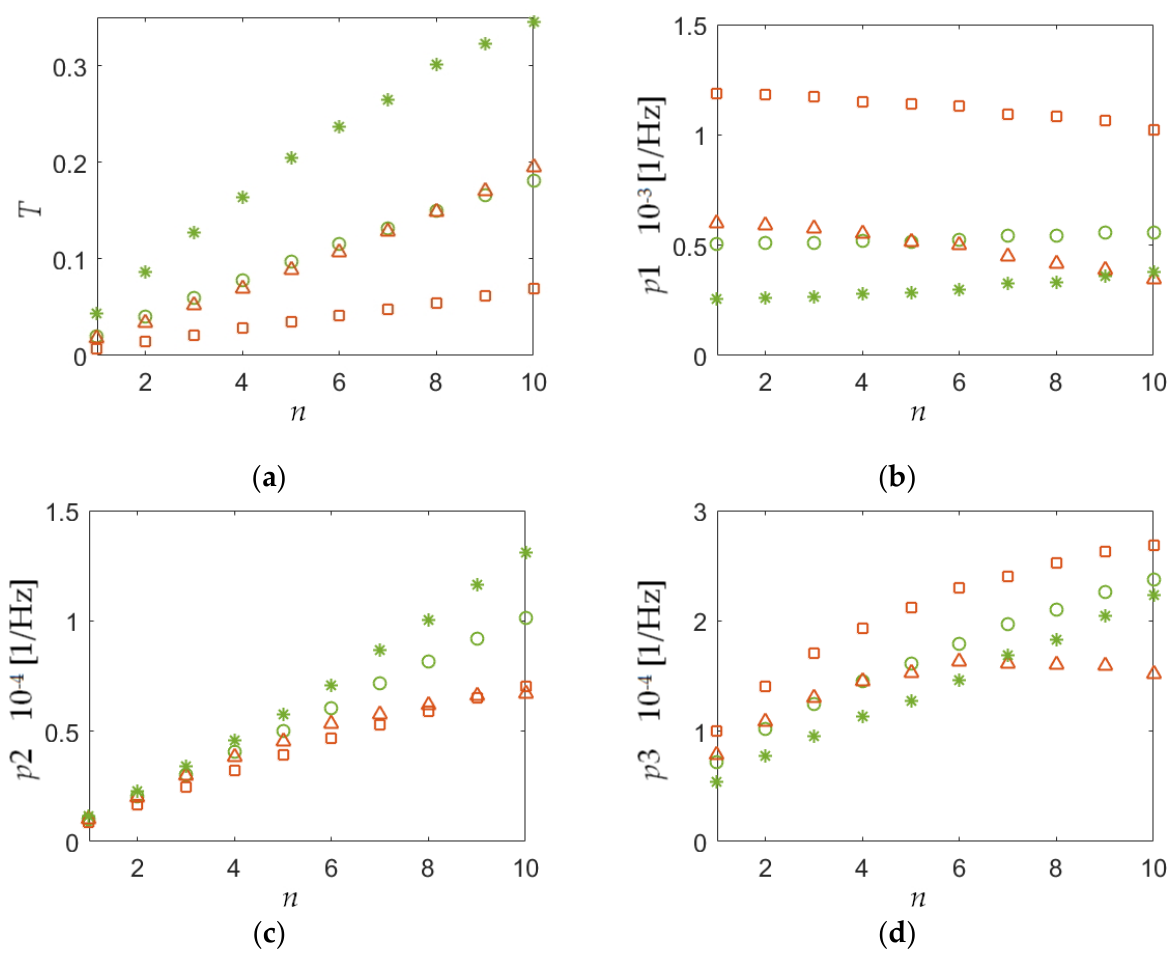
As is noted in Section 2, due to the variable frequency bias, gyroscopes operate in the domains of the output characteristics corresponding to their maximum slope, i.e., at max(|POut/dfN|). Therefore, the energy efficiency of the gyroscopes is proportional to the power transmission coefficient T of the optical system at frequencies corresponding to max(|POut/dfN|). These values of the coefficient T, as well as the parameters p1, p2 and p3 for gyroscopes of the filtering type (marked in red) and the interference type (marked in green) are shown in Figure 6. In this case, the input parameters of the model were the same as those specified at the beginning of the Section, except for the coefficients Κ. For the graphs marked with squares and circles, Κ = 0.05, and for those marked with triangles and stars, Κ = 0.1.
It can be seen (Figure 6a) that the use of parallel-coupled ring resonators makes it possible to increase the energy efficiency of resonant gyroscopes with low-coherence radiation sources by an order of magnitude – from units to tens of percent. Moreover, with an increase in T, a comparable relative increase is observed in the slope of the gyroscope output characteristic at its operating point – the parameter p2 (Figure 6c). This leads to a proportional increase in sensitivity and a reduction in the contribution of the photodiode thermal noise. With an increase in the number of resonators n, the value of p1 remains relatively stable, and the contribution of RIN noise does not change significantly: in the filtering-type gyroscope, the RIN noise contribution increases slightly, while in the interference-type it decreases (Figure 6b). Furthermore, the use of parallel coupled ring resonators can also increase the value of p3, which reduces the contribution of shot noise (Figure 6d). It is worth noting that the energy efficiency of resonant gyroscopes with low-coherence light sources can also be improved by increasing the coupling coefficients Κ of their directional couplers. At the same time, the sensitivity of the interference-type gyroscope also increases somewhat (Figure 6c). However, as can be seen from Figure 6b, this sharply increases the already typically dominant contribution of RIN noise: when Κ is increased from 0.05 to 0.1, the noise contribution doubles. In this case, the contribution of shot noise also increases (Figure 6d). Therefore, when optimizing the gyroscope design, an increase in the coupling coefficient Κ should be approached with caution.
5. Conclusions
From the standpoint of miniaturization, the most promising type of optical gyroscope is the resonant optical gyroscope. The use of low-coherence light sources in such gyroscopes makes it possible to: design optical resonant gyroscopes with high reciprocity of the optical channels; almost completely eliminate the influence of the main measurement error sources without the use of additional techniques; use inexpensive and compact light sources similar to commercially available sources used in interferometric fiber-optic gyroscopes. At the same time, one of the most significant drawbacks of optical resonant gyroscopes with low-coherence light sources is their low energy efficiency.
An analysis of the operating principles of these gyroscopes has shown that this problem can be solved by using, as sensitive elements, those types of ring resonators that are characterized by a higher density of extrema in the spectrum. The use of parallel-coupled ring resonators makes it possible to increase the energy efficiency of resonant gyroscopes with low-coherence light sources by an order of magnitude – from units to tens of percent. This also makes it possible to reduce the contribution of shot noise and photodiode thermal noise by several times, as well as to increase the sensitivity of the gyroscope. In the future, it is planned to experimentally test the results obtained in this study, as well as to consider the prospects of using other types of ring resonators characterized by a high density of extrema in the spectrum in resonant gyroscopes with low-coherence light sources. For example, more complex types of multiring resonators, ring confocal resonators, and the suchlike.
Author Contributions
Conceptualization, methodology, resources Yu.V.F. and V.Yu.V.; investigation and formal analysis A.V.G. and E.V.S.; writing—original draft preparation E.V.S. and A.V.V.; formal analysis, supervision, project administration, and funding acquisition Yu.V.F. and V.Yu.V.; writing—review and editing, validation V.Y.V. All authors have read and agreed to the published version of the manuscript.
Funding
This work was partially supported by the Ministry of Science and Higher Education of the Russian Federation (State Assignment project, grant # FSEE-2025-0008)
Conflicts of Interest
The authors declare no conflict of interest.
References
- Venediktov, V.Y.; Filatov, Y.V.; Shalymov, E.V. State-of-the-art optical resonator gyroscopes. Gyroscopy Navig. 2023, 14, 27–35. [Google Scholar] [CrossRef]
- Sun, C.; Yan, B.; Qi, Y.; et al. Resonant integrated optical gyroscope with an ultra-high Q value SOI resonant ring. Opt. Express 2025, 33, 29764–29774. [Google Scholar] [CrossRef] [PubMed]
- Wang, S.; Liu, W.; Tao, Y.; et al. A novel highly sensitive angular rate sensor employing anti-parity-time symmetry. J. Light. Technol. 2024, 42, 3884–3890. [Google Scholar] [CrossRef]
- Wang, Y.; Yang, L.; Xu, C.; et al. Broadband source-driven resonant integrated optical gyroscope using a low modulation frequency. Opt. Express 2025, 33, 36172–36181. [Google Scholar] [CrossRef] [PubMed]
- Malykin, G.B. The Sagnac effect: correct and incorrect explanations. Phys. Usp. 2007, 43, 1229. [Google Scholar]
- Ezekiel, S.; Balsamo, S.R. Passive ring resonator laser gyroscope. Appl. Phys. Lett. 1977, 30, 478. [Google Scholar] [CrossRef]
- Sanders, G.A.; Prentiss, M.G.; Ezekiel, S. Passive ring resonator method for sensitive inertial rotation measurements in geophysics and relativity. Opt. Lett. 1981, 6, 569–571. [Google Scholar] [CrossRef] [PubMed]
- Meyer, R.E.; Ezekiel, S.; Stowe, D.W.; et al. Passive fiber-optic ring resonator for rotation sensing. Opt. Lett. 1983, 8, 644–646. [Google Scholar] [CrossRef] [PubMed]
- Ohtsu, M.; Araki, S. Using a 1.5-μm DFB InGaAsP laser in a passive ring cavity-type fiber gyroscope. Appl. Opt. 1987, 26, 464–470. [Google Scholar] [CrossRef] [PubMed]
- Ezekiel, S.; Cole, J.A.; Harrison, J.; et al. Passive cavity optical rotation sensor. Proc. Soc. Photo-Opt. Instrum. Eng. 1978, 157, 68. [Google Scholar] [CrossRef]
- Zhang, X.; Ma, H.; Jin, Z.; et al. Open-loop operation experiments in a resonator fiber-optic gyro using the phase modulation spectroscopy technique. Appl. Opt. 2006, 45, 7961–7965. [Google Scholar] [CrossRef] [PubMed]
- Strandjord, L.K.; Sanders, G.A. Resonator fiber optic gyro employing a polarization-rotating resonator. Proc. SPIE 1992, 1585, 163–172. [Google Scholar] [CrossRef]
- Jin, Z.; Yu, X.; Ma, H. Closed-loop resonant fiber optic gyro with an improved digital serrodyne modulation. Opt. Express 2013, 21, 26578–26588. [Google Scholar] [CrossRef] [PubMed]
- Ma, H.; Zhang, J.; Wang, L.; et al. Double closed-loop resonant micro optic gyro using hybrid digital phase modulation. Opt. Express 2015, 23, 15088–15097. [Google Scholar] [CrossRef] [PubMed]
- Feng, C.; Zhang, Y.; Ma, H.; et al. Improving long-term temperature bias stability of an integrated optical gyroscope employing a Si₃N₄ resonator. Photonics Res. 2022, 10, 1661–1668. [Google Scholar] [CrossRef]
- Strandjord, L.K.; Qiu, T.; Salit, M.; et al. Improved bias performance in resonator fiber optic gyros using a novel modulation method for error suppression. In Proceedings of the 26th International Conference on Optical Fiber Sensors, Lausanne, Switzerland, 24–28 September 2018. [Google Scholar]
- Liu, L.; Li, H.; Liu, S.; et al. Suppressing backscattering noise of a resonant fiber optic gyroscope using coherent detection. Appl. Opt. 2022, 61, 4421–4428. [Google Scholar] [CrossRef] [PubMed]
- Novikov, M.A.; Ivanov, V.V. Optical gyroscope with passive ring resonator. RU Patent 2124185, 1999. [Google Scholar]
- Novikov, M.A.; Ivanov, V.V. Resonant ring interferometry using incoherent light. Tech. Phys. Lett. 1998, 24, 24–29, (in Russian: Rezonansnaya kol cevaya interferometriya na nekogerentnom svete). [Google Scholar] [CrossRef]
- Ivanov, V.V.; Novikov, M.A.; Gelikonov, V.M. Observation of the Sagnac effect in a ring resonant interferometer with a low-coherence light source. Quantum Electron. 2000, 30, 119–124. [Google Scholar] [CrossRef]
- Wang, Y.; Li, B.; Liu, S.; et al. Quadrature demodulation with a synchronous difference for broadband source-driven resonant fiber-optic gyroscopes. Appl. Opt. 2024, 63, 6413–6418. [Google Scholar] [CrossRef]
- Zhao, S.; Liu, Q.; Liu, Y.; et al. Navigation-grade resonant fiber-optic gyroscope using ultra-simple white-light multibeam interferometry. Photonics Res. 2022, 10, 542–549. [Google Scholar] [CrossRef]
- Liu, S.; Liu, L.; Hu, J.; et al. Reduction of relative intensity noise in a broadband source-driven RFOG using a high-frequency modulation technique. Opt. Lett. 2022, 47, 5100–5103. [Google Scholar] [CrossRef] [PubMed]
- Liu, S.; Hu, J.; Wang, Y.; et al. Broadband source-driven resonant micro-optic gyroscope based on a multi-turn waveguide-type ring resonator. Opt. Lett. 2023, 48, 1152–1155. [Google Scholar] [CrossRef] [PubMed]
- Liu, S.; Hu, J.; Wang, Y.; et al. Navigation-grade three-axis resonant fiber-optic gyroscope employing a multiplexed source. Opt. Lett. 2023, 48, 2639–2642. [Google Scholar] [CrossRef] [PubMed]
- Wua, F.; Li, J.; Lan, S.; et al. Performance improvement of white-light-driven resonant fiber optic gyroscope using four-frequency sawtooth wave modulation technology. Opt. Commun. 2023, 550, 129827. [Google Scholar] [CrossRef]
- Hu, J.; Liu, S.; Liu, L.; et al. Closed-loop resonant fiber-optic gyroscope with a broadband light source. J. Light. Technol. 2023, 41, 6088–6093. [Google Scholar] [CrossRef]
- Xu, K.; Zhou, Y.; Xue, F.; et al. Resonant fiber optic gyroscope driven by a broadband light source based on an over-coupled state fiber ring resonator. Appl. Opt. 2024, 63, 4840–4847. [Google Scholar] [CrossRef]
- Ovchinnikov, K.A.; Gilev, D.G.; Krishtop, V.V.; et al. A prototype for a passive resonant interferometric fiber optic gyroscope with a 3×3 directional coupler. Sensors 2023, 23, 1319. [Google Scholar] [CrossRef] [PubMed]
- Zhao, S.; Liu, Q.; Ma, H.; et al. White-light-driven resonant fiber-optic gyro based on round trip filtering scheme. Opt. Lett. 2022, 47, 1137–1140. [Google Scholar] [CrossRef] [PubMed]
- Zhao, S.; Liu, Q.; Liu, Y.; et al. Femto-strain resolution fiber-optic sensing with an ultra-simple white-light round trip filtering method. Opt. Lett. 2022, 47, 3624–3627. [Google Scholar] [CrossRef] [PubMed]
- Liu, S.; Liu, L.; Hu, J.; et al. Performance of a resonant fiber-optic gyroscope based on a broadband source. Appl. Opt. 2022, 61, 4971–4979. [Google Scholar] [CrossRef] [PubMed]
- Ovchinnikov, K.A.; Gilev, D.; Krishtop, V.V. Interaction of optical fields in a resonator-interferometric fibre-optic gyroscope with a broadband light source. Opt. Contin. 2025, 4, 1687–1699. [Google Scholar] [CrossRef]
- Wang, Y.; Yang, L.; Nie, C.; et al. Low-noise broad-band-source-driven resonant fiber optic gyroscope. Opt. Lett. 2025, 50, 5065–5068. [Google Scholar] [CrossRef] [PubMed]
- Filatov, Y.V.; Shalymov, E.V.; Venediktov, V.Y.; et al. Resonant optical gyroscopes based on low-coherence radiation sources. Proceedings of SPIE 13243, Advanced Sensor Systems and Applications XIV, Beijing, China, 12–14 November 2024. [Google Scholar]
- Hu, J.; Liu, S.; Li, B.; et al. Sensitivity improvement of the closed-loop resonant fiber-optic gyroscope interrogated with a broadband source. Appl. Opt. 2024, 63, 8589–8594. [Google Scholar] [CrossRef]
- Shalymov, E.V. Application of a PT-symmetry system consisting of optically coupled active and closed-loop passive waveguides for improving the ultimate sensitivity of optical sensors based on passive ring resonators. Quantum Electron. (In Russian) 2026, 56, 184–191. [Google Scholar]
- Kallimani, K.I.; O’Mahony, M.J. Relative intensity noise for laser diodes with arbitrary amounts of optical feedback. IEEE J. Quantum Electron. 1998, 34, 1438–1446. [Google Scholar] [CrossRef]
- Hodara, H. Statistics of thermal and laser radiation. Proc. IEEE 1965, 53, 696–704. [Google Scholar] [CrossRef]
- Yariv, A.; Yeh, P. Photonics: Optical Electronics in Modern Communications, 6th ed.; Oxford University Press: Oxford, UK, 2007. [Google Scholar]
- Belousov, M.A.; Venediktov, V.Y.; Shalymov, E.V. Ways to reduce the random walk of angle in fiber-optic gyroscopes. Quantum Electron. (In Russian) [Bull. Lebedev Physics Institute 2025, 52, S247–S260 2024, 54, 608–617. [Google Scholar]
- Melloni, A. Synthesis of a parallel-coupled ring-resonator filter. Opt. Lett. 2001, 26, 917–919. [Google Scholar] [CrossRef] [PubMed]
- Schwelb, O.; Frigyes, I. A design for a high finesse parallel-coupled microring resonator filter. Microw. Opt. Technol. Lett. 2003, 38, 125–129. [Google Scholar] [CrossRef]
- Heebner, J.E.; Boyd, R.W.; Park, Q.-H. SCISSOR solitons and other novel propagation effects in microresonator-modified waveguides. J. Opt. Soc. Am. B 2002, 19, 722–731. [Google Scholar] [CrossRef]
Figure 1.
Ring resonator operating in transmission mode: (a) its structure; (b) Moduli of its amplitude transmittance coefficients in the absence of rotation |tCCW| and |tCW| – 1 and |tCCW| and |tCW| for the counterclockwise rotation – 2 and 3, correspondently.
Figure 1.
Ring resonator operating in transmission mode: (a) its structure; (b) Moduli of its amplitude transmittance coefficients in the absence of rotation |tCCW| and |tCW| – 1 and |tCCW| and |tCW| for the counterclockwise rotation – 2 and 3, correspondently.
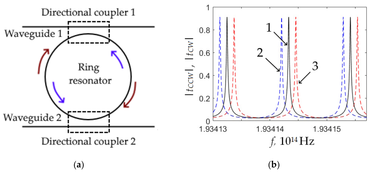
Figure 2.
(a) The dependency of the output power of the interference – 1 and filtering – 2 type gyroscopes using one ring resonator on fN; (b) Enlarged sections of graphs.
Figure 2.
(a) The dependency of the output power of the interference – 1 and filtering – 2 type gyroscopes using one ring resonator on fN; (b) Enlarged sections of graphs.
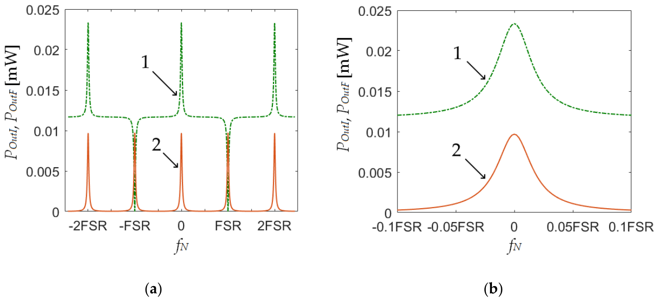
Figure 3.
Optical parallel-coupled ring resonators operating in transmission regime.
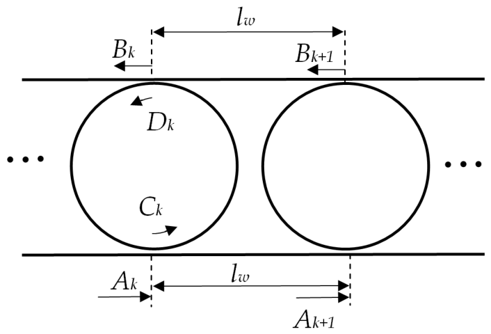
Figure 4.
Moduli of the transfer functions: (a) A single ring resonator |t1| – 1 and two parallel-coupled ring resonators |t2| – 2; (b) A single ring resonator |t1| – 1 and three parallel-coupled ring resonators |t3| – 3.
Figure 4.
Moduli of the transfer functions: (a) A single ring resonator |t1| – 1 and two parallel-coupled ring resonators |t2| – 2; (b) A single ring resonator |t1| – 1 and three parallel-coupled ring resonators |t3| – 3.
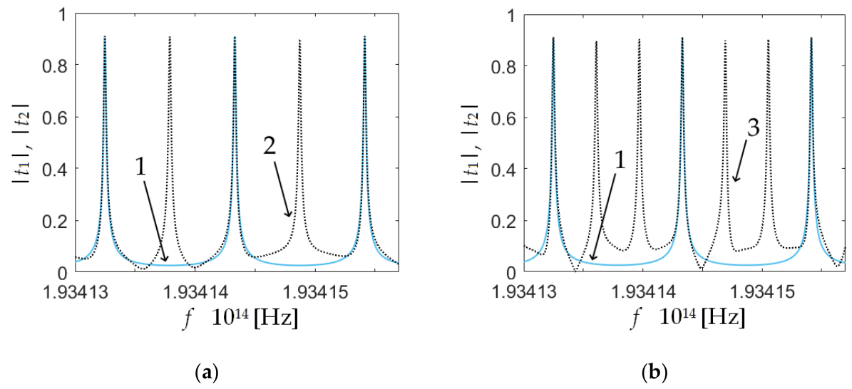
Figure 5.
The powers POutI and POutF when using one, two, three and four resonators – POutI1 and POutF1, POutI2 and POutF2, POutI3 and POutF3, POutI4 and POutF4, respectevly.
Figure 5.
The powers POutI and POutF when using one, two, three and four resonators – POutI1 and POutF1, POutI2 and POutF2, POutI3 and POutF3, POutI4 and POutF4, respectevly.
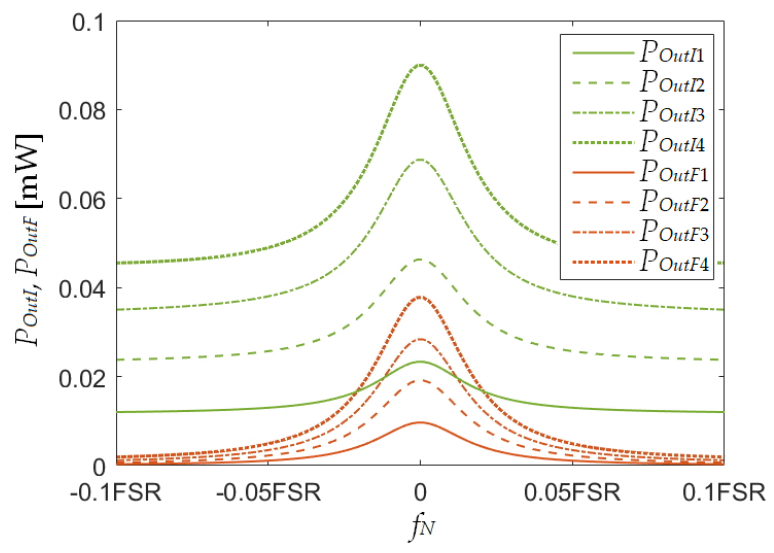
Figure 6.
The dependency of the filtering-type (red) and interference-type (green) gyroscope parameters at Κ = 0.05 (squares and circles) and Κ = 0.1 (triangles and splats) on the number of rfesonators: (a) T; (b) p1; (c) p2; (d) p3.
Figure 6.
The dependency of the filtering-type (red) and interference-type (green) gyroscope parameters at Κ = 0.05 (squares and circles) and Κ = 0.1 (triangles and splats) on the number of rfesonators: (a) T; (b) p1; (c) p2; (d) p3.
Disclaimer/Publisher’s Note: The statements, opinions and data contained in all publications are solely those of the individual author(s) and contributor(s) and not of MDPI and/or the editor(s). MDPI and/or the editor(s) disclaim responsibility for any injury to people or property resulting from any ideas, methods, instructions or products referred to in the content. |
© 2026 by the authors. Licensee MDPI, Basel, Switzerland. This article is an open access article distributed under the terms and conditions of the Creative Commons Attribution (CC BY) license (http://creativecommons.org/licenses/by/4.0/).
Copyright: This open access article is published under a Creative Commons CC BY 4.0 license, which permit the free download, distribution, and reuse, provided that the author and preprint are cited in any reuse.