
Submitted:
14 August 2026
Posted:
18 August 2026
You are already at the latest version
Abstract
To investigate the difference of shallow water delta front subfacies reservoir, Moxizhuang area, located in the central Junggar Basin, was selected. Four sedimentary microfacies combination styles, including superimposed underwater distributary channel combination, truncated underwater distributary channels combination, superimposed estuarine dam combination and upper channel and lower residual dam combination, were identified, and the typical identification marks were analyzed. The typical characteristics of reservoirs developed by different sedimentary microfacies combination styles were summarized in combination with hydrodynamic index, physical property parameters and thin sections. The results indicate that the shallow water delta front subfacies mainly develop superimposed underwater distributary channel combination, truncated underwater distributary channels combination, while the development of superimposed estuarine dam combination and upper channel and lower residual dam combination is relatively limited. Superimposed underwater distributary channel combination and superimposed estuarine dam combination are mainly formed under relatively weak hydrodynamic conditions, while truncated underwater distributary channels combination and upper channel and lower residual dam combination are mainly formed under strong hydrodynamic conditions. The reservoir developed by superimposed underwater distributary channel combination type is dominated by sandstone deposition with good sorting, developed rigid debris, weak cementation, strong dissolution, high porosity and permeability, and weak reservoir heterogeneity. It is the most favorable reservoir type of shallow water delta front subfacies.
Keywords:
sedimentary microfacies combination style
; hydrodynamic index
; microscopic characteristics
; reservoir variability
1. Introduction
The concept of shallow-water delta is first proposed by Fisk in 1954 when studying the Mississippi Delta [1] Fisk. Nowadays, Shallow-water delta sedimentation has always been a hot research topic for scholars. Most scholars believe that the water depth is an important factor controlling the development of shallow-water delta [2], which are mainly formed in environments with shallow water bodies, flat terrain, and slow construction [3]. Shallow water delta is a kind of highly constructive delta [4], and dominated by delta front subfacies [5,6], which can be subdivided into “inner front subfacies” and “outer front subfacies” [5,6]. The inner front subfacies is widely distributed, and coal seams are widely developed in the plain subfacies and inner front subfacies [5,6]. The underwater distributary channel sand is the framework sand body, with characteristics of multiple parallel branches, frequent diversion, and a strip-shaped distribution in the downstream direction [7]. In shallow water delta, the estuarine dam microfacies are relatively rare, and gravity flow sedimentation is not developed, nor is there a three-layer structure of Gilbert delta modal [8]. A shallow water delta developed in a large depression lacustrine basin, with a wide distribution of sand bodies and a characteristic of “full of sand in the basin “[9].
In recent years, scholars have begun to pay attention to the study of the combination styles of sedimentary microfacies in shallow water deltas. They used the Yanchang Formation of the Ordos Basin as an example to divide the underwater distributary channels in the shallow-water delta front into truncated distributary channels and intact distributary channels, and divided the estuarine dam into isolated and superimposed estuarine dam [10]. They also noted that the same sedimentary microfacies can have significant differences in their reservoir physical property and oil content due to different combinations [11]. Furthermore, they divided the shallow water delta front of the Fanxue area in the Ordos Basin into six combination types: truncated underwater distributary channel combination, separated underwater distributary channel combination, stacked estuarine dam combination, upper channel and lower dam combination dominated by channel, upper channel and lower dam combination dominated by dam, and upper channel and lower dam combination symmetrically [12]. They believe that the estuarine dam sand and channel-dam composition sand are important favorable reservoirs [12].
Former research has shown that the formation mechanism of sedimentary microfacies combination styles and their control over reservoir effectiveness have been widely studied, but a systematic theory has not yet been formed. Research on the sedimentary microfacies combination styles is still in its early stages.
In Junggar Basin, scholars have also established the shallow water delta sedimentary model of the Jurassic Sangonghe Formation. They believe that the shallow water delta is mainly dominated by the front subfacies, underwater distributary channels are developed, estuary dams are not developed, and the vertical sequence is different from the normal delta [13]. At the same time, four types of sedimentary microfacies combination styles were identified, including superimposed underwater distributary channel combination, superimposed underwater distributary channels combination, stacked estuarine dam combination and upper channel and lower dam combination. It is believed that under the shallow water delta sedimentary background, different sedimentary microfacies combination styles will lead to significant differences in reservoir properties and oil content [14]. In the actual exploration, significant differences of oil content and oil testing results in shallow water delta front reservoir with the same sedimentary microfacies, similar lithology, similar oil level, and similar trap conditions were discovered (Figure 1).
Therefore, this study takes the 2nd member of the Jurassic Sangonghe Formation in the Moxizhuang area in the hinterland of the the Junggar Basin as an example, based on systematic analysis of core data, starting from the genetic conditions of sand bodies, divides sedimentary microfacies combination styles, and analyzes the facies sequence characteristics and formation conditions of different sedimentary microfacies combination styles. Further analysis of the hydrodynamic index will be conducted to investigate the differences in hydrodynamic conditions among different sedimentary microfacies combination styles, supplemented by microscopic observation of cast thin sections, to clarify the microscopic differences of different sedimentary microfacies combination styles. Finally, the basic characteristics of different types of reservoir sand bodies in the shallow water delta front will be clarified, providing direction for the next step of oil and gas exploration.
2. Geological Setting
The study area is located in the Well Pen1 west sag of central Junggar Basin, with the Mosuowan uplift in the east, the Zhongguai uplift in the west, the Dabasong uplift in the north, and Shawan sag in the south, which is generally characterized by a monoclinic structure of low in the south and high in the north (Figure 2). Since the Permian, the study area has experienced the late Hercynian rifting stage, the Indosinian–Yanshanian depression stage and the Himalayan regenerative foreland basin evolution stage [15,16,17]. Among them, the Yanshanian period is mainly characterized by stable settlement and a large range of deposits were received [15,17]. The stratums are fully and continuously developed from Paleozoic to Cenozoic. The main target formation is the Jurassic Sangonghe Formation (J1s), which can be divided into lower member (J1s1), middle member (J1s2) and upper member (J1s3) from the bottom to the top. J1s1 and J1s3 formation mainly develop thick layers of gray mudstone interbedded with thin layers of fine sandstone and siltstone. The lower part of J1s2 mainly develops thick layers of gravel and sandstone, and the sediment grain size becomes finer from bottom to top [13,18].
3. Materials and Methods
The research samples used herein come from 15 coring wells in the research area. A total of 133 clastic rock samples from the target layer were collected for the laser particle size analysis measurement and the optical examinations of thin sections. All the measurements and examinations were conducted in the State Key Laboratory of Petroleum Resources and Prospecting, China University of Petroleum (Beijing). The detection instrument of the particle size analysis is Partica LA-950V2, a Japan Laser scattering particle size distribution analyzer, with a measurement range of 10~3000μm. The samples were soaked in 10% HCl for 24 h to remove the calcium cement, filtered to remove the acid, and then dried in a constant temperature oven at 60℃ for 72 h. The dried samples were put into an agate mortar for grinding to completely separate the particles. About 1 g of samples was added to the instrument for particle size analysis. Moreover, a Japanese Nikon polarizing microscope was used for the optical examinations of thin sections.
4. Results
4.1. Types and Characteristics of Sedimentary Microfacies Combination
On the basis of previous studies [14], four sedimentary microfacies combination styles were identified in the region, including superimposed underwater distributary channel combination (SC) truncated underwater distributary channels combination (TC), superimposed estuarine dam combination (SE) and upper channel and lower residual dam combination (CE). The four sedimentary microfacies combination styles have differences in lithological sequences, reservoir heterogeneity, porosity and permeability (Figure 3). Under the sedimentary background of shallow water delta front, the underwater distributary channel microfacies in the study area are very developed, and estuarine dam are only slightly developed in local areas. Therefore, superimposed underwater distributary channel combination and truncated underwater distributary channels combination are more common, while superimposed estuarine dam combination and upper channel and lower dam combination are relatively rare.
4.1.1. Superimposed Underwater Distributary Channel Combination (SC)
The SC is characterized by the vertical superposition of two or more underwater distributary channel sand bodies. The single-stage channel phase sequence is complete, and it has the positive rhythm characteristics of gradually thinning from bottom to top. The scour surface structure can be seen at the bottom, and the mudstone or carbon debris layer is common at the top, reflecting the relatively complete channel sedimentary sequence. The lithology is mainly sandy deposition and has good sorting (Figure 3a).
The overall distribution of porosity and permeability of SC reservoirs is relatively concentrated, and the heterogeneity is weak. The porosity value is 3.7~22.6%, with an average of 12.78%. The permeability value is 0.28~120×10-3μm2, with an average of 21.07×10⁻³μm2 (Figure 3a).
4.1.2. Truncated Underwater Distributary Channels Combination (TC)
The TC is characterized by the vertical superposition of two or more underwater distributary channel sand bodies. Different from the SC, the single-stage channel sequence is incomplete, showing that the late channel strongly scours the early channel, resulting in partial erosion of the early channel. A large number of retained sediments such as mud gravel, torn carbon debris or gravel are common at the bottom of the single-stage river channel, and rare mudstone or carbon debris layer are rare at the top, generally dominated by sandstone. Compared with the SC, the lithology is coarse, mainly conglomerate, pebbly sandstone and sandstone, and the sorting is poor (Figure 3b).
The overall distribution of porosity and permeability of TC reservoirs is relatively dispersed, and the heterogeneity is strong. The porosity value is 1.7~22.6%, with an average of 12.06%. The permeability value is 0.02~107×10-3μm2, with an average of 12.69×10⁻³μm2 (Figure 3b).
4.1.3. Superimposed Estuarine Dam Combination (SD)
The SE is characterized by the vertical superposition of two-stage or multi-stage estuarine dam sand bodies. The single-stage estuarine dam is characterized by the reverse rhythm of the lower fine and upper coarse. The lithology mutation interface can be seen at the top, and the carbon debris layer can be seen at the bottom. The argillaceous content increases from top to bottom, generally dominated by medium sandstone, fine sandstone and siltstone, and the sorting is good (Figure 3a).
The single-stage estuary dam has the characteristics of increasing sandstone content and decreasing argillaceous content from bottom to top, so the physical properties of the upper part are better than those of the lower part. The multi-stage superimposed estuary dams lead to uneven distribution of vertical porosity and permeability. The porosity value is 4.4~15.8%, with an average of 11.02%. The permeability value is 0.03~3.69×10⁻³μm2, with an average of 0.53×10⁻³μm2 (Figure 3c).
4.1.4. Upper Channel and Lower Residual Dam Combination (CD)
The lower part of CD is an incomplete reverse-rhythm estuary dam, and the upper part is superimposed with a positive-rhythm underwater distributary channel deposition. The superimposed interface has obvious scour surface structure. It shows that the underwater distributary channel strongly scours the early formation of the estuary dam, resulting in the early formation of the estuary dam is incomplete. The lithology of the residual estuary dam in the lower part is fine, mainly composed of fine sandstone and siltstone, with higher shale content and good sorting. The lithology of the underwater distributary channel in the upper part is coarse, mainly conglomerate, pebbly sandstone and sandstone, and a large number of mud gravel and torn carbon debris are common at the bottom, and the sorting is poor (Figure 3d).
The porosity and permeability of CD reservoir are the lowest among the four sedimentary microfacies combination styles. The porosity value is 5.4~14.4%, with an average of 9.12%. The permeability value is 0.05~4.37×10⁻³μm2, with an average of 0.36×10⁻³μm2 (Figure 3d).
4.2. Hydrodynamic Condition
In order to further explore the formation reasons of different sedimentary microfacies combination, this study explores the differences of hydrodynamic conditions between different sedimentary microfacies combination types from the perspective of sediment grain size.
Previous studies [19] have shown that the application of hydrodynamic index can quantitatively reflect the size of hydrodynamic force. In this study, the particle size of debris particles is used as a function of hydrodynamic force, and the particle size classification is carried out according to the Udden-Wentworth standard. The grades are distinguished by the power of 2. This classification increases with the increase of particle size, and conforms to the relationship between the external force of debris and the water flow velocity in the Hjulstrms diagram, so as to analyze the hydrodynamic law between the four sedimentary microfacies combination types.
The hydrodynamic index at point i is defined as:
In the formula:
- pij—The proportion of the jth lithology at point i in the target section;
- dj—The hydrodynamic strength represented by the jth lithology;
- m—The total number of clastic rock lithology categories;
- n—Total number of sample points;
The hydrodynamic indices of 133 samples were calculated to analyze the hydrodynamic conditions of different sedimentary microfacies combination types. The hydrodynamic index of SC is 10.08~15.41, with an average of 13.01; the hydrodynamic index of TC is 15.52~26.06, with an average of 20.43; the hydrodynamic index of SD is 10.40~11.78, with an average of 10.92; the hydrodynamic index of CD is 13.44~19.93, with an average of 16.12. The calculation results indicate that the hydrodynamic environment for TC development is the strongest, followed by CD and SC, while the hydrodynamic environment for SD development is the weakest.
4.3. Microscopic Characteristics
The thin sections are used to observe the microscopic characteristics of different sedimentary microfacies combination styles and explore the development law of diagenesis and its impact on the heterogeneity of reservoir.
4.3.1. Rock Fabric Characteristics
The types of sedimentary microfacies formed under different hydrodynamic conditions and sedimentary environments have a controlling effect on reservoir properties. The rock fabric characteristics of the reservoir in the research area mainly include particle size, sorting and roundness, rock debris composition, impurity content, etc. Among them, the differences in rock debris type and content have the greatest impact on the reservoir.
The rocks of the J1s2 formation in the study area are mainly composed of quartz and feldspar, but generally have a high content of rock debris. Rocks with different sedimentary microfacies combination styles exhibit significant differences in sorting, roundness, pore type, particle contact relationship, and rock debris type and content.
The rock developed by SC has good sorting, most of the particles are sub-angular and sub-circular, and the content of intergranular pores are relatively high (Figure 4a), mainly point-line contact (Figure 4e). The types of rock debris are mainly rigid debris such as flint and metamorphic quartzite (Figure 4a,c). Brittle deformation such as fracture often occurs during extrusion, which has little effect on reservoir space and less matrix content.
The rock developed by TC has poor sorting, the particles are mainly sub-angular and angular (Figure 4b), the content of intergranular pores is low, and the particles are mostly linear contact and concave-convex contact. The types of debris are mainly plastic debris such as tuff, phyllite and schist, which enhances the density of the reservoir to a certain extent.
The rock developed by SD has good sorting, most of the particles are sub-circular, the whole is dense, and the particles are mostly in line contact (Figure 4d). The debris types are mainly plastic debris such as phyllite and schist, with low acrobatics content and high structural maturity.
The rocks developed by CD have the common characteristics of TC and SD. The rocks developed by the upper channel sediments have poor sorting, and the particles are mainly sub-angular and angular. The rocks developed by the lower estuary dam sediments have good sorting, and the particles are mostly sub-circular. The debris types are mainly tuff, phyllite, schist and other plastic debris, and the reservoir is dense.
4.3.2. Diagenetic Characteristics
Diagenesis directly controls the pore evolution and is a key factor in the formation of effective reservoirs. The main diagenesis in the study area includes compaction, cementation and dissolution. The compaction effect is affected by the buried depth and increases with the buried depth. The influence of cementation is the most critical. The common cements in the study area are iron calcite, iron dolomite and anhydrite. The development degree of dissolution is related to the content of plastic debris and cement. Generally, the dissolution of sandstone with low plastic debris content, coarse grain size and low cement content is more developed.
This study shows that the main diagenesis in different sedimentary microfacies combination styles is different, but it also has certain regularity.
Because of a large number of rigid cuttings in the rocks of SC, the particles are often accompanied by rotation, dislocation, crushing and other phenomena during the compaction process, and a large number of primary pores are preserved after compaction (Figure 4e). It is mainly early ferrocalcite cementation (Figure 4c) and late sparry calcite cementation, which is conducive to the later fluid to transform it. The dissolution is more developed, the secondary pores account for a large proportion, and it is easy to form favorable reservoirs.
The rocks of TC contains a large number of plastic debris, mainly cementation, more common ferrocalcite basal cementation (Figure 4f), later fluid is difficult to transform it, quartz overgrowth is also more common, dissolution is weak, resulting in more dense reservoirs (Figure 4i).
The content of the plastic debris of SD rocks is high, and the compaction is strong. The anhydrite crystal cementation is common and distributed in layers (Figure 4g). The dissolution is weak, resulting in reservoir densification.
The content of the plastic debris of CD rocks is high, and the compaction is strong. The crystal cementation of calcite dense cementation and ankerite is common. The dissolution is not developed, and the reservoir physical properties are poor (Figure 4h).
5. Discussion
This study found that there are four types of sedimentary microfacies combination styles developed in the front edge of shallow water delta, forming four types of reservoirs. Due to the different backgrounds of different sedimentary microfacies combination styles, there are certain differences in the physical and heterogeneous characteristics of the formed reservoirs.
5.1. Formation Background
The SC style mainly exhibits weak hydrodynamic environment characteristics and is a product of lateral migration of underwater distributary channels. It generally develops in the outer front subfacies and the inner front subfacies edges of shallow water deltas. This style was formed during the period of rising base-level, with an increased relatively accommodative space. Therefore, the downward cutting effect of the channel is not obvious, and the single phase channel sequence is relatively complete. The lithology is relatively fine and generally dominated by sandstone.
The hydrodynamic conditions for the TC style are the strongest, commonly found in the outer front subfacies edge of shallow water deltas. During periods of little or gradual decline in the base-level, there is insufficient of relatively accommodating space. The channel formed in the early stage is eroded by the late river channel, which leads to the erosion of the early channel. The sequence of single stage channels is incomplete, exhibiting the characteristics of incomplete positive rhythmic superposition. The lithology is relatively coarse, mainly composed of conglomerate and sandstone.
The hydrodynamic condition of the SC style is the weakest, which is common in the outer front subfacies of the shallow water delta. This type formed at the end of the extension of the underwater distributary channel to the basin. Due to the rise of the base-level, the relative accommodation space increases, and the hydrodynamic effect of the lake is strong, forming a multi-stage vertical superimposed complete estuary dam. The sand body is well sorted, and the lithology is relatively fine, mainly sandstone.
The hydrodynamic condition of the CD style is strong, which is common in the outer front subfacies of the shallow water delta. Due to the decline of the base-level and the relative lack of accommodation space, the early formed estuary dam is eroded by the late channel, leaving only the middle and lower part of the original estuary dam, which is the result of the advance of the underwater distributary channel. The lithology changes greatly. The upper part of the underwater distributary channel sand body is coarse, mostly pebbly sandstone and sandstone, and the lower part of the residual mouth bar sand body is fine, mostly sandstone.
5.2. Reservoir Properties and Heterogeneity
The four sedimentary microfacies combination styles not only have great differences in lithology sequence, but also have great differences in reservoir porosity, permeability and heterogeneity.
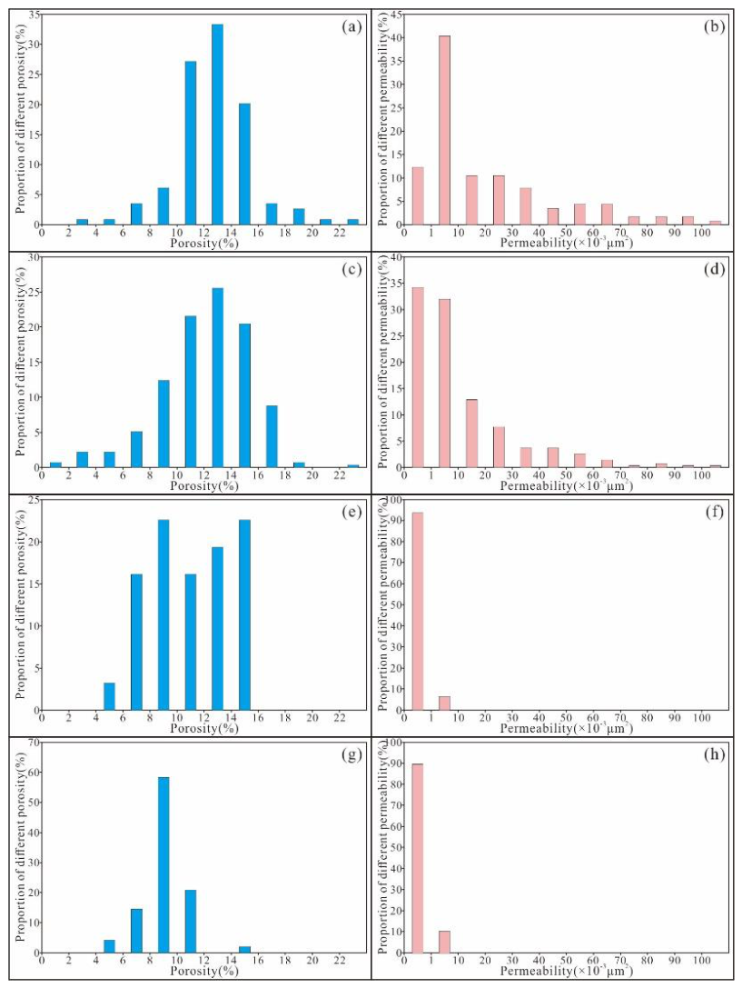
The reservoirs of SC-style have higher porosity and permeability values. The porosity of 33.33% samples is 12~14%, and the main porosity distribution interval is 10~16%. The permeability of 40.35% samples is 1~10×10-3μm2. The distribution of porosity and permeability values is relatively concentrated, and the reservoir heterogeneity is weak (Figure 5a,b).
The reservoirs TC-style also have higher porosity and permeability values. The porosity of 25.55% samples is 12~14% and the main porosity distribution interval is 8-18%. The permeability of 34.19% samples is 1~10×10-3μm2, and the main permeability distribution interval is 0~10%×10-3μm2. The distribution of porosity and permeability is more dispersed, and the reservoir heterogeneity is the strongest (Figure 5c,d).
The reservoirs of SD-style have medium porosity values and low permeability values. The porosity of 22.58% samples is 8~10% and the main porosity distribution interval is 6~16%. The permeability of 93.55% samples is 0~1×10⁻³μm2. The porosity distribution is dispersed and the reservoir heterogeneity is strong (Figure 5e,f).
The reservoir porosity and permeability values of the CD style are low. The porosity of 58.33% samples is 8~10% and the main porosity distribution interval is 6~12%. The permeability of 89.58% samples is 0~1×10⁻³μm2. The distribution of porosity and permeability is relatively concentrated, and the reservoir heterogeneity is weak, but the reservoir physical properties are the worst (Figure 5g,h).
5.3. Reservoir Space and Favorable Reservoirs
The reservoir of SC style has good sorting, mainly rigid debris and low matrix content. In the compaction process, the primary pores can be well preserved. The dissolution is strong and the secondary pores are well developed, which conduct the higher porosity and permeability values. The reservoir heterogeneity is weak. It is the most favorable reservoir type in the study area.
The reservoir of TC style has poor sorting, mainly plastic debris and high matrix content. The primary pores cannot be well preserved during the compaction process. The cementation is strong and the dissolution is weak. Although it has high porosity and permeability values, the reservoir heterogeneity is strong and it is a non-favorable reservoir.
The reservoir of SD style has good sorting and is dominated by plastic debris. During the compaction process, the primary pores cannot be well preserved. The cementation is strong and the dissolution is weak. It has a medium porosity value and a low permeability value and the reservoir heterogeneity is strong. It is difficult to form a favorable reservoir.
The reservoir of CD style is dominated by plastic debris, with strong compaction and cementation, weak dissolution, low porosity and permeability values, and belongs to non-favorable reservoir.
6. Conclusions
The reservoir of SC style has good sorting, mainly rigid debris and low matrix content. In the compaction process, the primary pores can be well preserved. The dissolution is strong and the secondary pores are well developed, which conduct the higher porosity and permeability values. The reservoir heterogeneity is weak. It is the most favorable reservoir type in the study area.
The reservoir of TC style has poor sorting, mainly plastic debris and high matrix content. The primary pores cannot be well preserved during the compaction process. The cementation is strong and the dissolution is weak. Although it has high porosity and permeability values, the reservoir heterogeneity is strong and it is a non-favorable reservoir.
The reservoir of SD style has good sorting and is dominated by plastic debris. During the compaction process, the primary pores cannot be well preserved. The cementation is strong and the dissolution is weak. It has a medium porosity value and a low permeability value and the reservoir heterogeneity is strong. It is difficult to form a favorable reservoir.
The reservoir of CD style is dominated by plastic debris, with strong compaction and cementation, weak dissolution, low porosity and permeability values, and belongs to non-favorable reservoir.
Author Contributions
Conceptualization, T.X. and C.C.; methodology, C.C.; validation, Y.Z., H.L.; formal analysis, Y.Z.; investigation, C.C.; resources, Z.Z. and K.Z.; data curation, H.C.; writing—original draft preparation, C.C.; writing—review and editing, T.X.; visualization, Q.Q.; supervision, T.X.; project administration, K.Z.; funding acquisition, K.Z. and Z.Z..
Funding
This research was funded by Xinjiang Uygur Autonomous Region Key R&D Special Project, grant number 2024B01015-3.
Conflicts of Interest
The authors declare no conflicts of interest.
Abbreviations
The following abbreviations are used in this manuscript:
| SC | Multidisciplinary Digital Publishing Institute |
| TC | Truncated underwater distributary channels combination |
| SD | Superimposed estuarine dam combination |
| CD | Upper channel and lower residual dam combination |
References
- Fisk, H. N. Sedimentary fremwork of the Modern Mississippi Delta. J. Sediment. Petrol. 1954, 24, 76–99. [Google Scholar] [CrossRef]
- Donaldson, A. C. Pennsylvanian sedimentation of Central Appalachians. In Geological society of america special papers; 1974. [Google Scholar] [CrossRef]
- POSTMA, G. An analysis of the variation in delta architecture. Terra Nova 1990, 2, 124–130. [Google Scholar] [CrossRef]
- Li, Y.; Ding, X.; Wang, X. Z.; Li, Y. H.; Yu, H. H. Structural characteristics of sand bodies in shallow-water deltas in the Chang 8 Member of Yanchang Formation, Ordos Basin. Nat. Gas. Geosci. 2021, 32, 57–72. [Google Scholar]
- Li, Y. H.; Liu, C. Y.; Du, Y. G.; Wang, X. J.; Huang, J. X. Sedimentary characteristics of shallow water delta and lake shoreline control on sandbodies of Chang 8 oil-bearing interval of the Upper Triassic Yanchang Formation in northwestern OrdosBasin. J. Palaeogeogr. 2009, 11, 266–274. [Google Scholar]
- Liu, H. Q.; Li, X. B.; Wanyan, R.; Wei, L. H.; Liao, J. B. Palaeogeographic and sedimentological characteristics of the Triassic Chang 8, Ordos Basin, China. Acta Sedimentol. Sin. 2011, 29, 1086–1095. [Google Scholar]
- Zhu, W. L.; Li, J. P.; Zhou, X. H.; Guo, Y. H. Neogene shallow water deltaic system and large hydrocarbon accumulations in BohaiBay, China. Acta Sedimentol. Sin. 2008, 26, 575–582. [Google Scholar]
- Lou, Z. H.; Lan, X.; Lu, Q. M.; Cai, X. Y. Control of the topography, climate and lake level fluctuation on the depositional environment on a shallow-water delta: A Case Study of the Ceataceous Putaohua Reservoir in the Northern Part of Songliao Basin. Acta Geol. Sin. 1999, 73, 83–92. [Google Scholar]
- Zhu, X. M.; Liu, Y.; Fang, Q.; Li, Y.; Liu, Y. Y.; Wang, R.; Song, J.; Liu, S. Q.; Cao, H. T.; Liu, X. N. Formation and sedimentary model of shallow delta in large-scale lake: Example from Cretaceous Quantou Formation in Sanzhao Sag, Songliao Basin. Earth Sci. Front. 2012, 19, 89–99. [Google Scholar]
- Li, F. J.; Wang, D. Y. The microfacies architecture and zoning of delta front in depressed-type lacustrine basin: taking the Yanchang Formation of Triassic in Ordos basin as an example. Nat. Gas. Geosci. 2006, 17, 775–777. [Google Scholar]
- Zhang, M. L.; Li, X. Z.; Gu, J. R.; Xie, W. R. Division and evaluation of sand body assemblages: An example from Shan 2 and He 8 member of Upper Paleozoic in Ordos Basin. Lithol. Reserv. 2009, 21, 12–18. [Google Scholar]
- Zhang, R.; Ren, L. Y.; He, Y. H.; Ma, F. X.; Meng, W. C.; Zhang, H. M.; Chen, Y. G.; Bai, X. Y. Characteristics and oil and gas significance of sedimentary microfacies combinations in the delta front of Fanxue area in Ordos Basin. J. Yanan Univ. (Natural Science Edition) 2015, 34, 24–27. [Google Scholar]
- Zheng, S. Sedimentary pattern of the shallow-water delta in the Sangonghe Formation of Central Junggar Basin and its significance for hydrocarbon exploration. Spec. Oil Gas. Reserv. 2019, 26, 87–93. [Google Scholar]
- Liu, Z. Q. Controlling elements and evaluation model of the Jurassic hydrocarbon accumulation in central Junggar basin. J. Henan Polytech. Univ. (Natural Science) 2019, 38, 42–50. [Google Scholar]
- Sun, J.; Xue, J. J.; Hou, F. G.; Wu, A. C.; Song, M. X.; Zhu, F. Sedimentary characteristics and model of sandy debris current in depression area of lacustrine basin: A case study of the Jurassic Sangonghe formation in the western well Pen-1 sag, Junggar basin. J. China Univ. Min. Technol. 2019, 48, 858–869. [Google Scholar]
- Lu, B.; Zhang, J.; Li, T.; Lu, M.A. Analysis of tectonic framework in Junggar basin. Xinjiang Pet. Geol. 2008, 29, 283–289. [Google Scholar]
- Guo, Q. Z.; Tan, J. M.; Li, D. Q.; Lan, H.; Qiu, P.; Xu, T.; Sun, T.; Yin, W. Grain size curve characteristics of 2nd Member of Sangonghe Formation in Qianshao Area and its indicative significance of hydrodynamic environment. Appl. Sci. 2022, 12, 9852. [Google Scholar] [CrossRef]
- Zhang, J. H. Characteristics of low-permeability reservoir of Sangonghe Formation in Block 1 of central Junggar Basin. Complex Hydrocarb. Reserv. 2018, 11, 17–22. [Google Scholar]
- Zou, Y. R.; Cai, Y. L. Hydrodynamic index method and its application to depositional environment. J. China Coal Soc. 1997, 22, 113–116. [Google Scholar]
Figure 1.
Characteristics and oil testing results of different types of reservoirs in the shallow delta front of the research area. (a) Well ZH1, 4811.2m, Oil soaked fine sandstone, 10t oil per day and without water; (b) Well ZH11, 4416.9m, Oil spot fine sandstone, 0.42t oil and 27.7m3 water per day; (c) Well S1, 3664.5m, Oil spot fine sandstone, 81.9m3 water per day.
Figure 1.
Characteristics and oil testing results of different types of reservoirs in the shallow delta front of the research area. (a) Well ZH1, 4811.2m, Oil soaked fine sandstone, 10t oil per day and without water; (b) Well ZH11, 4416.9m, Oil spot fine sandstone, 0.42t oil and 27.7m3 water per day; (c) Well S1, 3664.5m, Oil spot fine sandstone, 81.9m3 water per day.
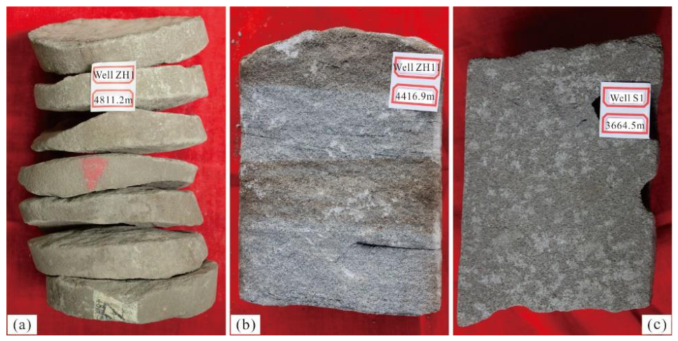
Figure 2.
Tectonic location and lithological column of the Moxizhuang area. (a) Tectonic location of the research area in Jungger Basin; (b) Structural well location map of the study area; (c) Lthologic histogram of the Sangonghe formation.
Figure 2.
Tectonic location and lithological column of the Moxizhuang area. (a) Tectonic location of the research area in Jungger Basin; (b) Structural well location map of the study area; (c) Lthologic histogram of the Sangonghe formation.
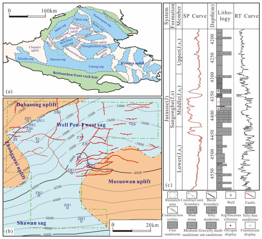
Figure 3.
The histogram of different sedimentary microfacies combination types. (a) SC type, Well ZH1; (b) TC type, Well S1; (c) SD type, Well Z102; (d) CD type, Well S1.
Figure 3.
The histogram of different sedimentary microfacies combination types. (a) SC type, Well ZH1; (b) TC type, Well S1; (c) SD type, Well Z102; (d) CD type, Well S1.
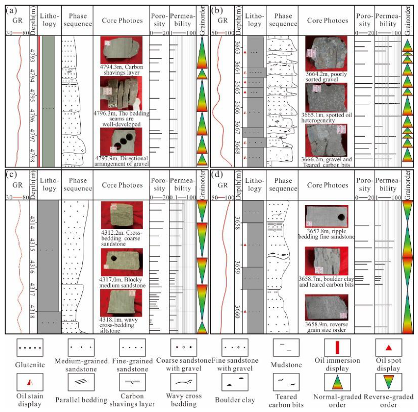
Figure 4.
The microscopic characteristics of different sedimentary microfacies combination styles. (a) Well S1, 3662.15m, single polarized light, SC type, high quartz content, low plastic debris content, pore cementation; (b) Well S1, 3670.80m, single polarized light, TC type, basal cementation; (c) Well S2, 3432.70m, SC type, calcite is pore cementation, metamorphic quartz and other rigid chips, dissolution strength is weak; (d) Well Z102, 4317.00m, orthogonal light, SD type, phyllite, tuff, schist and other soft rock debris and rigid particles are linear and concave convex contact, partial pseudo-hybridization; (e) Well S1, 3679.00m, single polarized light, SC type, rigid particles are mostly point contact, a small amount of line contact, rigid feldspar particles are broken; (f) Well S1, 3680.00m, orthogonal light, TC type, early calcite is connected crystal basal cementation, particles are ‘suspension’ shape; (g) Well ZH1, 4785.68m, orthogonal light, SD type, dense cementation of anhydrite in relatively coarse part; (h) Well S1, 3657.80m, orthogonal light, CD type, embedded crystal cemented dolomite is completely occupied by carbon asphalt dissolved pore; (i) Well S1, 3670.80m, orthorhombic light, TC type, quartz increased edge to make the rock more dense.
Figure 4.
The microscopic characteristics of different sedimentary microfacies combination styles. (a) Well S1, 3662.15m, single polarized light, SC type, high quartz content, low plastic debris content, pore cementation; (b) Well S1, 3670.80m, single polarized light, TC type, basal cementation; (c) Well S2, 3432.70m, SC type, calcite is pore cementation, metamorphic quartz and other rigid chips, dissolution strength is weak; (d) Well Z102, 4317.00m, orthogonal light, SD type, phyllite, tuff, schist and other soft rock debris and rigid particles are linear and concave convex contact, partial pseudo-hybridization; (e) Well S1, 3679.00m, single polarized light, SC type, rigid particles are mostly point contact, a small amount of line contact, rigid feldspar particles are broken; (f) Well S1, 3680.00m, orthogonal light, TC type, early calcite is connected crystal basal cementation, particles are ‘suspension’ shape; (g) Well ZH1, 4785.68m, orthogonal light, SD type, dense cementation of anhydrite in relatively coarse part; (h) Well S1, 3657.80m, orthogonal light, CD type, embedded crystal cemented dolomite is completely occupied by carbon asphalt dissolved pore; (i) Well S1, 3670.80m, orthorhombic light, TC type, quartz increased edge to make the rock more dense.
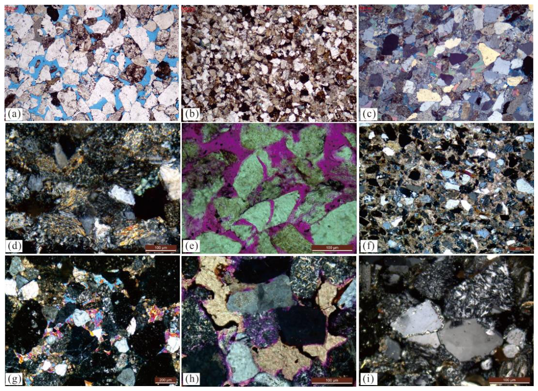
Figure 5.
The porosity and permeability distribution of different sedimentary microfacies combination types. (a) The porosity of SC type; (b) The permeability of SC type; (c) The porosity of TC type; (d) The permeability of TC type; (e) The porosity of SD type; (f) The permeability of SD type; (g) The porosity of CD type; (h) The permeability of CD type.
Figure 5.
The porosity and permeability distribution of different sedimentary microfacies combination types. (a) The porosity of SC type; (b) The permeability of SC type; (c) The porosity of TC type; (d) The permeability of TC type; (e) The porosity of SD type; (f) The permeability of SD type; (g) The porosity of CD type; (h) The permeability of CD type.
Disclaimer/Publisher’s Note: The statements, opinions and data contained in all publications are solely those of the individual author(s) and contributor(s) and not of MDPI and/or the editor(s). MDPI and/or the editor(s) disclaim responsibility for any injury to people or property resulting from any ideas, methods, instructions or products referred to in the content. |
© 2026 by the authors. Licensee MDPI, Basel, Switzerland. This article is an open access article distributed under the terms and conditions of the Creative Commons Attribution (CC BY) license (http://creativecommons.org/licenses/by/4.0/).
Copyright: This open access article is published under a Creative Commons CC BY 4.0 license, which permit the free download, distribution, and reuse, provided that the author and preprint are cited in any reuse.