

Submitted:
13 August 2026
Posted:
17 August 2026
You are already at the latest version
Abstract
Sodium-ion batteries are generally considered a promising alternative to lithium-ion batteries due to the abundance and low cost of sodium. However, their main limitation is the lack of an appropriate anode, since the usual graphite electrode used in lithium batteries is
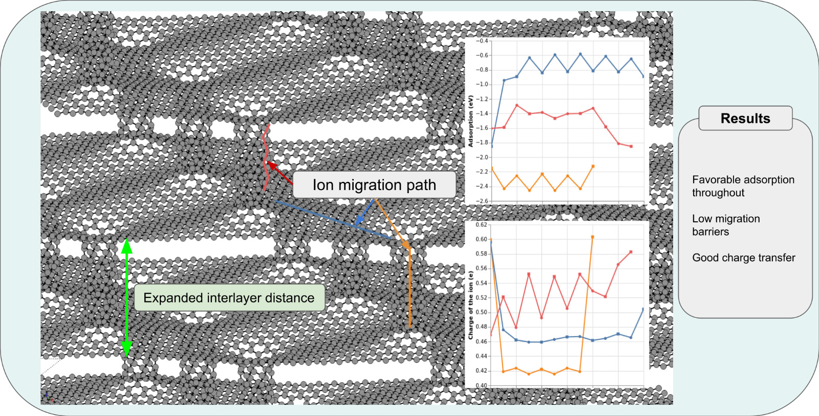
incompatible with the larger ionic radius of sodium. In this work, the theoretical behavior of pillared graphene as a possible anode is analyzed via computational simulations based on Density Functional Theory (DFT), using the FIREBALL program. The structural relaxation results reveal that staggered pillars are more stable than the aligned alternative. The adsorption energy of sodium is shown to be significantly higher than for graphite, with a maximum value of −2.23 eV, leading to an important energetic benefit. The diffusion analysis shows an exceptional mobility of sodium, with migration barriers comparable to lithium ions both in the flat regions of the structure and close to the nanotubes. The values are appreciably lower than in the standard graphite used in current batteries. Finally, the charge analysis confirms a significant electronic transfer from both sodium and lithium to the lattice. These data indicate that pillared graphene can be a good candidate for the optimization of charge dynamics in sodium-ion batteries.
Keywords:
pillared graphene
; DFT
; charge transfer
; Na-batteries
; energy barrier
1. Introduction
The global energy storage market is dominated almost entirely by lithium-ion batteries which rely on the reversible intercalation of lithium cations between a cathode and an anode. Despite their high energy density, lithium-ion batteries face a series of sustainability and supply chain constraints. The primary issue is the scarcity of lithium; there is a limited number of deposits, located in geopolitically complex areas [1], mainly in South American countries such as Chile, Bolivia, and Argentina, collectively known as the lithium triangle. Its production is also restricted to a few countries [2], predominantly China. Furthermore, mineral extraction is expensive both economically [3] and environmentally [4], as it consumes massive volumes of water and generates toxic pollutants. The use of batteries itself can be hazardous, given their tendency to combust under certain conditions due to thermal runaway [5]. Adding to this, their recycling is complex and is not practiced on a large scale [6]. Finally, lithium is not the only problematic element in these batteries, since one of the most common cathodes is made of , and cobalt is even more scarce than lithium [7]. All these factors complicate the production of these kinds of batteries.
Sodium-ion batteries offer a promising alternative due to the abundance of sodium in seawater and halite ores, alongside its favorable charge transport properties [8]. Moreover, sodium batteries do not require cobalt cathodes [9], mitigating supply chain vulnerabilities and reducing projected production costs [10].
However, a major bottleneck in the development of sodium-ion batteries is the lack of suitable anode materials. While graphite serves as an efficient host for lithium, sodium intercalation into graphite has been shown to be thermodynamically unstable [11], due to insufficient interlayer spacing. Previous theoretical simulations based on Density Functional Theory (DFT) have studied the adsorption and mobility of Na atoms intercalated in graphite, giving an explanation of the reason for the incompatibility [11,12]. Therefore, designing low-cost structurally optimized anodes capable of efficient sodium storage is necessary.
Carbon nanomaterials are ideal candidates for this purpose due to their abundance, high electrical conductivity, low weight and structural tunability. The main contender as a promising electrode for future Na-ion batteries is currently hard carbon [13,14,15,16], which despite showing promising results still has a lot of room for improvement [17]. An alternative option is expanded graphite, in which interlayer spacing is increased using functional groups [18,19]. The experimental results demonstrated that it can yield a much higher capacity than standard graphite and retain it over many charge and discharge cycles. Unfortunately, the functional groups repel the Na ions, reducing the storage density. Further works have analyzed the expanded graphite using alternative methods [20,21]. Furthermore, other theoretical works have studied the most favorable interlayer distance for the Na intercalation [22].
Following this idea, recent works have explored the possibility of expanding the graphene-graphene interlayer distance using carbon nanotubes (CNTs). Such structures, termed pillared graphene, have been primarily investigated in the context of hydrogen storage [23,24,25], but the idea can be easily extended and applied to anodes built with graphite-like materials where the increased interlayer distance could allow for greater Na mobility. Due to the difficulties of creating such a structure, it is prudent to perform theoretical simulations to test the viability of the structure for a future application as an anode in a Na-ion battery. Anyway, motivated by the initial theoretical works, some efforts have been done to build the pillared graphene experimentally [26].
In this work, we investigate, using DFT simulations, the adsorption energy and the mobility of a single Na atom within a purely carbon construction utilizing the CNTs as structural pillars to expand the interlayer distance in a graphite-like structure and maintaining the CNT bonded to both adjacent graphene sheets. CNTs were chosen for their affinity with sodium [27] and their large number of geometric degrees of freedom, allowing for tuning of height, chirality and diameter. We analyzed the stability of aligned and staggered structures, studied the adsorption energy at various points throughout the structure to determine migration barriers, and finally, we evaluated the charge transfer between the Na and the C-structure. Throughout this process, the results for Na were compared with a lithium atom in the same structure, and both Na and Li in a regular graphite structure. The results present the material as a promising structure for a future anode in a Na-ion battery.
2. Materials and Methods
A very efficient DFT localised-orbital molecular-dynamics technique (FIREBALL [28]) was used for the structural relaxation of all systems involved in this study. The computational scheme has been described in full detail elsewhere [28,29,30], therefore, only the main points are summarised here. The code is based on a self-consistent version of the Harris-Foulkes functional [31,32]. The FIREBALL simulation package uses a localized atomic orbital-like basis [33] that goes to zero for a certain cutoff radius, drastically reducing the number of interactions to be computed during the relaxation process. In the present work, the cutoff radii for the wavefunctions’ radial part defining the optimized basis set are the following: for the Na atom, for the C atom, and for the Li atom. Different C-based compounds (graphene graphite and CNT) were successfully characterized both electronically and structurally previously using this code [34,35,36]. In particular, in the graphene case, the C-C distance was , which is very similar to the experimental value of [37]. Furthermore, the density of states accurately describes the expected behavior of graphene as presented in [34]. On the other hand, the cutoff radius chosen for Na atoms has been used satisfactorily to reproduce its ionic behavior in previous works like [38]. Finally, as lithium presents a shorter ionic radius than sodium, due to their size difference, we have selected a shorter cutoff radius accordingly. In addition, the code uses the local density approximation (LDA) exchange-correlation functional calculated with the multi-centre weighted exchange correlation density approximation (McWEDA) [30] and the self-consistency is achieved via the occupation numbers given by the Harris functional [31].
As mentioned in the introduction, we analyze a carbon-based structure consisting of a graphene sheet joined to a carbon nanotube, which is acting as a structural support to increase the interlayer spacing. In our calculation, we include a periodicity in the Z-direction to reproduce a graphite-like configuration. It is important to mention that the model will present a hole in the graphene sheet in the area where the CNT is bonded. To determine the type of nanotube, the size of the graphene sheet and their relative orientation we used the results obtained by Yang et al. [39], where a (6,0) zig-zag nanotube joined to a 10x10 armchair graphene sheet (which will henceforth be called ARM-60) was found as the best option. In figure 1(a) the structure of the CNT bonded to a graphene sheet is shown. The lines represent the unit cell, meaning that the CNT of the consecutive unit cell in the Z-direction is aligned with the one presented in the figure. On the other hand, the 1(b) shows a tilted unit cell that leads to a configuration with staggered CNTs. Finally, figure 1(c) reflects the junction between the graphene layer and the CNT (see the heptagon formed due to the bonding of the C atoms coming from both the graphene and CNT). This structure was previously proposed as the best candidate for electrical conductivity [39]. Due to the large size of the system proposed, the calculations have been performed using only the Gamma point in the first Brillouin zone. The atomic relaxation was considered converged when the maximum force on any atom was less than and the maximum total energy change was smaller than .
We want to find the optimal configuration after joining the CNT to the graphite-like structure. The first important point is the study of the alignment of the nanotubes (the aligned and staggered structures can be seen in Figure 1a,b). The separation between the nanotube and graphene is an important point in our analysis. We studied the stability of the structures by slowly increasing the separation for both aligned and staggered structures until a minium is found (Section 3.1). The size of the nanotubes will also be analyzed by changing the length to determine which is optimal. Once we have found the best pillared graphene structure, one sodium or lithium atom is placed in various positions in the structure (Section 3.2). After the relaxation of these structures, we will determine the adsorption and migration barriers for both ions, as well as the charge transfer in all the calculated positions (Section 3.3). The adsorption energy () is estimated comparing the energy of the system with both Na (Li) atom in the pillared graphene structure together () and the energy of both subsystems far apart, i.e. the energy of the pillared graphene () separated to the Na (Li) atom. This last energy is calculated as the atomic energy in its corresponding bulk structure ().
A negative value means that the adsorption is favorable and a positive value implies a repulsive interaction. All these values are compared with our own simulations of the ions in a graphite structure. In particular, the reference graphite calculations consist of a 6x6 graphene unit cell, with the ion placed in the center in both a hollow and bridge position. The graphite calculation uses an interlayer distance of 3.40 Å, the value that minimizes the energy in FIREBALL. The comparison is also established with previous theoretical data when appropriate [12].
3. Results
3.1. Structural Relaxation
We have to find, as a first step, the most stable structure where the Na and Li atoms can later be placed. The initial configuration has the nanotube (of 11.36 Å in axial length) in close contact to the graphene layer (1.42 Å like the bond distance in graphene) fixing a periodicity in the Z-direction that includes the very same distance between the upper atoms of the CNT and the repeated graphene layer. Then, we increase the separation by enlarging the corresponding lattice vector. After relaxation, the C-atoms next to the hole in the grapehene sheet have been moved to create bonds with the unsaturated orbitals of the border atoms of the CNT. Repeating this process several times, we will find not only the most stable configuration but also a general trend of the behavior of the structure under a mechanical deformation. This sequential calculations will be performed for both aligned and staggered configurations shown in Figure 1a,b.
Furthermore, in the following section, we will also vary the length of the nanotube. Consequently, separation shall be defined as the difference between the periodicity in the Z axis and the length of the nanotube divided by two (given that there are two junctions), which is independent of the axial length of the nanotube.
3.1.1. Alignment
First, we will determine which of the aligned or staggered nanotubes is most stable as well as the optimal separation between the nanotube and graphene layer. Figure 2 shows the energy of both structures as a function of the separation defined before. As can be observed, the staggered structure is more stable, with its most stable configuration at 3.7 Å of separation. This apparently large distance can be understood taking a look to the atomic configuration shown in Figure 3b. Due to its great elasticity, the graphene layer presents a buckling in the original planar structure. The C atoms bonded to the CNT move up (or down depending on the position of the CNT above or bellow of the hole) around 2.25 Å. Adding the original distance of 1.42 Å between the CNT and the CNT, we have almost the distance defined. It is important to mention that while the graphene layer is strongly deformed, the CNT is only stretched by around 0.1 Å, completing the total 3.7 Å of Figure 1b. This situation leads to a large graphene-graphene distance of 18.7 Å that will allow the Na intercalation.
It is also important to notice that the aligned structure tends to "break" (the broken structure can be seen in Figure 3a) when it is stretched too far, this explains the sudden energy jump at the end of the graph. This behavior is consistent with the results of [39], since the stability of the ARM-60 structure is due to the relatively stable heptagon formed in the junction (as shown in Figure 1c). The aligned case implies bonding formation of each graphene sheet with two nanotubes (above and below), then it cannot form these very stable bonds with at least one of the sides. As a consequence, the system tends to favor the formation of said bonds with only one of the two nanotubes over maintaining symmetry at higher separations. On the contrary, the staggered structure (which can freely form these very stable bonds at both junctions) suffers a very little energetic variation as the separation increases, indicating a great resistance to mechanical deformations. This can be a favorable point for its use as an electrode working under different stress conditions.
Given the fact that the staggered structure is the more stable option, all analysis hereon will be done with the staggered configuration.
3.1.2. Nanotube Length
The length of the nanotube is an important parameter for a future electrode in Na-ion batteries as it is useful to expand the interlayer distance, favoring Na adsorption and mobility, but a large CNT can reduce the number of Na atoms accepted in the anode, reducing the electrical capacity. For this reason, it is important to study the variation with the CNT length, trying to find the most convenient configuration. Due to the type of CNT selected, the length is constrained by the fact that it must have a zig-zag edge on both ends, since this is required for the formation of the desired junction. This means that the length may vary only in increments of three atoms, meaning that length 1 will correspond to 4 atoms (2.84 Å), 2 to 7 (7.1 Å) and 3 to 10 (11.36 Å), where the original version shown in Figure 1b corresponds to length 3.
Figure 4 shows the energetic evolution (energy per C-atom) of the ARM60 staggered structure for three CNT lengths as a function of the separation defined before. The graph shows that the most stable structure is the one with the shortest nanotube, though the energy difference is relatively small compared to that obtained with the aligned case (see Figure 2). This result can be understood by the fact that the shorter the nanotube, the closer the structure to graphite, which should be the most stable option.
It is also clear that the optimal separation for all nanotubes is roughly the same, around 3.7 Å. This behavior is also expected, since the optimal separation is primarily influenced by the interaction between the graphene and nanotube (i.e. the junction), which the length of the nanotube has no bearing on.
3.2. Ion Adsorption and Migration
Once the best structure is determined, it is now possible to analyze the adsorption of the Na (Li) atom in different positions in the structure. In particular, we will analyze two main kinds of positions, the first are hollow sites where the atom is placed in the center of a hexagon (pink spheres in Figure 5); this configuration is obtained as the most stable position in graphite (see below). And the second kind of sites are the bridge positions, where the atom is placed above the bond between two carbon atoms (blue spheres in Figure 5). Depending on the bond selected in our system, this position can be unstable and it requires fixing some of the Na coordinates. As an atom migrates across the structure it will move from hollow to hollow while passing through bridge positions, therefore, by determining the adsorption in both positions and comparing their energies, we may determine the value of the migration barrier in the different parts of the system.
To this end, we have considered three paths:
- From the top of the nanotube to its base, on the outside (out-tube, Figure 5a), indicating the 11 steps calculated (being the lower bridge site the step 0)
- From the base of the nanotube to the hole (hole-to-hole, Figure 5b), indicating the 13 steps calculated (step 0 on the left and step 12 on the right side)
- From the top of the nanotube to it’s base, on the inside (in-tube, Figure 5c), indicating the 9 steps calculated (considering the highest hollow site as the step 0)
It is important to note that despite having split the full path into three parts, they are interconnected at their extremes, forming a continuous path. In particular, step 8 of the in-tube path corresponds to step 13 of hole-to-hole and step 0 of hole-to-hole would be step -1 of out-tube. In other words, the combination of these three sub-paths amounts to an ion climbing from one graphene sheet to the next through the inside of the nanotube, followed by a straight line from the exit of said tube to the exterior of the following nanotube, where finally it climbs on the outside of the nanotube up to the bottom face of the next graphene sheet. The reason for splitting into sub-paths is that they represent qualitatively different regimes, since one is the interior of a nanotube, another one is in the external part of the nanotube and the final one, the most planar area, is approximately the graphene-like area of the structure.
3.2.1. Adsorption and Migration Energies for Sodium vs Lithium
The final goal of the work is to show similar (or even better) performance (adsorption and migration energies) of Na and Li within the pillared graphene that we are proposing. Figure 6 shows the adsorption energies of all the structures calculated with one Na or Li atom on the hollow sites as well as in the different bridge positions. It is important to point out that all the different configurations lead to negative adsorption energies, reflecting a good accommodation of both Na and Li in the pillared graphene structure. Moreover, it can be observed that in the worst case (the flat region, hole-to-hole) sodium has an adsorption of around eV in hollow positions, whereas in the best case (in the middle of the nanotube) it reaches eV. On the other hand, the Li atom has the lowest (hollow) attractive site at eV in the hole to hole section near the middle, while the most attractive is found at the very extreme of the nanotube where it has a value of eV. Both elements show a similar trend, with the Na atoms having a generally higher adsorption in all three paths. We compared these values with the reference graphite calculations, where we obtained eV for Na and eV for Li on the hollow sites, demonstrating that pillared graphene far outperforms regular graphite in terms of sodium adsorption.
Figure 6 shows that the in-tube path has an irregular distribution of hollows and bridges. This is due to the fact that hollow positions were defined above as stable (not requiring the fixing of coordinates), and in this case the only truly stable positions are those in the very middle of the nanotube (in a kind of symmetric position) and at the extremes, all other positions require fixing coordinates. In comparison, the hole-to-hole and out-tube paths have a more normal distribution of hollows and bridges, with hollows generally having larger adsorption energies than bridge sites.
A common behavior for both ions is that they tend to have larger adsorption near or outside the nanotube. In fact, the highest adsorption (most stable) position for sodium is precisely in the middle of the nanotube, with the extremes being a close second. Lithium overall behaves very similarly, though it has slightly higher adsorption outside the nanotube rather than inside. Of course, this analysis has been performed with a single ion, whereas a real system would hopefully be saturated with them, in which case ionic repulsion would affect these values.
In Table 1, we summarize the migration energies, calculated as the difference between the energy in one hollow site and the next bridge position, for the most relevant cases in the three paths. Several interesting facts may be observed. First is that, on average, sodium has lower migration barriers than lithium around the CNTs, while on the relatively flat graphene-like region covered by the hole-to-hole path, lithium presents slightly smaller migration barriers (0.183 eV vs 0.218 eV). When compared to reference migration barriers calculated for sodium and lithium in a traditional graphite structure ( eV for Na and eV for lithium) it is an exceptional improvement for both ions, even when compared with values obtained in other works ( eV [40] for Li) sodium outperforms this in all paths. In the best region (the outside of the nanotube) the Na atom presents practically null migration barriers. This is a very promising result, since it should permit for very high ionic mobility both horizontally and vertically, allowing the ions to easily diffuse throughout the structure. Furthermore, it is likely that once more ions are introduced in the system, these barriers could decrease.
3.2.2. Nanotube Length
Next, we perform a similar analysis exclusively for the sodium atom on the hole-to-hole path while varying the length of the nanotube. This is important to test the effect of the interlayer distance with the migration barrier, as we want to reduce the CNT size as much as possible.
Figure 7 shows the averaged migration barriers for the three nanotubes considered in this work for the hole to hole path. Additionally, Table 2 gives the size of the three nanotubes. The results show that there is no significant correlation between nanotube length and either adsorption or migration barrier. The three barriers are between 0.208 and 0.255 eV, differing in less than 0.05 eV. Interestingly, probably because of this small energy difference, there is not a clear ordering finding the higher barrier for the intermediate CNT. However, considering the small difference in the barriers and the almost double size of the larger CTN (leading to a larger periodicity in the system), we can expect that overall a shorter nanotube would be preferable to a longer one, since it provides similar ionic mobility while allowing the inclusion of more Na atoms in the unit cell. Of course, if energetic density is not a concern, then it does seem to be the case that a longer nanotube would provide better mobility (and therefore maybe less structural degradation), tough it would be worthwhile to confirm whether the migration barrier eventually converges at a minimum value regardless of nanotube length.
3.3. Charge Transfer
Finally, we analyze the charge transfer in two cases: first, comparing the sodium and lithium ions across all three paths in Figure 5, and only sodium in the hole-to-hole path for different nanotube lengths (matching the above adsorption analysis). A higher charge transfer corresponds to a more ionic bond, which allows for higher mobility in comparison to a covalent one, which would fix the atom in place. Furthermore, higher charge transfer would mean more ionic repulsion, which would lower migration barriers when more Na (Li) atoms are included.
3.3.1. Sodium vs Lithium
Figure 8 displays the charge retained by the Li (a) and Na (b) in our calculations. The results inply a higher charge transfer for lithium than sodium overall, which is expected, but sodium still cedes roughly half it’s charge, going as high as 59% and as low as 42%. Interestingly, the hole-to-hole path has very uniform charge transfer despite having non-negligible migration barriers while the opposite is true for the out-tube path, which has near null migration barriers while varying significantly in the charge transfer.
In general, charge transfer does not seem to correlate directly with adsorption or stability. This is reasonable as there are other factors that affect stability, such as the structural deformation caused by the presence of the ion or the type of bond, since a more covalent bond will generally be more stable but implies less charge donation.
When compared to reference calculations of sodium and lithium charge in a hollow position in graphite (35% for Na and 20% for Li), it is clear that pillared graphene underperforms in the context of charge transfer, though only by a small margin in the interior of the nanotube. This is not ideal, but it is expected, since in general the ions have less carbon atoms in their vicinity at any given point when compared to graphite, and when they are surrounded by carbon atoms (the interior of the nanotube) they perform similarly to graphite.
Finally, looking at the charges of individual carbon atoms, it becomes clear that when the ion is near the nanotube, the ceded charge tends to stay relatively localized ( of the charge is contained in nearest 50 atoms) whereas in the more graphene-like regions it tends to diffuse more throughout the structure.
3.3.2. Nanotube Length
Figure 9 shows no significant correlation between nanotube length and charge transfer for the sodium atom. This result is consistent with the previous adsorption analysis, and is favorable for greater freedom when designing an anode using this structure, since nanotube length would not condition transfer capabilities.
4. Discussion
As commented before, our main goal is to show, by means of theoretical simulations based on DFT, the potential use of pillared graphene as an electrode in future Na-ion based batteries, by comparing the Na behavior with the Li atoms. Specifically, we have focused our attention on the structural stability, the Na/Li transport kinetics, and electronic properties of pillared graphene structures. By systematically altering structural parameters such as alignment, nanotube length, and mechanical separation we demonstrate how these structures effectively mitigate the limitations of traditional graphite anodes regarding sodium storage, achieving comparable performance to lithium in all cases.
The first interesting result obtained is the main creation of the pillared structure. We have found a preference for a staggered configuration of the pillars, which stems from the formation of stable heptagonal junctions at the CNT-graphene interfaces. This bond formation was previously proposed by Yang et al. [39], but in said study the authors performed the calculations with one single graphene layer. When the graphene-CNT structure is repeated in the Z-direction to create pillared graphene, the CNT of consecutive cells are completely aligned, leading to difficulties in the bond formations between the CNT and graphene atoms. Our novel proposal implies the creation of staggered structures by changing the alignment of the CNT. Our staggered structure maintains junction stability throughout. It is important to mention that there is a small energy change as the structure is strained, consequently, this can be a good option for electrodes under mechanical stress. The configuration obtained combines the great elasticity of the graphene sheet with the rigid carbon nanotube. Interestingly, the structure remains similar and the stability is slightly increased when the CNT size is reduced. The intercalation of the CNT increases spacing, favoring the adsorption and mobility of the Na ions as we have shown. Furthermore, the flexibility of this novel pillared graphene is a positive factor for battery anodes, which must tolerate repetitive strain during charge—discharge cycles without structural degradation.
Once we have found the most stable structure for the pillared graphene, we proceeded to include one Na or Li atom at different positions to analyze three important parameters: adsorption energy, migration barriers and charge transfer. Given that lithium is used in the current batteries, similar performance between Na and Li in these three parameters could indicate that pillared graphene is a good choice for a future electrode. Generally, we have found that all the positions studied present a negative adsorption energy, suggesting a good accommodation of Na and Li in the structure. Sodium generally shows higher adsorption than lithium, with the positions in and close to the CNT being the most favorable. More importantly, the data obtained show better values than in the standard graphite case. This can be considered a relevant improvement, especially for Na, given that it is unstable in graphite as reported previously [11].
The key advantage of pillared graphene is its dramatically enhanced ion mobility. Sodium intercalation in bulk graphite is traditionally hindered by unfavorable thermodynamics and high diffusion barriers. In contrast, ARM-60 provides exceptionally low migration barriers for sodium, dropping to near-null values along the exterior of the CNT and remaining below for all paths and nanotube lengths. This represents a significant improvement over bulk graphite ( obtained from our own calculations) and indicates high diffusion capabilities in all directions, which would enhance charging performance in a real battery. Previous estimations of the energetic barrier of Na on graphite were performed by Takanara and co-workers [12], obtaining a very low barrier compared to the one we obtained in graphite, but they expanded the interlayer distance to accommodate the sodium ions beforehand (ranging from 5 Åto 4 Ådepending on sodium concentration). Our graphite calculations were performed with a graphene-graphene distance of 3.4 Å, this difference in the interlayer definition can explain the reduced value. Comparing the energy barriers of Na with Li in pillared graphene, we found that the values are very close in all the areas analyzed, with Li slightly better in the graphene-like area and Na better in the exterior of the nanotube.
The last parameter under consideration is the charge transfer. This quantity reflects the ease with which the atom donates its charge to the environment. This is the basis of an ion-like battery. Our analysis of the charge transfer confirmed that sodium cedes of its valence charge to the carbon host, independent of nanotube length. This value is lower than the charge donated by Li in the same structure, but close enough to consider the Na atom as an adequate alternative. Although slightly lower than in traditional graphite, where we found a donation of , the character in the proposed structure remains ionic in all the sites studied. It is important to say that these results were obtained in an isolated structure, not connected to any kind of external circuit, which would certainly affect charge transfer. Furthermore, charge tends to be slightly more localized near the nanotubes, whereas it diffuses more homogeneously throughout the structure when farther away from them.
These results seem to confirm pillared graphene as a promising material, not only for H2 storage but also as a battery electrode. The CNT opens a free space where the Na atoms can be easily accommodated. One can think that the space is more than enough, creating a non-efficient electrode, but on the other hand, the broad interlayer distance can be used for more than one atom in the same XY position to donate the charge to the C-based structure, improving the energetic density obtained. We should admit that these data were obtained theoretically, but our results pave the way to try to synthesize these pillared structures in the laboratory for further use in a prototype of a Na-battery, following the efforts done some years ago [26]. Additionally, it is important to note that all the calculations were performed using one single atom. Consequently, further analysis including more Na atoms should be undertaken, probably combined with other methodologies that could facilitate the study of larger systems and the inclusion of other thermodynamical variables like the temperature.
Overall, staggered pillared graphene seems to provide a stable, permeable carbon scaffold that resolves the critical bottlenecks of sodium-ion battery anodes.
Author Contributions
Conceptualization, J.B. and C.G.; methodology, C.G. and J.B.; software, C.G.; validation, J.B. and C.G.; formal analysis, J.B.; investigation, J.B.; resources, C.G.; data curation, J.B.; writing—original draft preparation, J.B.; writing—review and editing, J. B and C.G.; visualization, J.B.; supervision, C.G.; project administration, C.G.; funding acquisition, C.G. All authors have read and agreed to the published version of the manuscript.
Funding
This research was funded by the Spanish Ministry of Science, Innovation and Universities grant number PID2025-174313OB-I00.
Data Availability Statement
All data and corresponding analysis presented in the article is fully available in the repository: https://codeberg.org/Batres/tfg
Acknowledgments
The authors acknowledges the computer resources at Altamira and the technical support provided by Physics Institute of Cantabria (IFCA) of the University of Cantabria (UC), projects FI-2023-1-0016 and FI-2022-3-0021.
Conflicts of Interest
The authors declare no conflicts of interest.
References
- Sanchez-Lopez, M.D. Geopolitics of the Li-ion battery value chain and the Lithium Triangle in South America. Latin American Policy 2023, 14, 22–45. [CrossRef]
- Greitemeier, T.; Kampker, A.; Tübke, J.; Lux, S. China’s hold on the lithium-ion battery supply chain: Prospects for competitive growth and sovereign control. Journal of Power Sources Advances 2025, 32, 100173. [CrossRef]
- Sterba, J.; Krzemień, A.; Riesgo Fernández, P.; Escanciano García-Miranda, C.; Fidalgo Valverde, G. Lithium mining: Accelerating the transition to sustainable energy. Resources Policy 2019, 62, 416–426. [CrossRef]
- Kaunda, R.B. Potential environmental impacts of lithium mining. Journal of Energy & Natural Resources Law 2020, 38, 237–244. [CrossRef]
- Wang, Q.; Ping, P.; Zhao, X.; Chu, G.; Sun, J.; Chen, C. Thermal runaway caused fire and explosion of lithium ion battery. Journal of Power Sources 2012, 208, 210–224. [CrossRef]
- Baum, Z.J.; Bird, R.E.; Yu, X.; Ma, J. Lithium-Ion Battery Recycling-Overview of Techniques and Trends. ACS Energy Letters 2022, 7, 712–719, [. [CrossRef]
- Fu, X.; Beatty, D.N.; Gaustad, G.G.; Ceder, G.; Roth, R.; Kirchain, R.E.; Bustamante, M.; Babbitt, C.; Olivetti, E.A. Perspectives on Cobalt Supply through 2030 in the Face of Changing Demand. Environmental Science & Technology 2020, 54, 2985–2993. PMID: 32072813, . [CrossRef]
- Yabuuchi, N.; Kubota, K.; Dahbi, M.; Komaba, S. Research development on sodium-ion batteries. Chemical reviews 2014, 114, 11636–11682. [CrossRef]
- Xiang, X.; Zhang, K.; Chen, J. Recent advances and prospects of cathode materials for sodium-ion batteries. Advanced materials 2015, 27, 5343–5364. [CrossRef]
- Vaalma, C.; Buchholz, D.; Weil, M.; Passerini, S. A cost and resource analysis of sodium-ion batteries. Nature reviews materials 2018, 3, 18013. [CrossRef]
- Moriwake, H.; Kuwabara, A.; Fisher, C.A.; Ikuhara, Y. Why is sodium-intercalated graphite unstable? RSC advances 2017, 7, 36550–36554. [CrossRef]
- Takahara, I.; Mizoguchi, T. First Principles Study on Formation and Migration Energies of Sodium and Lithium in Graphite. Physical Review Materials 2021, 5, 085401. [CrossRef]
- Tan, S.; Yang, H.; Zhang, Z.; Xu, X.; Xu, Y.; Zhou, J.; Zhou, X.; Pan, Z.; Rao, X.; Gu, Y.; et al. The Progress of Hard Carbon as an Anode Material in Sodium-Ion Batteries. Molecules 2023, 28, 3134. [CrossRef]
- Wu, C.; Yang, Y.; Zhang, Y.; Xu, H.; He, X.; Wu, X.; Chou, S. Hard Carbon for Sodium-Ion Batteries: Progress, Strategies and Future Perspective. Chemical Science 2024, 15, 6244–6268. [CrossRef]
- Lu, B.; Lin, C.; Xiong, H.; Zhang, C.; Fang, L.; Sun, J.; Hu, Z.; Wu, Y.; Fan, X.; Li, G.; et al. Hard-Carbon Negative Electrodes from Biomasses for Sodium-Ion Batteries. Molecules 2023, 28, 4027. [CrossRef]
- Li, Y.; Zhou, M.; Chou, S.; Chen, Z. Next-generation anodes for high-energy and low-cost sodium-ion batteries. Nature Reviews Materials 2025, 10, 1–24. [CrossRef]
- Liu, L.; Tian, Y.; Abdussalam, A.; Gilani, M.R.H.S.; Zhang, W.; Xu, G. Hard Carbons as Anodes in Sodium-Ion Batteries: Sodium Storage Mechanism and Optimization Strategies. Molecules 2022, 27. [CrossRef]
- Wen, Y.; He, K.; Zhu, Y.; Han, F.; Xu, Y.; Matsuda, I.; Ishii, Y.; Cumings, J.; Wang, C. Expanded graphite as superior anode for sodium-ion batteries. Nature communications 2014, 5, 4033. [CrossRef]
- Peymanirad, F.; Majidi, R.; Izadi Vishkayi, S.; Rahimpour Soleimani, H. Density functional theory study of molecular pillared graphene for High-Performance Sodium-Ion batteries. Applied Surface Science 2024, 669, 160502. [CrossRef]
- Cabello, M.; Bai, X.; Chyrka, T.; Ortiz, G.F.; Lavela, P.; Alcantara, R.; Tirado, J.L. On the Reliability of Sodium Co-Intercalation in Expanded Graphite Prepared by Different Methods as Anodes for Sodium-Ion Batteries. Journal of The Electrochemical Society 2017, 164, A3804–A3813. [CrossRef]
- Kim, H.; Lim, H.C.; Lee, J.; colaboradores. Tailoring Sodium Intercalation in Graphite for High Energy and Power Sodium-Ion Batteries. Nature Communications 2019, 10, 5578. [CrossRef]
- Rathnayake, R.M.N.M.; Duignan, T.T.; Searles, D.J.; Zhao, X.S. Exploring the Effect of Interlayer Distance of Expanded Graphite for Sodium Ion Storage Using First Principles Calculations. Physical Chemistry Chemical Physics 2021, 23, 3063–3070. [CrossRef]
- Dimitrakakis, G.K.; Tylianakis, E.; Froudakis, G.E. Pillared graphene: a new 3-D network nanostructure for enhanced hydrogen storage. Nano letters 2008, 8, 3166–3170. [CrossRef]
- Bi, L.; Yin, J.; Huang, X.; Wang, Y.; Yang, Z. Graphene pillared with hybrid fullerene and nanotube as a novel 3D framework for hydrogen storage: A DFT and GCMC study. International Journal of Hydrogen Energy 2020, 45, 17637–17648. [CrossRef]
- Ozturk, Z. Graphene pillared - Porous graphene framework; structural analysis and gas storage capacities. International Journal of Hydrogen Energy 2024, 82, 1324–1330. [CrossRef]
- Paul, R.K.; Ghazinejad, M.; Penchev, M.; Lin, J.; Ozkan, M.; Ozkan, C.S. Synthesis of a Pillared Graphene Nanostructure: A Counterpart of Three-Dimensional Carbon Architectures. Small 2010, 6, 2309–2313, [https://onlinelibrary.wiley.com/doi/pdf/10.1002/smll.201000525]. [CrossRef]
- Luo, X.F.; Yang, C.H.; Peng, Y.Y.; Pu, N.W.; Ger, M.D.; Hsieh, C.T.; Chang, J.K. Graphene nanosheets, carbon nanotubes, graphite, and activated carbon as anode materials for sodium-ion batteries. Journal of Materials Chemistry A 2015, 3, 10320–10326. [CrossRef]
- Lewis, J.P.; Jelinek, P.; Ortega, J.; Demkov, A.A.; Trabada, D.G.; Haycock, B.; Wang, H.; Adams, G.; Tomfohr, J.K.; Abad, E.; et al. Advances and applications in the FIREBALL ab initio tight-binding molecular-dynamics formalism. physica status solidi (b) 2011, 248, 1989–2007. [CrossRef]
- Jelínek, P.; Wang, H.; Lewis, J.P.; Sankey, O.F.; Ortega, J. Multicenter approach to the exchange-correlation interactions in ab initio tight-binding methods. Physical Review B—Condensed Matter and Materials Physics 2005, 71, 235101. [CrossRef]
- Sankey, O.F.; Niklewski, D.J. Ab initio multicenter tight-binding model for molecular-dynamics simulations and other applications in covalent systems. Physical Review B 1989, 40, 3979. [CrossRef]
- Harris, J. Simplified method for calculating the energy of weakly interacting fragments. Physical Review B 1985, 31, 1770. [CrossRef]
- Foulkes, W.M.C.; Haydock, R. Tight-binding models and density-functional theory. Phys. Rev. B 1989, 39, 12520–12536. [CrossRef]
- Basanta, M.; Dappe, Y.; Jelínek, P.; Ortega, J. Optimized atomic-like orbitals for first-principles tight-binding molecular dynamics. Computational materials science 2007, 39, 759–766. [CrossRef]
- González, C.; Abad, E.; J., D.Y.; Cuevas, J.C. Theoretical study of carbon-based tips for scanning tunnelling microscopy. Nanotechnology 2016, 27, 105201. [CrossRef]
- Ondráček, M.; Pou, P.; Rozsíval, V.; González, C.; Jelínek, P.; Pérez, R. Forces and Currents in Carbon Nanostructures: Are We Imaging Atoms? Phys. Rev. Lett. 2011, 106, 176101. [CrossRef]
- González, C.; Ortega, J.; Flores, F.; Martínez, D.; Gómez-Herrero, J. Initial stages of the contact between a metallic tip and carbon nanotubes. Physical Review Letters 2009, 102, 106801. [CrossRef]
- Cooper, D.R.; D’Anjou, B.; Ghattamaneni, N.; Harack, B.; Hilke, M.; Horth, A.; Majlis, N.; Massicotte, M.; Vandsburger, L.; Whiteway, E.; et al. Experimental review of graphene. International Scholarly Research Notices 2012, 2012, 501686. [CrossRef]
- Blaineau, S.; Jund, P. Calculated vibrational and electronic properties of various sodium thiogermanate glasses. Chemical physics 2005, 317, 137–142. [CrossRef]
- Yang, N.; Yang, D.; Chen, L.; Liu, D.; Cai, M.; Fan, X. A First-Principle Theoretical Study of Mechanical and Electronic Properties in Graphene Single-Walled Carbon Nanotube Junctions. Materials 2017, 10. [CrossRef]
- Zheng, J.; Ren, Z.; Guo, P.; Fang, L.; Fan, J. Diffusion of Li+ ion on graphene: A DFT study. Applied Surface Science 2011, 258, 1651–1655. [CrossRef]
Figure 1.
Initial ARM-60 structures aligned (a) and staggered (b); (c) shows the junction between the CNT and graphene.
Figure 1.
Initial ARM-60 structures aligned (a) and staggered (b); (c) shows the junction between the CNT and graphene.
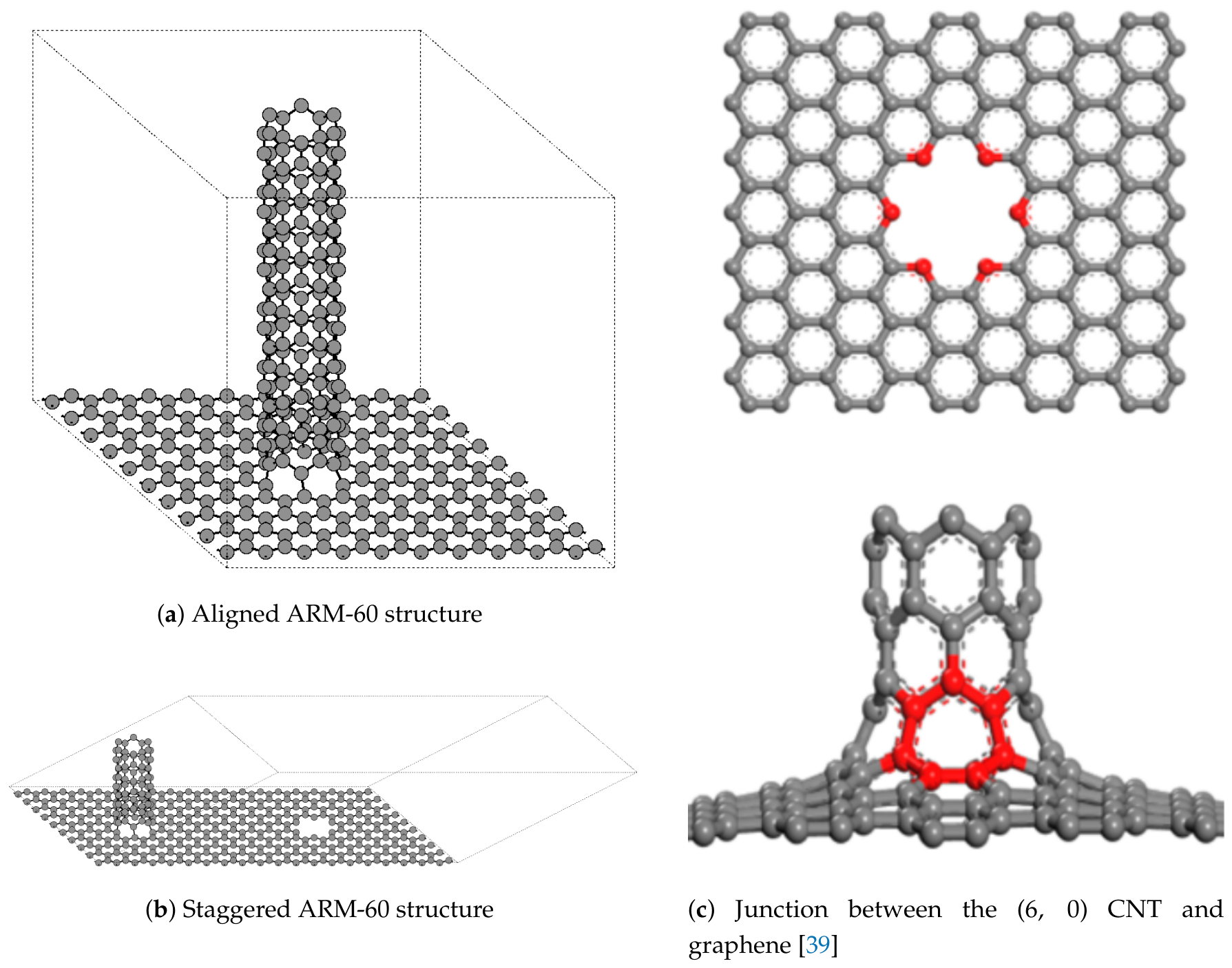
Figure 2.
Energy per atom of a) aligned and b) staggered ARM-60 structures during the stretching process. Energy reference set to the minimum value of the staggered structure. Separation is measured as the periodicity in the z axis minus the length of the nanotube divided by two.
Figure 2.
Energy per atom of a) aligned and b) staggered ARM-60 structures during the stretching process. Energy reference set to the minimum value of the staggered structure. Separation is measured as the periodicity in the z axis minus the length of the nanotube divided by two.
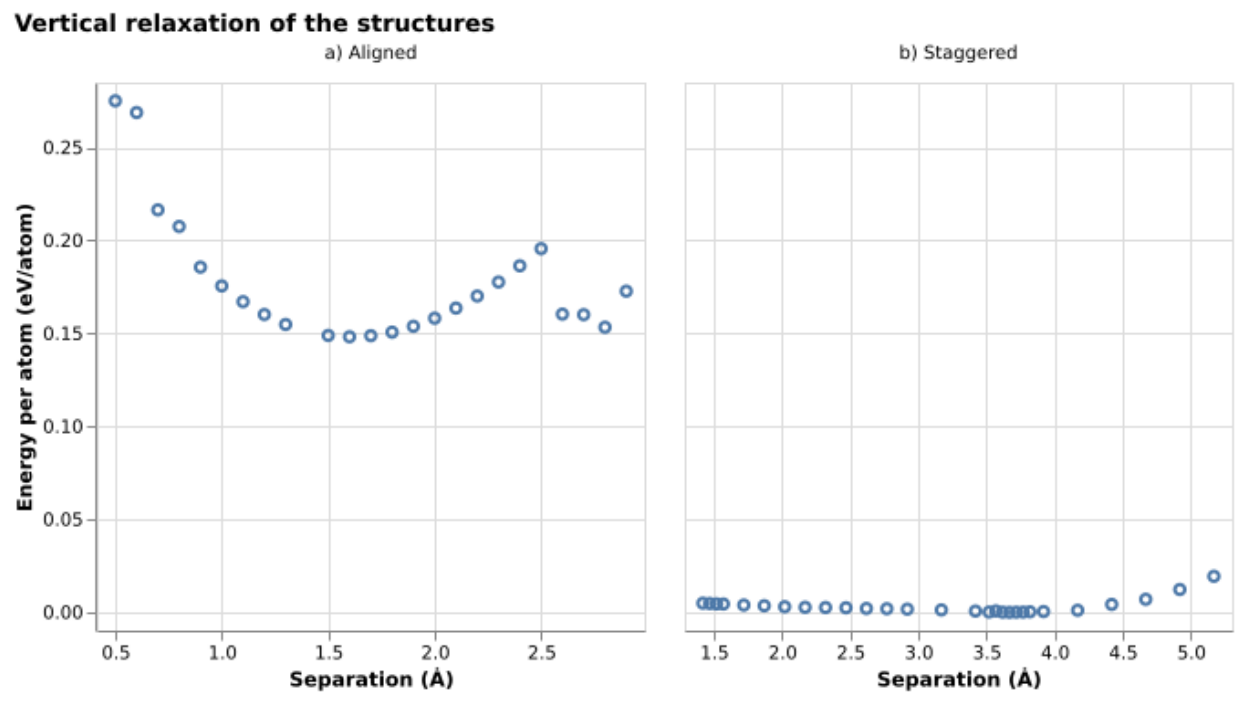
Figure 3.
Structures in Figure 1 after relaxation
Figure 3.
Structures in Figure 1 after relaxation
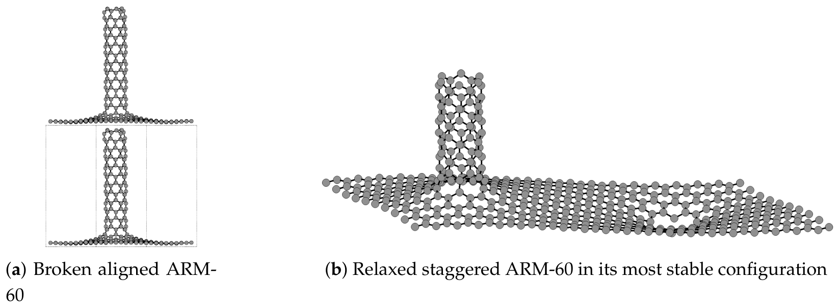
Figure 4.
Energy per atom of the staggered ARM-60 structure for different nanotube lengths. Energy reference set to the minimum for the length 1 structure.
Figure 4.
Energy per atom of the staggered ARM-60 structure for different nanotube lengths. Energy reference set to the minimum for the length 1 structure.
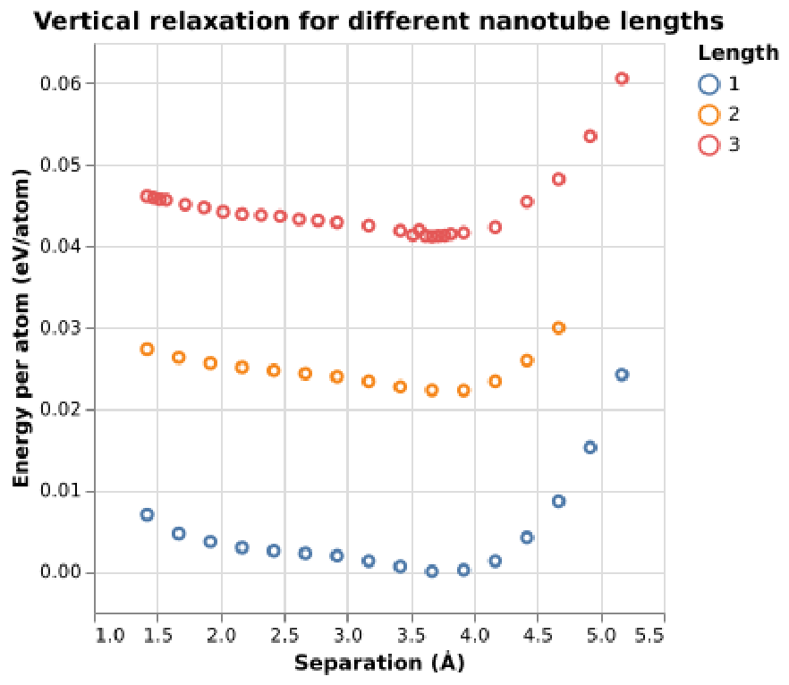
Figure 5.
All atomic positions that will be studied, split into their respective paths. Pink (blue) spheres represent the hollow (bridge) sites. (a) represents steps 0 to 10 from bottom to top. (b) represents steps 0 to 12 from left to right. (c) represents steps 0 to 8 from bottom to top.
Figure 5.
All atomic positions that will be studied, split into their respective paths. Pink (blue) spheres represent the hollow (bridge) sites. (a) represents steps 0 to 10 from bottom to top. (b) represents steps 0 to 12 from left to right. (c) represents steps 0 to 8 from bottom to top.
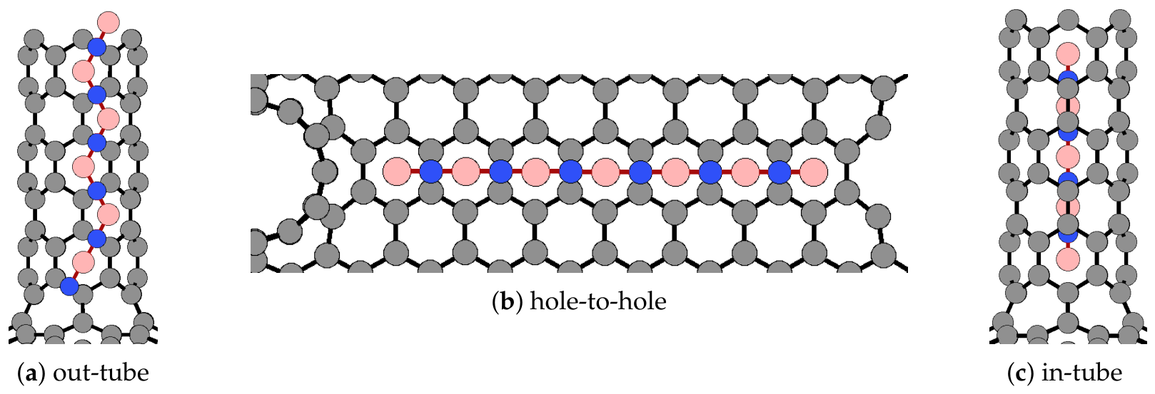
Figure 6.
Adsorption energy for the three paths presented in Figure 5 for a) lithium and b) sodium in the structure displayed in Figure 3b. In blue the hole to hole case, in red the inside CNT path and in yellow the movement of the Na/Li atom outside the CNT. Squares and circles correspond to hollow and bridge sites, respectively.
Figure 6.
Adsorption energy for the three paths presented in Figure 5 for a) lithium and b) sodium in the structure displayed in Figure 3b. In blue the hole to hole case, in red the inside CNT path and in yellow the movement of the Na/Li atom outside the CNT. Squares and circles correspond to hollow and bridge sites, respectively.
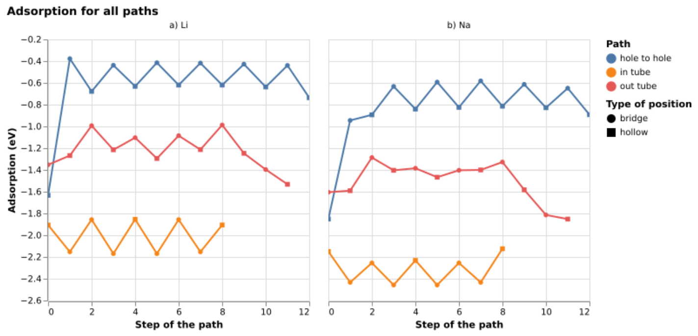
Figure 7.
Adsorption energy along the hole-to-hole path for each nanotube length, only for the sodium atom
Figure 7.
Adsorption energy along the hole-to-hole path for each nanotube length, only for the sodium atom
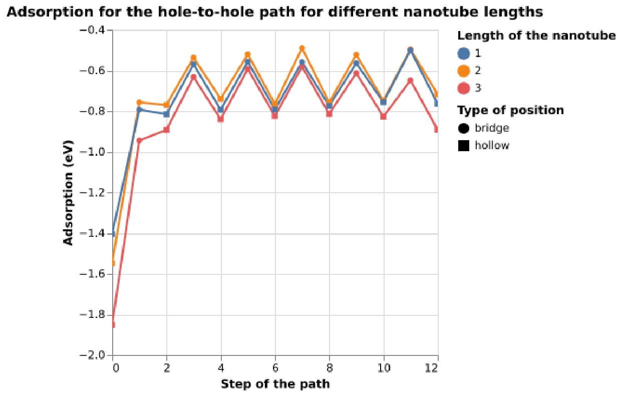
Figure 8.
Charge of the a) lithium and b) sodium atoms along the paths in Figure 5, corresponds to Figure 6
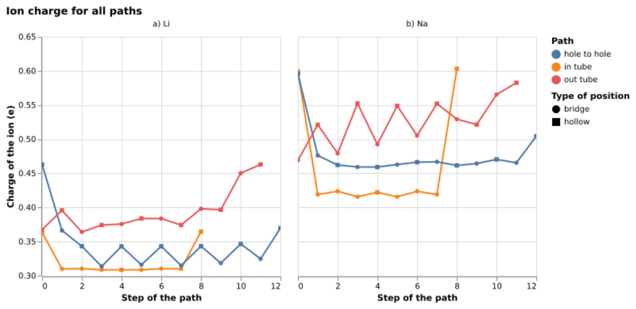
Figure 9.
Charge of the sodium atom along the hole-to-hole path for different nanotube lengths.
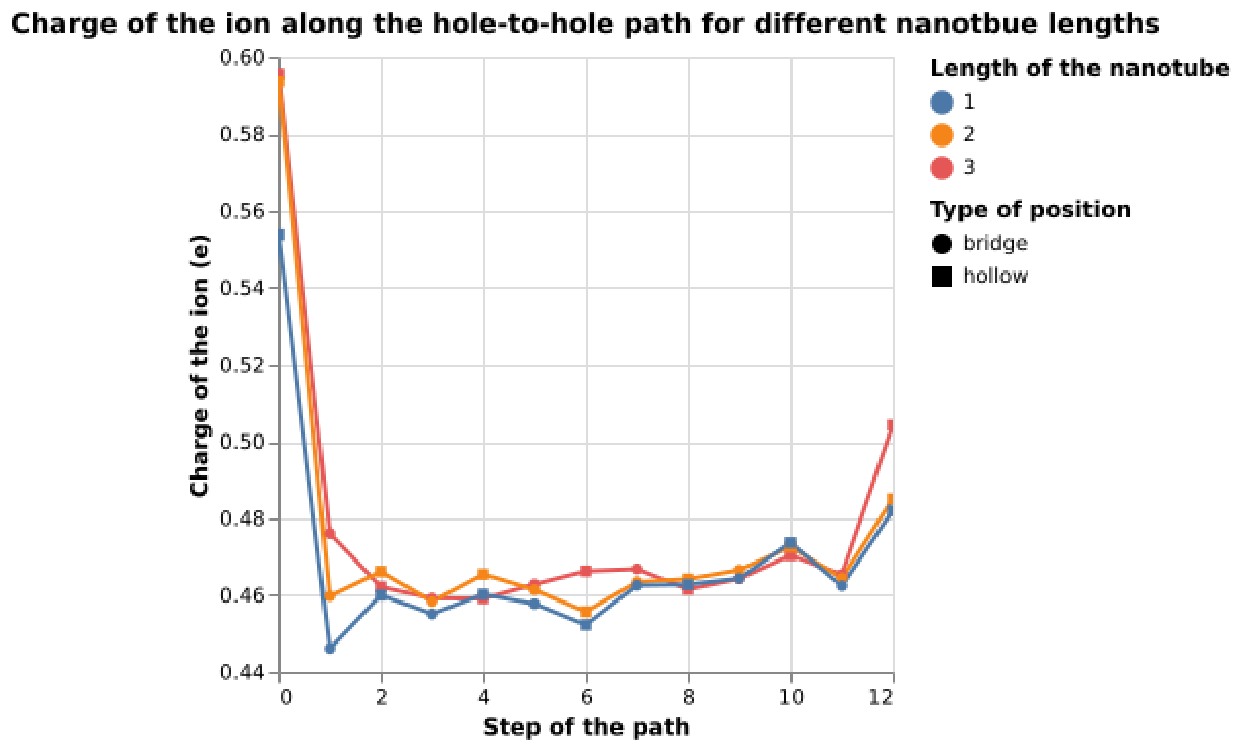

Table 1.
Averaged Migration barriers in eV for the paths in Figure 6, calculated as the difference between contiguous positions, averaged between steps 3-10 for hole-to-hole, 3-9 for out-tube and 2-7 for in-tube.
Table 1.
Averaged Migration barriers in eV for the paths in Figure 6, calculated as the difference between contiguous positions, averaged between steps 3-10 for hole-to-hole, 3-9 for out-tube and 2-7 for in-tube.
| hole-to-hole | out-tube | in-tube | |
|---|---|---|---|
| Na | 0.218 | 0.052 | 0.203 |
| Li | 0.183 | 0.203 | 0.308 |
Table 2.
Effect of nanotube length on unit cell periodicity, atom count, and migration barriers.
| Nanotube length | Periodicity in the z axis (Å) | Atoms in the unit cell | Migration barrier (eV) |
|---|---|---|---|
| 1 () | 10.18 | 412 | 0.233 |
| 2 () | 14.94 | 436 | 0.255 |
| 3 () | 18.70 | 460 | 0.208 |
Disclaimer/Publisher’s Note: The statements, opinions and data contained in all publications are solely those of the individual author(s) and contributor(s) and not of MDPI and/or the editor(s). MDPI and/or the editor(s) disclaim responsibility for any injury to people or property resulting from any ideas, methods, instructions or products referred to in the content. |
© 2026 by the authors. Licensee MDPI, Basel, Switzerland. This article is an open access article distributed under the terms and conditions of the Creative Commons Attribution (CC BY) license (http://creativecommons.org/licenses/by/4.0/).
Copyright: This open access article is published under a Creative Commons CC BY 4.0 license, which permit the free download, distribution, and reuse, provided that the author and preprint are cited in any reuse.