

Submitted:
13 August 2026
Posted:
14 August 2026
You are already at the latest version
Abstract
During the study of premixed NH₃/CH₄ fuel mixtures, flame separation into two reaction zones was observed upon flashback into a Bunsen burner. Stable combustion regimes were obtained, with a gap between the burner rim and the upper luminous region, the size of which depended on the mixture composition and the position of the combustion zone inside the burner. The influence of the equivalence ratio and the ammonia mole fraction on the separation effect was examined. At the burner exit, temperature and gas composition profiles were measured. Flame emission was recorded at the chemiluminescence bands of OH* (308 nm) and CH* (431 nm), and emission spectra were acquired both inside and outside the burner. Spectral analysis revealed a band corresponding to NO₂ emission in the upper part of the luminous region. It is most likely that nitrogen dioxide is formed through low temperature reactions occurring when the combustion products mix with atmospheric air.
Keywords:
laminar combustion
; Bunsen burner
; flame flashback
; ammonia-containing mixtures
; gas analysis
; chemiluminescence of OH* and CH* radicals
; flame emission spectrum
1. Introduction
Nearly two-thirds of the world’s energy is produced by burning carbon-based fossil fuels. This has led to an increasing need to address environmental problems associated with emissions of harmful substances, including greenhouse gases (NOx, CO2, CH4). The issues arising in the course of solving these problems are inextricably linked to decarbonization processes. The term “decarbonization” encompasses a wide range of directions for the development of industry, transport, science, and technology, such as renewable energy; low-carbon fuel energy; carbon capture from energy production; electrification of production; and improving energy efficiency of technologies [1,2]. One of the above methods for reducing CO2 emissions is the use of low-carbon or completely carbon-free fuels in the energy sector and power systems. As a carbon-free fuel, ammonia-hydrogen blends are considered promising [3,4]. However, it should be borne in mind that the production of ammonia is currently one of the most carbon-intensive processes in the global industry [5]. Its carbon footprint is directly dependent on the method of producing hydrogen, which is a key component for the synthesis of NH3. On a per unit basis, ammonia leaves almost twice the carbon footprint of steel and four times that of cement.
The idea of using ammonia as a fuel emerged quite a long time ago. One of the earliest pieces of evidence of ammonia being used as a fuel dates back to the late 19th century—a drawing by the American artist A.R. Waud (1881) depicting a tram with an ammonia-gas engine operating on a route in New Orleans. Also noteworthy is the Norwegian oil, gas, and metallurgical company Norsk Hydro Power, which in 1933 converted a small truck to run on hydrogen. The hydrogen was produced through ammonia reforming and fed into an internal combustion engine. In 1960, NASA introduced the X-15 rocket plane, equipped with an NH3-powered engine, which set speed (3,514 km/h) and altitude (41,605 m) records. More recently, a sign of progress in this field is the Chinese vessel Anhui, which successfully completed its first trial voyage in Hefei in June 2025, using ammonia as fuel. The tests confirmed stable fuel combustion with relatively low nitrogen oxide emissions. The vessel had a cargo capacity of up to 50 tonnes and an average cruising speed of 18 km/h.
Despite the clear progress in developing ammonia-based engine technologies, several challenges associated with this fuel type should be noted: low burning velocity and consequently, flame stabilisation issues; a narrow range of operating conditions (combustion near stoichiometry); and the need to neutralise residual ammonia in the combustion products in the case of fuel-rich mixtures [6]. In work [7], using a swirl burner under maximum efficiency conditions (minimum NO emissions with high combustion completeness), the equivalence ratio range was found to be φ=1.05–1.1. To extend the stability limits in terms of velocities and equivalence ratios, ammonia–hydrogen or ammonia–methane blends have been proposed. The properties of such blends are being actively studied [8,9,10,11].
Analysis has shown that the presence of ammonia in the mixture significantly complicates the chemical kinetics. Moreover, computational models often fail to adequately describe the behaviour of mixtures in the fuel-rich flame region, not only overpredicting NO emissions quantitatively but also showing qualitative disagreement with experiments [12,13,14], although the combustion of lean mixtures is modelled with reasonable accuracy. It should be noted that such physicochemical properties of reacting mixtures as the laminar flame speed, the critical velocity gradient at flashback, and the characteristic combustion time are key parameters in the analysis of thermodynamic processes, particularly in studying turbulent flame propagation [15]. The dimensionless parameter “burning velocity increment,” proposed in [16] for analysing the dependence of flame speed on fuel composition,
where is the flame speed, is the mole fraction of the active component (usually hydrogen), and is the equivalence ratio, has proven useful for hydrocarbon–hydrogen blends but has shown low effectiveness for ammonia-containing fuels. The use of the critical velocity gradient at adiabatic flashback gives more promising results. To approximate the “burning velocity increment” dependence on the mole fraction of the active component, the function
can be used, where the coefficient , 2.85, and 0.5 for CH4/H2, NH3/H2, and NH3/CH4, respectively, is determined through the critical flashback velocity gradient [17].
According to numerical modeling results [18], in fuel-rich regions of a swirling flame during oxygen-enriched ammonia combustion, NO and NO2 concentrations exceed equilibrium values. Unstable ammonia combustion regimes exhibit characteristic features. During flame blow-off, NO concentration decreases, while N2O and NO2 emissions increase. The increase in the latter is due to the fact that, under blow-off conditions, both the formation and consumption rates of these species decrease. However, owing to the temperature drop, the consumption rate falls faster than the generation rate, leading to the accumulation of NO2 and N2O. The obtained data indicate that the deterioration of emission characteristics during blow-off is a critical issue that must be taken into account when designing emission control systems.
The strategy for reducing NOx emissions during combustion of NH3/H2 mixtures is fundamentally different from that applied to hydrocarbons [19]. In the case of hydrocarbons, NOx emissions peak near stoichiometric conditions and decrease to equilibrium values with increasing residence time at reduced temperature in the reaction zone. This is due to the high-temperature mechanism of nitrogen oxide formation. For NH3/H2 mixtures, the main contribution comes from “unrelaxed” emissions; therefore, the concept of “rapid equilibrium attainment” is aimed at accelerating chemical relaxation without increasing residence time. Intense mixing is necessary for effective preheating, but it hinders the attainment of equilibrium. Accordingly, within this concept, mixing is maximised in the preheating zone and decreases monotonically as equilibrium is approached.
Flame flashback is one of the undesirable operating regimes of combustion chambers, and a considerable number of studies have been devoted to investigating the limiting conditions for its occurrence. In particular, in work [20], high-speed video recording of the flashback process in a rich 20% NH3/80% H2–air mixture (φ = 1.17) revealed a separation of the reaction zone into two regions: inside the burner and at its rim. The authors observed an unsteady process recurring at a frequency of ~10 Hz. It is assumed that a hydrogen combustion front propagates inside the burner, while at the rim, afterburning occurs, accompanied by NH2 emission over a broad spectral range (from 300 to 830 nm). The observed effect of reaction-zone separation during flashback into the burner attracted our attention.
This paper presents the results of an experimental investigation of combustion regimes of ammonia–methane mixtures accompanied by flashback and separation of the combustion zones. One of the tasks was to identify the nature of the luminescence in the combustion products downstream of the burner exit. To address this task, an integrated approach was employed, including gas analysis, chemiluminescence detection of OH* and CH* radicals, and flame emission spectroscopy inside the burner and beyond its edge.
2. Materials and methods
Figure 1 shows a schematic of the experimental setup. The fuel mixture preparation and flow control system (I) included cylinders of combustible gases NH3 and CH4 (99.99% purity) and a UFPGS-2 fuel mixture generator. The air supply system (II) consisted of a compressor with a receiver, a set of purification filters, and a flow meter. The experiments were carried out on a Bunsen-type burner (III), which was a long quartz tube with an inner diameter of mm and a length of mm, sufficient to establish Poiseuille flow at the exit (–, ). The fuel–air composition was set using the UFPGS-2 flow controller for the ammonia–hydrogen mixture and a Bronkhorst MassView air flow controller. Atmospheric air from the compressor at a pressure of 3.5 bar was supplied through a line to a system of three filters (AME 350C–F04, AME 350C–F04, AME 350C–F04–T) to prevent compressor oil vapour from entering the test section. The air then passed through a MassFlow meter before being mixed with the fuel. The fuel mixture composition and flow rates were adjusted to ensure a stationary position of the flame front. The volumetric concentrations of CO, CO2, H2, and O2 at the measurement point in the flame were determined using electrochemical sensors of a Test-1 gas analyser.
The gas sample was extracted using a quartz sampling probe with a diameter of 1.2 mm, whose position could be adjusted in the radial and vertical directions using a traversing mechanism. Prior to measurement, the sampled gas passed through a gas dryer, where water vapour was condensed in a Peltier cooler. A computer was used to control the precision gas flow regulator and to manage data acquisition.
The emission spectra of the flame were recorded using a Kolibri-2 spectrometer [21]. Radiation from the flame was collected by a collimator (focal length 17 mm, diameter 10 mm) aligned to focus a 5 mm diameter region of the flame onto the end face of a 1 mm diameter quartz fibre optic cable, the other end of which was connected to the spectrometer. Spectra in the range of 190–1080 nm were recorded with a resolution of 1 nm using a back-illuminated CCD array (2048 pixels, each 14×1000 µm in size). The acquisition time for a single spectrum was 500 ms. Spectral data processing was performed using Atom 3.3 software.
3. Results
During combustion of a premixed NH3/CH4/air mixture in a Bunsen burner under conditions close to flame flashback, regimes with the flame splitting into two reaction zones are observed (Figure 2). For a tube of given diameter , these conditions are determined by the mole fraction of ammonia in the binary fuel blend with methane, , the volumetric fuel flow rate , the volumetric air flow rate , the equivalence ratio , and the Reynolds number. The Reynolds number is defined as , where is the bulk flow velocity, is the tube diameter, and is the kinematic viscosity of the fuel–air mixture.
It was observed experimentally that there exists a range of mixture compositions and flow rates for which quasi-steady combustion conditions can be achieved during flashback. In this case, one of the combustion zones propagates upstream into the burner and stabilises on its inner surface. In modes b–d, two spatially separated reaction zones are observed: one inside the tube (referred to as the “lower” zone) and one outside (the “outer” zone). Between these zones, there is a region with no visible emission.
The deeper the lower combustion zone penetrates into the tube, the higher the outer luminous region rises above the tube end. As the dark gap between the tube end and the outer flame increases, the temperature at the burner exit decreases. Under the experimental conditions, the temperature was observed to drop from 1020 °C to 690 °C (see Figure 2). Flame separation during flashback is observed in both lean and rich mixtures (see photos in Figure 3). The gap observed between the burner rim and the “upper” luminous region (the reaction quenching zone near the tube end) is significantly smaller in the case of a rich mixture than in a lean one. The “lower” flame front has a curved shape, as the flow velocity exceeds the flame propagation speed. In the regimes studied, no oscillations of the flame front position were observed.
Figure 4 presents the results of temperature and composition measurements near the burner exit under the flame flashback conditions. The temperature in the “outer” flame region was measured using a type K thermocouple with a bead diameter of 0.1 mm. No correction for thermocouple radiation was applied. The temperature distribution has a bell-shaped profile; despite the visible front of the “outer” flame region, no local temperature maxima are observed (Figure 4a). The dried gas composition at the quartz tube exit is shown in Figure 4b. The CO2 content of approximately 8.6% indicates high combustion efficiency, which would correspond to complete combustion of methane in the “lower” flame front. As can be seen, for this combustion regime, a clear separation of the flame front into two distinct regions - an “outer” and a “lower” one -was observed in the visible range (see Figure 5a). Figure 5b shows the OH* chemiluminescence signal, which revealed only weak emission above the burner exit. The residual presence of OH* suggests that in the “lower” part of the flame, the oxidiser is consumed in the formation of fuel NO, reducing the content of the final product H2O. At the CH* radical wavelength, no signal is detected in this region (Figure 5c), indicating complete methane combustion within the burner flame front.
A typical emission spectrum of a laminar NH3/CH4/air flame under stoichiometric conditions with stabilisation at the rim is shown in Figure 6, where the characteristic lines of the main species typical of ammonia–methane–air flames are indicated [22,23]. The ratios of the measured intensities of the chemiluminescence lines of OH, NH, CN, and CH allow the equivalence ratio and the ammonia fraction in premixed ammonia–methane–air flames to be predicted [24,25].
Figure 7 presents the measured spectra of a premixed ammonia–methane flame at various equivalence ratios. As the equivalence ratio increases, the following characteristic changes can be observed in the spectra: a monotonic increase in the intensity of OH* and H2O lines in the separated (outer) flame, and the presence of a maximum for these lines () in the rim-stabilized flame without flashback. It is known that some molecules exhibit a continuous spectrum due to strong coupling between electronic and vibrational levels. For example, NO2 has a continuous spectrum in the visible range (400–800 nm) with a maximum around 600–700 nm (orange–red). NO2 absorbs in the blue-green region (~400–500 nm) and re-emits in the red region.
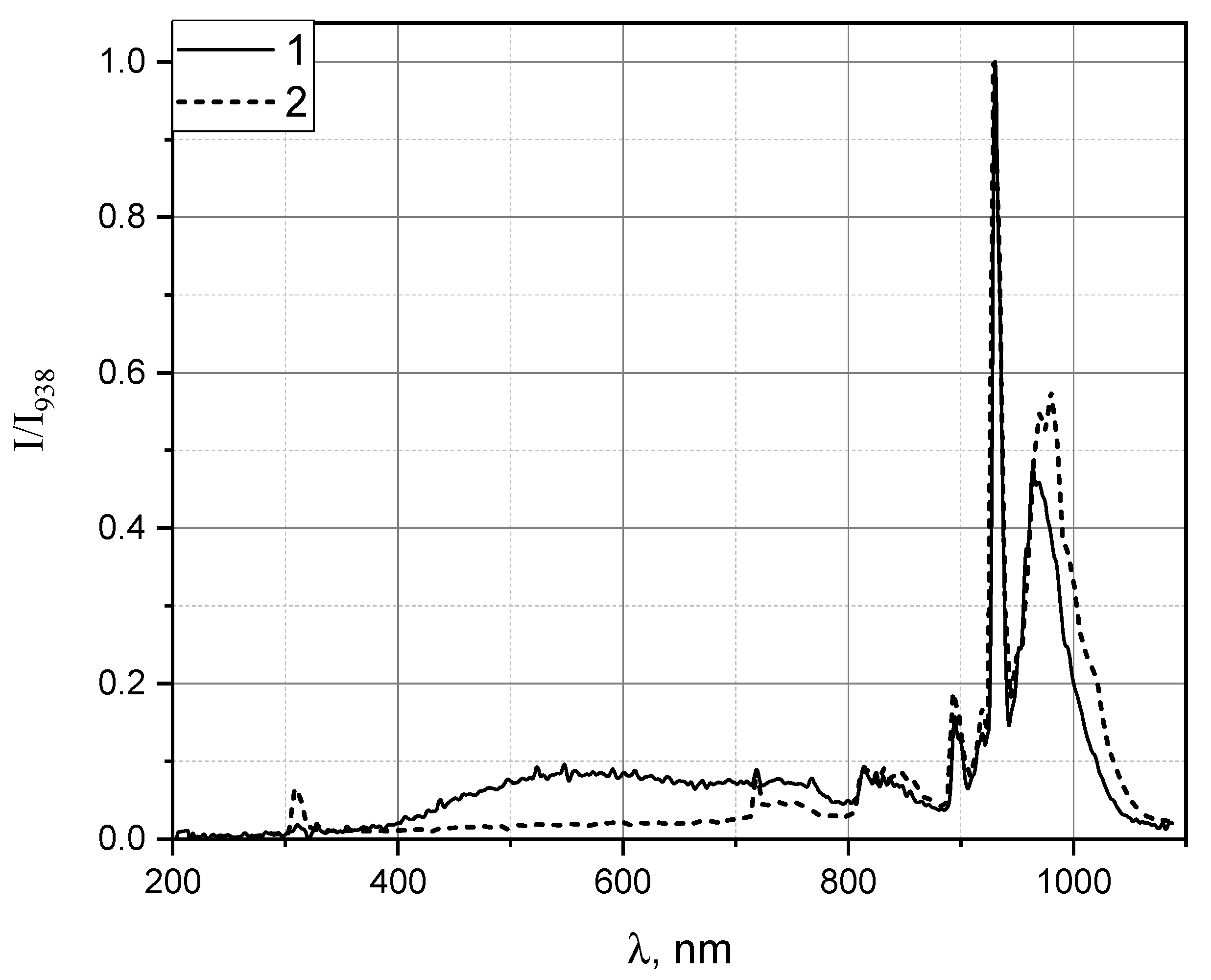
A comparison of the emission spectra of the combustion products for rim-stabilized (without flashback) and outer (quasi-flashback) flames is shown in Figure 8. The spectra are normalized to the line with maximum intensity in the recorded range (H2O at 938 nm). Traces of OH* emission (308 nm) are observed in the combustion products. In the 500–800 nm range, a significant difference between the spectra is observed, which is probably related to the presence of NO2 in the outer flame.
4. Discussion
As already noted, during combustion of premixed NH3/CH4/air mixtures in a Bunsen burner, an atypical regime may occur, namely, partial flame breakthrough into the burner, which we called quasi-flashback. In contrast to the results reported in [20] for NH3/H2/air mixtures, we obtained a nearly stationary separated flame under quasi-flashback conditions in NH3/CH4/air mixtures. This may have been possible because methane has a lower chemical reactivity than hydrogen. The range of velocities and compositions for this combustion scenario is rather narrow: φ = 0.95–1.1 and Re = 250–300. It should also be noted that a flame of a hydrocarbon–hydrogen mixture does not separate during flashback.
Temperature measurements in the “outer” flame region did not reveal any flame fronts, while the temperature of the combustion products decreases downstream in the outer reaction zone. Gas analysis results at the burner exit support the hypothesis of high combustion completeness in the “lower” flame front. The authors of [20] suggested that the outer reaction zone in the separated flame contains NH2, which is responsible for the orange colour of the luminous region. In our experiments with lean mixtures, this species cannot be present in significant amounts, yet luminescence is still observed.
The results of flame spectrometry deserve separate discussion. First, under quasi-flashback conditions for a premixed stoichiometric NH3/CH4/air mixture, the spectrum of the “lower” flame is completely identical to that of a flame stabilised at the rim of the Bunsen burner. In this experiment, the ammonia fraction in the binary NH3/CH4 fuel blend was by volume. It should be noted, however, that the “outer” reaction zone under quasi-flashback conditions is not analogous to the afterburning products behind a rich flame front.
In the wavelength range 500–800 nm, the emission spectrum of the “outer” flame of ammonia-containing fuel mixtures may contain lines of NO2 and NH2, which cannot be resolved separately. NH2 molecules, formed in significant amounts upon ammonia decomposition, can be present only during combustion of rich mixtures. The presence of NO2 is apparently associated with the low-temperature reaction occurring in the region where oxygen from the ambient air is mixed in [26].
In addition to emission band heads, absorption lines may also be of practical interest, such as, for example, H2O absorption at 942 nm. Comparison of the flame emission spectra shows that under the same conditions, a “dip” is observed in the “outer” flame near ~790 nm. In this range, both NH3 and HCN (hydrogen cyanide) absorb radiation intensely [22]. Since the fuel–air mixture composition corresponds to the stoichiometric ratio, the absorption is most likely caused by the formation of HCN, as an intermediate product reflecting the interaction between nitrogen and carbon chemistry. In NH3/CH4/air mixtures, the maximum mole fractions of HCN are located in the central part of the flame front stabilised at the burner rim [27].
5. Conclusions
Unlike classical adiabatic flashback, during quasi-flashback the flame front stabilises inside the tube (at some distance from the exit) and does not propagate downstream into the mixer. Visually, the flame front is observed to split into two parts: an inner zone (inside the burner) and an outer region above the exit. There is a gap between the burner exit and the afterburning region, which increases as the front moves upstream inside the tube. The temperature profile does not show the characteristic extrema of flame fronts.
Analysis of chemiluminescence showed that only OH* emission is detected above the burner exit, while no CH* radiation is present. This suggested that methane is completely consumed inside the tube, and only afterburning with OH* participation occurs in the outer zone. Chromatographic data confirm complete carbon oxidation inside the burner (absence of O2, presence of CO2 at maximum levels). The high NO content (>2000 ppm) is characteristic of ammonia combustion in lean mixtures.
According to flame emission spectra measurements, it was established that:
- under quasi-flashback conditions, the emission spectrum of the flame inside the burner has the same set of spectral lines as that of the rim-stabilised flame;
- the outer combustion region under quasi-flashback is not analogous to the afterburning zone behind a rich flame front;
- in the 500–800 nm wavelength range, the emission spectrum of the “outer” flame of ammonia-containing fuel mixtures most likely corresponds to NO2 emission, formed via the low-temperature reaction in the region where oxygen from the ambient air is entrained;
- the presence of an absorption line at ~790 nm in the quasi-flashback regime indicates HCN formation.
Quasi-flashback is a regime with pronounced non-equilibrium in combustion reactions, which is reflected in the composition of intermediate reaction products (NO, NO2, HCN).
Author Contributions
Conceptualization, Andrey Tupikin; Methodology, Vladimir Labusov and Igor Zarubin; Investigation, Vladimir Lukashov, Andrey Tupikin and Igor Zarubin; Writing – original draft, Vladimir Lukashov and Andrey Tupikin; Writing – review & editing, Vladimir Labusov. All authors have read and agreed to the published version of the manuscript.
Funding
The work was financially supported by the Ministry of Science and Higher Education of the Russian Federation, Agreement No. 075-15-2024-543 dated April 24, 2024.
Conflicts of Interest
The authors declare no conflicts of interest.
References
- Potashnikov, V.; Golub, A.; Brody, M.; Lugovoy, O. Decarbonizing Russia: Leapfrogging from Fossil Fuel to Hydrogen. Energies 2022, 15, 683. [CrossRef]
- Stavropoulos, P.; Panagiotopoulou, V. C. Carbon Footprint of Manufacturing Processes: Conventional vs. Non-Conventional. Processes 2022, 10, 1858. [CrossRef]
- Kobayashi, H.; Hayakawa, A.; Somarathne, K. D.; Okafor, E. Science and technology of ammonia combustion. Proceedings of the Combustion Institute 2019, 37, 109-133. [CrossRef]
- Frankl, S.; Gleis, S.; Karmann, S.; Prager, M.; Wachtmeister, G. Investigation of ammonia and hydrogen as CO2-free fuels for heavy duty engines using a high pressure dual fuel combustion process. International Journal of Engine Research 2020, 22, 3196–3208. [CrossRef]
- Boele, G.; Altaghlibi, M. What is the role of green ammonia in decarbonizing the world? https://assets.ctfassets.net/1u811bvgvthc/7ErTg1EUswtYB24RhddbqS/8d5bf65886b00708366ad31ce16d347b/241127_ESG_Economist_Green_Ammonia_ENG_final.pdf, 2024.
- Ma, F.; Guo, L.; Li, Z.; Zeng, X.; Zheng, Z.; Li, W.; Zhao, F.; Yu, W. A Review of Current Advances in Ammonia Combustion from the Fundamentals to Applications in Internal Combustion Engines. Energies 2023, 16, 6304. [CrossRef]
- Hayakawa, A.; Arakawa, Y.; Mimoto, R.; Somarathne, K. D. K. A.; Kudo, T.; Kobayashi, H. Experimental investigation of stabilization and emission characteristics of ammonia/air premixed flames in a swirl combustor. International Journal of Hydrogen Energy 2017, 42, 14010-14018. [CrossRef]
- Kumar, P.; Meyer, T. R. Experimental and modeling study of chemical-kinetics mechanisms for H2–NH3–air mixtures in laminar premixed jet flames. Fuel 2013, 108, 166-176. [CrossRef]
- Ichikawa, A.; Hayakawa, A.; Kitagawa, Y.; Somarathne, K. D. K. A.; Kudo, T.; Kobayashi, H. Laminar burning velocity and Markstein length of ammonia/hydrogen/air premixed flames at elevated pressures. International Journal of Hydrogen Energy 2015, 40, 9570-9578. [CrossRef]
- Okafor, E. C.; Naito, Y.; Colson, S.; Ichikawa, A.; Kudo, T.; Hayakawa A.; Kobayashi, H. Experimental and numerical study of the laminar burning velocity of CH4–NH3–air premixed flames. Combustion and Flame 2018, 187, 185-198. [CrossRef]
- Han, X.; Wang, Z.; Costa, M.; Sun, Z.; He Y.; Cen, K. Experimental and kinetic modeling study of laminar burning velocities of NH3/air, NH3/H2/air, NH3/CO/air and NH3/CH4/air premixed flames. Combustion and Flame 2019, 206, 214-226. [CrossRef]
- Konnov, A. A.; Dyakov I. V.; De Ruyck, J. Probe sampling measurements of NO in CH4/O2+N2 flames doped with NH3. Combustion Science and Technology 2006, 178, 1143–1164. [CrossRef]
- Brackmann, C.; Alekseev, V. A.; Zhou, B.; Nordström, E.; Bengtsson, P.-E.; Li, Z.; Aldén, M.; Konnov, A. A. Structure of premixed ammonia + air flames at atmospheric pressure: Laser diagnostics and kinetic modeling. Combustion and Flame 2016, 163, 370-381. [CrossRef]
- Rocha, R. C.; Zhong, S.; Xu, L.; Bai, X.-S.; Costa, M.; Cai, X.; Kim, H.; Brackmann, C.; Li, Z.; Aldén, M. Structure and Laminar Flame Speed of an Ammonia/Methane/Air Premixed Flame under Varying Pressure and Equivalence Ratio. Energy and Fuels 2021, 35, 7179–7192. [CrossRef]
- Douglas, C. M.; Polifke, W.; Lesshafft, L. Flash-back, blow-off, and symmetry breaking of premixed conical flames. Combustion and Flame 2023, 258, 113060. [CrossRef]
- Huang, Z.; Zhang, Y.; Zeng, K.; Liu, B.; Wang, Q.; Jiang, D. Measurements of laminar burning velocities for natural gas–hydrogen–air mixtures. Combustion and Flame 2006, 146, 302-311. [CrossRef]
- Lukashov, V.V.; Tupikin, A.V. Features of laminar combustion of NH3/CH4, NH3/H2 and CH4/H2 mixtures: critical conditions during flame blockage and flame propagation velocity. Combustion, Explosion and Shock Waves 2027. ().
- An, Z.; Wang, R.; Mao, R.; Xing, J.; Zhang, M.; Chen, Z. X.; Kurose, R. Flame stability and emission characteristics of oxygen-enriched ammonia combustion in a swirl combustor. Energy 2025, 324, 135829. [CrossRef]
- Colmán, H. M.; Mueller, M. E. Rush-to-equilibrium concept for minimizing reactive nitrogen emissions in ammonia combustion. Combustion and Flame 2025, 275, 114049. [CrossRef]
- Goldmann, A.; Dinkelacker, F. Investigation of boundary layer flashback for non-swirling premixed hydrogen/ammonia/nitrogen/oxygen/air flames. Combustion and Flame 2022, 238, 111927. [CrossRef]
- Zarubin, I. A.; Labusov, V. A.; Babin, S. A. Characteristics of Compact Spectrometers with Diffraction Gratings of Different Types. Inorganic Materials 2020, 56, 1436–1440. [CrossRef]
- Pearse, R. W. B.; Gaydon, A. G. The Identification of Molecular Spectra, Springer Dordrecht, Germany,1976.
- Rothman, L. S.; Gordon, I. E.; Barber, R. J.; Dothe, H.; Gamache, R. R.; Goldman, A.; Perevalov, V. I.; Tashkun, S. A.; Tennyson, J. HITEMP, the high-temperature molecular spectroscopic database. Journal of Quantitative Spectroscopy and Radiative Transfer 2010, 111, 2139-2150. [CrossRef]
- Guiberti, T. F.; Shohdy, N. N.; Cardona, S.; Zhu, X.; Selle, L.; Lapeyre, C. J. Chemiluminescence- and machine learning-based monitoring of premixed ammonia-methane-air flames. Applications in Energy and Combustion Science 2023, 16, 100212. [CrossRef]
- Mashruk, S.; Zhu, X.; Roberts, W. L.; Guiberti, T. F.; Valera-Medina, A. Chemiluminescent footprint of premixed ammonia-methane-air swirling flames. Proceedings of the Combustion Institute 2023, 39, 1415–1423. [CrossRef]
- Glarborg, P.; Kubel, D.; Kristensen, P. G.; Hansen, J.; Dam-Johansen, K. Interactions of CO, NOх and H2O Under Post-Flame Conditions. Combustion Science and Technology 1995, 1, 461–485. [CrossRef]
- Slastnaya, D. A.; Khrebtov, M.Yu.; Dulin, V. M. Numerical modeling of flame structure of premixed NH3/CH4/air mixture and NOx formation using detailed chemical-kinetic mechanisms. Combustion, Explosion and Shock Waves 2026, 19, 23-34. [CrossRef]
Figure 1.
Schematic diagram of the experimental setup: I – fuel mixture preparation and flow control system (NH3/CH4); II – air supply system; III – Bunsen burner; IV – gas analyser equipped with a sampling probe; V – spectrometer.
Figure 1.
Schematic diagram of the experimental setup: I – fuel mixture preparation and flow control system (NH3/CH4); II – air supply system; III – Bunsen burner; IV – gas analyser equipped with a sampling probe; V – spectrometer.
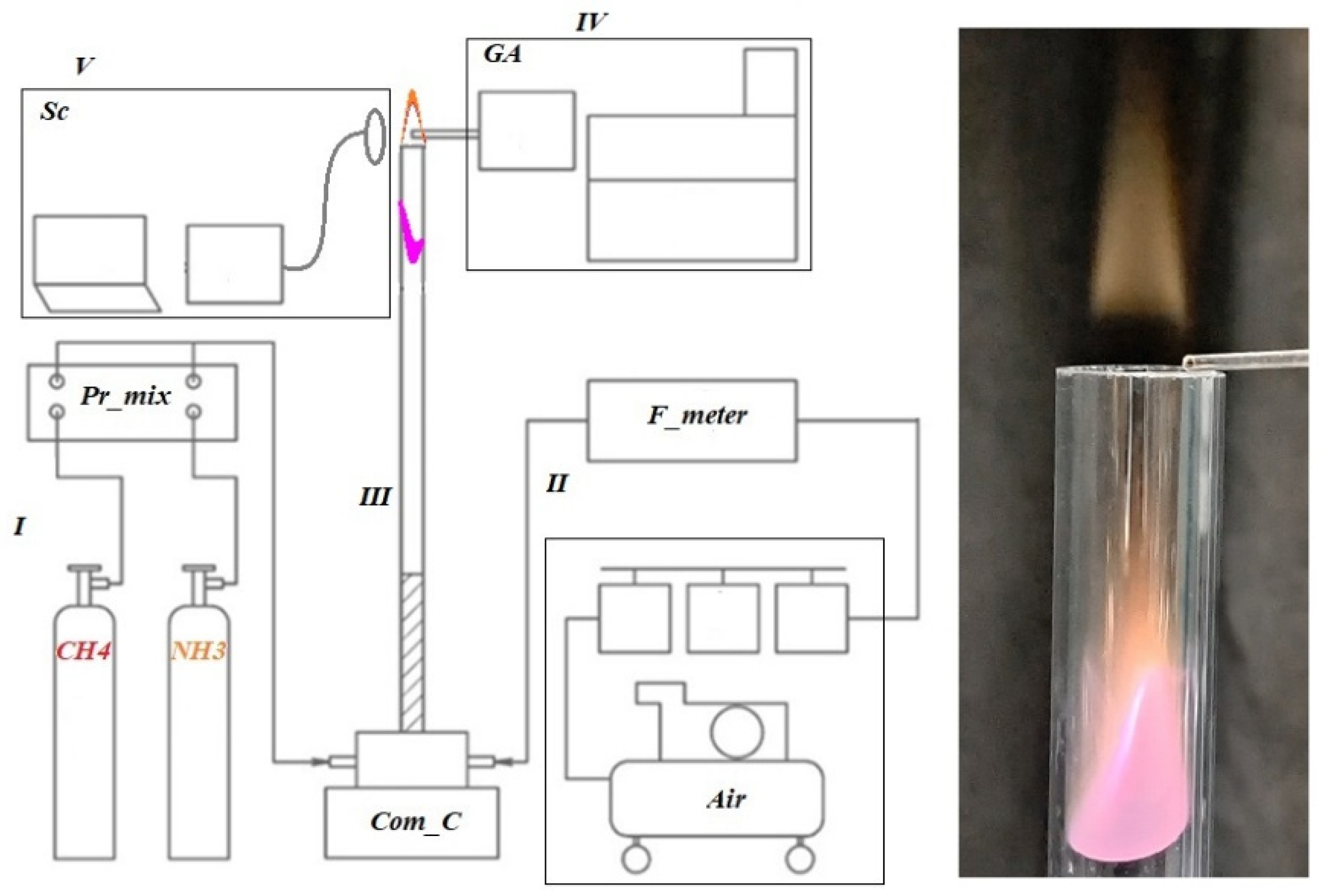
Figure 2.
Combustion regimes of the separated NH3/CH4/air flame. , slm, slm, , .
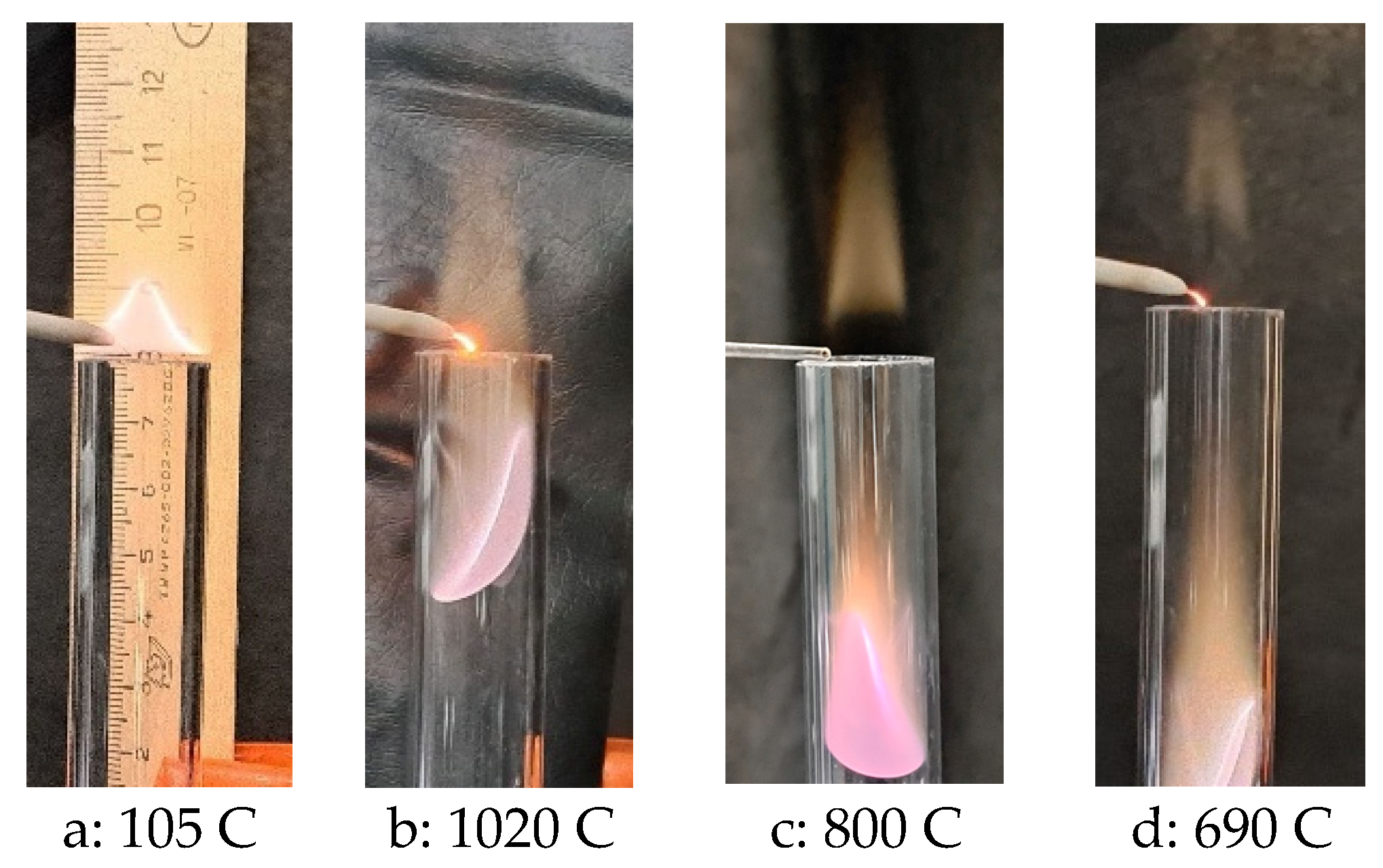
Figure 3.
Separation of the reaction zone as a function of the fuel–air mixture composition. , , slm.
Figure 3.
Separation of the reaction zone as a function of the fuel–air mixture composition. , , slm.
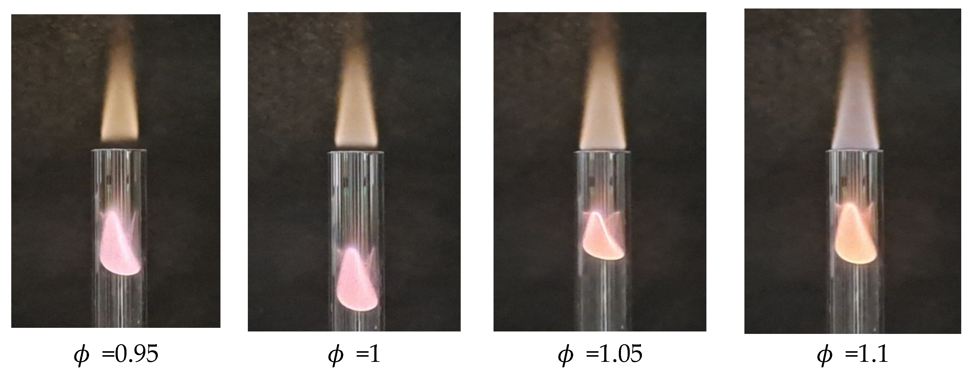
Figure 4.
Distributions of temperature (a) and gas composition (b) at the burner rim under the separated flame conditions. , .
Figure 4.
Distributions of temperature (a) and gas composition (b) at the burner rim under the separated flame conditions. , .
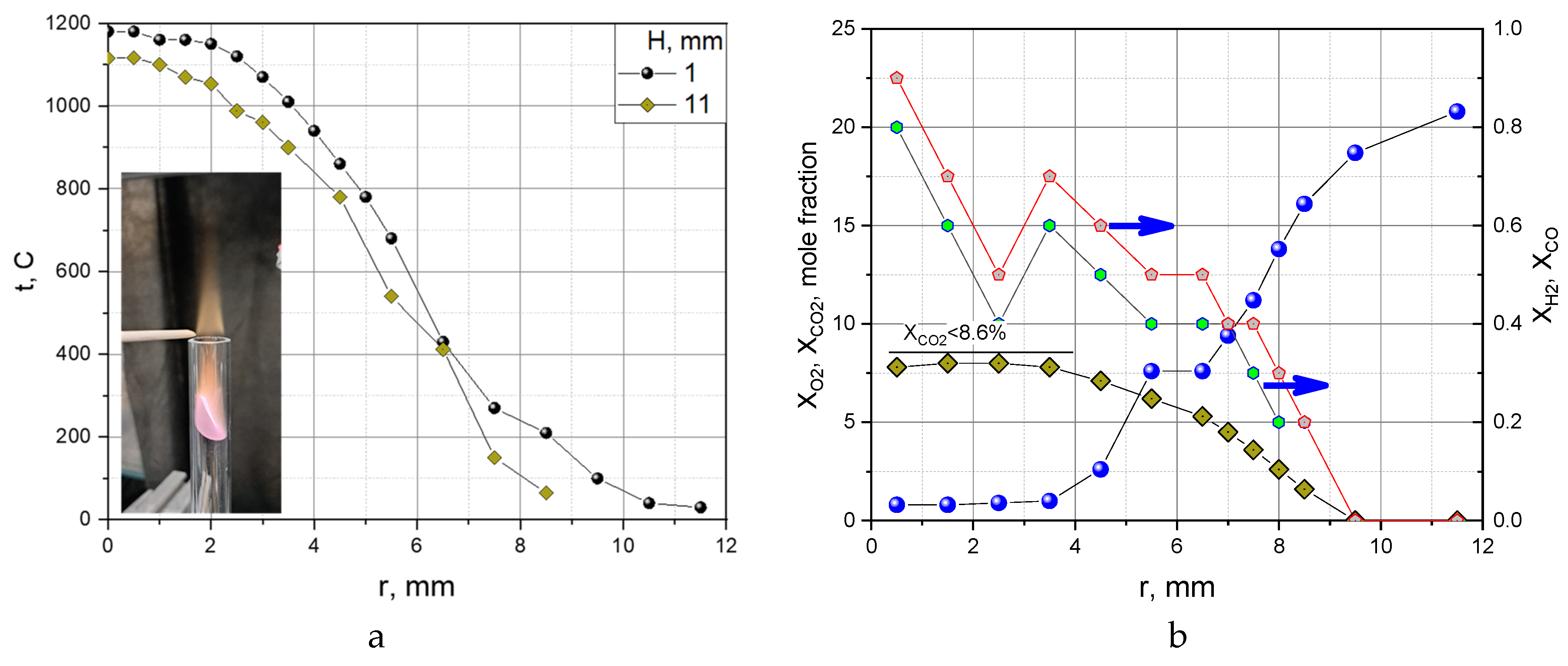
Figure 5.
Flame registration during stagnation of stoichiometric mixture (fuel: 40% NH3, 60% CH4): a – visible range; b – OH* chemiluminescence (negative); c – CH* chemiluminescence (negative).
Figure 5.
Flame registration during stagnation of stoichiometric mixture (fuel: 40% NH3, 60% CH4): a – visible range; b – OH* chemiluminescence (negative); c – CH* chemiluminescence (negative).
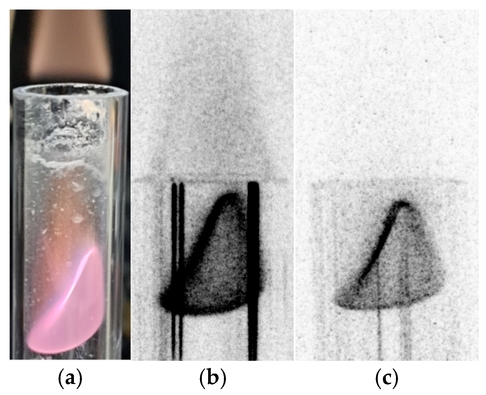
Figure 6.
Emission spectrum of a laminar Bunsen-type flame for a stoichiometric NH3(40%)/CH4/air mixture.
Figure 6.
Emission spectrum of a laminar Bunsen-type flame for a stoichiometric NH3(40%)/CH4/air mixture.
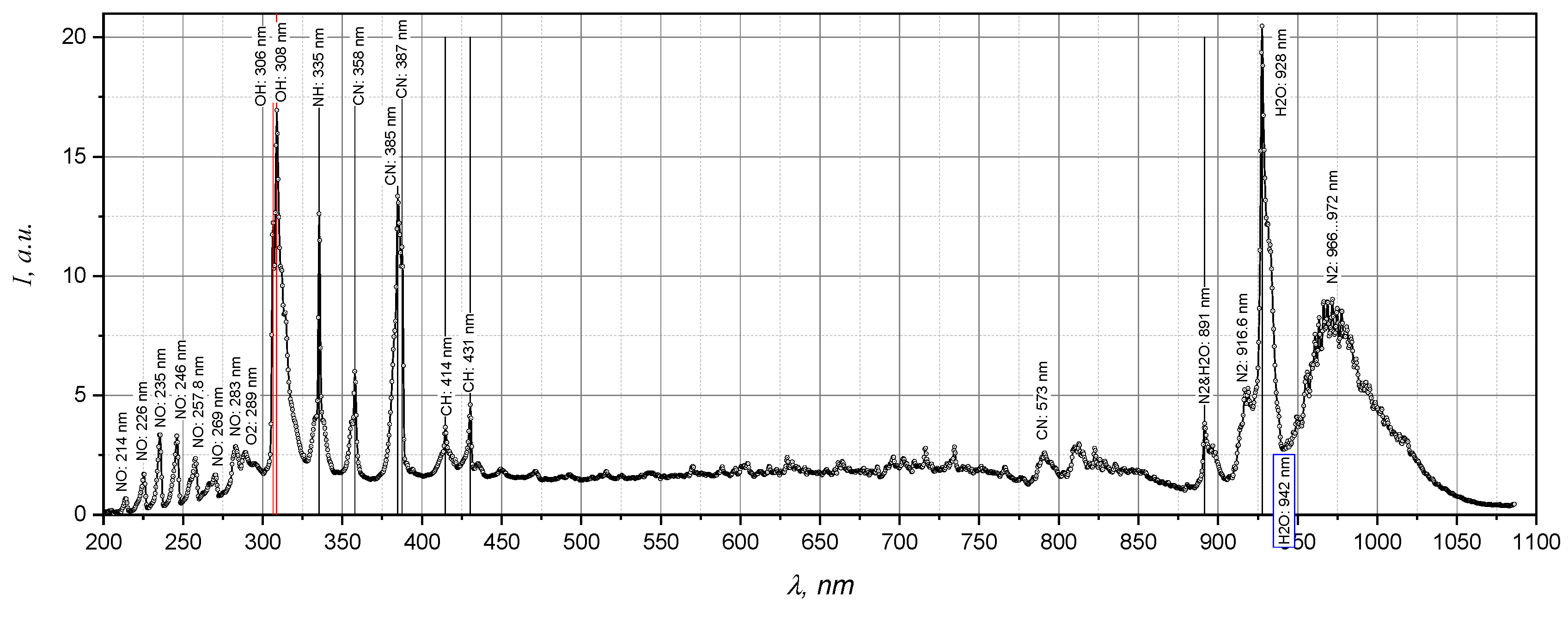
Figure 7.
Comparison of emission spectra of the separated (a) and rim-stabilized (b) flames. , , mm.
Figure 7.
Comparison of emission spectra of the separated (a) and rim-stabilized (b) flames. , , mm.
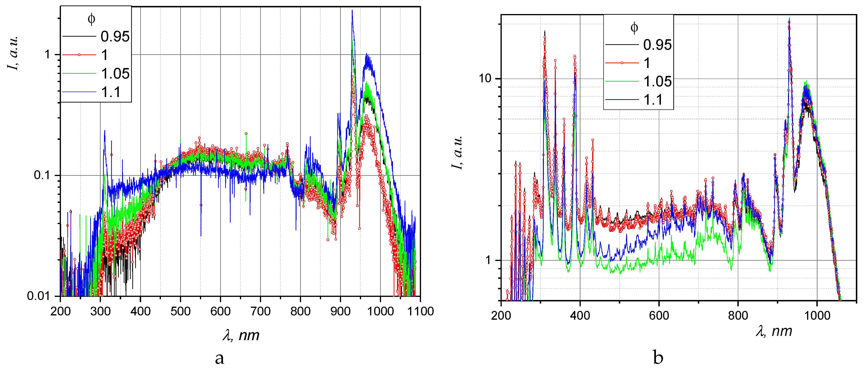
Figure 8.
Comparison of the emission spectra of the separated flame (2) and the combustion products of the rim-stabilized flame. , , mm.
Figure 8.
Comparison of the emission spectra of the separated flame (2) and the combustion products of the rim-stabilized flame. , , mm.
Disclaimer/Publisher’s Note: The statements, opinions and data contained in all publications are solely those of the individual author(s) and contributor(s) and not of MDPI and/or the editor(s). MDPI and/or the editor(s) disclaim responsibility for any injury to people or property resulting from any ideas, methods, instructions or products referred to in the content. |
© 2026 by the authors. Licensee MDPI, Basel, Switzerland. This article is an open access article distributed under the terms and conditions of the Creative Commons Attribution (CC BY) license (http://creativecommons.org/licenses/by/4.0/).
Copyright: This open access article is published under a Creative Commons CC BY 4.0 license, which permit the free download, distribution, and reuse, provided that the author and preprint are cited in any reuse.