

Submitted:
12 August 2026
Posted:
12 August 2026
You are already at the latest version
Abstract
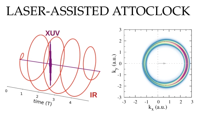
We present a theoretical investigation of the attoclock method in laser-assisted photoemission (LAPE) processes. We analyze atomic photoionization driven by a short XUV pulse assisted by a circularly polarized strong infrared (IR) laser under accessible experimentally conditions. We calculate three-dimensional photoelectron momentum distributions (PMDs) in order to extract time delays from their angular information based on the attoclock principle. Furthermore, we explore different XUV parameters to determine the optimal achievable temporal precision for the laser-assisted attoclock (LAAC). The analyses performed within the the strong-field approximation (SFA) are further supported by improved Coulomb methods, including the Coulomb–Volkov approximation (CVA) and numerical solutions of the time-dependent Schrödinger equation (TDSE). Our work lays a theoretical foundation for understanding time-resolved electronic dynamics in cutting-edge ultrafast experiments of photonic collisions.
Keywords:
att
; attoclock
; laser-assisted
; photoionization
; strong-field
; time-resolved
1. Introduction
Attosecond science has established photoelectron spectroscopy as one of the most direct routes to access electronic motion on its native, attosecond, time scale. In particular, attosecond streaking maps the time of extreme ultraviolet (XUV)-induced photoemission onto a final photoelectron momentum shift imposed by a phase-controlled linearly polarized infrared (IR) field. More specifically, the electron is released near the maximum of the electric field, while its final drift momentum is approximately determined by the instantaneous vector potential at the ionization time, thereby, temporal information is transduced into a measurable spectrogram [1,2,3,4,5,6]. A closely related concept is the attoclock, where an intense elliptically or circularly polarized laser field acts as an ultrafast angular streak camera: The angular offset of the photoelectron momentum distribution (PMD) can then be interpreted, within a suitable model, as a time delay [7,8,9,10,11]. This interpretation has stimulated considerable debate on tunneling times, Coulomb-laser coupling, nonadiabatic effects, and the precise operational meaning of the measured angular shift [10,11,12,13]. Overall, the attoclock remains a powerful paradigm converting the angular structure of a PMD into subcycle timing information.
Laser-assisted photoionization emission (LAPE) provides a complementary route to attosecond metrology. In LAPE, an XUV pulse ionizes the target while a synchronized IR field modifies the outgoing electron wave packet, leading to sidebands, streaking shifts, and interference structures in the photoelectron spectrum [4,5,14,15,16]. Depending on the relative duration of the XUV and IR fields, LAPE can operate in different regimes. For isolated attosecond XUV pulses, the IR field acts predominantly as a streaking probe, and the final momentum shift encodes the vector potential at the time of photoemission. For longer XUV pulses or attosecond pulse trains, the electron may be emitted over several IR cycles, giving rise to sideband formation due to intercycle interferences [17,18,19]. In this sense, LAPE connects attosecond streaking, sideband spectroscopy, and quantum-path interference within a unified XUV–IR photoionization framework.
Recent theoretical works has clarified several structural aspects of LAPE spectra. Semiclassical and strong-field approximation (SFA) analyses have shown that the photoelectron spectrum can often be decomposed into contributions associated with intra- and intercycle interferences regarding symmetry properties of the transition matrix [17,18,19,20]. In particular, few years ago we examined atomic LAPE in streaking, sideband, and attosecond-pulse-train regimes, showing how generalized energy-conservation rules and interference factors organize the observed photoelectron structures [19]. More recently, extensions beyond the dipole approximation have demonstrated that nondipole corrections can break forward–backward symmetries and modify angular emission patterns in circularly polarized LAPE configurations [21,22]. These developments indicate that does LAPE not only lead to a pulse-characterization technique, but also to a sensitive probe of emission timing, angular streaking, and continuum electron dynamics.
In this work, we explore whether LAPE driven by a circularly polarized IR field can be used as an attoclock. The central idea is to use the angular information contained in the PMD to infer the value of the IR vector potential at the time of XUV-induced ionization and, more importantly, to infer the time delay of the photoionization process. In the ideal limit of the simpleman’s model, a sufficiently short XUV pulse selects a narrow time window, and the final electron momentum approximately follows , where is the initial photoelectron momentum in the absence of the IR field, is the IR vector potential at the ionization time , and is the measured asymptotic momentum. For a rotating vector potential, different ionization times correspond to different emission angles. Therefore, measuring angular shifts in the PMD may allow one to reconstruct the emission time within the IR optical cycle, in direct analogy with the attoclock principle [7,8,10,23]. However, this mapping is expected to degrade as the XUV pulse duration increases, since ionization then occurs over a broader range of IR phases. In contrast with conventional attoclock measurements based on tunnel ionization, the present laser-assisted attoclock (LAAC) scheme uses XUV photoionization as a well-defined temporal probe [24]. The temporal resolution is determined by the XUV pulse duration, while the angular streaking is controlled by the rotation of the IR vector potential.
In this contribution, we present a theoretical investigation of the attoclock method in the LAPE process. Using the strong-field approximation, we analyze atomic photoionization driven by a short XUV pulse assisted by a strong circularly polarized IR laser under experimentally relevant conditions. Based on the attoclock principle, we investigate how to interpret the PMDs in order to extract temporal resolution from their angular information. We further explore different XUV parameters, including polarization and duration to determine the optimal achievable temporal precision of the LAAC. The SFA analysis is supported by improved Coulomb-sensitive approaches, including the Coulomb–Volkov approximation and the numerical solutions of the time-dependent Schrödinger equation (TDSE). Differences in the angular distributions between the CVA and SFA calculations provide an angular shift due to the effect of the Coulomb attraction of the parent ion on the photoelectron, which, can be directly interpreted as a time delay. Our work lays a theoretical foundation for using circular or elliptical LAPE as an angular streaking scheme for time-resolved electronic dynamics in ultrafast photon-collision experiments.
The paper is organized as follows: In Section 2, we describe the theoretical approaches, based both on the SFA and CVA, to evaluate the PMDs along the polarization direction in the LAAC protocol. The semiclassical model relying on the saddle-point approximation for well-defined semiclassical electron trajectories is introduced here as well. In Section 3, we present the results of the SFA and compare them to the CVA and ab initio calculations of the TDSE. Concluding remarks are presented in Section 4. Atomic units are used throughout the paper, unless otherwise stated.
2. Materials and Methods
We consider LAPE from an atomic system induced by the interaction of an XUV pulse with a strong IR laser field. The IR field acts as a streaking field that modifies the final momentum of the emitted photoelectron. Throughout this work, we restrict ourselves to the electric dipole approximation, where the electric fields are assumed spatially homogeneous and the interaction depends only on time. Within the single-active-electron (SAE) approximation, the electron dynamics is described by the TDSE
where is the field-free atomic Hamiltonian. The interaction with the external fields is written in the length gauge as , where and denote the electric fields of the IR and XUV pulses, respectively.
The electron, initially in the bound state with ionization potential , is emitted into a continuum state with asymptotic momentum and kinetic energy . The PMD is obtained from the transition amplitude
Within the time-dependent distorted-wave formulation, the transition amplitude in the prior form reads
where represents the distorted continuum final state including the interaction with the laser field [25].
A convenient approximation for the continuum wave function is provided by the Coulomb–Volkov description,
which accounts for both the laser-driven motion of the electron and the residual Coulomb interaction with the ionic core [25,26,27,28]. In Equation (4), the factor accounts for the Coulomb distortion of the continuum electron, with the Coulomb normalization factor , where 1 designates the confluent hypergeometric function and Z is the asymptotic charge of the parent ion. Neglecting the effect of the Coulomb potential of the residual ionic core on the photoelectron, as , one recovers the usual SFA, where the continuum electron is solely described by the Gordon–Volkov solution
with the instantaneous kinetic momentum . Although the SFA neglects the Coulomb interaction after ionization, it provides a very good description of LAPE spectra and allows a transparent interpretation in terms of electron trajectories and ionization times.
The electric field of an elliptically polarized IR field propagating along the z direction can be written as
where and are the peak electric-field amplitude and frequency of the IR pulse, respectively, and the parameter controls the ellipticity of the field. Throughout this work, denotes linear polarization, whereas denotes right-handed circular polarization. The associated vector potential field is obtained from and becomes
For the XUV pulse we consider a linearly polarized isolated attosecond pulse. The electric field is assumed to be short compared with the IR optical period and can be written as
where is the XUV polarization direction and defines its main carrier frequency. The temporal envelope is centered at the time and is defined by
The vector potential of the total field can then be written as . Since the interaction Hamiltonian contains contributions from the IR and XUV fields, the transition amplitude can be separated as
where the two terms describe the ionization induced by the IR and XUV fields, respectively.
The physical situation considered here corresponds to the streaking regime: the XUV pulse acts as an ultrashort ionization pump, while the IR field probes the released wavefunction, mapping the emission time of the electron into its final momentum distribution. To obtain the main physical features of LAPE, we consider that the XUV photon energy is much larger than the IR frequency. Therefore, two approximations can be made: (i) the vector potential associated with the XUV pulse is considered to be much smaller than that of the IR field, i.e., , and therefore the total vector potential entering the Volkov phase can be approximated due to only the IR pulse . And (ii), the ionization induced by each field, and , are spectrally well separated from each other (see for example [29]). Then, for the case of absorption of a single XUV photon we do not consider the contribution corresponding to ionization by the IR pulse , and only take into account
where the generalized action contains the Volkov action
In Equation (11) we have restricted the time integral to the nonzero envelope interval, and
contains the XUV polarization and the transition dipole matrix element given by , where is the initial electronic state and a normalized plane wave .
2.1. Semiclassical Analysis
The streaking regime is characterized by an XUV duration shorter than the IR optical period, . Consequently, the ionization process occurs within a narrow temporal window around . The integral in Equation (11) can then be evaluated using the saddle-point approximation. The stationary condition identifies the dominant emission time with the center of the XUV pulse, . Using Equation (12), it becomes
where . The saddle-point condition becomes the central equation of the semiclassical model (SCM), which determines the locus of the photoelectron momenta associated with a given ionization time ; i.e.,, a spherical surface in the momentum space wiht radius and center . Equation (14) provides the intuitive picture of the streaking mechanism. In the absence of the IR field, the electron is emitted with a momentum magnitude . The IR field modifies the final momentum through the instantaneous vector potential at the emission time. Therefore, the PMD is displaced by . Thus, measuring the displacement of the PMD directly provides information about the value of the vector potential at the instant of ionization.
Within the saddle-point approximation, the semiclassical transition amplitude can be written as
with the corresponding PMD given by
where .
For linearly polarized IR fields, oscillates along the polarization axis. Consequently, the streaking displacement in Equation (14) moves back and forth the momentum distribution along this direction. Different emission times therefore produce different translations of the PMD along the polarization axis. This is schematized in Figure 1(a), where the intersection between the momentum sphere defined by the SCM and the plane is shown for different values of the ionization times, namely , , and , as black, red, and blue circles, respectively. During the laser cycle, the center of the momentum sphere oscillates linearly between and . These turning points are marked by the red and blue dots, whereas the red and blue arrows indicate the center of the corresponding circumference. The PMD therefore oscillates between two opposite displacements within an IR cycle, during which it sweeps the momentum-space region shaded in green.
The situation changes qualitatively for circular polarization (see for example [24]). In this case, the vector potential rotates in the polarization plane with period T and the displacement rotates continuously within the optical cycle. Figure 1(b) shows this situation. Here, the green line defines the path followed by as function of in the plane; in addition, three different SCM PMD profiles corresponding to ionization times , and in black, red, and blue colors, respectively, are included. Over one optical period, the curve sweeps out the green-shaded region. Consequently, the electron emission angle provides a direct measure of the ionization time, which constitutes the central principle of the LAAC.
The SCM therefore provides the simplest physical interpretation of the LAAC: the field acts as an ultrafast momentum gate, where the instantaneous vector potential converts temporal information contained in the XUV excitation into measurable angular information in the final PMD. This constitutes the foundation of the attoclock concept, in which the photoelectron emission angle directly encodes the sub-cycle ionization time. Unlike the conventional attoclock, where this mapping arises from tunnel ionization, the present approach is based on a different ionization mechanism. As a representative example, for an driving laser the optical period is approximately . Since one full optical cycle corresponds to , an angular displacement of just represents a temporal interval of . Thus, each degree in the photoelectron emission angle corresponds directly to an attosecond-scale change in the ionization time, showing the high temporal sensitivity of the attoclock technique.
3. Results and Discussion
In this section, we present photoelectron momentum distributions (PMDs) for laser-assisted photoionization of ground-state hydrogen in the streaking regime. We first examine the separate contributions of the XUV and IR fields to the total ionization probability and benchmark the strong-field approximation (SFA) and Coulomb–Volkov approximation (CVA) against the numerical solution of the time-dependent Schrödinger equation (TDSE). We then investigate the role of the relative polarization directions and introduce the laser-assisted attoclock (LAAC) configuration.
Unless otherwise stated, we employ the following field parameters. For the IR field, we use a.u., corresponding to a wavelength of 800 nm, a.u., corresponding to an intensity W/cm2, and a pulse duration , where . The IR pulse has a flat-top envelope over the temporal interval in which the XUV pulse acts. For the XUV field, we choose , corresponding to a wavelength of approximately 38 nm, a.u., and . The XUV pulse has a -shaped envelope centered at the ionization time [see Equation (9)].
3.1. Linear Polarization: Comparison Among the TDSE, CVA, and SFA
We first consider the streaking configuration in which both fields are linearly polarized along the x direction, . Figure 2 presents the PMDs for ionization of H() obtained using three theoretical descriptions: (i) the numerical TDSE solution, shown in the first row; (ii) the CVA, shown in the second row; and (iii) the SFA, shown in the third row. The spectra are evaluated in the plane for four ionization times: , , , and , corresponding to the first through fourth columns, respectively (for continuous values of see Supplementary Materials). The CVA and SFA results are obtained by evaluating Equation (2) with the final states defined in Equation (4) and Equation (5), respectively. The TDSE is solved numerically following the procedure described in Ref. [18].
In Figure 2, a ring-like structure of radius , centered at , is clearly visible in each panel of the figure. This structure originates predominantly from the absorption of one XUV photon in the presence of the IR field and is described by the contribution . A second structure appears near the origin and corresponds to direct ionization by the IR field, . In contrast to the displaced LAPE ring, this near-threshold contribution remains essentially unchanged as is varied. Panels (a)–(h) of Figure 2 show that the two contributions are spectrally well separated. Direct IR ionization is confined mainly to low photoelectron energies close to the ionization threshold, whereas XUV-assisted ionization produces the displaced ring surrounding the saddle-point solution represented by the black circle. The two structures can therefore be analyzed independently. For this reason, panels (i)–(l), as well as the calculations presented in the remainder of this work, focus exclusively on the XUV-induced LAPE contribution , with the term in Equation (10) omitted.
Although the near-threshold contributions are not relevant to the subsequent analysis, we would like to point out that the near-threshold TDSE distributions in Figure 2(a–d) exhibit a radial fan-like pattern. This structure is governed by the interference of a small number of dominant angular-momentum components of the emitted electron. A semiclassical estimate for the number of angular minima in either the upper or lower half-plane is , where is the quiver amplitude of the emitted electron [30,31]. For the present parameters, this estimate gives , in agreement with the TDSE distributions in Figure 2(a–d). The CVA does not reproduce the dominant angular momentum associated with this near-threshold structure [27].
The LAPE ring also exhibits a characteristic angular modulation. Because the XUV field is polarized along the x direction, emission perpendicular to this direction is strongly suppressed. This produces minima at the upper and lower parts of the ring in the plane. The TDSE and CVA calculations additionally exhibit a left–right asymmetry that depends on . At the times for which the vector potential vanishes, the ionization probability is enhanced on the right side of the ring for , as shown in Figure 2(a,e), and on the left side for , as shown in Figure 2(c,g). At and , however, the TDSE and CVA predict enhancements on opposite sides of the ring. The SFA, which neglects the residual Coulomb interaction in the continuum, preserves forward–backward symmetry for all four ionization times. The comparison therefore indicates that the observed asymmetry is sensitive to Coulomb distortion of the outgoing electron.
The overall ionization yield also varies with . For the present parameters, ionization at times of maximum vector-potential magnitude, corresponding to the second and fourth columns, produces a larger yield than ionization at the vector-potential zeros, corresponding to the first and third columns. The SFA probabilities remain of the same order of magnitude as the TDSE results, as can be seen by comparing the corresponding color scales. Thus, although it does not reproduce the Coulomb-induced asymmetry, the SFA captures the position, radius, displacement, and principal polarization-dependent structure of the LAPE ring. In the following, we therefore use the SFA to analyze the underlying streaking mechanism and the CVA to assess the influence of the residual ionic potential.
We next examine the PMD in planes at fixed values of . According to Equation (14), the intersection of the momentum sphere with a plane of constant is a circle of radius
This behavior is clearly observed in Figure 3. Panel Figure 3(a) shows the PMD for a.u. using the same field parameters as in Figure 2(j). The radius of the ring is reduced from to . The angular modulation associated with the XUV polarization remains visible: emission along directions perpendicular to is suppressed. In Figure 3(b), the XUV polarization is instead chosen along the z direction, perpendicular to the displayed plane. In this geometry, the photoionization matrix element does not introduce an azimuthal modulation within a plane of fixed . Consequently, all azimuthal directions on a given ring become equivalent within the SFA. This behavior follows from the factor in Equation (13), which is proportional to for the ionization from the state case. The emission therefore vanishes in the plane and increases with , reaching its largest value near , where the intersection circle contracts to a point. This evolution is illustrated in Figure 3(c).
Choosing the XUV polarization perpendicular to the IR polarization plane therefore removes the XUV-induced azimuthal modulation from each fixed- plane. The remaining angular structure can then be attributed primarily to the IR-induced streaking dynamics. This geometry provides the basis for the LAAC configuration discussed below.
3.2. Circularly Polarized IR Field: The Laser-Assisted Attoclock
We now consider a circularly polarized IR field in the plane and an XUV field polarized along z. Because the XUV polarization is perpendicular to the IR polarization plane, the SFA dipole matrix element does not introduce an additional azimuthal modulation at fixed . The angular dependence of the PMD can therefore be related directly to the IR field and vector potential at the ionization time.
Figure 4 presents the PMDs for H() at for eight different ionization times spanning one complete IR period. Within the SCM, the momentum distribution is localized on the surface defined by Equation (14). At , its intersection with the displayed plane is a circle of radius centered at , as illustrated by the black circle in the first panel. As varies, the center of the ring follows the rotating vector . The PMD therefore performs a complete rotation over one IR period. The emission along the ring is not fully isotropic: enhanced probability appears along a diameter approximately parallel to the instantaneous vector-potential direction. This establishes an angular-streaking geometry analogous to that employed in conventional attoclock measurements, but with the ionization window determined by the XUV pulse rather than by tunneling through the field-lowered Coulomb barrier.
To identify the origin of the angular maxima, we evaluate Equation (16) under the saddle-point condition Equation (14). For the hydrogen state, and within the SFA, the prefactor results
which is independent of the azimuthal angle when is fixed. In order to evaluate , the saddle-point equation Equation (14) can be alternatively written as
being the instantaneous kinetic momentum at photoionization in cylindrical coordinates, with introduced in Equation (17) and . The angle is measured from the positive x axis. Varying between and , together with , recovers the complete momentum surface satisfying Equation (14). At fixed , parametrizes the corresponding circle. For the circularly polarized field considered here, the magnitude of the second derivative of the semiclassical action becomes
Away from degenerate stationary points, Equation (16) predicts an increasing probability as decreases. The candidate directions of maximum emission therefore satisfy
Thus, the directions of enhanced emission rotate linearly with the ionization time. The two solutions differing by define a diameter parallel to the instantaneous vector-potential direction. For example, at , , and the enhanced emission appears at the upper and lower parts of the ring. At , the corresponding angles are 0 and , and the enhanced emission is aligned along the horizontal diameter.
Equation (21) should be interpreted with some care. The original time integral in Equation (11) is regular, and the exact PMD remains finite. However, the lowest-order saddle-point expression in Equation (15) contains in the denominator and therefore ceases to be valid when . At these angles, the stationary point becomes degenerate and the quadratic expansion of the action is insufficient. Higher-order terms, or an appropriate uniform approximation, must then be retained. The apparent divergence is therefore an artifact of the lowest-order saddle-point approximation. Nevertheless, the condition correctly identifies the angular position around which the exact, finite PMD is enhanced.
The semiclassical analysis therefore establishes a direct relation between the ionization time and the angular orientation of the PMD. Temporal information is encoded both in the displacement of the ring center, , and in the rotation of its angular structure according to Equation (21). Moreover, each plane of fixed supports an analogous angular-streaking pattern with a -dependent radius . The three-dimensional PMD can thus be regarded as a continuous family of LAAC distributions.
3.3. Field-Parameter Configuration for the LAAC
Several criteria must be satisfied to obtain a clear LAAC mapping. First, the XUV field should be polarized perpendicular to the polarization plane of the circular IR field. This geometry suppresses the azimuthal modulation associated with the XUV photoionization matrix element and allows the angular structure at fixed to be associated primarily with the IR-induced streaking dynamics.
Second, the displacement of the ring center should be sufficiently large relative to the ring radius to make its rotation experimentally distinguishable. At the same time, the displacement should not be so large that the ring moves far from the momentum region of interest. As a representative condition, we choose (for ). This establishes a relationship between the IR laser parameters and the XUV frequency:
Third, the XUV pulse must be short compared with the IR period so that ionization is confined to a narrow temporal interval around . A pulse that is too long would average over a significant variation of the rotating IR vector potential and blur the angular mapping. Then, we write with . Conversely, the XUV pulse should contain several optical cycles so that it retains a reasonably well-defined carrier frequency and does not generate an excessively broad photoelectron-energy distribution. Writing , where is the approximate number of XUV cycles, gives
A practical compromise is obtained by taking , while keeping .
For the parameters used in Figure 2, Figure 3 and Figure 4, we have , , and . We now consider a second parameter set that closely satisfies both Equation (22) and Equation (23), while retaining the IR wavelength of 800 nm. We increase the IR amplitude to , corresponding to W/cm2; increase the XUV frequency to the 53rd harmonic, ; and reduce the XUV duration to . The remaining parameters are unchanged. This configuration gives , , and .
Figure 5 presents the corresponding PMDs. Two fixed- contributions are superimposed: the distribution at , which produces the ring of radius , and the distribution at , for which and the semiclassical solution is concentrated near . The finite duration of the XUV pulse broadens the latter contribution into a localized central feature.
The rotation of the complete PMD as increases is clearly visible, demonstrating the LAAC mapping for the second parameter set; see also Supplementary Materials. Panels (a)–(d) show the SFA results, whereas panels (e)–(h) show the corresponding CVA calculations. The SFA angular maxima follow the directions predicted by Equation (21). The CVA preserves the overall rotation and displacement of the distribution but introduces an additional angular modulation. In particular, the residual Coulomb interaction redistributes the probability between the two semiclassically enhanced directions and shifts the location of the dominant maximum.
To determine the angular position of the maximum more accurately, we integrate the ring contribution over its radial width. We introduce polar coordinates centered at , such that the semiclassical ring is located at . The angle-resolved integrated distribution (at fixed ) is defined as
where . This interval covers the full radial width of the ring for the parameters considered here. The factor is the Jacobian associated with the transformation from Cartesian to polar coordinates in the plane.
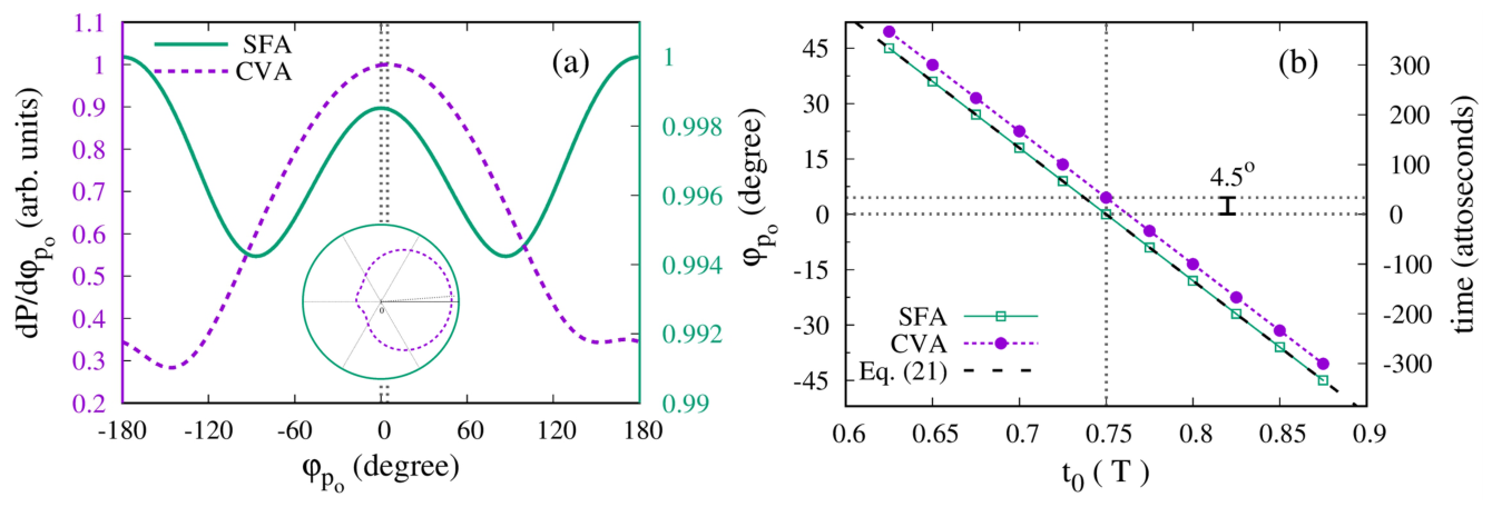
Figure 6(a) shows the resulting angular distributions for and , obtained by radially integrating the PMDs in Figure 5(d,h). The SFA and CVA curves are normalized independently to unity. The inset displays the same distributions in polar coordinates. The SFA distribution is comparatively weakly modulated, although its maximum occurs at the angle predicted by Equation (21). The CVA distribution exhibits a more pronounced maximum near the same direction, together with a small displacement toward larger angles. This difference demonstrates that Coulomb distortion can modify the angular observable even when the overall rotation of the PMD remains intact.
Repeating the radial-integration procedure for several ionization times allows us to determine the angular position of the selected maximum, , as a function of . The results are shown in Figure 6(b), together with the semiclassical prediction of Equation (21). Because the two semiclassical maxima differ by , we follow a single continuous angular branch throughout the IR cycle. The SFA results follow the analytical prediction within the numerical resolution. The CVA results display an approximately systematic angular offset of
As was already mentioned at the outset, for an 800 nm IR field, one degree of angular rotation corresponds to approximately as. Thus, an angular displacement of corresponds to an apparent temporal advance of approximately 34 as under the direct semiclassical angle-to-time conversion Equation (21).
This value should not, however, be interpreted immediately as an intrinsic photoionization delay. Within the CVA, the XUV pulse remains centered at the prescribed time ; the angular displacement arises from the Coulomb distortion of the continuum wave and from the resulting angular dependence of the transition matrix element. In the language of Equation (16), the SFA angular dependence is governed primarily by , whereas in the CVA the prefactor also acquires a nontrivial angular dependence. The extracted 34 as value is therefore best regarded as a Coulomb-induced offset of the clock observable. Establishing its relation to a genuine ionization delay would require a more complete analysis, including direct TDSE calculations for the circularly polarized configuration and a systematic study of the dependence on the field parameters.
The essential LAAC mapping nevertheless survives the inclusion of Coulomb distortion: the PMD rotates with the ionization time, while the Coulomb interaction produces a measurable correction to the angular calibration. This separation between the dominant streaking rotation and the Coulomb-induced angular offset provides a natural basis for future quantitative reconstruction protocols.
4. Conclusions
We have theoretically investigated an attoclock configuration based on laser-assisted photoionization driven by an ultrashort XUV pulse and a circularly polarized IR field. In this laser-assisted attoclock, the XUV pulse defines a localized photoionization window, while the rotating IR vector potential maps the ionization time onto the final photoelectron momentum distribution. The semiclassical model provides a transparent interpretation of this mapping, and its principal predictions are reproduced by the SFA. The comparison with TDSE calculations in the linearly polarized configuration validates the main ring-like streaking structure, while the CVA calculations reveal how the residual Coulomb interaction modifies its angular distribution.
The ionization time is encoded in two closely related features of the PMD. First, in each plane of constant , the LAPE ring is centered at . Its displacement therefore follows the magnitude and direction of the IR vector potential at the time of photoionization. Second, the angular directions of enhanced emission rotate according to the semiclassical relation The displacement and angular rotation are two manifestations of the same underlying vector-potential mapping. The present calculations establish both signatures theoretically, although a dedicated retrieval analysis would be required to determine how they should be combined optimally in an experiment.
The polarization geometry of the fields is crucial for obtaining a clear angular mapping. Choosing the XUV polarization perpendicular to the polarization plane of the circular IR field suppresses the additional azimuthal modulation generated by the photoionization matrix element. The rotation of the ring center is most visible when the magnitude of the IR vector potential is comparable to the radius of the relevant fixed- ring. At the same time, the XUV pulse must be short enough relative to the IR period to isolate a narrow ionization window, but sufficiently long to retain a well-defined carrier frequency and limit spectral broadening. The parameter relations derived in this work provide practical criteria for balancing these requirements.
The CVA calculations preserve the overall rotation and displacement of the PMD, demonstrating that the essential time-to-angle mapping remains present when the Coulomb interaction is included. However, the residual ionic potential generates additional angular asymmetries, redistributes the probability between the semiclassically enhanced directions, and shifts the angular position of the dominant maximum. For the parameters considered here, the CVA produces an offset of approximately , corresponding to about 34 as under the direct semiclassical conversion. This quantity represents a Coulomb-induced correction to the angular clock observable rather than, by itself, a demonstrated intrinsic photoionization delay.
The proposed LAAC combines the controlled temporal localization of XUV photoionization with the angular-streaking capability of a circularly polarized IR field. Unlike conventional attoclock measurements based on tunneling ionization, the emission window is governed directly by the duration and timing of the XUV pulse. The present results establish the theoretical basis for using circularly polarized LAPE as a sub-cycle timing method and motivate further investigations based on full TDSE simulations, finite-pulse effects, Coulomb-corrected retrieval procedures, and extensions to more complex atomic and molecular systems.
Supplementary Materials
The following supporting information can be downloaded at the website of this paper posted on Preprints.org. Two animations show the evolution of the PMDs calculated within the SFA and CVA as the delay is varied continuously. These animations provide a direct visualization of the streaking dynamics and complement the momentum distributions presented in the main text. The animation linear_streaking.mp4 corresponds to the linearly polarized configuration discussed in SubSection 3.1, using the field parameters of Figure 2. The animation attoclock.mp4 corresponds to the LAAC configuration discussed in SubSection 3.2, using the field parameters of Figure 5.
Author Contributions
Conceptualization, R. D. P.; methodology, R. D. P.; software, R. D. P., S. D. L. and D. G. A.; validation, R. D. P. and S. D. L.; formal analysis, S. D. L., J. M. R., M. F. C., D. G. A and R. D. P.; investigation, R. D. P., S. D. L., J. M. R., M. F. C. and D. G. A; resources, R. D. P.; data curation, R. D. P.; writing—original draft preparation, R. D. P., M. F. C., and D. G. A.; visualization, R. D. P., S. D. L and J. M. R.; writing—review and editing, R. D. P, J. M. R., S. D. L., M. F. C. and D. G. A.; supervision, R. D. P.. All authors have read and agreed to the published version of the manuscript.
Funding
M. F. C. acknowledges support by the Quantum Science and Technology-National Science and Technology Major Project (Grant No. 2025ZD0301000), the National Key Research and Development Program of China (Grant No. 2023YFA1407100), the Guangdong Province Science and Technology Major Project (Future functional materials under extreme conditions - 2021B0301030005) and the National Natural Science Foundation of China (Grant No. 12574092). D. G. A. acknowledges support by Agencia I+D+i (Argentina) grant numbers PICT 2020-01755 and 2020-01434 and Consejo Nacional de Investigaciones Científicas y Técnicas (CONICET) (Argentina) grant number PIP 2022-2024 11220210100468CO. S. D. L. acknowledges support by Programa Nacional RAICES Federal: Edición 2022 of Ministerio de Ciencia, Tecnología e Innovación (MinCyT), PICT 2023 RAÍCES FEDERAL 01-PICT-2023-02-10 from Agencia I+D+i (Argentina) and grant number PIP Raices 2023-2025 29320230100003CO of CONICET (Argentina). R. D. P., J. M. R. and S. D. L. acknowledge support by the National University of Cuyo (Grant No: 80020240100520UN, 2025–2027) Argentina.
Data Availability Statement
The data that support the findings of this study are available from the corresponding author upon reasonable request.
Conflicts of Interest
The authors declare no conflicts of interest.
References
- Hentschel, M.; Kienberger, R.; Spielmann, C.; Reider, G.A.; Milosevic, N.; Brabec, T.; Corkum, P.; Heinzmann, U.; Drescher, M.; Krausz, F. Attosecond metrology. Nature 2001, 414, 509–513. [Google Scholar] [CrossRef] [PubMed]
- Itatani, J.; Quéré, F.; Yudin, G.L.; Ivanov, M.Y.; Krausz, F.; Corkum, P.B. Attosecond streak camera. Phys. Rev. Lett. 2002, 88, 173903. [Google Scholar] [CrossRef] [PubMed]
- Kienberger, R.; Goulielmakis, E.; Uiberacker, M.; Baltuška, A.; Yakovlev, V.; Bammer, F.; Scrinzi, A.; Westerwalbesloh, T.; Kleineberg, U.; Heinzmann, U.; et al. Atomic transient recorder. Nature 2004, 427, 817–821. [Google Scholar] [CrossRef] [PubMed]
- Cavalieri, A.L.; Müller, N.; Uphues, T.; Yakovlev, V.S.; Baltuška, A.; Horvath, B.; Schmidt, B.; Blümel, L.; Holzwarth, R.; Hendel, S.; et al. Attosecond spectroscopy in condensed matter. Nature 2007, 449, 1029–1032. [Google Scholar] [CrossRef] [PubMed]
- Schultze, M.; Fiess, M.; Karpowicz, N.; Gagnon, J.; Korbman, M.; Hofstetter, M.; Neppl, S.; Cavalieri, A.L.; Komninos, Y.; Mercouris, T.; et al. Delay in photoemission. Science 2010, 328, 1658–1662. [Google Scholar] [CrossRef] [PubMed]
- Nagele, S.; Pazourek, R.; Feist, J.; Doblhoff-Dier, K.; Lemell, C.; Tokési, K.; Burgdörfer, J. Time-resolved photoemission by attosecond streaking: extraction of time information. J. Phys. B At. Mol. Opt. Phys. 2011, 44, 081001. [Google Scholar] [CrossRef]
- Eckle, P.; Smolarski, M.; Schlup, P.; Biegert, J.; Staudte, A.; Schöffler, M.; Muller, H.G.; Dörner, R.; Keller, U. Attosecond angular streaking. Nat. Phys. 2008, 4, 565–570. [Google Scholar] [CrossRef]
- Eckle, P.; Pfeiffer, A.N.; Cirelli, C.; Staudte, A.; Dörner, R.; Muller, H.G.; Büttiker, M.; Keller, U. Attosecond ionization and tunneling delay time measurements in helium. Science 2008, 322, 1525–1529. [Google Scholar] [CrossRef]
- Pfeiffer, A.N.; Cirelli, C.; Smolarski, M.; Dörner, R.; Keller, U. Timing the release in sequential double ionization. Nat. Phys. 2011, 7, 428–433. [Google Scholar] [CrossRef]
- Landsman, A.S.; Weger, M.; Maurer, J.; Boge, R.; Ludwig, A.; Heuser, S.; Cirelli, C.; Gallmann, L.; Keller, U. Ultrafast resolution of tunneling delay time. Optica 2014, 1, 343–349. [Google Scholar] [CrossRef]
- Torlina, L.; Morales, F.; Kaushal, J.; Ivanov, I.; Kheifets, A.; Zielinski, A.; Scrinzi, A.; Müller, H.G.; Sukiasyan, S.; Ivanov, M. Interpreting attoclock measurements of tunnelling times. Nat. Phys. 2015, 11, 503–508. [Google Scholar] [CrossRef]
- Hofmann, C.; Landsman, A.S.; Keller, U. Attoclock revisited on electron tunnelling time. J. Mod. Opt. 2019, 66, 1052–1070. [Google Scholar] [CrossRef]
- Kheifets, A.S. The attoclock and the tunnelling time debate. J. Phys. B At. Mol. Opt. Phys. 2020, 53, 072001. [Google Scholar] [CrossRef]
- Maquet, A.; Taïeb, R. Two-colour IR+XUV spectroscopies: the soft-photon approximation. J. Mod. Opt. 2007, 54, 1847–1857. [Google Scholar] [CrossRef]
- Miaja-Avila, L.; Saathoff, G.; Aeschlimann, M.; Murnane, M.M.; Kapteyn, H.C. Laser-assisted photoelectric effect from surfaces. Phys. Rev. Lett. 2006, 97, 113604. [Google Scholar] [CrossRef] [PubMed]
- Chini, M.; Gilbertson, S.; Khan, S.D.; Chang, Z. Characterizing ultrabroadband attosecond lasers. Opt. Express 2010, 18, 13006–13016. [Google Scholar] [CrossRef] [PubMed]
- Arbó, D.G.; Ishikawa, K.L.; Schiessl, K.; Persson, E.; Burgdörfer, J. Intracycle and intercycle interferences in above-threshold ionization: The time grating. Phys. Rev. A 2010, 81, 021403. [Google Scholar] [CrossRef]
- Gramajo, A.A.; Della Picca, R.; López, S.D.; Arbó, D.G. Intra- and intercycle interference of angle-resolved electron emission in laser-assisted XUV atomic ionization. J. Phys. B At. Mol. Opt. Phys. 2018, 51, 055603. [Google Scholar] [CrossRef]
- Della Picca, R.; Ciappina, M.F.; Lewenstein, M.; Arbó, D.G. Laser-assisted photoionization: Streaking, sideband, and pulse-train cases. Phys. Rev. A 2020, 102, 043106. [Google Scholar] [CrossRef]
- Gramajo, A.A.; Della Picca, R.; Garibotti, C.R.; Arbó, D.G. Laser-assisted photoionization of hydrogen by attosecond pulse trains. Phys. Rev. A 2016, 94, 053404. [Google Scholar] [CrossRef]
- Della Picca, R.; Randazzo, J.M.; López, S.D.; Ciappina, M.F.; Arbó, D.G. Laser-assisted photoionization beyond the dipole approximation. Phys. Rev. A 2023, 107, 053104. [Google Scholar] [CrossRef]
- Della Picca, R.; Randazzo, J.M.; López, S.D.; Ciappina, M.F.; Arbó, D.G. Nondipole circularly polarized laser-assisted photoelectron emission. Phys. Rev. A 2025, 112, 023111. [Google Scholar] [CrossRef]
- Zhao, Z.X.; Chang, Z.; Tong, X.M.; Lin, C.D. Circularly-polarized laser-assisted photoionization spectra for attosecond pulse measurements. Opt. Express 2005, 13, 1966–1977. [Google Scholar] [CrossRef] [PubMed]
- Della Picca, R.; Randazzo, J.M.; López, S.D.; Ciappina, M.F.; Arbó, D.G. Nondipole circularly polarized laser-assisted photoelectron emission. Phys. Rev. A 2025, 112, 023111. [Google Scholar] [CrossRef]
- Macri, P.A.; Miraglia, J.E.; Gravielle, M.S. Ionization of hydrogen targets by short laser pulses. J. Opt. Soc. Am. B 2003, 20, 1801–1806. [Google Scholar] [CrossRef]
- Rodríguez, V.D.; Cormier, E.; Gayet, R. Ionization by short uv laser pulses: Secondary above-threshold-ion ization peaks of the electron spectrum investigated through a modified Coulomb-V olkov approach. Phys. Rev. A 2004, 69, 053402. [Google Scholar] [CrossRef]
- Arbó, D.G.; Miraglia, J.E.; Gravielle, M.S.; Schiessl, K.; Persson, E.; Burgdörfer, J. Coulomb-Volkov approximation for near-threshold ionization by shor t laser pulses. Phys. Rev. A 2008, 77, 013401. [Google Scholar] [CrossRef]
- Della Picca, R.; Fiol, J.; Fainstein, P.D. Factorization of laser–pulse ionization probabilities in the multiphotonic regime. J. Phys. B At. Mol. Opt. Phys. 2013, 46, 175603. [Google Scholar] [CrossRef]
- Migliaro, C.; Randazzo, J.M.; Della Picca, R. Strong-Field Photoionization: Analysis of Overlapping Above-Threshold Ionization and Laser-Assisted Photoemission Structures. Phys. Sci. Forum 2026, 13. [Google Scholar] [CrossRef]
- Arbó, D.G.; Yoshida, S.; Persson, E.; Dimitriou, K.I.; Burgdörfer, J. Interference Oscillations in the Angular Distribution of Laser-Ionized Electrons near Ionization Threshold. Phys. Rev. Lett. 2006, 96, 143003. [Google Scholar] [CrossRef] [PubMed]
- Arbó, D.G.; Dimitriou, K.I.; Persson, E.; Burgdörfer, J. Sub-Poissonian angular momentum distribution near threshold in atomic ionization by short laser pulses. Phys. Rev. A 2008, 78, 013406. [Google Scholar] [CrossRef]
Figure 1.
Schematic representation of the SCM PMD sphere in momentum space for three different ionization times (black), (red) and (blue). (a) Case of linear polarization along in the plane. (b) Circular polarization case in the plane.
Figure 1.
Schematic representation of the SCM PMD sphere in momentum space for three different ionization times (black), (red) and (blue). (a) Case of linear polarization along in the plane. (b) Circular polarization case in the plane.
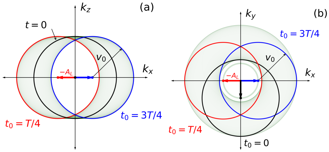
Figure 2.
PMDs for H() in the plane calculated using the TDSE [panels (a)–(d)], the CVA [panels (e)–(h)], and the SFA [panels (i)–(l)]. The ionization times are in panels (a), (e), and (i); in panels (b), (f), and (j); in panels (c), (g), and (k); and in panels (d), (h), and (l). The arrows indicate . The black circles, with radius a.u. and centers located at , represent the solutions of the saddle-point equation Equation (14). Here, ; the remaining field parameters are given in the text. The color scales are given in arbitrary units.
Figure 2.
PMDs for H() in the plane calculated using the TDSE [panels (a)–(d)], the CVA [panels (e)–(h)], and the SFA [panels (i)–(l)]. The ionization times are in panels (a), (e), and (i); in panels (b), (f), and (j); in panels (c), (g), and (k); and in panels (d), (h), and (l). The arrows indicate . The black circles, with radius a.u. and centers located at , represent the solutions of the saddle-point equation Equation (14). Here, ; the remaining field parameters are given in the text. The color scales are given in arbitrary units.
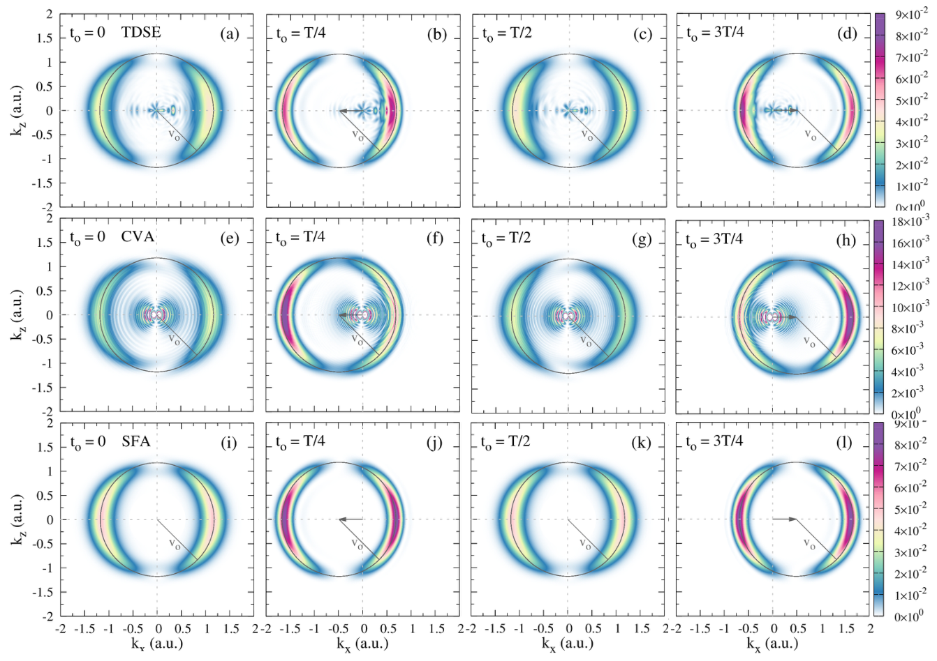
Figure 3.
SFA PMDs for H() in the plane at . Panels (a) and (b) correspond to , with and , respectively. Panel (c) shows the results for and six values , with . The remaining field parameters are the same as in Figure 2. The black arrows indicate , and the blue arrow in panel (c) denotes the XUV polarization direction.
Figure 3.
SFA PMDs for H() in the plane at . Panels (a) and (b) correspond to , with and , respectively. Panel (c) shows the results for and six values , with . The remaining field parameters are the same as in Figure 2. The black arrows indicate , and the blue arrow in panel (c) denotes the XUV polarization direction.
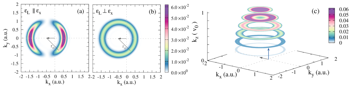
Figure 4.
SFA PMDs for H() in the plane at , obtained using a circularly polarized IR field. The XUV field is polarized along , perpendicular to the IR polarization plane. The ionization time is indicated in each panel, and the eight values shown span one complete IR period. The remaining field parameters are the same as in Figure 3(b). The black arrows indicate . The black circle in the first panel shows the SCM prediction for .
Figure 4.
SFA PMDs for H() in the plane at , obtained using a circularly polarized IR field. The XUV field is polarized along , perpendicular to the IR polarization plane. The ionization time is indicated in each panel, and the eight values shown span one complete IR period. The remaining field parameters are the same as in Figure 3(b). The black arrows indicate . The black circle in the first panel shows the SCM prediction for .
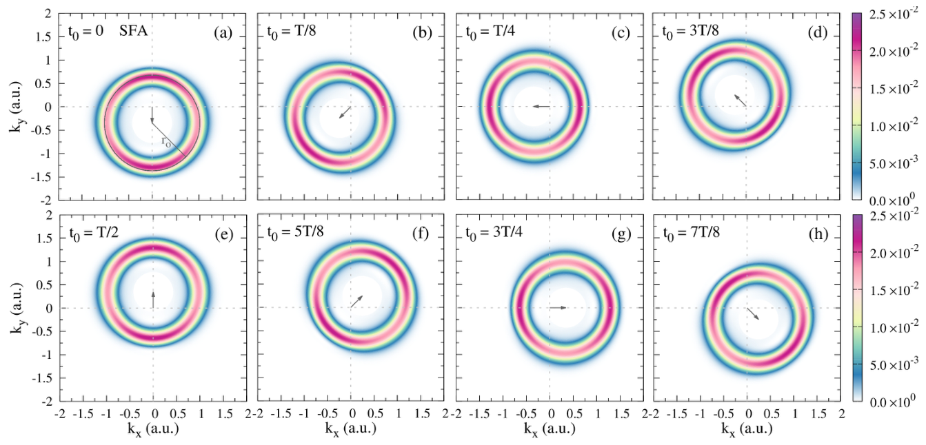
Figure 5.
Superimposed PMDs for H() in the plane for , producing the localized central contribution, and , producing the ring-like structure of radius . The ionization time is indicated in each panel. Panels (a)–(d) show the SFA results, and panels (e)–(h) show the corresponding CVA results. The field parameters are a.u., , and ; the remaining parameters are the same as in Figure 4. The gray arrows indicate .
Figure 5.
Superimposed PMDs for H() in the plane for , producing the localized central contribution, and , producing the ring-like structure of radius . The ionization time is indicated in each panel. Panels (a)–(d) show the SFA results, and panels (e)–(h) show the corresponding CVA results. The field parameters are a.u., , and ; the remaining parameters are the same as in Figure 4. The gray arrows indicate .
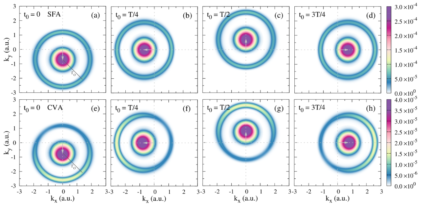
Figure 6.
(a) Normalized, radially integrated ring contributions obtained from Figure 5 for and , plotted as functions of . The green solid curve shows the SFA result, and the purple dashed curve shows the CVA result. The inset presents the same distributions in polar coordinates. (b) Angular positions of the selected PMD maximum as functions of . Green squares connected by a solid line show the SFA results, purple circles connected by a dashed line show the CVA results, and the black dashed line gives the semiclassical prediction of Equation (21). A single continuous angular branch is shown; the second branch is displaced by .
Figure 6.
(a) Normalized, radially integrated ring contributions obtained from Figure 5 for and , plotted as functions of . The green solid curve shows the SFA result, and the purple dashed curve shows the CVA result. The inset presents the same distributions in polar coordinates. (b) Angular positions of the selected PMD maximum as functions of . Green squares connected by a solid line show the SFA results, purple circles connected by a dashed line show the CVA results, and the black dashed line gives the semiclassical prediction of Equation (21). A single continuous angular branch is shown; the second branch is displaced by .
Disclaimer/Publisher’s Note: The statements, opinions and data contained in all publications are solely those of the individual author(s) and contributor(s) and not of MDPI and/or the editor(s). MDPI and/or the editor(s) disclaim responsibility for any injury to people or property resulting from any ideas, methods, instructions or products referred to in the content. |
© 2026 by the authors. Licensee MDPI, Basel, Switzerland. This article is an open access article distributed under the terms and conditions of the Creative Commons Attribution (CC BY) license (http://creativecommons.org/licenses/by/4.0/).
Copyright: This open access article is published under a Creative Commons CC BY 4.0 license, which permit the free download, distribution, and reuse, provided that the author and preprint are cited in any reuse.