

Submitted:
06 August 2026
Posted:
07 August 2026
You are already at the latest version
Abstract
Fiber-Reinforced Polymers (FRPs) are increasingly adopted in structural rehabilitation due to their high strength-to-weight ratio, corrosion resistance, and ease of installation, making them suitable for extending the service life of reinforced concrete (RC) infrastructure. Studies on shear strengthening with CFRP was early focused on externally boning (EB) showed premature delamination between fiber and concrete which limits the bonding strength. Hence, This study experimentally evaluates the shear strengthening behavior of RC beams retrofitted using inside-groove bonded CFRP and hybrid techniques. A total of eight beam specimens with identical geometry, internal reinforcement layout, and concrete strength were fabricated and tested under four-point bending to generate a well-defined shear-critical region. The experimental program focused on directly comparing bonding configurations while also examining the influence of groove depth (10 mm and 15 mm) and steel anchorage detailing on structural response and failure mechanisms. The strengthened specimens achieved ultimate load increases ranging from approximately 10% to 23% relative to the control beam. Variation in groove depth within the investigated range did not significantly influence shear capacity, indicating that moderate groove penetration is sufficient to develop effective mechanical interlock. Steel anchors were introduced to restrain concrete cover separation and improve confinement of the bonded region. While anchorage did not substantially increase peak load, it successfully mitigated premature cover delamination near stirrup locations and altered the governing failure mode.
Keywords:
strengthening
; CFRP composite
; inside groove
; over groove
; hybrid
1. Introduction
Fiber-Reinforced Polymer (FRP) composites have become increasingly important in civil engineering because of their high tensile strength, corrosion resistance, and low self-weight. The application have been conducted fo different concrete structures [1,2,3,4], steel structures [5,6] and masonary [7,8].
Despite significant progress in the development of Fiber-Reinforced Polymer (FRP) strengthening systems, practical challenges remain in their application to shear-critical reinforced concrete (RC) members [9,10]. While FRP materials have demonstrated clear benefits in improving flexural capacity and durability, their performance in shear strengthening is often governed by brittle behavior and premature debonding at the concrete interface [11,12]. When debonding occurs before the FRP reaches its tensile limit, the strengthening system cannot deliver its intended contribution, reducing overall effectiveness. To address this limitation, the anchorage system using surface grooving techniques such as NSM [13,14,15], Externally Bonded Reinforcement on Groove (EBROG) and Externally Bonded Reinforcement in Groove (EBRIG) have been introduced as methods for enhancing bond performance and delaying premature failure [16,17,18,19,20]. These approaches increase mechanical interlock between FRP and concrete, promoting improved stress transfer and more reliable shear resistance [21,22]. However, the existing literature contains limited comparative investigations that evaluate EBROG and EBRIG under consistent experimental conditions while also considering variations in FRP reinforcement layouts, including single-layer, double-layer, and hybrid laminate–fabric systems [23,24]. Without such comparisons, it remains difficult to identify the most effective strengthening strategy in terms of bond behavior and load capacity. In addition, only a small number of studies examine how layered FRP configurations influence structural efficiency in shear-dominated regions, where vertical stress concentrations are critical [25]. As a result, a clear understanding of how grooving techniques interact with reinforcement layering is still lacking. The absence of unified design principles for groove-based FRP shear strengthening further limits the practical adoption of these methods in rehabilitation projects. However, most studies on grooving system have been conducted for longitudinal grooves [26,27], and limited application transverse grooves configuration has been applied only for flexural strengthening [28,29]
To address these gaps, this study experimentally investigates the shear behavior of RC beams strengthened using EBROG and EBRIG and hybrid techniques with varying FRP reinforcement in transverse configurations under two-point loading. Key performance indicators, including ultimate shear capacity, bond integrity, and failure mechanisms, are evaluated through a comparative framework intended to support engineering decision-making. By examining the combined effects of groove geometry and reinforcement layering, the research contributes new experimental evidence that can inform performance-based strengthening guidelines.
2. Experimental Program
2.1. Tested Specimens
The program describes the experimental methodology used to investigate the shear strengthening of reinforced concrete (RC) beams using fiber-reinforced polymer (FRP) systems combined with surface grooving techniques. Eight reinforced concrete beam specimens, labelled RB1and B2 through B7, were fabricated for the experimental program. All beams shared identical geometric dimensions of 200 mm width, 300 mm overall depth, and 1800 mm length as shown in Figure 2-1 and Figure 2-3. The concrete mix was designed to achieve a target compressive strength of 35 MPa. The only variable among specimens was the strengthening configuration, allowing a direct comparison of the effects of different retrofit techniques.
Specimen RB1 served as the reference control beam and was tested without any FRP strengthening or surface grooving.
Specimen B2 was strengthened using a single fabric layer applied without grooves. The reinforcement was installed using conventional externally bonded surface strengthening with MapeWrap 31 adhesive. Six CFRP strips were placed within the shear region at a spacing of 70 mm.
Specimen B3 was strengthened with EBROG technique. One layer of CFRP fabric was laid over the grooves after filling them with the adhesive.
Specimens B4 and B5 were strengthened using the EBRIG technique with fabric fiber reinforcement. Each beam received a single embedded fabric layer in different groove depths of 10 mm for B4 and 15 mm for B5 to assess repeatability and consistency of the strengthening approach.
Specimens B6 was retrofitted with a hybrid double-layer fabric and laminate reinforcement system. The fabric layer was embedded within grooves using the EBRIG technique and bonded with MapeWrap 31. A laminate CFRP layer was then installed externally using the EBR method and bonded with Adesilex PG2 TG adhesive.
Specimens B7 employed a hybrid strengthening scheme similar to B6 and provided with anchorage of concrete cover at sides of the beams using steel bars (10 mm diameter) penetrated inside holes of 12 mm diameter and 100 mm in depth. Six anchors at each side of strengthened part of the beam distributed under the bonding area. The bars were inserted after filling the holes with epoxy. The specimen’s details are illustrated in Table 2-1.
Figure 2-1.
Geometry and dimensions of RC beam.
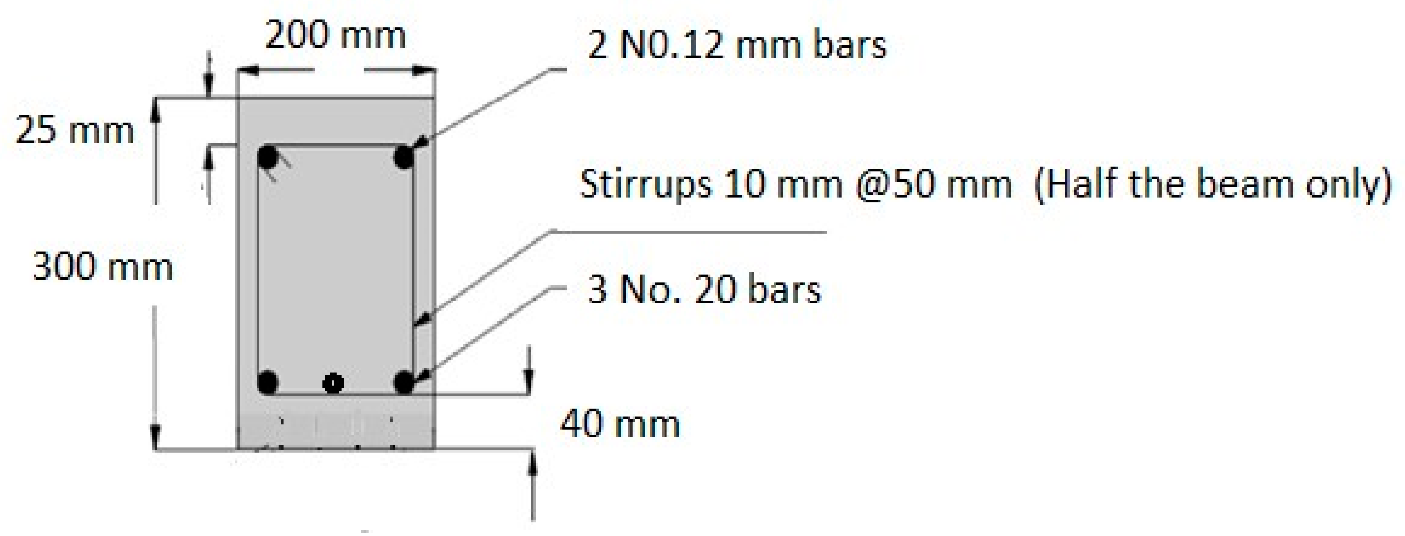
Figure 2-2.
Elevation and dimensions of RC beam.
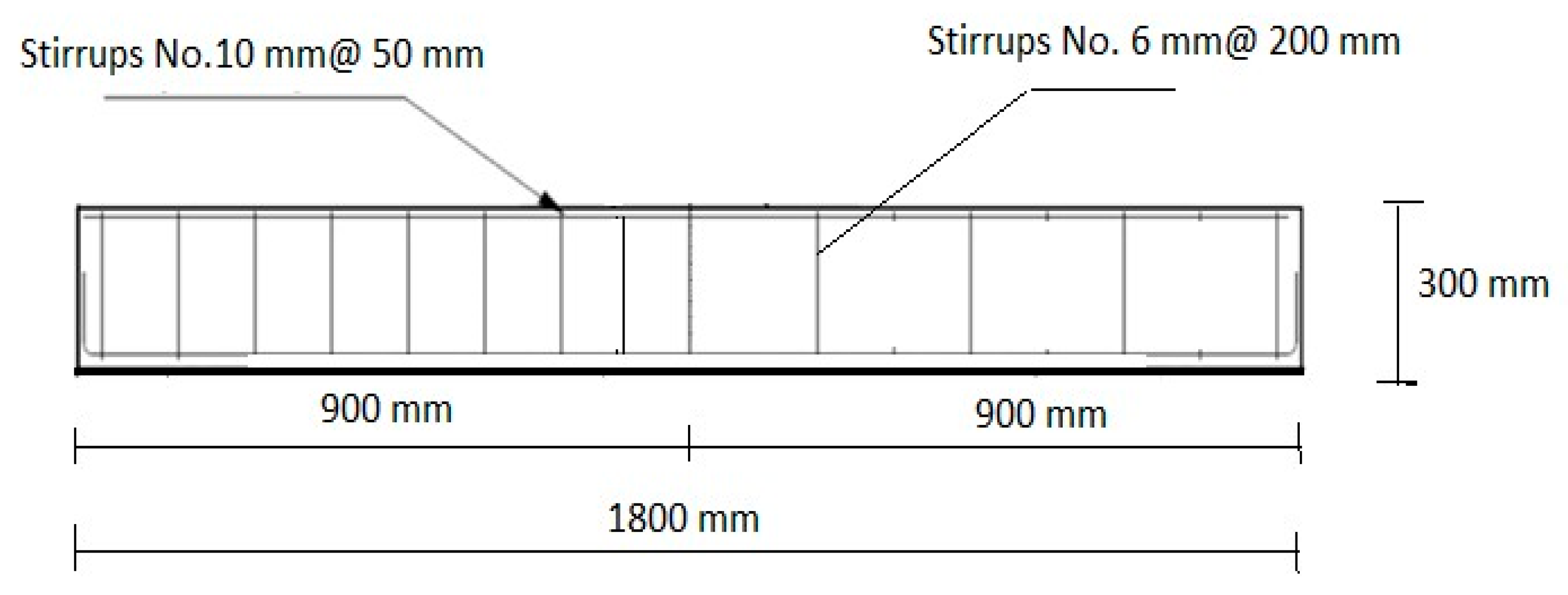

Table 2-1.
Details of the tested beams.
| Beam No. | Designation | Strengthening Type | Groove Depth (mm) |
Groove Width (mm) |
Groove Spacing (mm) |
|---|---|---|---|---|---|
| RB1 | Control Beam | No strengthening | — | — | — |
| B2 | EB-1L-F | Single-layer fabric | — | — | — |
| B3 | OG-10D-1L-F | EBROG fabric | 10 | 5 | 70 |
| B4 | IG-10D-1L-F | EBRIG fabric | 15 | 5 | 70 |
| B5 | IG-15D-1L-F | EBRIG fabric | 10 | 5 | 70 |
| B6 | HS-D15-2LF&L | Double-layer hybrid | 15 | 5 | 70 |
| B7 | HS-D15-2LF&L (Anchored) | Double-layer hybrid (Anchored) | 15 | 5 | 70 |
EB: Externaly bonding, OG: Over groove, IG: Inside groove, HS: Hybrid system, D: Depth of groove, 1L: one layer of CFRP, F&L: Fabric and Laminate CFRP.
2.2. Materials Properties
2.2.1. Concrete Mix Characteristics
A pre-mixed cementitious concrete was used for casting all beam specimens. The mix design targeted a compressive strength of 35 MPa. Standard laboratory testing was performed to characterize the mechanical properties of the concrete prior to beam testing.
2.2.2. Reinforcement Characterises
Longitudinal reinforcement was provided using high-tensile steel (HTS) bars conforming to Grade 60 specifications, with a nominal yield strength of 420 MPa. Bar diameters of 10 mm and 12 mm were used depending on the reinforcement requirements of each specimen. The longitudinal steel was designed to resist flexural tensile stresses and to ensure that failure would be governed by shear rather than bending.
2.2.3. CFRP Materials
Carbon fiber reinforced polymer (CFRP) materials were used as external shear reinforcement in the experimental program. Two CFRP systems were employed: unidirectional fabric sheets and prefabricated laminate strips. The CFRP fabric consisted of lightweight unidirectional carbon fiber sheets designed specifically for surface-applied reinforcement. Its flexibility allowed it to conform effectively to the beam surface and to the geometry of the prepared grooves. The mechanical properties of the fabric and laminate were obtained from the manufacturer’s technical datasheet and are summarized in Table 2-2 and Table 2-3 respectively.
2.3. Fabrication of Tested RC Beams
All beam specimens were fabricated under controlled laboratory conditions to ensure consistency, accuracy, and repeatability across the experimental program. The fabrication process included reinforcement assembly, concrete casting, curing, surface preparation, and installation of the CFRP strengthening systems. Each stage of the specimen preparation is described in the following subsections.
2.3.1. Reinforcement Detailing
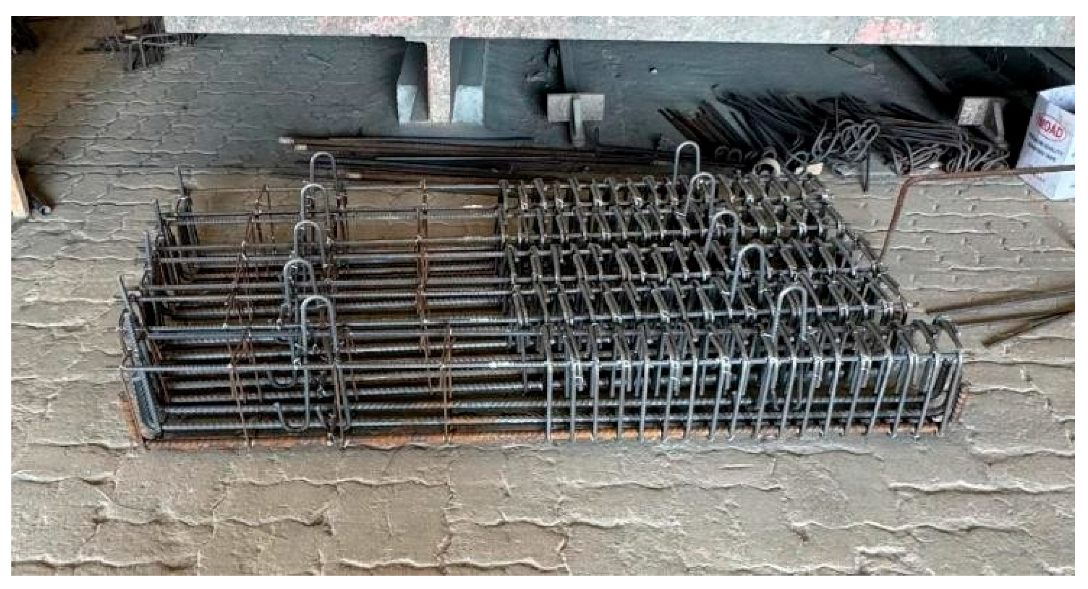
Reinforcement cages were assembled in accordance with the design drawings using high-tensile steel bars. Longitudinal bars and stirrups were carefully positioned and secured to maintain the specified spacing and alignment prior to concrete casting. Figure 2-3 illustrates the reinforcement detailing before concrete placement.
Figure 2-3.
Reinforcement cage detailing prior to concrete casting.
2.3.2. Beam Casting
Concrete was poured into the prepared molds in successive layers and mechanically vibrated to achieve proper compaction and eliminate entrapped air. Care was taken to prevent segregation and to ensure uniform distribution of the concrete along the beam length. After casting, the beam surfaces were finished and protected to support proper curing. Figure 2-4 shows the casting process of the reinforced concrete beam specimens.
2.3.3. Curing and Demolding
After casting, the beam specimens were removed from the molds and stored under controlled curing conditions. The beams were protected against moisture loss and allowed to cure for 28 days to reach the target concrete strength. Proper curing ensured uniform mechanical properties across all specimens prior to strengthening.
2.3.4. Surface Preparation and Grooving
After curing, the beam surfaces were prepared for strengthening by marking the designated shear regions and laying out the groove pattern according to the strengthening configuration. A reference grid was drawn to maintain consistent spacing of the CFRP strips. Grooves were then cut using a mechanical grinder to create the required profile and enhance mechanical interlock between the CFRP reinforcement and the concrete substrate. Figure 2-5 illustrate the marking and grooving process.
2.3.5. CFRP Installation
Following surface preparation, the beam surfaces were carefully cleaned to remove dust, debris, and loose particles. Epoxy adhesive was applied within the grooves and over the surrounding concrete surface. The CFRP strips were then positioned according to the strengthening layout and pressed firmly into place to ensure full contact with the adhesive. Where specified, steel rods were embedded inside the grooves to provide additional mechanical anchorage. A final epoxy layer was applied to fully encapsulate the reinforcement and eliminate trapped air voids. Figure 2-6 illustrates the CFRP bonding sequence.
2.4. Instrumentation
The experimental tests were performed using an Instron 8806 servo-hydraulic testing machine, shown in Figure 2-7. The system is capable of applying high-capacity static loads with precise displacement control, making it well suited for structural testing of reinforced concrete beams. Load from the actuator was transferred to the specimen through a steel loading plate measuring 300 × 600 × 20 mm to ensure uniform load distribution.
The beam specimens were supported on steel bearing plates measuring 100 × 200 × 12.5 mm. One support was configured as a roller, while the opposite support acted as a hinge, creating a simply supported boundary condition.
Mid-span deflection was recorded using a Linear Variable Differential Transformer (LVDT) with an accuracy of 0.001 mm. The LVDT was positioned beneath the beam at the location of maximum expected deflection. Concrete strain was measured using electrical resistance strain gauges manufactured by Tokyo Measuring Instruments Laboratory Co., Ltd. (TML). The installed gauges were model PL-60-11-5LJC-F and were placed at selected locations to capture strain distribution during loading, as illustrated in Figure 2-8.
2.5. Test Procedure
All beam specimens were tested under static loading using a four-point bending configuration designed to promote shear-dominated behavior. Testing was performed when the specimens reached 28 days of age. The four-point loading arrangement created a defined shear region between the support and loading points while maintaining a constant moment region at midspan.
Load was applied incrementally in 10 kN steps under displacement control at a rate of 0.8 mm/min. Each specimen was subjected to progressive cyclic loading with at least four intermediate load levels to monitor structural response. Loading proceeded continuously until global failure occurred.
During testing, deflection and strain were recorded continuously using the LVDT and electrical strain gauges described in Section 3.5. Crack formation, debonding behavior, and failure mechanisms were visually monitored and documented throughout the loading process.
3. Results and Discussion
RB1 Specimen
The control beam RB1 failed at an ultimate load of 380.48 kN, corresponding to a maximum midspan deflection of 10.428 mm. Failure was governed by the formation of a sudden diagonal shear crack that initiated near the support and propagated toward the loading region (see Figure 3-9). The observed crack pattern is characteristic of brittle shear failure in beams without external strengthening. No significant flexural crushing was detected at midspan prior to collapse. The abrupt nature of failure confirms that the specimen behaved as a shear-critical member.
B2 Specimen
The strengthened specimen B2 demonstrated an increased load-carrying capacity compared with the reference beam RB1, while exhibiting a similar elastic response during the initial loading stage. The ultimate load of specimen B2 reached 421.721 kN, compared with 380.48 kN for RB1, representing an improvement of 10.83%. This enhancement is attributed to the externally bonded CFRP strengthening system, which increased shear resistance by limiting crack opening and contributing to stress transfer across the shear-critical region. A comparison of the load–displacement responses of RB1, B2 and B3 is presented in Figure 3-10.
The observed cracking pattern indicates that failure was governed by a dominant diagonal shear crack extending through the shear span toward the loading point, accompanied by fiber delamination due to localized concrete spalling near the critical crack zone. the failure pattern of specimen B2 is illustrated in Figure 3-11.
Specimen B3 strengthened with EBOTG achieved ultimate load capacity of 423.23 kN. The load displacement curve is illustrated in Figure 3-10. The conventional mode of failure was the delamination of the CFRP by spalling of concrete under the fiber as shown in Figure 3-12.
B4 and B5 Specimens
Specimens B4, and B5, strengthened using the IG-10D-1L-F configuration, exhibited a consistent increase in shear capacity relative to the control beam RB1. The recorded ultimate loads were 428.00 kN, 428.11 kNcorresponding to improvements of 12.49%, 12.52% respectively. The close agreement among these values demonstrates strong repeatability of the strengthening method. Their load–displacement curves were nearly identical, indicating stable bond behavior and uniform stress transfer within the grooved region as shown in Figure 3-13.
All three specimens failed in a similar manner, governed by shear rupture of the CFRP reinforcement and spalling of concrete near the shear cracks as shown in Figure 3-14 and Figure 3-15. This failure mode confirms that the fibers were effectively engaged and carried tensile stresses up to their capacity prior to collapse. The results suggest efficient interaction between the CFRP and concrete substrate, with the groove-assisted anchorage enabling full mobilization of the strengthening system.
B6 and B7 Specimens
Specimens B6 and B7, strengthened using hybrid reinforcement layouts, Specimen B6, which incorporated a hybrid fabric–laminate system, achieved the maximum recorded capacity of 438.08 kN, representing a 15.28% increase compared with RB1 and a 45% over the increase in B2. B7 with anchorage of concrete cover demonstrated the highest structural capacity among all tested beams providing thee higher load capacity of 467.8 kN achieving an increase of about 23% in comparison with RB and 50% over the increase in B6. Figure shows the load –displacement behavior of B6 and B7 compared with RB1 and B2 as illustrated in Figure 3-16.
In specimens B6, failure occurred due to separation of the concrete cover, indicating that the concrete substrate governed the ultimate response (see Figure 3-17), while the delamunation of CFRP was the failure mode of B7, indicating that the bond between the CFRP hybrid system governed the ultimate load capacity (see Figure 3-18). The separation of cover suggests that the strengthening system was highly engaged prior to failure, allowing significant stress redistribution before debonding initiated. The inclusion Steel anchors was introduced to restrain concrete cover separation and improve confinement of the bonded region and altered the failure mechanism toward the contribution of hybrid strengthening.to significantly increases the ultimate load capacit. The test results are reported in Table 3-3.
Table 3-3.
Test results and mode of failure of the specimens.
| Beam No. |
Designation | Groove Depth (mm) | Groove Width (m7m) |
Distance Between Grooves (mm) |
Ultimate Load (kN) |
Failure Mode |
|---|---|---|---|---|---|---|
| RB | Control Beam | – | – | – | 380.48 | Diagonal shear crack |
| B2 | EB-1L-F | – | – | – | 420 | Diagonal shear crack (delamination of fiber |
| B3 | OG-10D-1L-F | 10 | 5 | 70 | 423.23 | Shear Failure in Concrete (delamination of fiber |
| B4 | IG-10D-1L-F | 10 | 5 | 70 | 428 | Shear Crack (Rupture of fiber) |
| B5 | IG-15D-1L-F | 15 | 5 | 70 | 428.11 | CFRP rupture in shear (Rupture of fiber) |
| B6 | HS-D15-2LF&L | 15 | 5 | 70 | 438.08 | Shear Failure in Concrete (Separation of concrete cover) |
| B7 | HS-D15-2LF&L(Anchored) | 15 | 5 | 70 | 467.8 | Shear Failure in Concrete accompanied with delamination of CFRP and spalling of concrete under bonding area |
EB: Externally bonding, OG: Over groove, IG: Inside groove, HS: Hybrid system, D: Depth of groove, 1L: one layer of CFRP, F&L: Fabric and Laminate CFRP.
4. Conclusion
This study experimentally evaluated the shear strengthening performance of reinforced concrete beams strengthened using externally bonded CFRP and inside-groove bonded CFRP techniques. The investigation focused on the influence of bonding configuration, groove depth (10 mm and 15 mm), and steel anchorage detailing on ultimate load capacity and governing failure mechanisms.
The control beam failed at an ultimate load of 380.48 kN with brittle diagonal shear cracking. Externally bonded strengthening increased the load capacity to approximately 420–428 kN, corresponding to an improvement of about 10.8% relative to the control specimen. The inside-groove bonded specimens exhibited comparable or slightly improved performance, with ultimate load increases within a similar range of approximately 12.5%. The structural responses were highly repeatable across specimens, confirming consistency of the strengthening technique.
The variation in groove depth between 10 mm and 15 mm did not produce a significant change in ultimate load capacity, indicating that within the investigated range, groove depth was not a dominant factor influencing shear strength enhancement. This suggests that moderate groove depths are sufficient to achieve effective mechanical interlock without requiring excessive concrete removal.
The load–displacement responses indicate that hybrid strengthening provided both higher ultimate strength (438.08 kN) and enhanced capacity about 15.28% . This behavior is attributed to improved confinement and more efficient shear stress transfer resulting from the multilayer strengthening configuration.
Steel anchors were introduced to restrain concrete cover separation and improve confinement of the bonded region. significantly increase ultimate load capacity, and altered the failure mechanism. The recorded ultimate capacity was (467.8 kN) provided an increase of about 50% over the B6. In non-anchored specimens, preliminary distress occurred in the form of concrete cover separation near stirrup locations due to stress concentration beneath the bonded CFRP layer. When steel anchors were used, cover delamination was effectively restrained, and failure shifted toward concrete-controlled diagonal shear cracking accompanied with s delamination of CFRP system with spalling of concrete under bonding area. This confirms that anchorage contributed primarily to stabilizing the failure mode rather than directly enhancing peak load.
In several strengthened beams, failure was governed by concrete crushing or shear cracking rather than fiber rupture, indicating that the strengthening system approached the capacity of the concrete substrate. This suggests that further increases in shear capacity could potentially be achieved if higher concrete compressive strength or improved confinement were provided, allowing fuller mobilization of CFRP tensile capacity.
Author Contributions
Conceptualization, Ahmed H. Al-Abdwais; Methodology, Ahmed H. Al-Abdwais and Mahir Al-Hamad; Validation, Ahmed H. Al-Abdwais and Adil K. Al-Tamimi; Formal analysis, Ahmed H. Al-Abdwais and Mahir Al-Hamad; Resources, Ahmed H. Al-Abdwais; Writing—original draft, Mahir Al-Hamad; Writing—review & editing, Ahmed Al-Abdwais and Adil K. Al-Tamimi; Funding acquisition, Adil K. Al-Tamimi. All authors have read and agreed to the published version of the manuscript.
Data Availability Statement
The original contributions presented in the study are included in the article, further inquiries can be directed to the corresponding authors.
Acknowledgments
I would like to express my great appreciation and acknowledgement to civil engineering department in the American University of Sharjah for their technical support during the research period.
Conflicts of Interest
The author declare that they have no known competing financial interests or personal relationships that could have appeared to influence the work reported in this paper.
References
- Teng, J. G.; Chen, J. F.; Smith, S. T.; Lam, L. FRP-strengthened RC structures; John Wiley & Sons, 2002. [Google Scholar]
- ACI Committee 440. ACI 440.2R-17; Guide for the Design and Construction of Externally Bonded FRP Systems for Strengthening Concrete Structures. American Concrete Institute, 2017.
- Rahimi, H.; Hutchinson, T. C. Concrete beams strengthened with externally bonded FRP plates. J. Compos. Constr. 2001, 5(1), 44–56. [Google Scholar] [CrossRef]
- Brena, S. F.; Bramblett, R. M.; Wood, S. L.; Kreger, M. E. Increasing shear capacity of RC beams using carbon fiber-reinforced polymer composites. ACI Struct. J. 2003, 100(1), 36–46. [Google Scholar] [CrossRef]
- Kim, Y. J.; Smith, S. T. Strengthening RC beams in shear with steel-reinforced polymer: Performance comparison with FRP and design considerations. Eng. Struct. 2008, 30(3), 617–626. [Google Scholar]
- Ueda, T.; Dai, J.; Sato, Y. Bond performance of FRP sheets bonded to concrete. In Proceedings of the 8th International Symposium on Fiber-Reinforced Polymer Reinforcement for Concrete Structures (FRPRCS-8), University of Patras, Greece, 2006. [Google Scholar]
- Chajes, M. J.; Januszka, T. F.; Mertz, D. R.; Thomson, T. A.; Finch, W. W. Shear strengthening of reinforced concrete beams using externally applied composite fabrics. ACI Struct. J. 1995, 92(3), 295–303. [Google Scholar] [CrossRef] [PubMed]
- Al-Saffar, M. D. T.; Shalaby, M. R.; Mahmoud, M. H. Debonding in RC beams shear strengthened with complete FRP wraps. ACI Struct. J. 2013, vol. 100(no. 1), 36–46. [Google Scholar]
- Teng, J. G.; Chen, J. F.; Smith, S. T.; Lam, L. FRP-strengthened RC structures; John Wiley & Sons, 2002. [Google Scholar]
- ACI Committee 440. ACI 440.2R-17; Guide for the Design and Construction of Externally Bonded FRP Systems for Strengthening Concrete Structures. American Concrete Institute, 2017.
- Rahimi, H.; Hutchinson, T. C. Concrete beams strengthened with externally bonded FRP plates. J. Compos. Constr. 2001, 5(1), 44–56. [Google Scholar] [CrossRef]
- Brena, S. F.; Bramblett, R. M.; Wood, S. L.; Kreger, M. E. Increasing shear capacity of RC beams using carbon fiber-reinforced polymer composites. ACI Struct. J. 2003, 100(1), 36–46. [Google Scholar] [CrossRef]
- Bilotta, A.; Ceroni, F.; Di Ludovico, M.; Nigro, E.; Pecce, M.; Manfredi, G. Bond efficiency of EBR and NSM FRP systems for strengthening concrete members. J. Compos. Constr. 2011, 15, 757–772. [Google Scholar] [CrossRef]
- Al-Abdwais, H.; Al-Mahaidi, R. Experimental and finite element analysis of flexural performance of RC beams retrofitted using near-surface mounted with CFRP composites and cement adhesive. Eng. Struct. 2021, 241, 112429. [Google Scholar] [CrossRef]
- Al-Abdwais, H.; Al-Mahaidi, R. Performance of reinforced concrete beams strengthened with NSM CFR Composites for flexure using cement-based adhesives. Struct. J. 2020, 27, 1446–1457. [Google Scholar] [CrossRef]
- Mostofinejad, D.; Shameli, S.M.; Hosseini, A. EBROG and EBRIG methods for strengthening of RC beams by FRP sheets. Eur. J. Environ. Civ. Eng. 2014, 18, 652–668. [Google Scholar] [CrossRef]
- Moshiri, N.; Tajmir-Riahi, A.; Mostofinejad, D.; Czaderski, C.; Motavalli, M. Experimental and analytical study on CFRP strips-to-concrete bonded joints using EBROG method. Compos. Part B Eng. 2019, 158, 437–447. [Google Scholar] [CrossRef]
- Tajmir-Riahi, A.; Moshiri, N.; Mostofinejad, D. Bond mechanism of EBROG method using a single groove to attach CFRP sheets on concrete. Constr. Build. Mater. 2019, 197, 693–704. [Google Scholar] [CrossRef]
- Khalifa, A.; Nanni, A. Rehabilitation of rectangular simply supported RC beams with shear deficiencies using CFRP composites. Constr. Build. Mater. 2000, 14(5), 239–248. [Google Scholar]
- Shomali, A.; Mostofinejad, D.; Esfahani, M.R. Experimental and numerical investigation of shear performance of RC beams strengthened with FRP using grooving method. J. Build. Eng. 2020, 31, 101409. [Google Scholar] [CrossRef]
- Mostofinejad, D.; Hosseini, S.A.; Razavi, S.B. Influence of different bonding and wrapping techniques on performance of beams strengthened in shear using CFRP reinforcement. Constr. Build. Mater. 2016, 116, 310–320. [Google Scholar] [CrossRef]
- Ueda, T.; Dai, J.; Sato, Y. Bond performance of FRP sheets bonded to concrete. In Proceedings of the 8th International Symposium on Fiber-Reinforced Polymer Reinforcement for Concrete Structures (FRPRCS-8), University of Patras, Greece, 2006. [Google Scholar]
- Kim, Y. J.; Smith, S. T. Strengthening RC beams in shear with steel-reinforced polymer: Performance comparison with FRP and design considerations. Eng. Struct. 2008, 30(3), 617–626. [Google Scholar]
- Chajes, M. J.; Januszka, T. F.; Mertz, D. R.; Thomson, T. A.; Finch, W. W. Shear strengthening of reinforced concrete beams using externally applied composite fabrics. ACI Struct. J. 1995, 92(3), 295–303. [Google Scholar] [CrossRef] [PubMed]
- Al-Saffar, M. D. T.; Shalaby, M. R.; Mahmoud, M. H. Debonding in RC beams shear strengthened with complete FRP wraps. ACI Struct. J. 2013, vol. 100(no. 1), 36–46. [Google Scholar]
- Mostofinejad, D.; Shameli, S.M. Externally bonded reinforcement in grooves (EBRIG) technique to postpone debonding of FRP sheets in strengthened concrete beams. Constr. Build. Mater. 2013, 38, 751–758. [Google Scholar] [CrossRef]
- Abdel-Kareem, A.H.; Elprince, M.; Makhlouf, M.H. Structural performance of RC beams with openings shear strengthened by hybrid techniques (EBR/EBRIG). Eur. J. Environ. Civ. Eng. 2024, 28, 1637–1657. [Google Scholar] [CrossRef]
- Al-Abdwais, A.; Al-Tamimi, K. Evaluation of bonding properties between CFRP laminate and concrete using externally bonded reinforcement on transverse grooves (EBROTG) method. J. Compos. Sci. 2024, 8, 488. [Google Scholar] [CrossRef]
- Al-Abdwais, A.; Al-Tamimi, K. Performance of Hybrid Strengthening System for Reinforced Concrete Member Using CFRP Composites Inside and over Transverse Groove Technique. Fibers 2025, 13(7), 93. [Google Scholar] [CrossRef]
Figure 2-4.
Casting of reinforced concrete beam specimens.
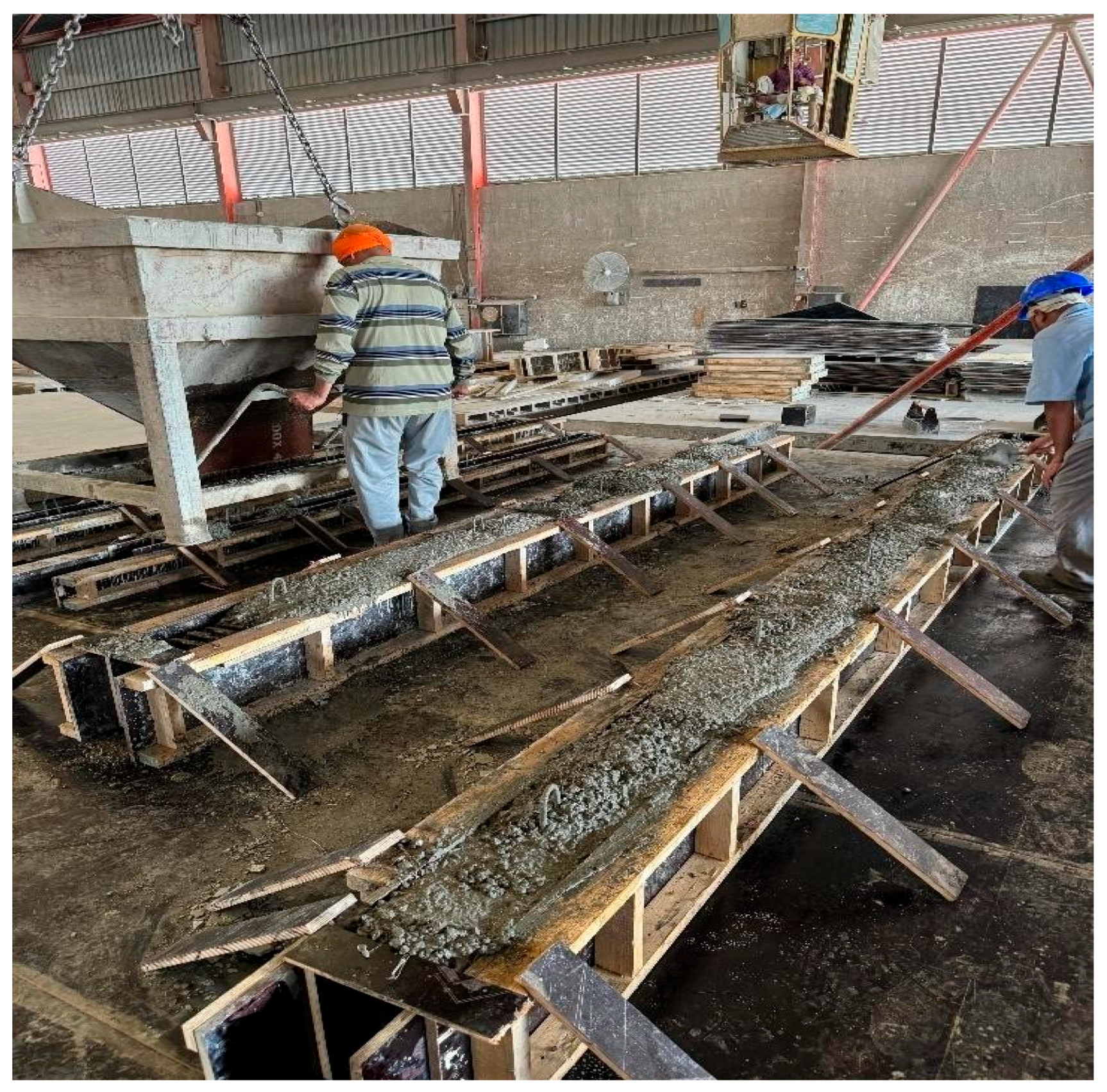
Figure 2-5.
Surface preparation and grooving procedure (c) completed groove pattern.
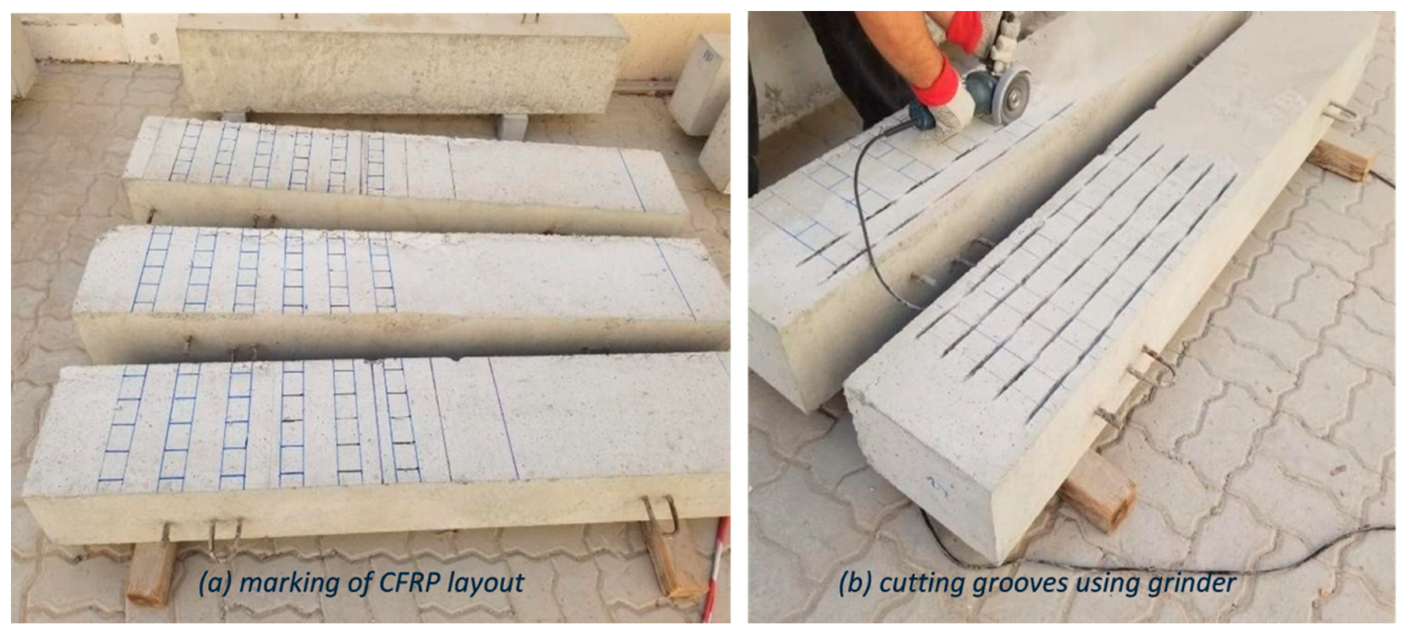
Figure 2-6.
CFRP Bonding procedure.
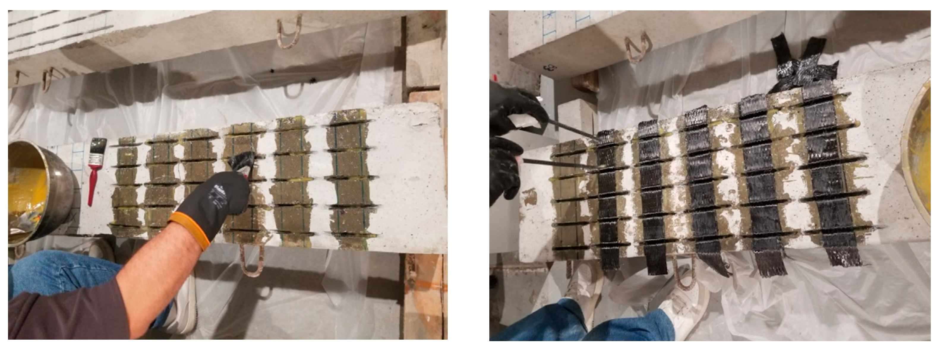
Figure 2-7.
Instron 8806 testing machine.
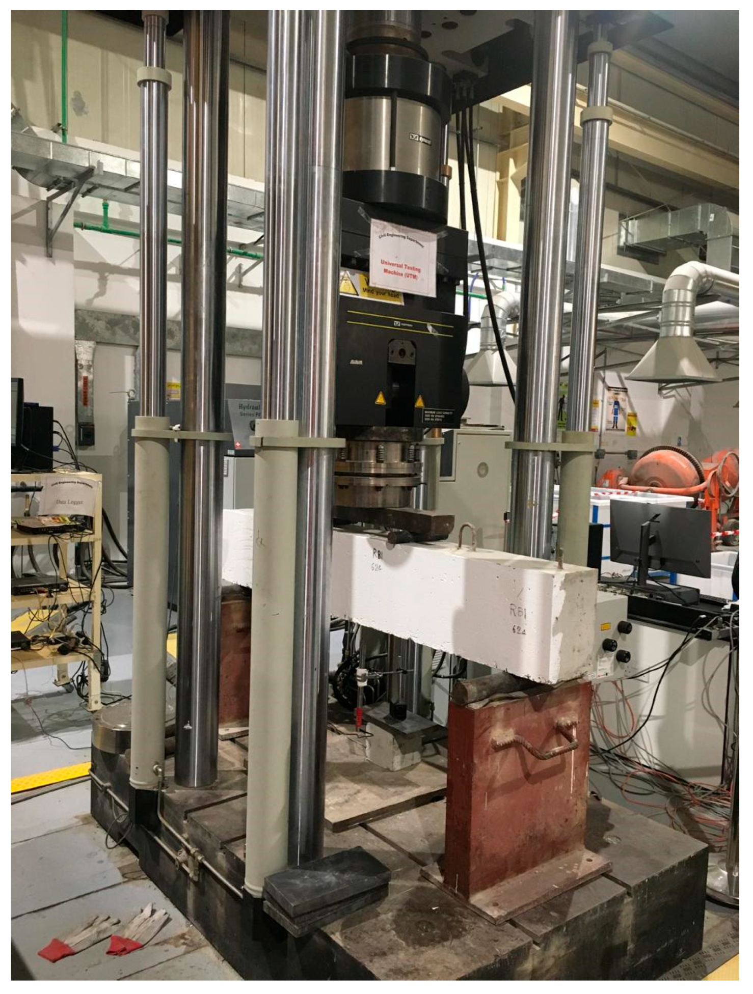
Figure 2-8.
Test Setup.
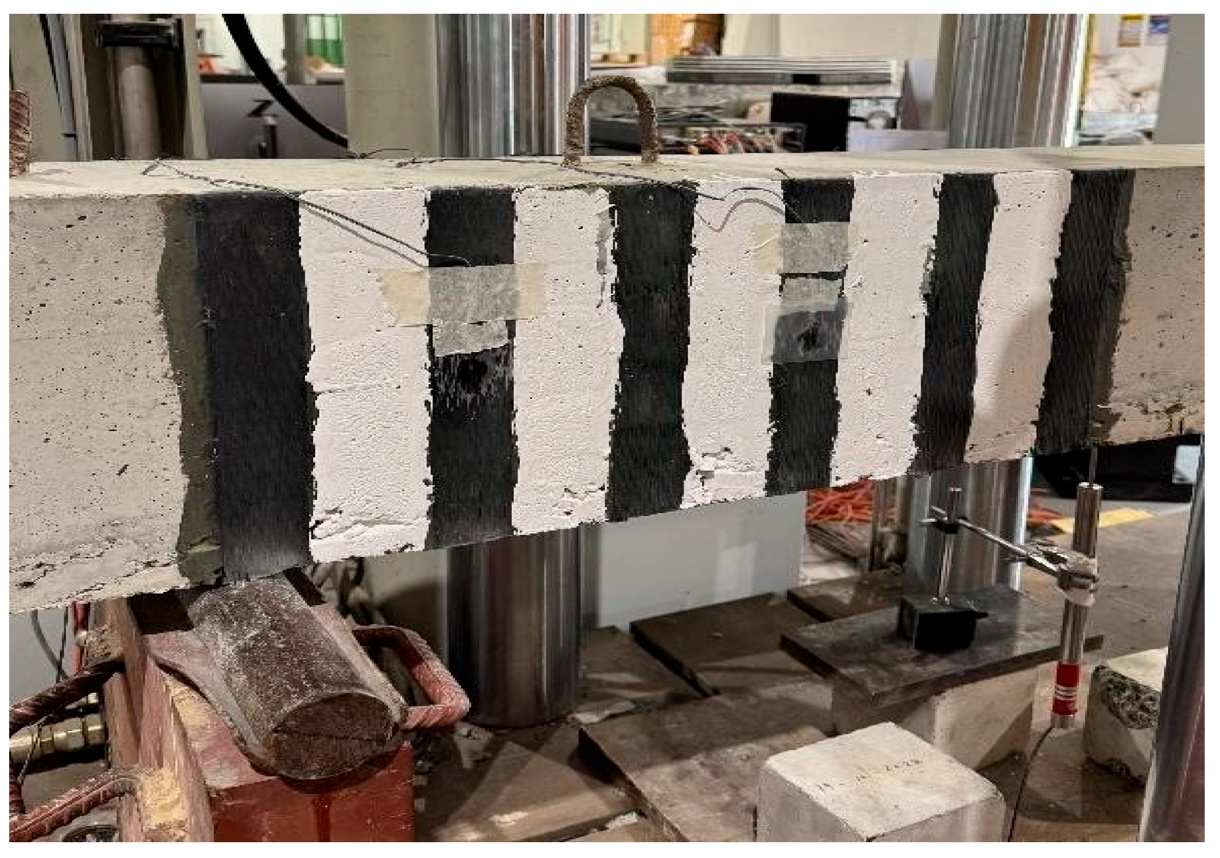
Figure 3-9.
Mode of failure of RB1.
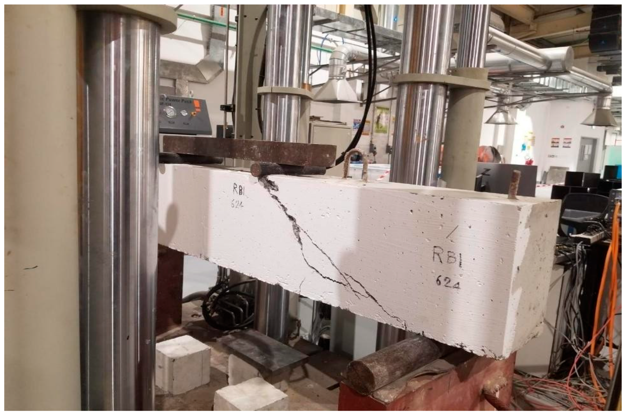
Figure 3-10.
Load-Displacement curves B2 and B3 compared to RB1.
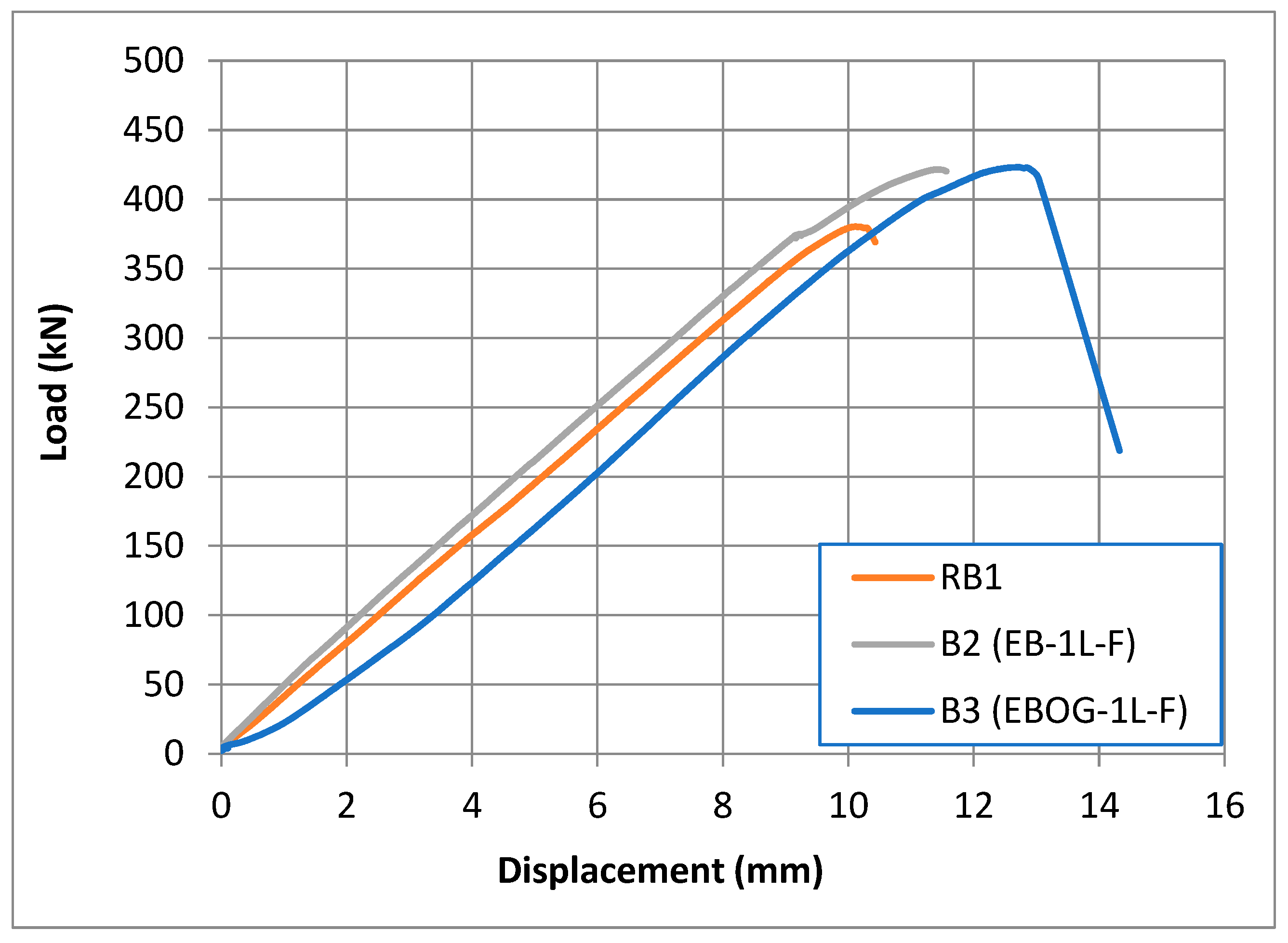
Figure 3-11.
Failure Mode of B2.
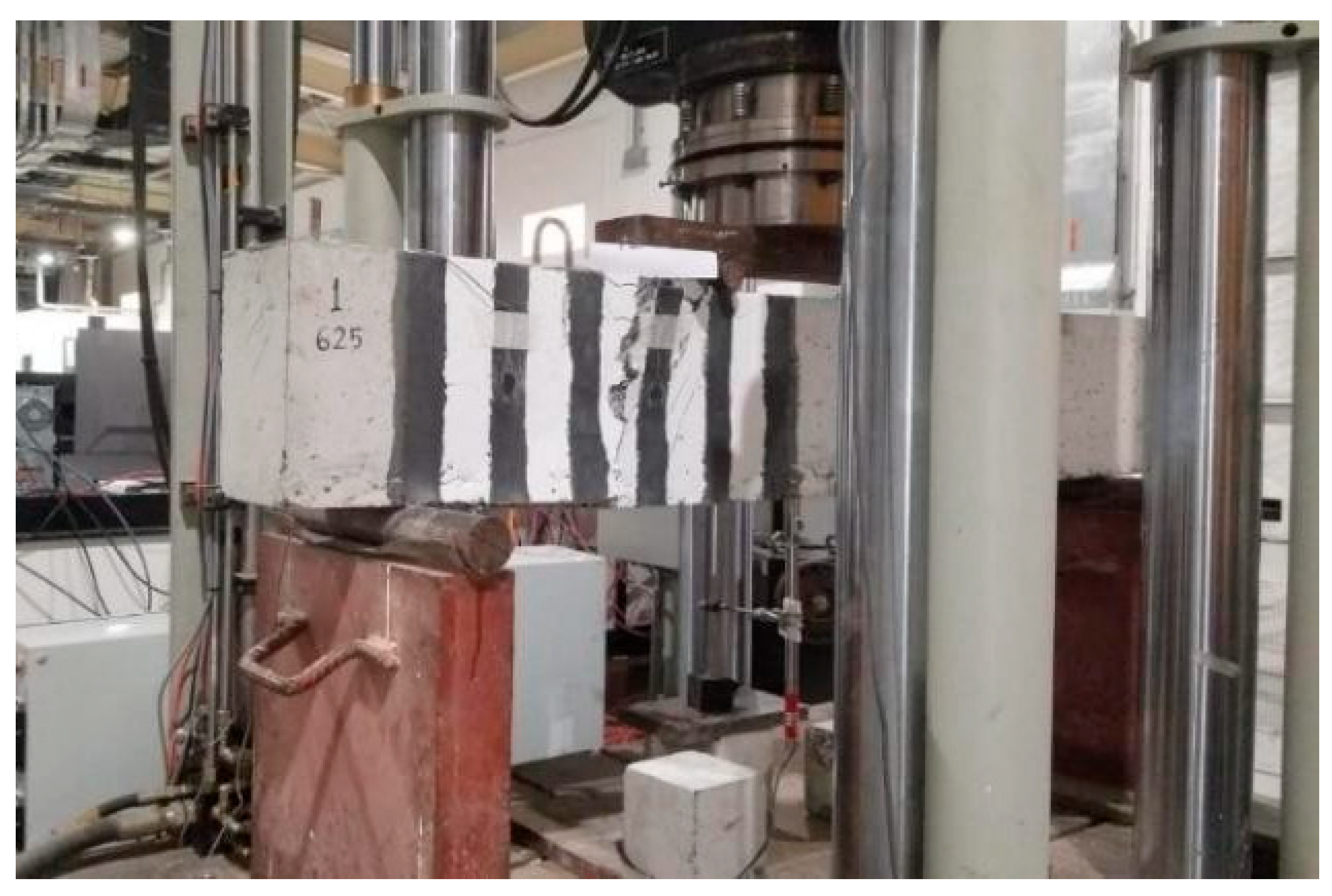
Figure 3-12.
Failure mode of B3 specimen.
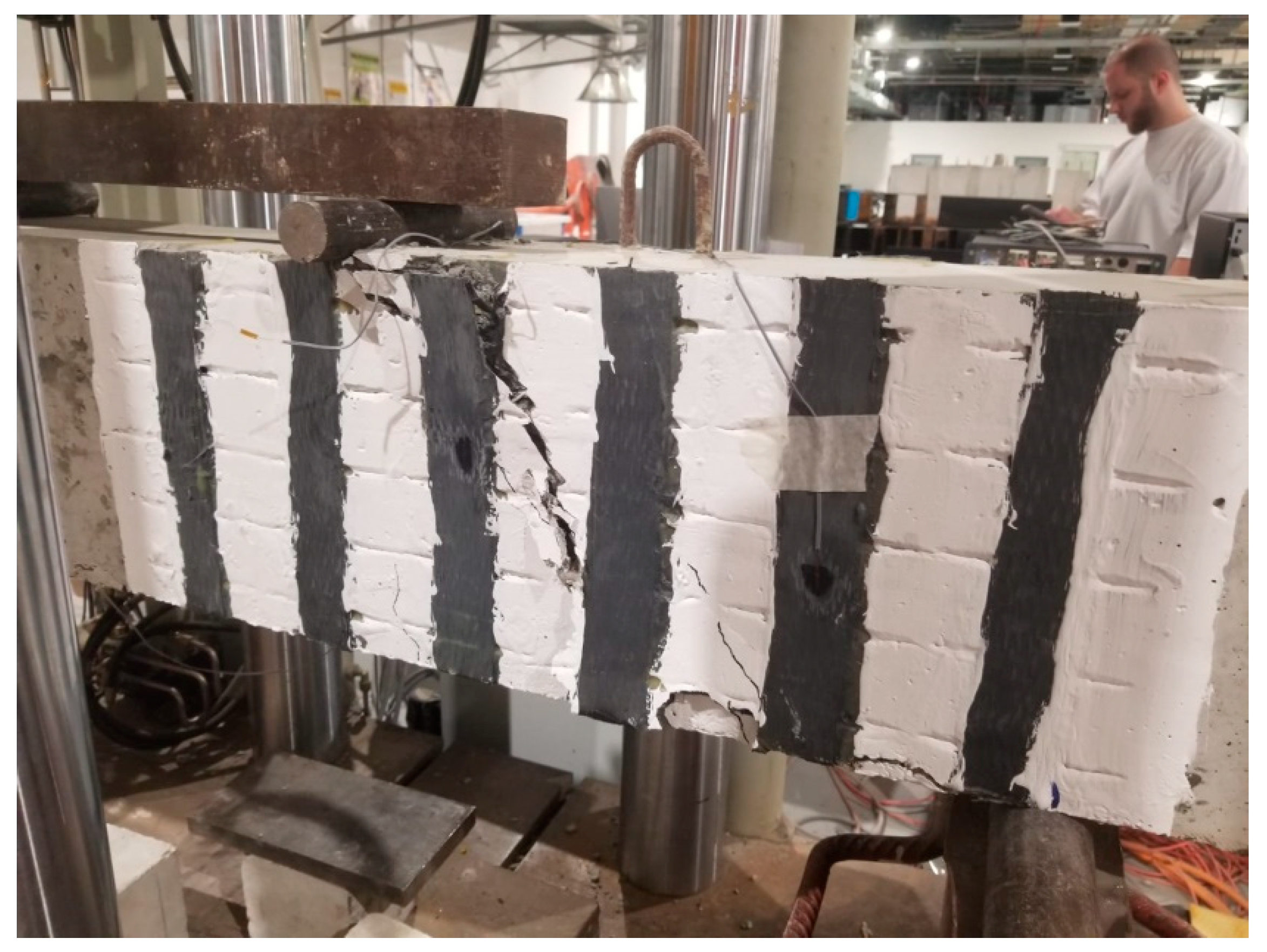
Figure 3-13.
Load-Displacement curve RB1, B4, and B5.
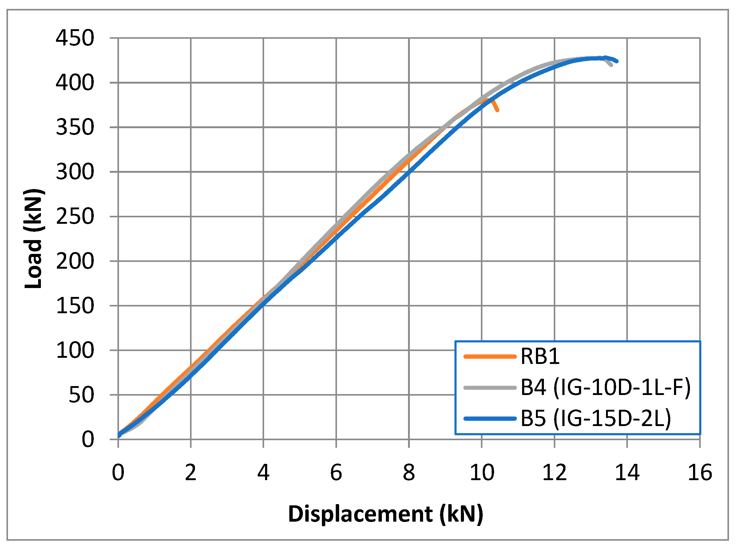
Figure 3-14.
Failure Mode of B4.
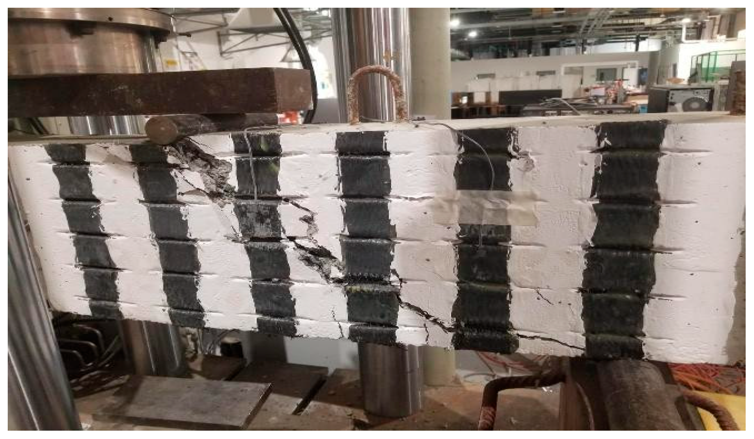
Figure 3-15.
Failure Mode of B5.
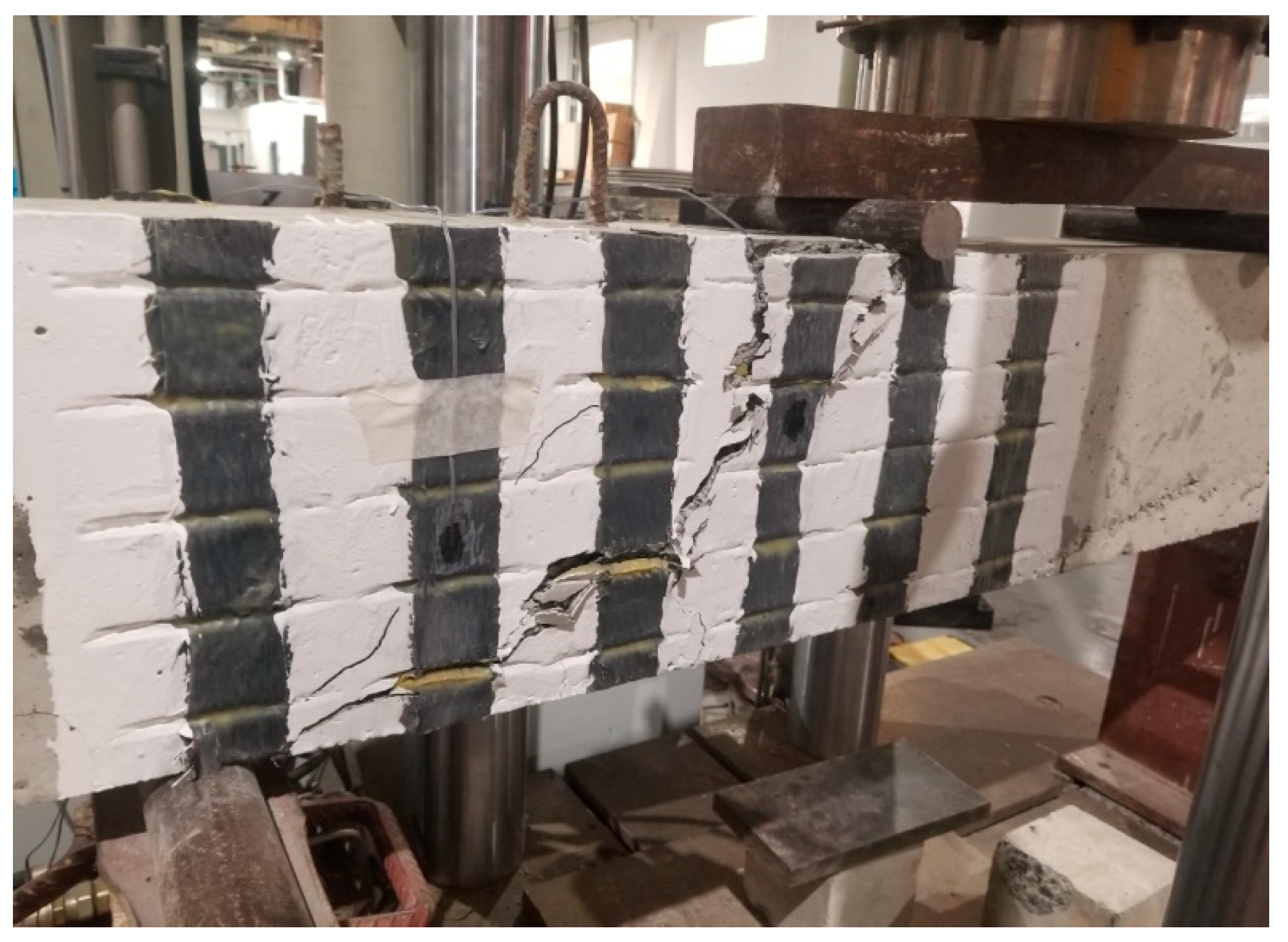
Figure 3-16.
Load-Displacement curve RB1, B2, B6 and B7.
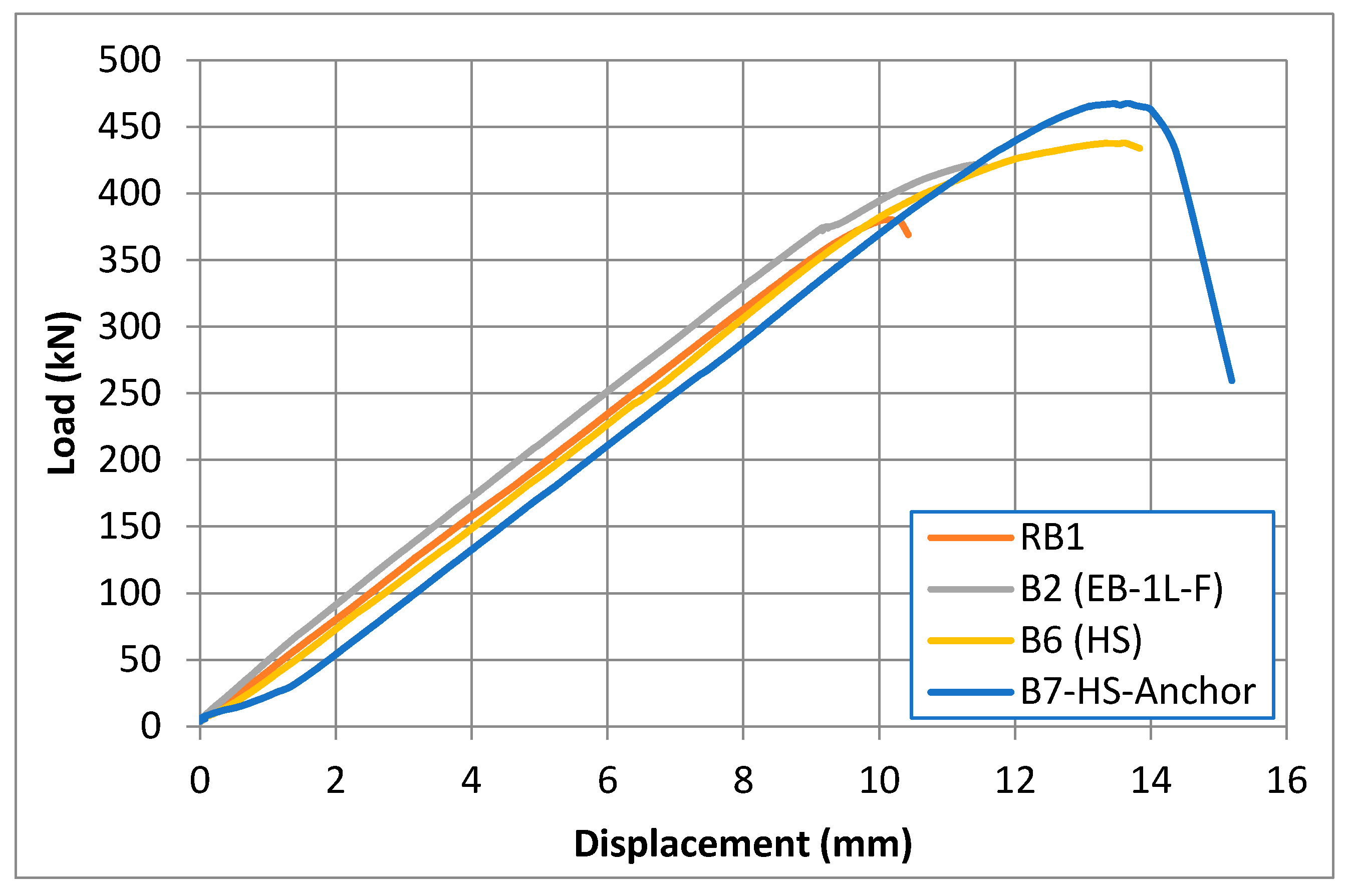
Figure 3-17.
Failure mode of B6.
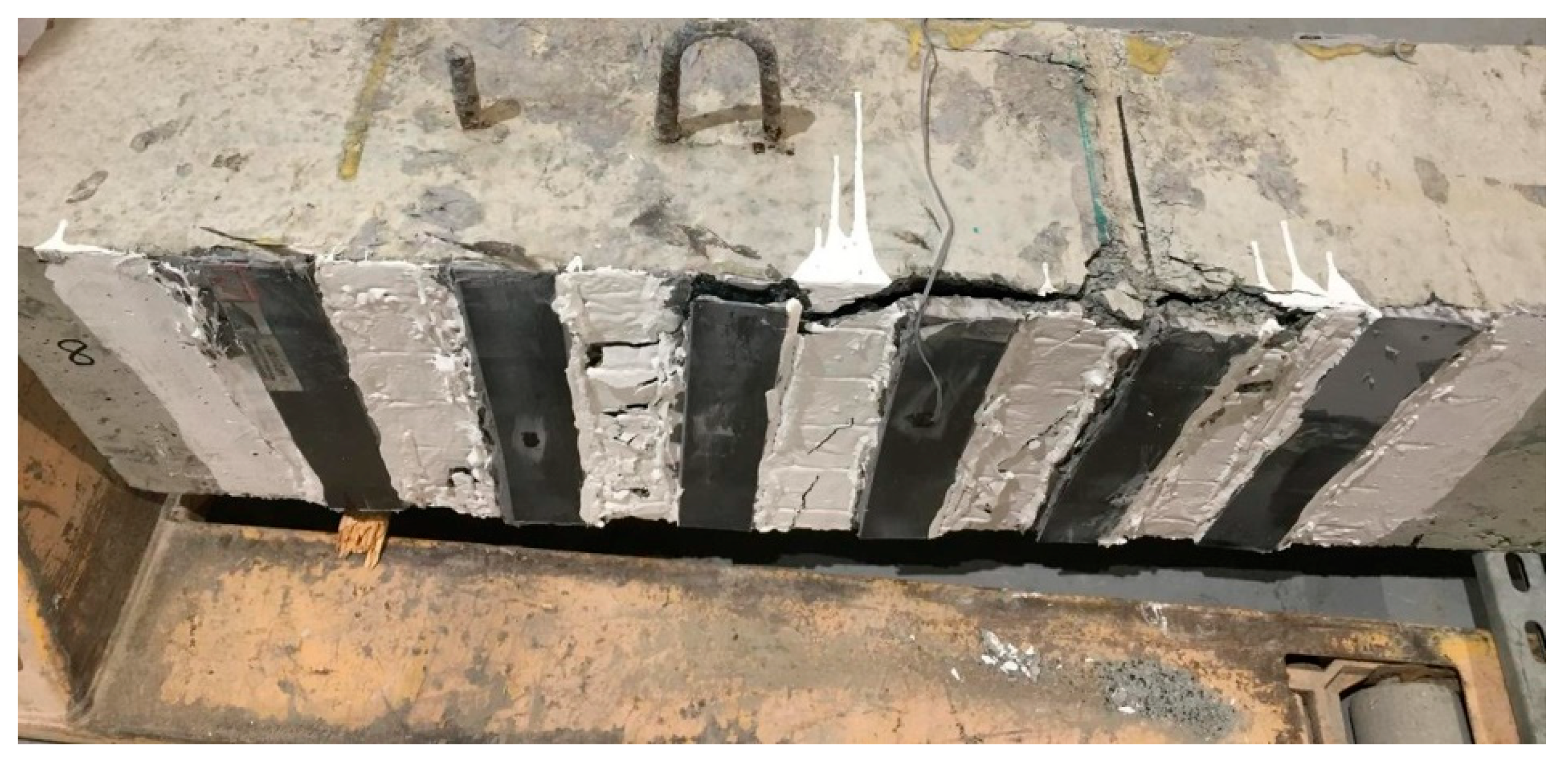
Figure 3-18.
Failure mode of B7.
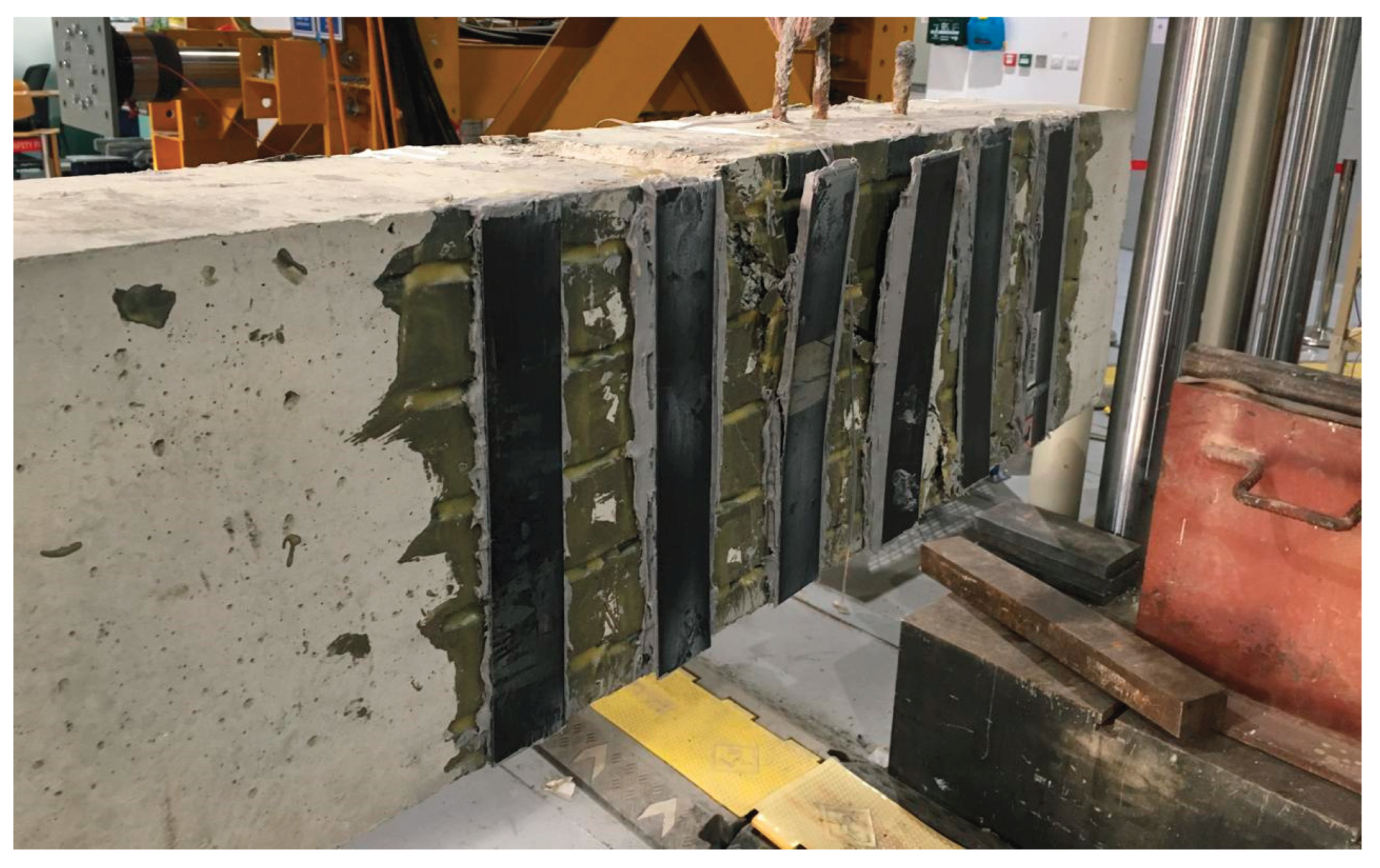
Table 2-2.
Mechanical properties of CFRP fabric (230 g/m2).
| Property | Fabric CFRP | Laminate CFRP |
|---|---|---|
| Tensile strength (MPa) | 3500–4000 | 2800–3000 |
| Elastic modulus (GPa) | 230–240 | 165–210 |
| Thickness (mm) | 0.167 | 1.2–1.4 |
| Density (kg/m3) | 1800 | 1600 |
| Ultimate strain (%) | 1.5–1.7 | 1.3–1.5 |
Disclaimer/Publisher’s Note: The statements, opinions and data contained in all publications are solely those of the individual author(s) and contributor(s) and not of MDPI and/or the editor(s). MDPI and/or the editor(s) disclaim responsibility for any injury to people or property resulting from any ideas, methods, instructions or products referred to in the content. |
© 2026 by the authors. Licensee MDPI, Basel, Switzerland. This article is an open access article distributed under the terms and conditions of the Creative Commons Attribution (CC BY) license (http://creativecommons.org/licenses/by/4.0/).
Copyright: This open access article is published under a Creative Commons CC BY 4.0 license, which permit the free download, distribution, and reuse, provided that the author and preprint are cited in any reuse.


