

Submitted:
28 July 2026
Posted:
29 July 2026
You are already at the latest version
Abstract
This paper presents a compact microstrip patch antenna operating at 5.9 GHz with enhanced bandwidth and reduced cross-polarization levels. The proposed design employs a single edge-notch technique to achieve bandwidth doubling compared to the conventional patch antenna. However, this modification introduces elevated cross-polarization levels across the operating band. To address this issue, two symmetric cuts are introduced in the ground plane, significantly suppressing cross-polarization while maintaining the extended bandwidth. The antenna is designed and simulated using MATLAB Antenna Toolbox, with comprehensive analysis of VSWR, impedance bandwidth, radiation patterns, gain, and directivity characteristics. With an impedance bandwidth exceeding 800 MHz, the final design is well-suited for Vehicle-to-Everything (V2X) communications, Industrial, Scientific, and Medical (ISM) band applications, and unmanned aerial vehicle (UAV) systems—all of which require a compact form factor and stable radiation characteristics. The proposed antenna demonstrates improved performance with H-plane cross-polarization levels reduced by 8.5–23 dB (depending on frequency) compared to the edge-notched configuration without ground modifications, while maintaining a compact footprint.
Keywords:
patch antenna
; edge-notch
; cross-polarization reduction
; V2X communications
; 5.9 GHz
; ground plane modification
; UAV antennas
I. Introduction
The rapid growth of wireless communication systems has created increasing demand for compact, efficient antennas operating in the 5-6 GHz frequency range. The 5.9 GHz band has gained particular importance for Vehicle-to-Everything (V2X) communications [1]-[4], Unmanned Aerial Vehicles [5]-[12], and Industrial-Scientific-Medical (ISM) applications [13,14]. Additionally, the proliferation of unmanned aerial vehicles (UAVs) and drone technology requires lightweight, low-profile antennas with stable radiation characteristics [6,11,12]. Microstrip patch antennas are widely favored for these applications due to their compact size, low cost, ease of fabrication, and compatibility with printed circuit board technology. However, conventional patch antennas suffer from narrow bandwidth limitations, typically 1-5%, which restricts their applicability in modern wideband communication systems.
Various bandwidth enhancement techniques have been proposed in literature, including parasitic elements, stacked patches, aperture coupling, and slot/notch implementations [15]-[20]. Among these techniques, edge-notching is a simple yet effective method for significantly improving bandwidth [21]. However, such modifications often degrade polarization purity, resulting in elevated cross-polarization levels that can compromise system performance in polarization-sensitive applications [22]-[24].
To overcome high cross-polarization (XP) levels caused by higher-order modes and orthogonal fringing fields in microstrip patches, Defected Ground Structures (DGS) were introduced by Guha et al. [25] as an elegant physical suppression technique. By strategically etching defect patterns into the metallic ground plane beneath the radiator, the surface current distribution is perturbed to suppress unwanted cross-polarized fields without altering the dominant mode input impedance or co-polarized radiation [25,26]. Subsequent developments, comprehensively surveyed by Guha et al. [27], have established DGS as a robust alternative to complex dual-feed or thick-substrate techniques for achieving high Cross-Polarization Discrimination (XPD).
This paper presents a systematic approach to bandwidth enhancement through edge-notching while simultaneously addressing the cross-polarization issue through symmetric ground plane modifications. This work extends our earlier study [21], which established the single edge-notch technique for bandwidth enhancement (corresponding to Antennas 1 and 2 in the present paper), by introducing a symmetric ground-plane modification (Antenna 3) that suppresses the resulting cross-polarization while preserving the extended bandwidth. The proposed antenna achieves bandwidth doubling compared to the reference design while keeping the H-plane cross-polarization level negative (below the co-polarized level) across the extended operating band.
It should be emphasized that the individual techniques employed here — edge-notching for bandwidth enhancement and defected ground structures for cross-polarization suppression — are each individually well established in the literature. The contribution of this work is not a new technique, but a concrete, low-complexity engineering design that combines these two established mechanisms to simultaneously satisfy the bandwidth and polarization-purity requirements of the 5.9 GHz V2X band — a combination the author was unable to find previously demonstrated for this specific application and frequency range. The proposed solution requires only planar geometric modifications, without additional layers, parasitic elements, or complex feed networks, making it readily reproducible for practical antenna design.
II. Antenna Design and Configuration
A. Antenna Geometry
We performed a comparative analysis using three antennas simulated with MATLAB's Antenna Toolbox. All three antennas are fabricated on a Rogers/Duroid 5880 substrate with a dielectric constant of εr = 2.2 and a thickness of h = 1.57 mm. For antennas configuration, the ground plane dimensions (GrX, GrY) are determined based on the conventional criteria, where the ground plane length and width correspond to the respective patch dimensions plus 6h. Figure 1 shows geometry of all three antennas.
The antennas are fed by a coaxial probe. Dimensions of the probe were optimized for resonance near 5.9 GHz. The detailed geometrical parameters for each design are summarized in TABLE I.
The first configuration (Antenna 1) serves as a reference antenna and is designed to resonate at 5.9 GHz without any slots. This antenna exhibits a bandwidth of approximately 250 MHz, and its gain and directivity values correspond to standard transmission line model equations [9].

Table 1.
Dimensions of the Patch Antennas (mm).
| Parameter | Antenna 1 | Antenna 2 | Antenna 3 |
|---|---|---|---|
| Patch length (Lx) | 15.95 | 17.9 | 17.6 |
| Patch width (Wy) | 20.1 | 32 | 31.5 |
| Feed offset from center (f) | -3.6 | -6 | -6.4 |
| Ground Plane: GrX; GrY | 25.37, 29.52 | 27.32, 41.42 | 27.02, 40.92 |
| Notch depth (a) | — | 2.4 | 2.75 |
| Notch width (b) | — | 18 | 21.7 |
| Patch-Slot Distance (q) | — | — | -0.5 |
| Gnd_Slot_Width (c) | — | — | 3.5 |
| Gnd_Slot_Length (d) | — | — | 24 |
The second configuration (Antenna 2) incorporates a single edge-notch, which expands the bandwidth by more than twofold compared to the reference antenna. However, Antenna 2 exhibits an increased cross-polarization level, which is unacceptable for applications with strict polarization constraints.
To mitigate this issue, the third design (Antenna 3) suppresses the cross-polarized components by introducing two symmetrical slots into the ground plane. Figure 1 illustrates the geometries of all three antenna versions: the reference design (Antenna 1), the design with an edge notch (Antenna 2), and the final configuration featuring both an edge notch and two ground-plane slots (Antenna 3). The two symmetrical slots etched into the ground plane of Antenna 3 are highlighted in light blue.
B. Bandwidth Enhancement via Edge-Notching
To extend the impedance bandwidth, a single rectangular notch is introduced at the radiating edge of the patch. This modification perturbs the current distribution and introduces an additional resonant mode that merges with the fundamental mode, effectively doubling the operational bandwidth. The notch dimensions are optimized through parametric studies to achieve maximum bandwidth while maintaining acceptable radiation characteristics.
C. Cross-Polarization Reduction Technique
The edge-notched configuration, while providing bandwidth enhancement, generates asymmetric current distributions that result in elevated cross-polarization levels, particularly in the H-plane radiation pattern. To mitigate this effect, two symmetric rectangular cuts are introduced in the ground plane beneath the patch edges. These modifications restore current symmetry and suppress unwanted cross-polarized radiation components without significantly affecting the impedance bandwidth or co-polarized radiation characteristics.
All detailed geometric parameters, as well as simulation results such as VSWR, bandwidth, radiation patterns, and gain/directivity for the three antennas, were calculated using the MATLAB Antenna Toolbox.
III. Simulation Results and Discussion
The antenna designs were simulated using MATLAB Antenna Toolbox, which employs Method of Moments (MoM) based solvers for accurate prediction of antenna performance parameters.
A. Impedance Characteristics
Figure 2 demonstrates the VSWR response and Smith chart of Antenna 1. The impedance bandwidth is defined as the frequency range over which the VSWR remains below 2. According to this criterion, Antenna 1 exhibits an impedance bandwidth of approximately 260 MHz (5.70–5.96 GHz), corresponding to a fractional bandwidth of 4.4% referenced to the design frequency of 5.9 GHz.
Figure 3 shows the VSWR response and Smith chart of Antenna 2. The introduction of the edge-notch slot increases the impedance bandwidth to 601.5 MHz (5.475–6.077 GHz), corresponding to a fractional bandwidth of 10.19% referenced to the design frequency of 5.9 GHz.
Figure 4 presents the VSWR response and Smith chart of Antenna 3. The addition of symmetric ground-plane cuts further extends the impedance bandwidth to 846.4 MHz (5.649–6.495 GHz), corresponding to a fractional bandwidth of 14.35% referenced to the design frequency of 5.9 GHz.
The Smith charts in Figure 2, Figure 3 and Figure 4 further illustrate the progressive improvement in impedance matching achieved by the proposed design modifications, particularly over the extended operating bandwidth.
B. 2D Radiation Patterns — E-Plane and H-Plane Co- and Cross-Polarized Patterns
The simulated co-polarized (co-pol) and cross-polarized (cross-pol) radiation patterns for Antenna 1, Antenna 2, and Antenna 3 in both the E-plane (φ = 0°) and H-plane (φ = 90°) at 5.8 GHz, 5.9 GHz, and 6.0 GHz are depicted in Figure 5, Figure 6 and Figure 7.
The radiation pattern analysis reveals several important observations:
Co-polarized patterns: All three configurations maintain stable broadside radiation with similar beamwidth characteristics in both E-plane and H-plane.
Cross-polarization performance:
As it follows from Figure 5 to 7, in the E-plane the cross-polarization levels for all three configurations are exceptionally low (well below –40 dB), and are therefore not visible within the plotted dynamic range.
A comparative evaluation in the H-plane reveals distinct structural differences in cross-polarization performance:
— Antenna 1 exhibits typical microstrip patch behavior, maintaining a sharp broadside null with maximum cross-pol levels suppressed below −25 dB within the main beam region.
— Antenna 2 demonstrates a significant degradation in polarization purity, where the H-plane cross-pol levels rise dramatically, peaking as high as −1 dB to −5 dB away from broadside.
— Antenna 3 with ground plane cuts successfully restores polarization integrity, demonstrating a well-defined broadside null and keeping the cross-pol levels strongly suppressed below −20 dB across the operational bandwidth.
C. Cross-Polarization Level in the 5.5–6.5 GHz Range
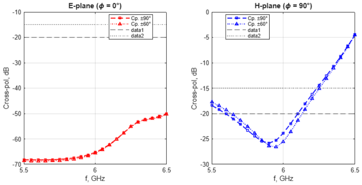
Figure 8, Figure 9 and Figure 10 illustrate the sector-averaged (±60° and ±90°) cross-polarization levels as a function of frequency for the three investigated antenna configurations in the E-plane (φ = 0°) and H-plane (φ = 90°). To evaluate performance rigorously, each design is assessed strictly within its respective −10 dB impedance bandwidth: Antenna 1 (BW = 260 MHz, 5.700–5.960 GHz, 4.44%), Antenna 2 (BW = 601.5 MHz, 5.475–6.077 GHz, 10.19%), and Antenna 3 (BW = 846.4 MHz, 5.649–6.495 GHz, 14.30%).
In-Band Polarization Performance of Individual Antennas
— Antenna 1 (Baseline Conventional Patch): Maintains exceptional polarization purity within its narrow bandwidth (5.700–5.960 GHz). In the E-plane, cross-polarization remains virtually flat below −67 dB. In the H-plane, the sector averages reach a deep resonance minimum between −28 dB and −30 dB around 5.75 GHz, remaining strictly below −25 dB across its active band.
— Antenna 2 (Wideband Solid-Ground Patch): Exhibits strong polarization asymmetry between planes. In the E-plane, cross-polarization stays extremely clean (below −50 dB) across its entire operational range (5.475–6.077 GHz). However, its H-plane performance deteriorates rapidly above 5.7 GHz, monotonically climbing from −16 dB up to −2 dB at its upper impedance boundary (6.077 GHz).
— Antenna 3 (DGS-Optimized Patch): Features a slotted ground plane that stabilizes cross-polarization across an expanded bandwidth (5.649–6.495 GHz). In the E-plane, the level stays below −68 dB up to 6.0 GHz and rises smoothly to −50 dB at the upper band edge. In the H-plane, the defected structure creates a pronounced resonance null near the target 5.9 GHz band, keeping sector averages between −26 dB and −27 dB and maintaining values below −15 dB up to 6.2 GHz.
Comparative Cross-Polarization Analysis: Antenna 2 vs. Antenna 3
A direct comparison highlights the effectiveness of the defected ground structure (DGS) in suppressing unwanted cross-polarized radiation:
— E-Plane enhancement (5.5–6.2 GHz): Both antennas exhibit robust suppression in the E-plane; however, Antenna 3 achieves an additional 10–15 dB suppression over Antenna 2 across the shared 5.5–6.0 GHz range, holding a baseline floor near −68 dB compared to −58 dB to −73 dB for Antenna 2.
— Substantial H-plane improvement (5.5–6.2 GHz): The primary advantage of Antenna 3 manifests in the H-plane within the shared operating band. At the target 5.9 GHz V2X frequency, Antenna 2 exhibits severe degradation with sector averages reaching −3 dB to −4 dB. In contrast, the ground slots in Antenna 3 introduce a deep resonant null, dropping the sector-averaged cross-polarization to −26 dB to −27 dB—representing a massive 23 dB improvement over Antenna 2.
— High-frequency behavior (6.2–6.5 GHz): Toward the upper limit of the sweep (> 6.2 GHz), the slot dimensions lose their optimal sub-wavelength filtering properties, causing cross-polarization levels in both antennas to degrade. Nevertheless, Antenna 3 remains superior: while Antenna 2 experiences a complete modal inversion with H-plane sector levels rising to +9 dB at 6.3 GHz, Antenna 3 restrains these levels to −4 dB at 6.5 GHz.
In summary, the integration of DGS slots in Antenna 3 expands the operational fractional bandwidth to 14.30% while drastically enhancing spatial polarization purity across the entire shared operating spectrum.
Table 2.
Comparative Cross-Polarization Metrics in the H-Plane (ϕ = 90°).
| Metric. | Antenna 2 (5.475–6.077 GHz) | Antenna 3 (5.649–6.495 GHz) |
|---|---|---|
| Best (minimum) sector-averaged cross-pol level | ≈ −18.5 dB (at 5.5 GHz) | ≈ −26 to −27 dB (at 5.9 GHz) |
| −20 dB crossing frequency | ≈ 5.95 GHz | ≈ 6.05 GHz |
| 0 dB crossing frequency | ≈ 6.05–6.10 GHz (in band) | Not reached (ends at ≈ −4 dB) |
| Cross-pol level at upper band limit | ≈ 0 dB (inversion threshold) | ≈ −4 dB |
Antenna 3 demonstrates clear superiority over Antenna 2 in suppressing H-plane cross-polarized radiation. The minimum sector-averaged cross-polarization level is improved by approximately 8.5 dB overall, and by a massive 23 dB at the target 5.9 GHz band. Crucially, across its entire extended impedance bandwidth (5.65–6.5 GHz), the cross-polarization level for Antenna 3 remains strictly negative, preserving polarization purity throughout the operational range. In contrast, Antenna 2 experiences severe degradation, reaching the 0 dB threshold before reaching its upper bandwidth edge—representing a critical performance limitation of the conventional solid ground plane.
D. Gain and Radiation Efficiency Analysis
To ensure a rigorous and consistent comparative framework, the radiation characteristics of all three configurations were evaluated under baseline ground plane sizing constraints defined by GndX = Lx + 6h and GndY = Wy + 6h, where h is the substrate thickness.
Table 3.
Radiation Performance Comparison for Baseline Ground Dimensions, (Lx + 6h) × (WY + 6h).
| Parameter / Metric | Antenna 1 (Baseline) | Antenna 2 (Solid Ground) | Antenna 3 (DGS-Optimized) |
|---|---|---|---|
| Impedance bandwidth (−10 dB) | 260 MHz (4.4%) | 601.5 MHz (10.2%) | 846.4 MHz (14.25%) |
| Directivity (D) | 7.16 dBi | 6.53 dBi | 8.48 dBi |
| IEEE gain (G) | 7.04 dBi | 6.46 dBi | 8.43 dBi |
| Realized gain (Grealized) | 6.95 dBi | 6.41 dBi | 8.18 dBi |
| Radiation efficiency (η) | 94.7% | 98.4% | 97.1% |
| H-plane cross-pol at 5.9 GHz | < −25 dB | −3 to −4 dB | −26 to −27 dB |
GIEEE = η · D
Grealized = (1 − |S11|2) · GIEEE
Where the parameters (expressed in linear values, rather than dBi) are defined as follows:
— Grealized — Realized Gain
— GIEEE — IEEE Gain
— D — Directivity
— η — Radiation Efficiency
— S11 — Input Reflection Coefficient
As shown in Table III, conventional solid-ground designs (Antenna 2) suffer from reduced broadside directivity due to unconstrained surface wave propagation across the finite boundary, yielding an IEEE gain of 6.46 dBi. Remarkably, the defected ground structure in Antenna 3 provides a substantial broadside radiation enhancement without increasing the physical footprint, achieving an IEEE gain of 8.43 dBi (a gain improvement of nearly 2 dB over Antenna 2). This enhancement is attributed to slot-induced suppression of higher-order modes and efficient spatial redirection of energy toward the broadside direction. Furthermore, the minimal difference between IEEE Gain (8.43 dBi) and Realized Gain (8.18 dBi) for Antenna 3 confirms excellent input impedance matching alongside high radiation efficiency (97.1%).
Limitations
This study is based exclusively on full-wave numerical simulation (MATLAB Antenna Toolbox, MoM solver). Mesh-convergence analysis and agreement with transmission-line theory for the reference Antenna 1 and Antenna 2 support the reliability of the simulated results. Experimental validation through fabrication and measurement has not been performed and remains an important next step, ideally through collaboration with a laboratory equipped for antenna prototyping and anechoic-chamber characterization.
IV. Conclusions
This paper has presented a practical engineering solution for a compact microstrip patch antenna operating at 5.9 GHz that simultaneously achieves enhanced bandwidth and suppressed cross-polarization. Although the constituent techniques are individually known, their specific combination and parametric realization for the 5.9 GHz V2X/ISM band, validated here through detailed simulation, was not identified in prior published work. The key findings are:
— Bandwidth Enhancement: The single edge-notch technique extends the impedance bandwidth from 260 MHz (4.4%) to 601.5 MHz (10.2%), and the addition of the ground-plane cuts extends it further to 846.4 MHz (14.3%, 5.649–6.495 GHz), providing coverage well beyond the 5.9 GHz V2X and ISM band requirements.
— Cross-Polarization Reduction: The introduction of two symmetric cuts in the ground plane reduces the H-plane sector-averaged cross-polarization level by approximately 23 dB at the target 5.9 GHz band and by at least 8.5 dB at its best-case minimum, compared to the edge-notched configuration alone, keeping the cross-polarization level negative (below the co-polarized level) across the full extended impedance bandwidth.
— Performance Stability: The proposed modifications maintain stable gain (6–8 dBi), directivity, and radiation patterns while significantly improving polarization purity.
— Compact Design: The antenna maintains a low-profile, planar structure suitable for integration into space-constrained platforms such as vehicles, UAVs, and wearable devices.
— Design Simplicity: The proposed techniques require only simple geometric modifications without additional layers, parasitic elements, or complex feeding networks, ensuring ease of fabrication and cost-effectiveness.
The antenna demonstrates excellent potential for V2X communications, UAV applications, ISM band systems, and biomedical telemetry where compact size, wide bandwidth, and stable radiation characteristics are essential. Future work will include fabrication and experimental validation of the simulated designs, as well as investigation of array configurations for enhanced gain applications.
References
- Katare, K.K.; Yousaf, I.M.; Lau, B.K. Challenges and solutions for antennas in vehicle-to-everything services. IEEE Commun. Mag. 2022, vol. 60(no. 1), 52–58. [Google Scholar] [CrossRef]
- ETSI EN 302 663, V2.1.1; Intelligent Transport Systems (ITS); Access layer specification for ITS operating in the 5 GHz band. ETSI, 2019.
- IEEE Standard for Information Technology—Wireless LAN Medium Access Control (MAC) and Physical Layer (PHY) Specifications. IEEE Std 802.11-2020; IEEE Standard for Information Technology—Wireless LAN Medium Access Control (MAC) and Physical Layer (PHY) Specifications. IEEE, Dec 2020.
- Rabinovich, V.; Alexandrov, N.; Alkhateeb, B. Automotive Antenna Design and Applications; CRC Press: Boca Raton, FL, USA, 2010. [Google Scholar]
- Kumar S, A.; Susidharan, V.K.; Thiriksha, B.; Mahisha, S.; Aakash, S.J.; Karthika, K.; Sasikala, S. Antennas in Unmanned Aerial Vehicles – A Short Review. 2025 3rd International Conference on Advancements in Electrical, Electronics, Communication, Computing and Automation (ICAECA), Coimbatore, India, 2025; pp. 1–[end page. [Google Scholar] [CrossRef]
- Reis, S.; Silva, F.; Albuquerque, D.; Pinho, P. General Overview of Antennas for Unmanned Aerial Vehicles: A Review. Electronics 2025, 14, 3205. [Google Scholar] [CrossRef]
- Imran, A.Z.M.; Hakim, M.L.; Ahmed, M.R.; Islam, M.T.; Hossain, E. Design of microstrip patch antenna to deploy unmanned aerial vehicle as UE in 5G wireless network. Int. J. Electr. Comput. Eng. (IJECE) 2021, 11, 4202–4213. [Google Scholar] [CrossRef]
- Mahfuz, M.M.H.; Park, C.-W. Review of Patch Antennas used in Drone Applications. IEEE Access 2023, 11, 58367–58384. [Google Scholar] [CrossRef]
- Chen, S.; Liu, X.; Yu, S.; Zhang, A.; Gan, L.; Jing, X. Compact Broadband Four-Port MIMO Antenna for AAV to Assist Automotive Communication. IEEE Internet Things J. 2026, 13, 5442–5451. [Google Scholar] [CrossRef]
- Tewari, N.; Singh, I.; Maurya, S.; Gandotra, P.; Joshi, N.; Srivastava, S. Antenna Designing Using Microstrip Technology for Anti Drone System. 2024 IEEE International Conference on Intelligent Signal Processing and Effective Communication Technologies (INSPECT), Noida, India; 2024, pp. 1–[end page. [CrossRef]
- Donelli, M.; Menon, S.; Mulloni, V.; Marchi, G.; Chiele, I.D. A Light and Compact Circular Polarized Antenna for First-Person-View (FPV) Drones. Electronics 2026, 15, 1150. [Google Scholar] [CrossRef]
- Qin, Y.; Han, M.; Zhang, L.; Mao, C.-X.; Zhu, H. A Compact Dual-Band Omnidirectional Circularly Polarized Filtering Antenna for UAV Communications. IEEE Trans. Veh. Technol. 2023, 72, 16742–16746. [Google Scholar] [CrossRef]
- Saha, D.; Saha, C. MTM-EBG Loaded Circular Patch Antenna for ISM Band Applications. 2022 IEEE Microwaves, Antennas, and Propagation Conference (MAPCON), Trivandrum, India, 2022; pp. 1788–1792. [Google Scholar] [CrossRef]
- Taqdeer, M.M.; Amjad, Q.M.; Zahid, M.; Amin, Y. 2×2 Hexagonal-Shaped Antenna Array for 5.8 GHz ISM Band Applications. 2023 7th International Multi-Topic ICT Conference (IMTIC), Jamshoro, Pakistan, 2023; pp. 1–4. [Google Scholar] [CrossRef]
- Govindarajulu, S.R.; Tarek, M.N.A.; Guerra, M.R.; Hassan, A.; Alwan, E. Modified U-slot patch antenna with large frequency ratio for vehicle-to-vehicle communication. Sensors 2023, 23, 6108. [Google Scholar] [CrossRef] [PubMed]
- John, M.; Ayyappan, M.; Manoj, B.; Rodrigues, S. Bandwidth enhancement of microstrip patch antenna for 5.8 GHz by optimized feed offset. Proc. Int. Conf. Commun. Signal Process. (ICCSP), Melmaruvathur, India, Apr. 2016; pp. 2186–2189. [Google Scholar]
- Saiman, A.M.; Hridoy, M.H.; Haider, M.H.-E.; Sadman, A.A.M.S. Design of a dual-band microstrip patch antenna for 5.9 GHz and 7.25 GHz with enhanced bandwidth. Proc. 3rd Int. Conf. Advancement Electr. Electron. Eng. (ICAEEE), Gazipur, Bangladesh, Apr. 2024; pp. 1–5. [Google Scholar]
- Noor, S.K.; Jusoh, M.; Sabapathy, T.; Rambe, A.H.; Vettikalladi, H.; Albishi, A.M.; Himdi, M. A patch antenna with enhanced gain and bandwidth for sub-6 GHz and sub-7 GHz 5G wireless applications. Electronics 2023, 12, 2555. [Google Scholar] [CrossRef]
- Thakare, V.V.; Singhal, P.K. Bandwidth analysis by introducing slots in microstrip antenna design using ANN. Prog. Electromagn. Res. M. 2009, 9, 107–122. [Google Scholar] [CrossRef]
- Wong, H.; So, K.K.; Gao, X. Bandwidth Enhancement of a Monopolar Patch Antenna With V-Shaped Slot for Car-to-Car and WLAN Communications. IEEE Trans. Veh. Technol. 2016, 65, 1130–1136. [Google Scholar] [CrossRef]
- Rabinovich, V. Bandwidth Enhancement of a 5.9 GHz V2X Patch Antenna Using a Single Edge-Notch Slot. Preprints.org 2026. [Google Scholar]
- Bhardwaj, S.; Rahmat-Samii, Y. A comparative study of C-shaped, E-shaped, and U-slotted patch antennas. Microw. Opt. Technol. Lett. 2012, 54, 1746–1757. [Google Scholar] [CrossRef]
- Zhu, Z.; Chen, C.; Chen, Y.; Wu, W. A broadband low cross-polarization U-slot patch antenna array based on differential feed. Prog. Electromagn. Res. C 2016, 68, 211–219. [Google Scholar] [CrossRef]
- Weigand, S.; Huff, G.H.; Pan, K.H.; Bernhard, J.T. Analysis and Design of Broad-Band Single-Layer Rectangular U-Slot Microstrip Patch Antennas. IEEE Trans. Antennas Propag. 2003, 51, 457–468. [Google Scholar] [CrossRef]
- Guha, D.; Biswas, M.; Antar, Y.M.M. Microstrip Patch Antenna with Defected Ground Structure for Cross Polarization Suppression. IEEE Antennas Wirel. Propag. Lett. 2005, 4, 455–458. [Google Scholar] [CrossRef]
- Kumar, C.; Guha, D. Reduction in Cross-Polarized Radiation of Microstrip Patches Using Geometry-Independent Resonant-Type Defected Ground Structure (DGS). IEEE Trans. Antennas Propag. 2015, 63, 2767–2772. [Google Scholar] [CrossRef]
- Guha, D.; Biswas, S.; Kumar, C. Printed antenna designs using defected ground structures: A review of fundamentals and state-of-the-art developments. In Forum for Electromagnetic Research Methods and Application Technologies (FERMAT); Mar 2014; vol. 2, pp. 1–13. [Google Scholar]
- Shaw, M.; Sarkar, P. Determination of principal resonant frequency and optimum probe position of microstrip antenna using MATLAB. Proc. 9th Int. Conf. Electron., Mater. Eng. Nano-Technol. (IEMENTech), 2026; pp. 1–6. [Google Scholar]
- Narmatha, D.; Abinaya, K. Simulation-based antenna design using MATLAB App Designer. Res. Rev. Electron. Commun. Eng. 2025, 2, 11–21. [Google Scholar]
- Shaik, A.L.H.P.; Zohra, A.; Tanuja, K.; Unnisa, R. Regression-based S11 prediction of slot-loaded microstrip patch antennas using MATLAB Antenna Toolbox. Proc. IEEE Microw., Antennas, Propag. Conf. (MAPCON), 2025; pp. 1–5. [Google Scholar] [CrossRef]
- Prakasam, V.; Reddy, M.N. MATLAB and CST MWS based rectangular microstrip patch antenna design for WLAN applications. Proc. 5th Int. Conf. Recent Trends Electron., Inf., Commun. Technol. (RTEICT), Bangalore, India, 2020; pp. 304–308. [Google Scholar]
Figure 1.
Geometries of three antennas: top view and side view for each antenna.
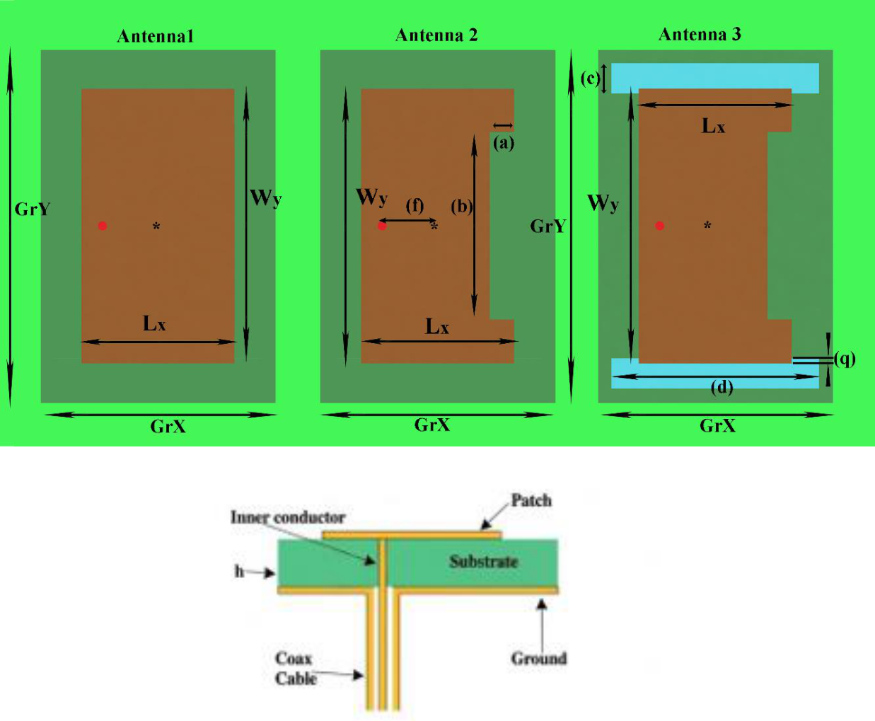
Figure 2.
VSWR and Smith chart for reference Antenna 1.
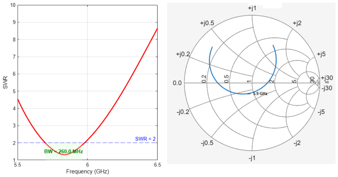
Figure 3.
VSWR and Smith chart for edge-notched Antenna 2.
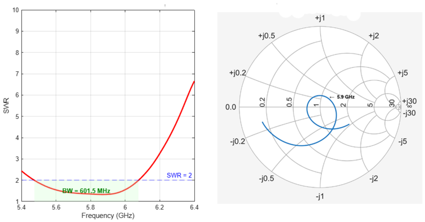
Figure 4.
VSWR and Smith chart for edge-notched Antenna 3 with ground cuts.
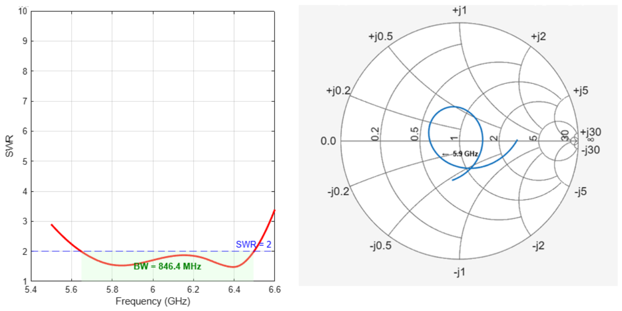
Figure 5.
Co-polarized and cross-polarized radiation patterns in the E- and H-planes for Antenna 1.
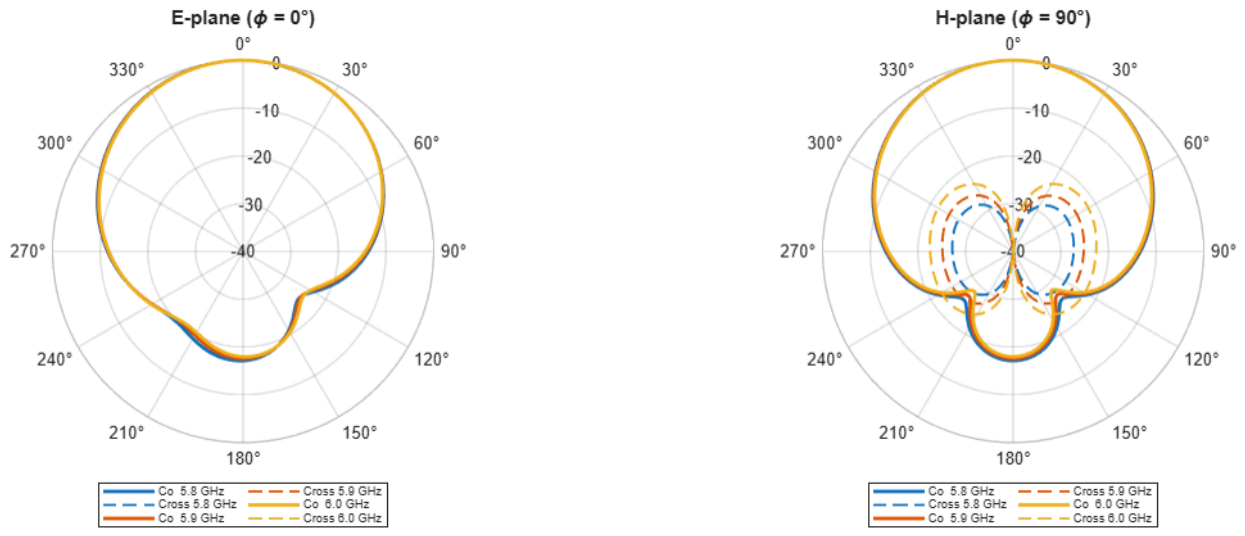
Figure 6.
Co-polarized and cross-polarized radiation patterns in the E- and H-planes for Antenna 2.
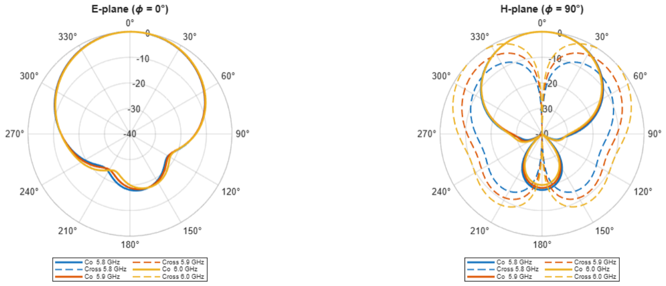
Figure 7.
Co-polarized and cross-polarized radiation patterns in the E- and H-planes for Antenna 3.
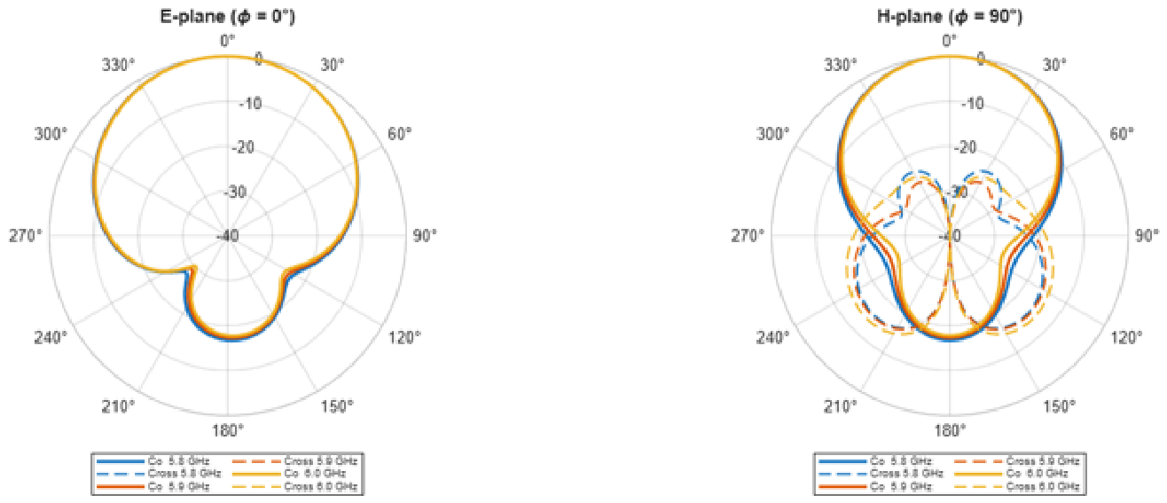
Figure 8.
Cross-polarization sector-averaged sweep for Antenna 1.
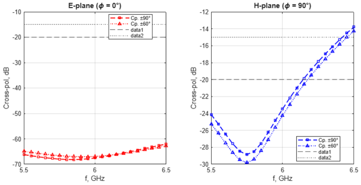
Figure 9.
Cross-polarization sector-averaged sweep for Antenna 2.
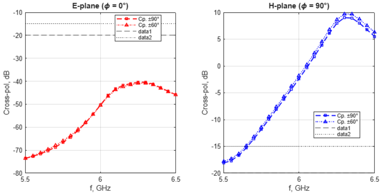
Figure 10.
Cross-polarization sector-averaged sweep for Antenna 3.
Disclaimer/Publisher’s Note: The statements, opinions and data contained in all publications are solely those of the individual author(s) and contributor(s) and not of MDPI and/or the editor(s). MDPI and/or the editor(s) disclaim responsibility for any injury to people or property resulting from any ideas, methods, instructions or products referred to in the content. |
© 2026 by the authors. Licensee MDPI, Basel, Switzerland. This article is an open access article distributed under the terms and conditions of the Creative Commons Attribution (CC BY) license (http://creativecommons.org/licenses/by/4.0/).
Copyright: This open access article is published under a Creative Commons CC BY 4.0 license, which permit the free download, distribution, and reuse, provided that the author and preprint are cited in any reuse.