

Submitted:
16 July 2026
Posted:
20 July 2026
You are already at the latest version
Abstract
Aim. To evaluate the three-dimensional adaptation of prefabricated Bio-Root inlays fabricated from impressions of simulated immature permanent root canals using four techniques: direct intraoral scanning (A), a light-body rubber impression digitized with an intraoral scanner (B), cone-beam computed tomography (CBCT)-based design (C), and a conventional indirect technique (D). Methodology. Ten standardized simulated immature roots (extracted mandibular premolars prepared to a 1.5 mm apical diameter and 10 mm length) were used in a within-specimen comparative design, with each root receiving inlays fabricated by all four techniques. After fabrication and seating of the bioceramic inlays, the void percentage around each inlay was quantified by CBCT at the coronal, middle, and apical thirds relative to the baseline empty-canal volume. Data were analyzed using the Friedman, Wilcoxon signed-rank (Bonferroni-corrected), and linear mixed-model tests (α = 0.05). Results: Technique significantly affected void percentage (F(3,104) = 12.87, p < 0.001). Technique B had the lowest mean void percentage (7.95 ± 4.41%), followed by A (9.52 ± 5.77%), C (13.82 ± 6.93%), and D (14.97 ± 8.45%). Void percentage increased apically (coronal 6.73%, middle 11.10%, apical 16.72%). Differences were non-significant coronally (p = 0.732) but significant in the middle (p = 0.016) and apical (p < 0.001) thirds, with Technique B providing the best apical adaptation. Conclusions. The impression method significantly affected inlay adaptation. A light-body rubber impression digitized with an intraoral scanner yielded the best overall and apical fit, supporting digital workflows, particularly those using digitized physical impressions, for apexification. Adaptation deteriorated toward the apex regardless of technique.
Keywords:
digital workflow
; immature teeth
; intraoral scanner
; cone-beam computed tomography
; bio-root inlay
1. Introduction
Immature necrotic permanent teeth pose a unique challenge for dental practitioners because of their complex treatment requirements. Various materials have been introduced to enhance apical closure, including calcium silicate-based cements. Modern materials in this family, such as bioceramics, offer improved handling properties and are commercially available in pre-mixed forms, facilitating their use in endodontic procedures and reducing discoloration compared with earlier generations [1,2,3].
The delivery and condensation systems used for calcium silicate-based cements significantly affect the sealing ability of the root canal system, a critical determinant of endodontic success [1,4]. Bio-Root inlays represent a novel approach to apexification that does not require conventional delivery and condensation systems: an impression of the immature root canal space is taken and used to fabricate a custom mold filled with calcium silicate cement. After setting, the material forms a ready-to-use inlay that conforms precisely to the root canal space, streamlining the conventional steps of material delivery and condensation with calibrated pluggers [5,6].
This concept has been further developed to incorporate a fiber post into the Bio-Root inlay. The post facilitates handling and placement within the canal, ensuring a precise fit before the interface is sealed with an appropriate sealer. It also supports subsequent coronal restoration, particularly for extensively damaged immature teeth [7].
To date, despite the technical advancement of the Bio-Root inlay concept, no preferred method has been established for obtaining impressions of immature permanent root canals, despite the various techniques described in the literature.
It has been reported that impressions of immature permanent root canals can be obtained using light silicone [5,6,7]. Digital scanners have also been proposed for recording impressions when designing cores and post-and-cores for prepared canals [8,9]. Furthermore, the canal space shape can be captured using three-dimensional (3D) radiographic images obtained through cone-beam computed tomography (CBCT). This has been used in endodontic treatments to accurately determine the working length [10], evaluate canal shapes before and after preparation, assess the efficiency of preparation files [11], guide drilling of calcified canals [12], create 3D-printed macro-models of teeth for educational purposes [13], and detect obturation gaps and voids [14].
This article introduces a novel research concept not previously reported in the literature, aiming to advance apexification treatment by integrating digital workflows. The proposed methodology focuses on optimizing the acquisition of immature root canal morphology for fabricating Bio-Root inlays. Three digital approaches are proposed: designing the inlay from a direct intraoral scan of the immature root canal, from cone-beam computed tomography (CBCT) data, or from a digitally scanned light-body silicone impression. These digital techniques will be evaluated alongside a conventional impression-based method, which serves as the control.
While a perfect void-free interface is theoretically ideal, in clinical practice the residual void space is typically filled with the bioceramic sealer. However, minimizing sealer thickness and interfacial voids remains important because thicker sealer films are generally more susceptible to dissolution and microleakage, potentially compromising the long-term seal [1,3,14].
The null hypothesis was that all Bio-Root inlay design methods would produce inlays with comparable three-dimensional adaptation within the canal.
2. Materials and Methods
2.1. Ethical Statement and Settings
This in vitro within-specimen comparative study received ethical approval from Damascus University’s Local Research Ethics Committee (Approval No. UDDS-361-13032023/SRC-2654) and was reported in accordance with the Preferred Reporting Items for Laboratory Studies in Endodontology (PRILE) 2021 guidelines. It was funded by Damascus University (funder No. 501100020595) and conducted in accordance with the Declaration of Helsinki.
2.2. Sample-Size Calculation
Because this model had not been investigated previously, the sample size was determined a priori using a Monte Carlo (simulation-based) power analysis (R package simr v1.0.7, built on lme4). The simulation specified technique as a fixed effect (four levels) and specimen as a random intercept to capture the within-specimen correlation of repeated measurements; in the absence of comparable prior data, a large technique effect and a moderate between-specimen variance were assumed. Across 1,000 simulations, a sample of 10 specimens, each contributing four within-specimen measurements (120 observations in total (10 teeth × 4 techniques × 3 canal levels)), yielded a power of 91.4% (95% CI, 89.5–93.1%) to detect the technique effect at α = 0.05. The large technique effect subsequently observed in the linear mixed model (F(3,104) = 12.87, p < 0.001) was consistent with this assumption and confirmed that the study was adequately powered.
2.3. Sample Selection and Preparation
Ten intact, mature, permanent human mandibular premolars, recently extracted for orthodontic reasons, were included; patients had provided informed consent for the use of their extracted teeth. Each premolar was examined under a 2.5x magnification lens (Carson handheld; Ronkonkoma, New York, USA) to confirm the absence of cracks, and a periapical radiograph confirmed the absence of anatomical abnormalities.
The crown was trimmed to a level 2 mm above the cemento-enamel junction, and the apical root was sectioned so that each sample was 10 mm long. The canal was explored with a size-10 K-file and then prepared with rotary files (ORODEKA Ltd., Xincheng, Jining, China) up to 20/.06. It was subsequently enlarged with Peeso reamers up to size 5, standardizing all apices to a 1.5 mm diameter to simulate an immature open apex. The canal was irrigated with 3 mL of 5.25% sodium hypochlorite (NaOCl; Merck, Darmstadt, Germany) between each file and each Peeso reamer. Final irrigation comprised 10 mL of 5.25% NaOCl, 5 mL of saline, and 2 mL of 17% EDTA (Dentsply Tulsa Dental, Tulsa, OK, USA). The canals were then rinsed with 5 mL of saline, 5 mL of 5.25% NaOCl, and 5 mL of saline.
Each premolar was embedded in a heavy-body rubber putty block with two adjacent teeth (a premolar and a mandibular molar) to simulate the intraoral anatomical conditions during impression-taking and scanning (Figure 1).
2.4. Impression Techniques and Inlay Fabrication
Using a within-specimen comparative design, each of the ten standardized roots was subjected to all four techniques (A-D), so that each root served as its own control.
Technique A — Direct intraoral scanning (IOS). The immature canal space was scanned directly with an intraoral scanner (Medit i700; Medit Corp., Seoul, South Korea) using the maximum 23 mm depth-of-field setting and the dedicated “model digitizing” filter. Scanning proceeded from the coronal orifice toward the apex until the entire canal wall was captured, and the surface was exported as an STL file (Figure 2).
Technique B — Digitized soft-rubber impression. A light-body rubber impression material (Zetaplus system; Zhermack, Badia Polesine, Italy) was placed in the canal, and a size-80 K-file was advanced to the working length to carry and reinforce the impression. After the material fully set, the impression was removed and digitized with the same intraoral scanner (Medit i700), which captured the fine detail of the canal replica (Figure 3). The scan was then exported as an STL file.
Technique C — CBCT-based design. The canals were imaged with cone-beam computed tomography (PHT-6500; Vatech, Gyeonggi-do, Korea) using a 120 x 90 mm field of view, 120 kV, 15 mA, a 0.2 mm voxel size (standard-resolution mode), and a 24 s exposure time. The cavity boundaries of the simulated immature canal were segmented on the Hounsfield-unit scale in Mimics Research (v21.0.0.406; Materialise NV, Leuven, Belgium). The segmented cavity was then converted into a lock-and-key mold using the same digital procedure described above (Figure 4).
Common digital design workflow (Techniques A, B, and C). STL data were imported into Blender (v4.2; Blender Foundation, Amsterdam, Netherlands), and the region of interest was delineated from the cemento-enamel junction to the apex. The canal replica was converted into an inverse (negative) model using the Boolean Difference tool. The Smooth Brush and Voxel Remesh tools were used to eliminate internal undercuts and protrusions and to generate a smooth cavity that allows unobstructed insertion of the prefabricated Bio-Root inlay. A lock-and-key mold was then designed to split along a plane parallel to the inlay’s long axis. The Boolean Difference tool was used to form a cavity matching the canal space, and Mesh Modeling tools were used to refine mold dimensions for a tight, precise fit. A channel exactly parallel to the canal axis was voided within the mold to permit later insertion of a fiber post during setting of the bioceramic (Figure 5).
All digital procedures — baseline CBCT void-volume measurements, conversion of digital impressions into lock-and-key molds, and void segmentation in Mimics — were performed by two operators (M.K.A. and W.J.), each with five years of experience in digital dentistry.
Technique D — Conventional (indirect) technique. Following the previously reported case-report method, a light-body rubber impression of the canal was recorded as in Technique B but was not digitized. Instead, the light-body impression was embedded in a heavy-body putty rubber block of the same system (Zetaplus; Zhermack, Badia Polesine, Italy). After the putty had set, the soft-rubber impression was removed, and the resulting mold was filled directly with the bioceramic cement, which was allowed to set to form the inlay.
Bio-Root Inlay fabrication. The digitally designed lock-and-key molds (Techniques A-C) were 3D-printed with a masked stereolithography (MSLA) resin printer (ELEGOO Mars; ELEGOO Inc., Shenzhen, China) using a standard photopolymer model resin, then post-cured in the manufacturer’s UV wash-and-cure unit (ELEGOO Mercury). All molds (A-D) were packed with a pre-mixed calcium silicate-based bioceramic cement (FKG Dentaire SA, La Chaux-de-Fonds, Switzerland). A glass-fiber post was inserted into the bioceramic putty before setting and removed, leaving the post space centered within the inlay to maintain precise post space. After complete setting of the bioceramic, the fiber post was surface-treated and definitively luted within the inlay using a total-etch, dual-cure, hydrophobic resin cement, which has previously been shown to provide the highest bond strength between fiber posts and BioCeramic putty. All 40 inlays were fabricated by a single operator (Y.A.T.), a pediatric dentist with nine years of experience in endodontic treatment of immature permanent teeth in children, to standardize the fabrication procedure and eliminate inter-operator variability.
2.4. Void-Percentage Evaluation as an Outcome Measurement
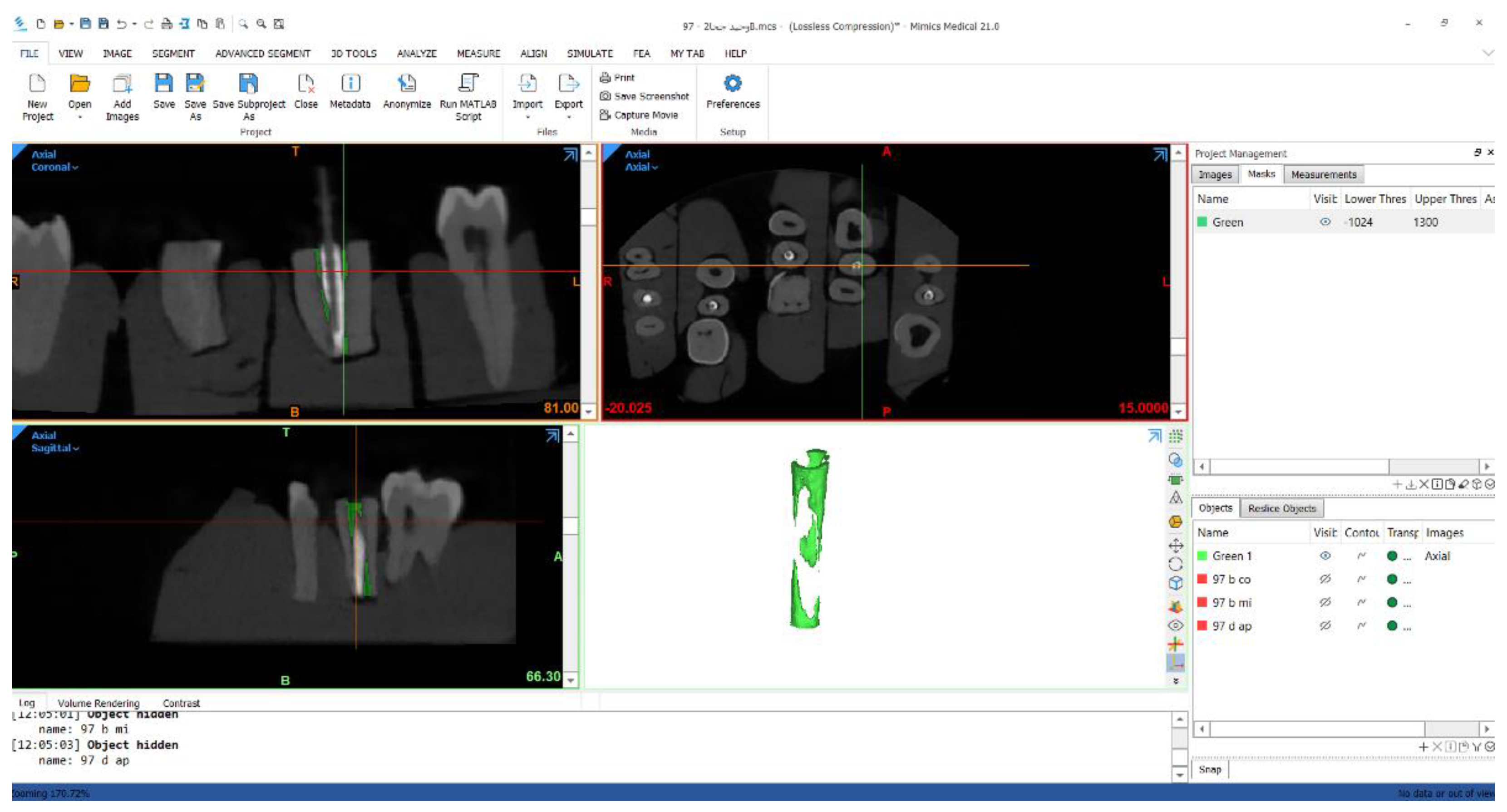
Baseline CBCT scans of all ten empty, prepared canals were acquired (PHT-6500; Vatech), and the total canal volume was segmented in Mimics Research (v21.0.0.406) using the CBCT canal-impression procedure described in Technique C. After the inlays produced by each technique were seated, the roots were re-scanned using the same CBCT protocol, and the residual void volume around each inlay was segmented at the coronal, middle, and apical thirds (Figure 6). The void percentage was calculated as the residual void volume divided by the corresponding baseline (empty) canal volume.
Although micro-computed tomography (micro-CT) offers superior spatial resolution, CBCT was selected for this volumetric analysis for two reasons: (i) it directly replicates the clinical imaging modality most readily available to practitioners for postoperative assessment, thereby enhancing the translational relevance of the findings; and (ii) the standardized canal volume (mean 14.30 mm³) was sufficiently large relative to the 0.2 mm voxel size to permit reliable segmentation of clinically relevant void spaces.
The specimens were positioned on the CBCT plate in the same reproducible position for every scan at baseline (empty canals) and after seating each technique's inlay, ensuring identical orientation across all scans of a given specimen for accurate volumetric comparison.
Void volumes in every CBCT section of each specimen after Bio-Root inlay insertion were measured jointly by two operators (M.T.A. and N.B.), each with ten years of experience in digital dentistry, who were blinded to the impression and Bio-Root inlay fabrication technique. To assess reliability, the measurements were repeated after a two-week interval, demonstrating excellent test–retest reliability (intraclass correlation coefficient, ICC = 0.92).
Figure 6.
Isolation of the void volume in one specimen using Mimics software.
2.5. Statistical Analysis
Data were analyzed using SPSS (Version 20, IBM SPSS Inc., Chicago, IL, USA). A linear mixed model was fitted with technique, canal level, and their interaction as fixed effects, original canal volume as a covariate, and specimen (tooth) as a random intercept to account for repeated within-specimen measurements. The normality assumption was assessed on the model residuals rather than on the raw observations, since the raw measurements were not independent. The Shapiro–Wilk test on the residuals confirmed that they were approximately normally distributed (W = 0.981, p = 0.34), and inspection of the normal Q–Q plot showed no substantial departures from normality. Because the raw void-percentage data were bounded and non-normally distributed, descriptive comparisons among techniques within each canal level were also examined using the non-parametric Friedman test, followed by pairwise Wilcoxon signed-rank tests with Bonferroni correction. The significance level was set at α = 0.05.
3. Results
Overall, void percentage differed markedly among the four techniques. Technique B produced the lowest mean void percentage, and Technique A the second lowest, whereas the CBCT-based (C) and conventional (D) techniques produced the largest voids. Void percentage also rose steadily from the coronal to the apical third, with the apex showing roughly twice the void of the coronal region (Table 1, Figure 7).
This apico-coronal pattern held across all techniques but varied in magnitude (Table 2). Coronally, all four techniques performed similarly well. In the middle third, voids increased across the board, with Technique A showing the lowest void percentage. The techniques diverged most at the apex: Technique B maintained superior apical adaptation, Technique A deteriorated markedly, and Techniques C and D showed the largest apical voids.

Table 2.
Void percentage (mean ± SD) by technique at each root canal third and overall.
| Root canal third | Technique A | Technique B | Technique C | Technique D |
|---|---|---|---|---|
| Coronal | 5.10 ± 3.75 | 5.00 ± 1.83 | 7.20 ± 2.53 | 8.20 ± 4.16 |
| Middle | 7.70 ± 2.98 | 9.80 ± 5.16 | 12.20 ± 6.49 | 14.70 ± 8.39 |
| Apical | 15.20 ± 6.68 | 8.30 ± 6.11 | 21.80 ± 4.49 | 21.60 ± 8.03 |
| Overall | 9.52 ± 5.77 | 7.95 ± 4.41 | 13.82 ± 6.93 | 14.97 ± 8.45 |
Figure 7.
Void-percentage values across root canal thirds for each technique.
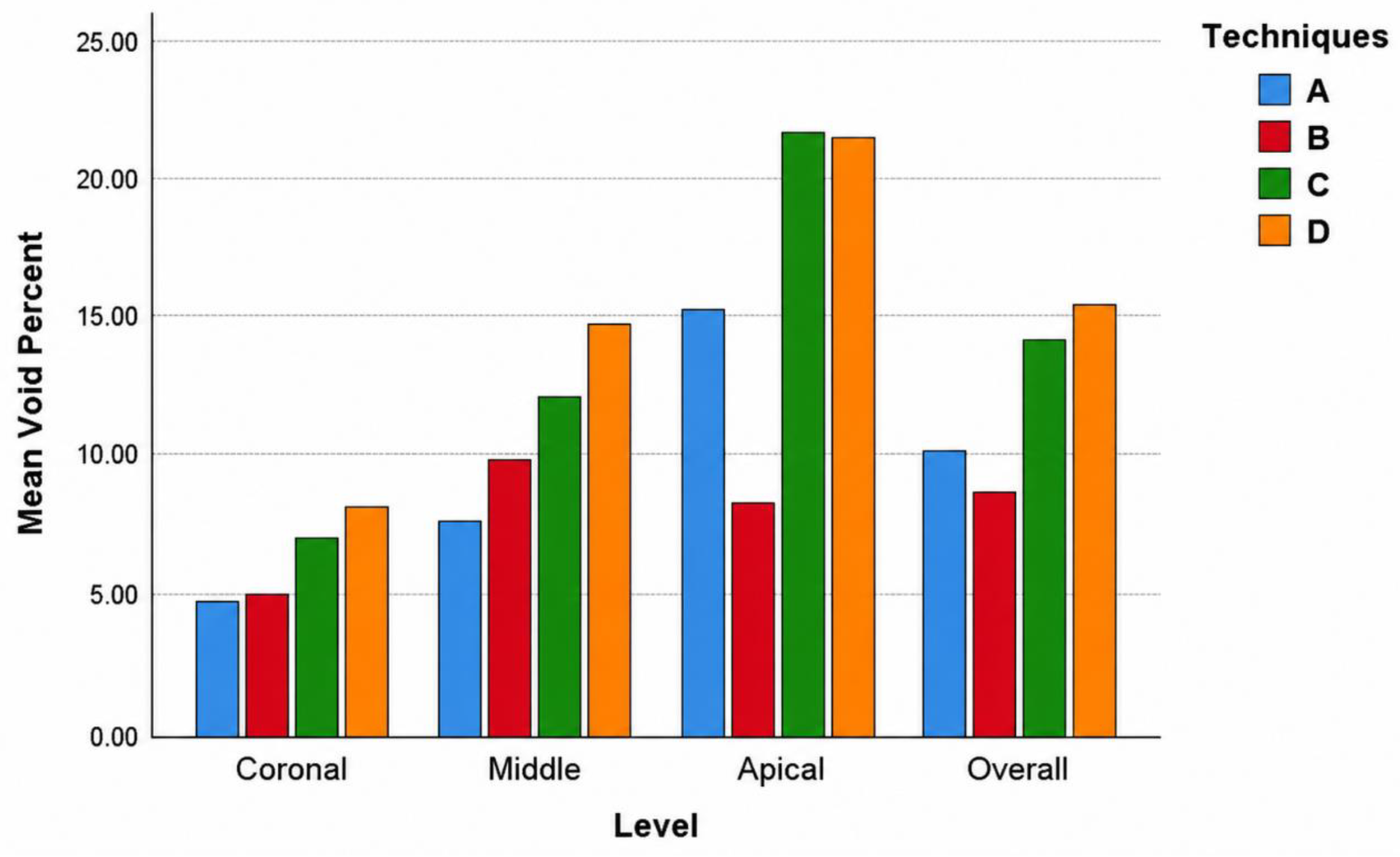
The Friedman test confirmed these observations (Table 3). Differences among techniques were non-significant coronally (p = 0.437) but significant in the middle (p = 0.014) and, most strongly, in the apical third (p < 0.001), as well as overall (p = 0.001).
Wilcoxon signed-rank test with Bonferroni correction (α = 0.0083) (Table 4) localized significant differences to the apical third and, in the overall analysis, chiefly separated the digital techniques (A and B) from the CBCT-based technique C and Technique B from Technique D apically.
A linear mixed model was fitted with technique, canal level, and their interaction as fixed effects, original canal volume as a covariate, and specimen (tooth) as a random intercept to account for repeated within- specimen measurements (Table 5). The model with a technique × canal level interaction showed a significant interaction (F(6, 98) = 3. 67, P = 0. 003), indicating that the impression technique' s effect on void percentage varied by canal level rather than being uniform along the canal. Given this significant interaction, the main effect of technique should not be interpreted in isolation; instead, techniques were compared within each canal level (Table 2, Table 3 and Table 4). This statistically confirms the study' s central observation: the four techniques performed almost identically in the coronal third but diverged progressively toward the apex, where Technique B retained excellent adaptation while the CBCT- based and conventional techniques deteriorated markedly. The interaction therefore formally validates the apex as the region where the choice of impression technique matters most. Canal level itself had a significant effect (F(2, 98) = 5. 82, p = 0. 004), consistent with the apico- coronal increase in voids, whereas the original canal volume had no independent effect once canal level was accounted for (F(1, 98) = 0. 01, p = 0. 923), indicating that the apparent influence of canal size was attributable to canal level rather than to volume per se. The random specimen intercept accounted for a small share of the residual variability (specimen variance = 1. 59; residual = 23. 23.70), and the ranking of the techniques remained consistent across specimens. The mean canal volume was 14. 30 ± 6. 82 mm ³ (range, 6. 6.2–31. 0). Because volume was entered uncentered, the intercept (8. 41%) corresponds to a canal volume of zero and serves only as the model baseline; centering volume at its mean would rescale the intercept to the void percentage expected for Technique A in the coronal third at the average canal volume.
4. Discussion
Digital workflows have transformed multiple domains of dentistry, including guided implant placement, endodontic microsurgery, guided negotiation of calcified canals, and post-and-core fabrication. Their principal advantages, including reduced treatment time, simplified procedures, and improved patient comfort, have been repeatedly documented [17,18]. The present study extended this concept to apexification by, for the first time, evaluating the three-dimensional adaptation of prefabricated Bio-Root inlays fabricated through four different impression pathways. The null hypothesis, which stated that all methods would yield comparable adaptation, was rejected.
A light-body rubber impression, subsequently digitized with an intraoral scanner, produced the lowest mean void percentage, followed by the direct intraoral scan. By contrast, the CBCT-designed and fully conventional inlays showed the poorest adaptation. This gradient indicates that capturing canal geometry via an optical surface (whether directly or via a physical replica) reproduces the internal anatomy of the immature canal more faithfully than volumetric radiographic segmentation or purely analog molding.
Although CBCT was used both as the image source for Technique C and as the outcome assessment tool, the two applications were fundamentally different. CBCT served as the imaging modality during model fabrication, whereas adaptation was quantified by independent segmentation of the residual void volume after inlay placement, with assessment performed in a blinded manner. Nevertheless, the inherent voxel-size limitation of CBCT should be acknowledged as a potential source of measurement uncertainty.
A consistent and clinically important finding was apico-coronal deterioration in adaptation across all techniques: void percentage rose from 6.73% coronally to 11.10% in the middle third and 16.72% apically. No significant differences emerged among the four techniques in the coronal third, where access and light penetration are unrestricted, but significant differences appeared in the middle and, most markedly, the apical third. The apex therefore remained the critical determinant of overall performance, consistent with the anatomical challenge of adapting any material to the widest, least accessible portion of an immature canal. This apex-dependent divergence was formally confirmed by the significant technique × canal level interaction in the mixed model (F(6,98) = 3.67, P = 0.003), which establishes that the superiority of a given impression technique is conditional on canal region rather than uniform along the root.
Beyond resolution limits, an important methodological caveat must be acknowledged: CBCT served dual roles, both as the source image for designing Technique C and as the imaging modality for assessing the outcome. Although these were fundamentally different processes—segmentation of the canal space for design versus segmentation of the residual void for assessment—and were conducted independently by blinded operators, the shared imaging platform could theoretically introduce a systematic bias. Specifically, inherent CBCT thresholding errors might affect both the fabricated inlay and the void measurement in the same direction. Future studies employing micro-CT as the gold-standard reference for outcome assessment are warranted to validate these findings.
The two digital techniques diverged sharply at the apex. Technique A, highly accurate coronally and in the middle third, lost precision apically, whereas Technique B retained excellent apical adaptation and was significantly better than both the CBCT and conventional techniques in this region. This divergence is best explained by the optical path of intraoral scanners: the scanner's beam and field of view are progressively obstructed within a narrow, deep canal, so the apical wall is captured incompletely during direct scanning. In contrast, the light-body rubber first flows into and records the apical geometry as a physical replica, which is then digitized under unobstructed external conditions, effectively decoupling anatomical capture from the optical limitations of intracanal scanning. This interpretation aligns with previous evidence that the accuracy of direct intraoral scanning of post spaces is acceptable only up to a limited depth and decreases as the prepared length increases [8].
The comparatively poor performance of the CBCT-based technique may be attributable to the intrinsic resolution of volumetric imaging. Even at a 0.2 mm voxel size, partial-volume averaging and Hounsfield-unit thresholding introduce boundary uncertainty at the fine, tapering apical walls, so the segmented cavity deviates from true canal morphology more than an optical surface scan. Although CBCT has proven valuable in improving endodontic practice, its voxel-limited spatial resolution appears insufficient for the sub-millimeter fit required of a prefabricated apical inlay. The conventional technique showed the greatest voids overall, reflecting the accumulation of dimensional error inherent in a fully analog, multi-step molding sequence performed without digital refinement of undercuts and internal irregularities. In particular, seating the light-body rubber impression into the heavy-body putty block may itself distort the soft impression, introducing dimensional inaccuracies that are subsequently transferred to the final inlay.
The latter is a robust finding: the ranking and effect of the impression technique remained consistent across teeth with differing morphology, strengthening the generalizability of the observed differences. Canal volume showed a non-significant trend toward influencing void percentage, indicating that the technique itself (rather than canal size) was the dominant driver of adaptation.
These findings should be interpreted in the context of the broader digital-versus-conventional debate. In full-arch implant impressions, conventional techniques have been reported to outperform digital ones; yet in the confined, single-canal geometry examined here, digital surface capture proved superior. This contrast underscores that the accuracy of any impression modality is context-dependent, governed by the accessibility and scale of the anatomy recorded. For the immature canal specifically, a digitized physical impression offers a practical compromise that combines the apical fidelity of a flowable material with the design flexibility of a digital workflow.
Clinically, the results suggest that a digitized soft-rubber impression is currently the most reliable method for fabricating well-adapted prefabricated Bio-Root inlays, particularly when apical sealing is paramount. Direct intraoral scanning remains an attractive, chairside-efficient alternative for the coronal and middle thirds but may require adjunctive strategies to overcome its apical limitations.
From a clinical standpoint, a certain proportion of voids at the inlay–canal interface appears unavoidable regardless of the impression technique. In practice, the prefabricated Bio-Root inlay is seated with a bioceramic sealer from the same material family, which fills residual voids and ensures a continuous, homogeneous interface with comparable physicochemical and biological behavior. Nevertheless, the sealer film should always be kept as thin as possible: the inlay is designed to occupy the bulk of the canal space, while the sealer serves only to obturate the small, unavoidable gaps, since bond strength and dimensional stability are generally more favorable with a thin sealer layer than with a thick one.
To contextualize the present data: for an average canal volume of 14.30 mm³, a 16.72% apical void (the mean observed in the poorest-performing groups) corresponds to approximately 2.4 mm³ of residual space. This volume is readily accommodated by a flowable bioceramic sealer; however, a sealer film of this thickness (roughly 100–200 µm circumferentially) approaches the upper limit recommended for optimal dimensional stability and bond strength. Thus, while Technique B's apical void of 8.30% (approx. 1.2 mm³) offers a superior safety margin, the clinical significance of the absolute difference between techniques warrants further investigation through long-term leakage or push-out bond strength studies.
The main limitation of this study was that it was an in vitro study using standardized, artificially created immature canals in extracted mature premolars, which cannot fully replicate the irregular anatomy, moisture, and blood contamination of the clinical immature apex. Void percentage was assessed by CBCT, whose resolution imposes a measurement floor on the smallest detectable voids; higher-resolution micro-CT could refine future quantification. The crossover design controlled for inter-tooth variability but did not evaluate long-term sealing, push-out bond strength, or clinical outcomes.
Future research should validate these workflows on anatomically variable, immature natural teeth, incorporate micro-CT or fluid-filtration sealing assessments, and explore hybrid capture strategies, such as combining an apical rubber replica with a coronal direct scan, to maximize adaptation throughout the canal. Specifically, we propose that subsequent investigations use high-resolution micro-CT (voxel size ≤ 20 µm) to directly compare the volumetric accuracy of the digitized impression (Technique B) with that of the direct intraoral scan (Technique A), with a particular focus on quantifying the exact apical depth at which direct optical scanning loses fidelity.
5. Conclusion
Within the limitations of this controlled in vitro study, the impression method significantly affected the three-dimensional adaptation of prefabricated Bio-Root inlays in simulated immature roots. Digital surface-capture pathways outperformed both CBCT-based design and the conventional technique, and adaptation deteriorated progressively toward the apex. A light-body rubber impression digitized with an intraoral scanner provided the best overall and apical adaptation, suggesting it may be the most promising approach for a digital apexification workflow. Direct intraoral scanning offered excellent coronal and middle-third fit but reduced apical accuracy.
Declarations
Author Contributions
Y.A.T. and M.T.A. conceptualized the idea, performed the laboratory work, and contributed to writing, documentation, data interpretation, and revision, formatting, and reediting of the manuscript; M.K.A. and W.J. provided exocad processing and digital design; N.B., O.A., and J.A.N. conceptualized the idea and supervised the research. Z.D.B. led the scientific framing, critical revision, and editorial refinement of the manuscript; ensured methodological and ethical compliance; maintained the continuity and integrity of the study from conception to publication; and provided senior mentorship that enhanced its analytical depth and overall presentation. All authors have read and agreed to the published version of the manuscript.
Funding
This work was funded by Damascus University (Grant No. 501100020595).
Ethical: approval
Damascus University Local Research Ethics Committee (Approval No. UDDS-361-13032023/SRC-2654).
Institutional Review Board Statement
The study was conducted in accordance with the Declaration of Helsinki guidelines and approved by the Institutional Review Board of Damascus University (UDDS-361-13032023/SRC-2654).
Informed Consent Statement
Informed consent was obtained from all subjects and caregivers involved in the study.
Data Availability Statement
De-identified data are available upon reasonable request from the corresponding author.
Conflict: of interest
The authors declare no conflicts of interest.
References
- Torabinejad M, Parirokh M. Mineral trioxide aggregate: a comprehensive literature review--part II: leakage and biocompatibility investigations. J Endod. 2010;36(2):190-202. [CrossRef]
- Alsayed Tolibah Y, Bshara N, Aljabban O, Abbara MT, Alhaji M, Almasri IA, et al. Randomized Trial of Bioceramic Apical Barrier Methods in Necrotic Immature Incisors: Effects on Pain, Extrusion, and Procedure Duration. Children (Basel). 2025;12(10). [CrossRef]
- Prati C, Gandolfi MG. Calcium silicate bioactive cements: Biological perspectives and clinical applications. Dent Mater. 2015;31(4):351-70. [CrossRef]
- Tolibah YA, Droubi L, Alkurdi S, Abbara MT, Bshara N, Lazkani T, et al. Evaluation of a Novel Tool for Apical Plug Formation during Apexification of Immature Teeth. Int J Environ Res Public Health. 2022;19(9). [CrossRef]
- Rosaline H, Rajan M, Deivanayagam K, Reddy SY. BioRoot inlay: An innovative technique in teeth with wide open apex. Indian J Dent Res. 2018;29(4):521-4. [CrossRef]
- Thiyagarajan G, Manoharan M, Veerabadhran MM, Murugesan G, Vinodh S, Kamatchi M. Biodentine as BioRoot Inlay: A Case Report. Int J Clin Pediatr Dent. 2023;16(2):400-4. [CrossRef]
- Alsayed Tolibah Y, Awad MK, Najjar YM, Abbara MT, Almonakel MB, Abou Nassar J, et al. Effects of Different Cementation Systems on Pull-out Bond Strength of Fibre Post to Bioceramic Putty Using a 3D Prefabricated Root Canal Model of Immature Permanent Teeth: An In-Vitro Study. Eur Endod J. 2025;10(1):47-57.
- Almalki A, Conejo J, Kutkut N, Blatz M, Hai Q, Anadioti E. Evaluation of the accuracy of direct intraoral scanner impressions for digital post and core in various post lengths: An in-vitro study. J Esthet Restor Dent. 2024;36(4):673-9. [CrossRef]
- Dupagne L, Mawussi B, Tapie L, Lebon N. Comparison of the measurement error of optical impressions obtained with four intraoral and one extra-oral dental scanners of post and core preparations. Heliyon. 2023;9(2):e13235. [CrossRef]
- Tchorz JP, Gierl V, Piasecki L, Frank W, Wrbas KT. Effects of CBCT acquisition protocol and additional superimposed computerized optical impressions on the accuracy of root canal length measurements: an ex vivo study. Int J Comput Dent. 2023;26(2):117-24. [CrossRef]
- Mohamed RH, Abdelrahman AM, Sharaf AA. Evaluation of rotary file system (Kedo-S-Square) in root canal preparation of primary anterior teeth using cone beam computed tomography (CBCT)-in vitro study. BMC Oral Health. 2022;22(1):13. [CrossRef]
- Fornara R, Pisano M, Salvati G, Malvicini G, Iandolo A, Gaeta C. Management of Calcified Canals with a New Type of Endodontic Static Guide: A Case Report. Dent J (Basel). 2024;12(6). [CrossRef]
- Pouhaër M, Picart G, Baya D, Michelutti P, Dautel A, Pérard M, et al. Design of 3D-printed macro-models for undergraduates' preclinical practice of endodontic access cavities. Eur J Dent Educ. 2022;26(2):347-53. [CrossRef]
- Juha W, Sarkis E, Alsayed Tolibah Y. Three-dimensional assessment of obturation volume in lateral canals after three obturation techniques with bioceramic sealer: an in vitro comparative study. BDJ Open. 2024;10(1):50. [CrossRef]
- Nagendrababu V, Murray PE, Ordinola-Zapata R, Peters OA, Rôças IN, Siqueira JF, Jr., et al. PRILE 2021 guidelines for reporting laboratory studies in Endodontology: A consensus-based development. Int Endod J. 2021;54(9):1482-90. [CrossRef]
- Pandolfo MT, Rover G, Bortoluzzi EA, Teixeira CDS, Rossetto HL, Fernades P, et al. Fracture Resistance of Simulated Immature Teeth Reinforced with Different Mineral Aggregate-Based Materials. Braz Dent J. 2021;32(3):21-31. [CrossRef]
- Joda T, Zarone F, Ferrari M. The complete digital workflow in fixed prosthodontics: a systematic review. BMC Oral Health. 2017;17(1):124. [CrossRef]
- Mangano F, Gandolfi A, Luongo G, Logozzo S. Intraoral scanners in dentistry: a review of the current literature. BMC Oral Health. 2017;17(1):149. [CrossRef]
- Jasim AG, Abo Elezz MG, Altonbary GY, Elsyad MA. Accuracy of digital and conventional implant-level impression techniques for maxillary full-arch screw-retained prosthesis: A crossover randomized trial. Clin Implant Dent Relat Res. 2024;26(4):714-23. [CrossRef]
Figure 1.
The specimen embedded in heavy-body putty rubber and flanked by two adjacent teeth to simulate the intraoral anatomical situation. (A) Photographic view; (B) Periapical radiograph.
Figure 1.
The specimen embedded in heavy-body putty rubber and flanked by two adjacent teeth to simulate the intraoral anatomical situation. (A) Photographic view; (B) Periapical radiograph.
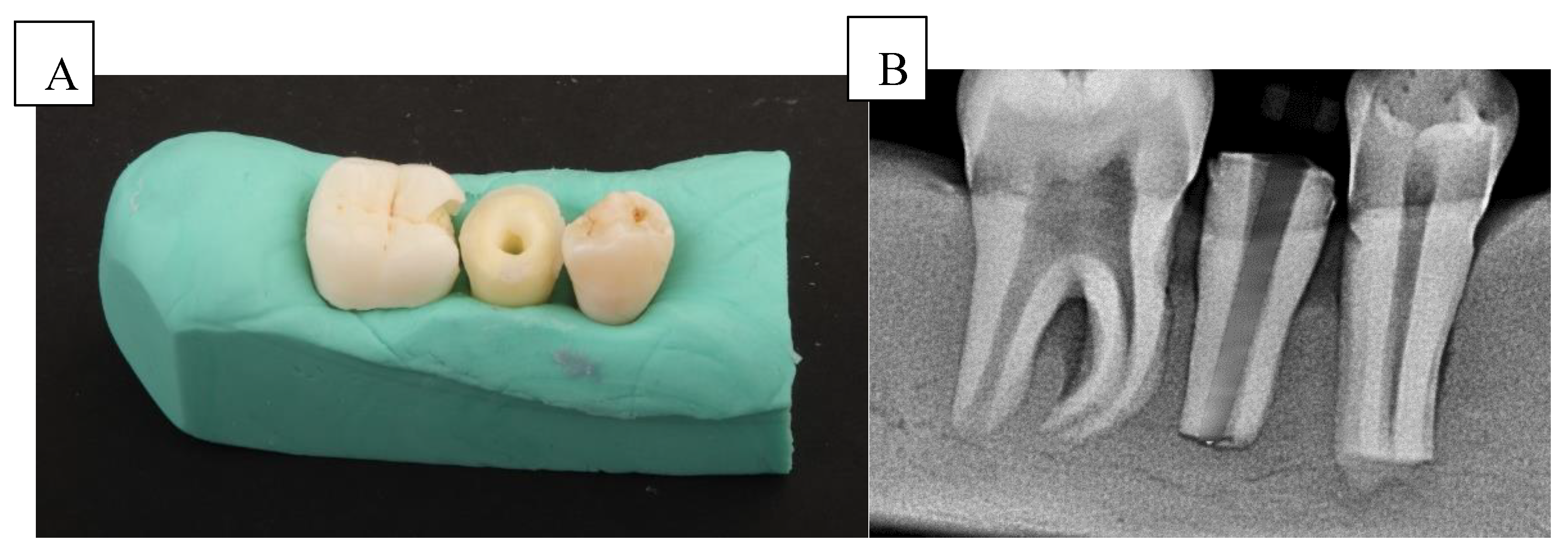
Figure 2.
Three-dimensional surface obtained with the intraoral scanner from the immature canal impression. (A) Occlusal (top) view; (B) Lateral (side) view; (C) Apical (bottom) view.
Figure 2.
Three-dimensional surface obtained with the intraoral scanner from the immature canal impression. (A) Occlusal (top) view; (B) Lateral (side) view; (C) Apical (bottom) view.
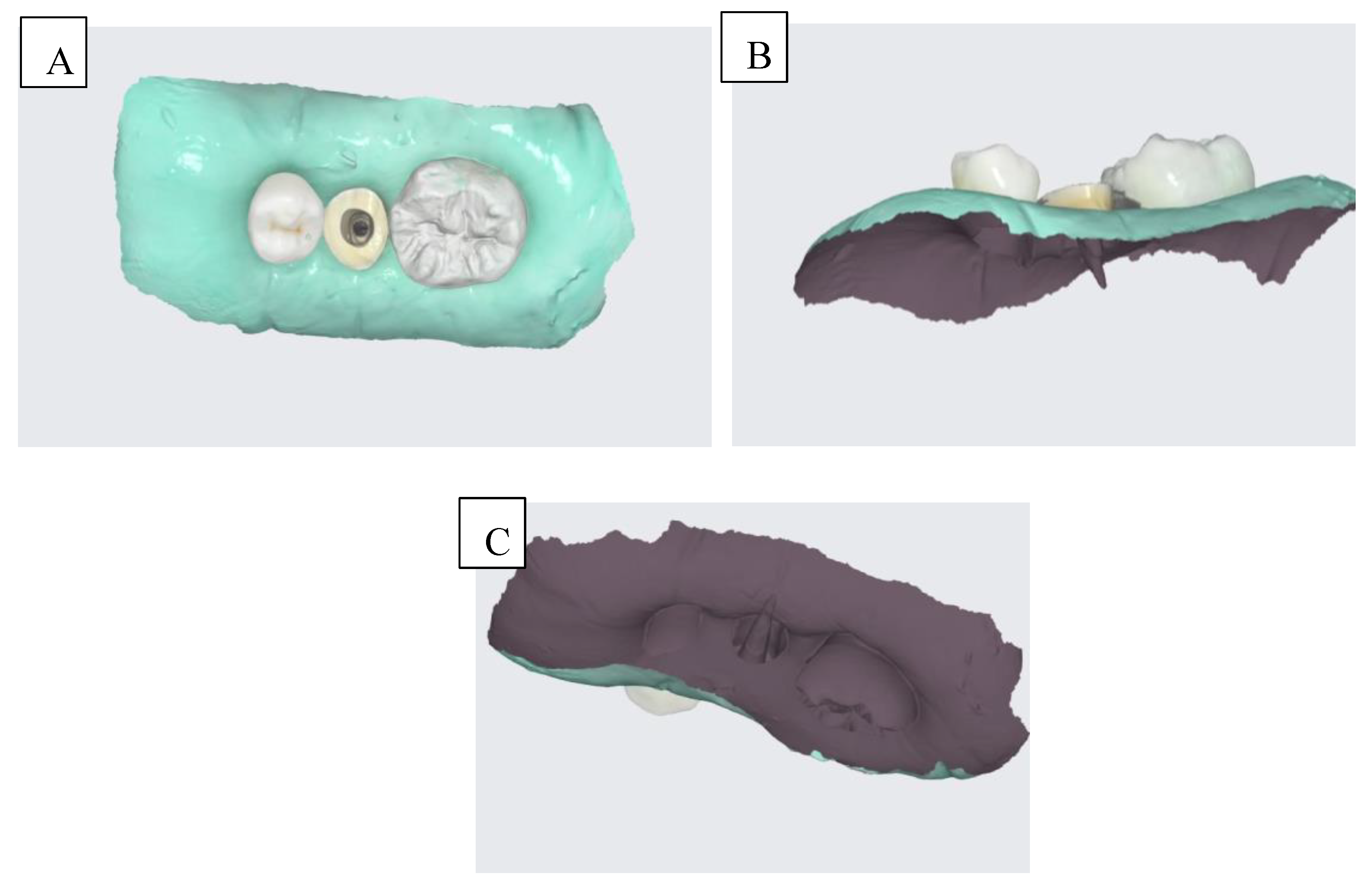
Figure 3.
Three-dimensional model of the light-body silicone impression of the root canal, obtained after digital scanning.
Figure 3.
Three-dimensional model of the light-body silicone impression of the root canal, obtained after digital scanning.
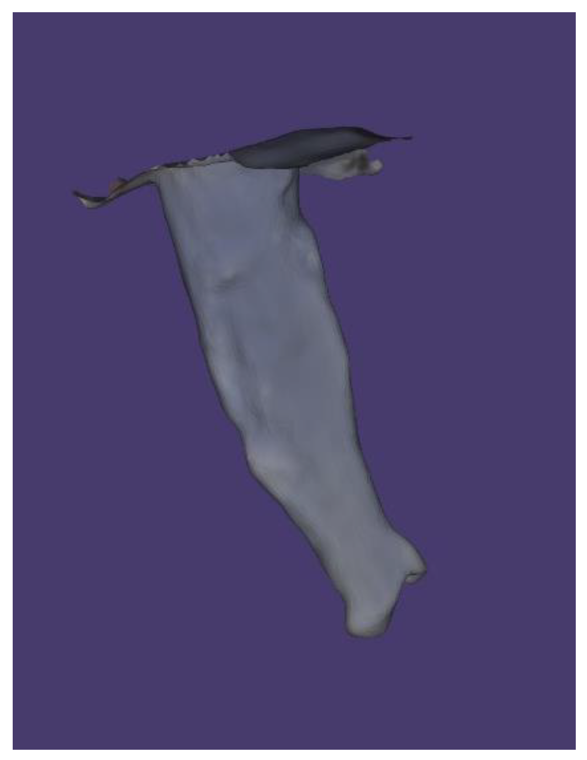
Figure 4.
Three-dimensional model of the root canal after CBCT segmentation using Mimics Software.
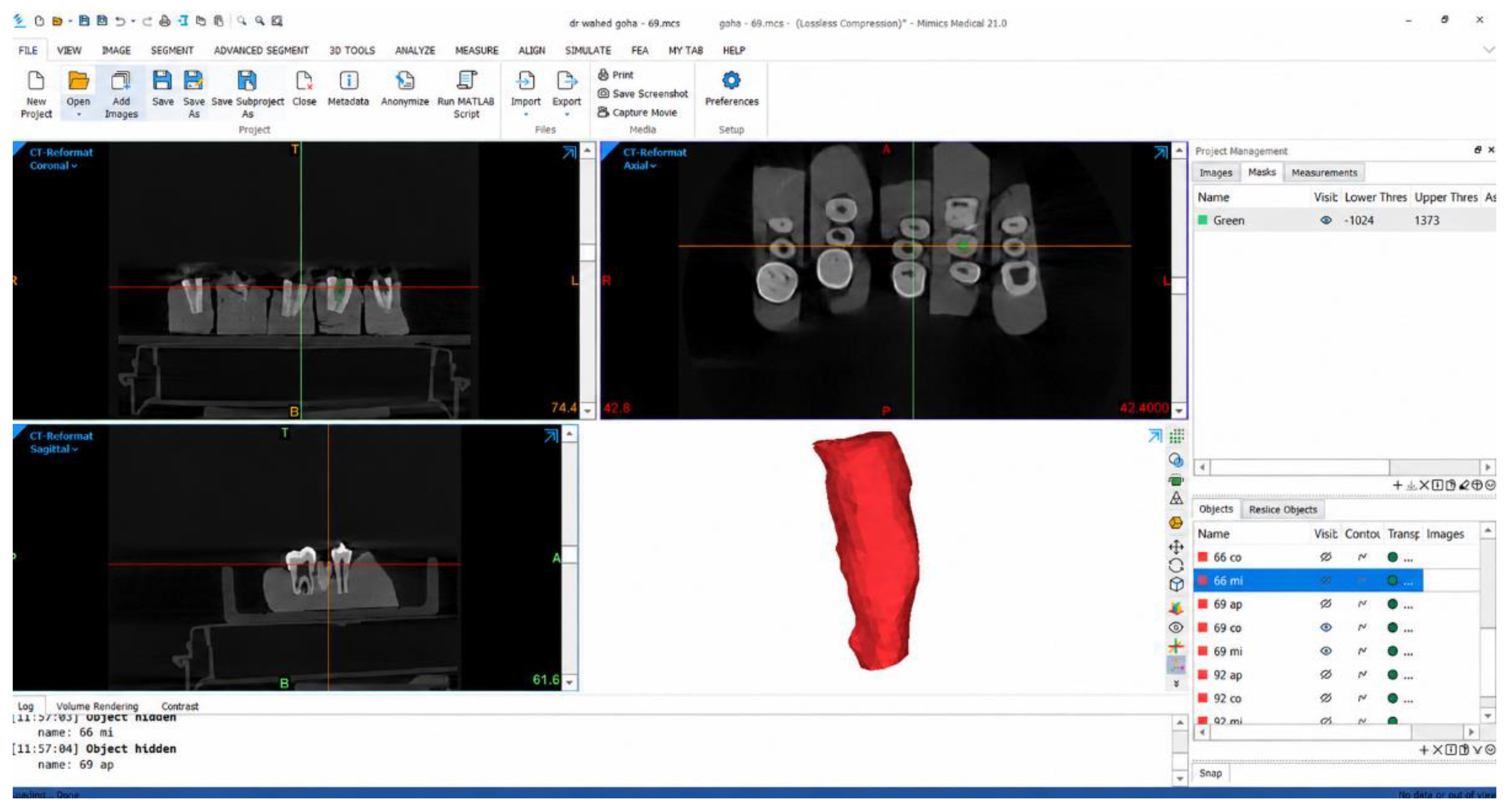
Figure 5.
Conversion of the digital impression into an inverse mold model in Blender.
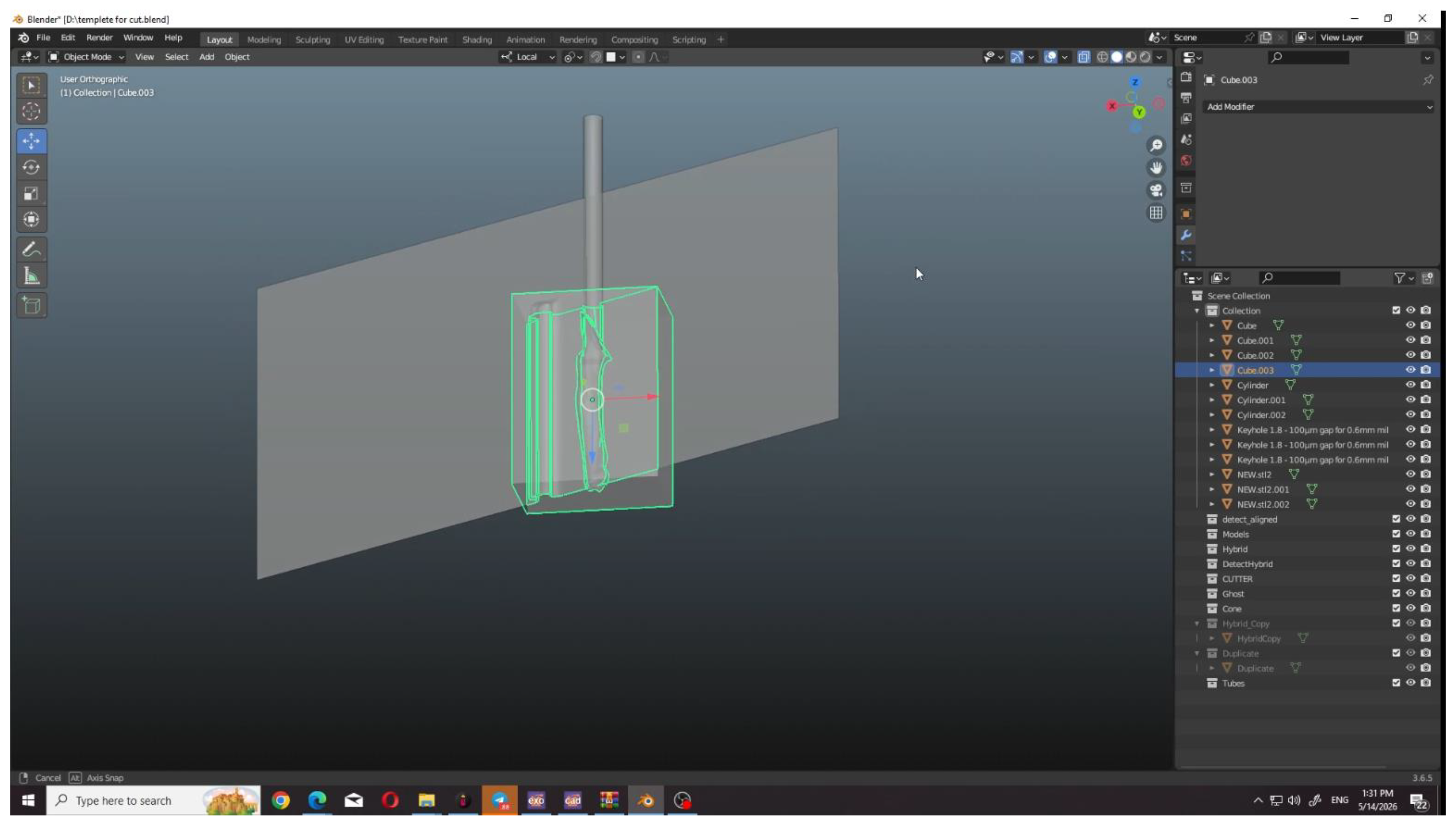
Table 1.
Mean ± standard deviation and median of void-percentage values across techniques and root canal thirds.
Table 1.
Mean ± standard deviation and median of void-percentage values across techniques and root canal thirds.
| Variable | Group | Mean | Std. Dev. | 95% CI | Median |
|---|---|---|---|---|---|
| Techniques | A | 9.52 | 5.77 | 6.97, 11.69 | 8.00 |
| B | 7.95 | 4.41 | 5.83, 9.57 | 6.00 | |
| C | 13.82 | 6.93 | 10.86, 16.61 | 12.00 | |
| D | 14.97 | 8.45 | 11.53, 18.14 | 12.00 | |
| Root canal thirds | Coronal | 6.73 | 3.38 | 5.29, 7.46 | 6.00 |
| Middle | 11.10 | 6.42 | 9.05, 13.15 | 11.00 | |
| Apical | 16.72 | 8.36 | 14.05, 19.40 | 19.00 |
Table 3.
Comparison of void percentage by technique at each root canal third and overall (Friedman test).
Table 3.
Comparison of void percentage by technique at each root canal third and overall (Friedman test).
| Level | Technique | Median (IQR) | χ² | Degrees of freedom | p-value | Decision |
|---|---|---|---|---|---|---|
| Coronal | A | 3.00 (3.00) | 1.29 | 3 | 0.732 | Not significant |
| B | 5.00 (1.00) | |||||
| C | 7.50 (4.00) | |||||
| D | 8.00 (6.25) | |||||
| Middle | A | 8.00 (2.00) | 10.26 | 3 | 0.016 | Significant |
| B | 11.00 (6.50) | |||||
| C | 12.00 (8.25) | |||||
| D | 12.00 (14.75) | |||||
| Apical | A | 18.00 (7.75) | 19.77 | 3 | <0.001 | Significant |
| B | 4.50 (10.00) | |||||
| C | 20.00 (2.75) | |||||
| D | 26.00 (7.00) | |||||
| Overall | A | 8.00 (8.75) | 19.23 | 3 | <0.001 | Significant |
| B | 6.00 (7.00) | |||||
| C | 12.00 (12.50) | |||||
| D | 12.00 (19.00) |
Table 4.
Wilcoxon signed-rank post hoc comparisons of void percentage by technique (Bonferroni-corrected, α = 0.0083).
Table 4.
Wilcoxon signed-rank post hoc comparisons of void percentage by technique (Bonferroni-corrected, α = 0.0083).
| Level | Comparison | p-value | Decision |
|---|---|---|---|
| Middle | A vs B | 0.385 | Not significant |
| A vs C | 0.012 | Not significant | |
| A vs D | 0.015 | Not significant | |
| B vs C | 0.859 | Not significant | |
| B vs D | 0.072 | Not significant | |
| C vs D | 0.205 | Not significant | |
| Apical | A vs B | 0.025 | Not significant |
| A vs C | 0.007 | Significant | |
| A vs D | 0.021 | Not significant | |
| B vs C | 0.007 | Significant | |
| B vs D | 0.007 | Significant | |
| C vs D | 1.000 | Not significant | |
| Overall | A vs B | 0.330 | Not significant |
| A vs C | 0.004 | Significant | |
| A vs D | 0.021 | Not significant | |
| B vs C | 0.007 | Significant | |
| B vs D | 0.013 | Not significant | |
| C vs D | 0.959 | Not significant |
Table 5.
Linear mixed-model analysis of void percentage (technique and canal levels as fixed effects, canal volume as a covariate, and specimen as a random intercept).
Table 5.
Linear mixed-model analysis of void percentage (technique and canal levels as fixed effects, canal volume as a covariate, and specimen as a random intercept).
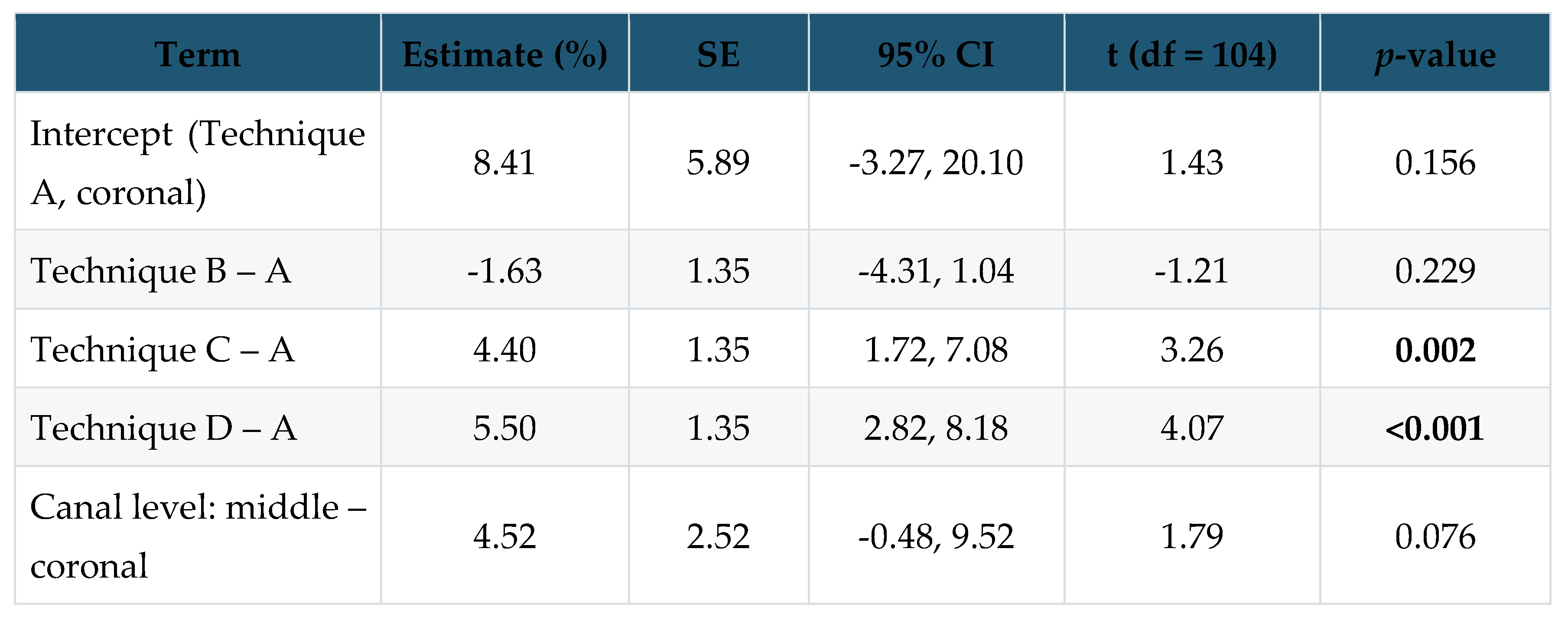
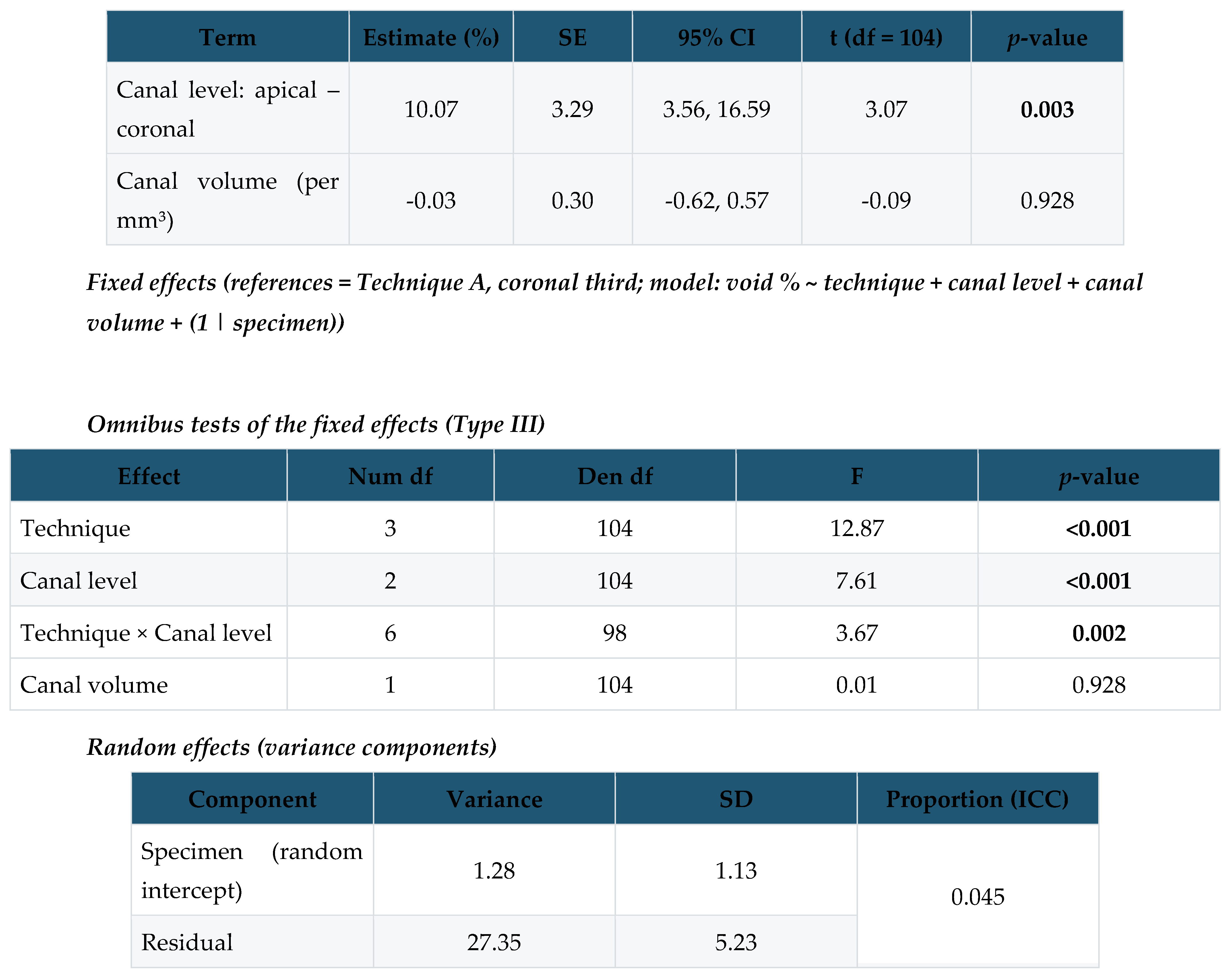
Dependent variable: void percentage (%). Technique, canal level and their interaction were modelled as fixed effects, original canal volume as a covariate, and specimen (tooth) as a random intercept. The significant technique × canal level interaction (F(6,98) = 3.67, P = 0.002) indicates that the effect of technique on void percentage depended on the canal third; consequently the technique main effect is not interpreted in isolation and the techniques were compared within each level (Table 2, Table 3 and Table 4). Canal volume had no independent effect after adjustment for canal level (P = 0.923). Fixed-effect denominator degrees of freedom were obtained by the containment method. The specimen random intercept accounted for only 4.5% of the total variance (ICC = 0.045), indicating minimal variation attributable to inter-tooth anatomical differences once technique and canal level were accounted for.
Disclaimer/Publisher’s Note: The statements, opinions and data contained in all publications are solely those of the individual author(s) and contributor(s) and not of MDPI and/or the editor(s). MDPI and/or the editor(s) disclaim responsibility for any injury to people or property resulting from any ideas, methods, instructions or products referred to in the content. |
© 2026 by the authors. Licensee MDPI, Basel, Switzerland. This article is an open access article distributed under the terms and conditions of the Creative Commons Attribution (CC BY) license (http://creativecommons.org/licenses/by/4.0/).
Copyright: This open access article is published under a Creative Commons CC BY 4.0 license, which permit the free download, distribution, and reuse, provided that the author and preprint are cited in any reuse.