
Submitted:
17 July 2026
Posted:
17 July 2026
You are already at the latest version
Abstract
Advanced Driver Assistance Systems (ADAS) rely on tightly integrated sensing, estimation, and control pipelines to enhance road safety while maintaining the human driver in the control loop. This paper presents a unified, reproducible modeling and evaluation framework for four widely deployed ADAS functions—Lane Keeping Assist (LKA), Forward Collision Warning (FCW), Blind Spot Detection (BSD), and Automated Parking Assist. For each function, we detail the sensing architecture, governing mathematical models, decision and control logic, and representative validation criteria drawn from industrial practice. The models include a kinematic bicycle formulation for lateral control, constant‑velocity and constant‑acceleration time‑to‑collision kinematics for collision‑risk estimation, polygonal zone geometry for radar‑based blind‑spot monitoring, and a two‑arc geometric construction for parking path planning. Reference Python implementations and simulation results are provided, demonstrating RMS lateral offset of 0.29 m for LKA, FCW alert latency of 50 ms, BSD zone dwell accuracy within 0.5 s, and automated parking maneuver time of 4.83 s. A Monte‑Carlo sensitivity analysis of FCW thresholds illustrates the trade‑off between early warning and nuisance‑alert rate that governs production calibration. The unified treatment offered here provides a consolidated reference for researchers and engineers developing or evaluating ADAS sensing‑to‑actuation pipelines.
Keywords:
Advanced Driver Assistance Systems
; Lane Keeping Assist
; Stanley controller
; Forward Collision Warning
; time‑to‑collision
; Blind Spot Detection
; Automated Parking Assist
; vehicle dynamics
; path planning
; sensor fusion
; FMCW radar
; CFAR detection
; kinematic bicycle model
; Electric Power Steering
; Monte‑Carlo simulation
; ADAS validation
; trajectory tracking
; geometric path planning
; autonomous driving
1. Introduction
Advanced Driver Assistance Systems (ADAS) form the technological foundation for higher levels of vehicle automation. Modern ADAS functions augment human perception and reaction capability by continuously monitoring vehicle state and surroundings, and intervening—through warnings or corrective actuation—when hazards or deviations are detected. As regulatory bodies such as Euro NCAP, NHTSA, and ISO 15623/17387 increasingly standardize ADAS performance requirements, the need for reproducible modeling frameworks has grown substantially.
Despite the maturity of ADAS deployment, public-facing descriptions of these functions often remain qualitative, emphasizing conceptual behavior rather than the quantitative models, control laws, and calibration trade-offs used in engineering practice. Existing literature typically treats ADAS functions individually—lane keeping, collision warning, blind-spot monitoring, or parking assist—without presenting a unified sensing-to-actuation architecture that spans multiple functions. This fragmentation limits the ability to compare functions, evaluate cross-cutting design trade-offs, or reuse modeling components across systems.
This paper addresses that gap by presenting a unified modeling and evaluation framework for four representative ADAS functions: Lane Keeping Assist (LKA), Forward Collision Warning (FCW), Blind Spot Detection (BSD), and Automated Parking Assist. For each function, we provide:
- (i)
- a detailed sensing architecture and system block diagram;
- (ii)
- governing mathematical models expressed in embedded-implementation form;
- (iii)
- reference Python implementations suitable for reuse;
- (iv)
- simulation-based performance results; and
representative acceptance criteria drawn from industrial validation practice. The unified treatment enables consistent comparison across functions and highlights shared architectural patterns in perception, decision logic, and actuation.
2. System Architecture Overview
Although LKA, FCW, BSD, and Automated Parking Assist differ in sensing modality and control objective, each function follows a common sensing-to-actuation pipeline: sensing, state estimation and sensor fusion, decision logic, actuation or driver alerting, and closed-loop feedback. This unified abstraction enables consistent modeling across functions and highlights shared design constraints.
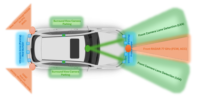
The vehicle sensor suite supporting these functions includes a front-facing camera and 77 GHz radar for lane geometry and forward-object tracking, rear corner 24 GHz radars for blind-spot monitoring, and an array of ultrasonic sensors and surround-view cameras for parking assist. Sensor fusion aligns radar and camera detections in a common coordinate frame, compensates for ego-motion using yaw-rate and speed sensors, and filters noisy measurements using exponential smoothing or Kalman filtering. The fused perception output feeds into decision logic tailored to each function—lateral control for LKA, time-to-collision estimation for FCW, polygonal zone evaluation for BSD, and geometric path planning for parking assist.
A unified block diagram capturing this pipeline—sensing → fusion → decision → actuation—provides a consistent architectural foundation for the modeling and simulation presented in subsequent sections.
Figure 1 summarizes this pattern and shows how each function maps onto the shared vehicle sensor suite.
Figure 2 details the physical sensor layout used to realize this architecture on a representative passenger vehicle. The front-facing camera and 77 GHz radar jointly support both LKA (lane geometry) and FCW (range and range-rate to a leading object); rear corner radars operating at 24 GHz support BSD; and an ultrasonic sensor array combined with surround-view cameras supports Automated Parking Assist.
3. Lane Keeping Assist (LKA)
3.1. Functional Description
Lane Keeping Assist (LKA) is a closed-loop lateral control function designed to maintain the vehicle near the lane centerline during highway driving. The system continuously estimates the vehicle’s lateral offset and heading misalignment relative to the detected lane geometry and commands corrective steering torque through the Electric Power Steering (EPS) actuator. Unlike Lane Departure Warning (LDW), which provides only driver-facing alerts, LKA actively applies steering corrections, requiring robust perception, stable control laws, and careful calibration to ensure smooth and safe operation.
3.2. System Architecture
The LKA function is implemented as a closed-loop lateral control system operating at the camera frame rate (typically 30–60 Hz), as shown in Figure 3. The pipeline begins with the front-facing camera, which detects lane markings and provides lane centerline geometry—position, heading, and curvature—relative to the vehicle. These perception outputs are combined with vehicle-dynamics signals from onboard sensors, including yaw rate, longitudinal speed, and steering angle.
The perception module reports lane-relative quantities such as lateral offset, heading error, and road curvature. These are converted into error states that directly feed the controller. The controller computes a steering command based on these error states and the vehicle speed, and this command is sent to the Electric Power Steering (EPS) system. The EPS applies the corresponding steering torque to the front wheels, changing the vehicle trajectory.
The resulting vehicle motion is measured again by the dynamics sensors (yaw rate, speed, steering angle), and the updated vehicle pose is fed back into the perception and error-state computation at the next cycle. This forms the continuous state-feedback loop highlighted in Figure 3:
Camera → Lane perception → Error-state computation → Controller → EPS actuation → Vehicle response → Vehicle-dynamics feedback → back to perception and controller.
This architecture matches the block diagram in Figure 3 and emphasizes that LKA is a true closed-loop control function, not a purely open-loop warning system.
3.3. Vehicle Dynamics Model
For lateral control at highway speeds, the kinematic bicycle model is the standard simplification adopted in both academic and industrial practice. It reduces the four-wheel vehicle to a two-axle representation and neglects tire slip, an approximation that is valid below approximately 0.4 g lateral acceleration — encompassing essentially all normal LKA operating conditions [1,2]:
where x and y denote vehicle position (m), ψ the heading/yaw angle (rad), v the vehicle speed (m/s), L the wheelbase (m, typically 2.5–2.9 m for a passenger car), and δ the front-wheel steering angle (rad), which serves as the control input.
|
ẋ = v·cos(ψ)
ẏ = v·sin(ψ)
ψ̇ = (v / L)·tan(δ)
|
3.4. Error State Formulation
The controller is not implemented directly in Cartesian coordinates; instead it operates on lane-relative error states, which correspond directly to the output of the lane-detection perception module (edge-based or CNN-based):
|
e_y = (y_vehicle − y_lane) · cos(ψ_lane)
e_ψ = ψ_lane − ψ_vehicle (wrapped to [-π, π])
|
Here e_y is the cross-track (lateral) error — the perpendicular distance from the vehicle reference point to the lane centerline — and e_ψ is the heading error between the vehicle heading and the local lane tangent direction.
3.5. Control Law: Stanley Method
Production LKA systems generally employ either the Stanley controller [3], a geometric control law originally developed for the Stanford autonomous vehicle entry in the DARPA Grand Challenge, or a Model Predictive Controller (MPC) for improved smoothness under actuation constraints. The Stanley law is adopted here for its closed-form simplicity and single tunable gain:
δ_cmd = e_ψ − arctan( k · e_y / v )
|
The gain k trades off correction aggressiveness against ride comfort: small k produces gentle, slower re-centering, while large k produces faster but potentially less comfortable correction, with risk of low-speed oscillation since the 1/v term amplifies the effective gain as speed decreases. This built-in speed dependence mirrors the natural behavior of a human driver, who applies proportionally larger steering input at low speed for the same lateral offset.
A refinement adopted in several production and research implementations augments the feedback law with a curvature feedforward term, using the road curvature κ reported by the perception module ahead of the vehicle [2,3]:
δ_cmd = δ_feedback + δ_feedforward, δ_feedforward = arctan(L · κ)
|
The feedforward term pre-positions the steering angle for an upcoming curve before a cross-track error has had the chance to develop, which reduces peak lateral offset on curve entry relative to a purely reactive feedback law. The lane-detection perception module itself is typically realized with either classical edge- or Hough-transform-based methods, or, in current production systems, a convolutional neural network trained to regress the lane polynomial directly from the camera image; the error-state formulation in Section III-D is agnostic to which of the two is used, provided the perception module reports e_y, e_ψ, and κ at each control cycle.
3.6. Reference Implementation
Algorithm 1 summarizes the reference Python implementation used to generate the results in Section III-G.

3.7. Simulation Results
The controller was evaluated starting from a deliberately large initial condition (1.2 m lateral offset and 5° heading error, representative of a wind gust or momentary distraction) on a curved lane section. Figure 4 shows the resulting vehicle trajectory relative to the lane centerline, and Figure 5 shows the corresponding error signals over time.
Table 1.
Measured LKA Performance.
| Metric | Value |
| RMS lateral offset | 0.29 m |
| Max lateral offset | 1.20 m (initial condition) |
| Settling time (|e_y| < 0.10 m) | 5.62 s |
| Max steering angle commanded | 4.1° |
3.8. Performance and Acceptance Criteria
Table 2 summarizes representative acceptance criteria used in industrial LKA validation plans, mapped to the corresponding test-scenario objective.
The operating envelope is further constrained in the embedded implementation: the function is active only above approximately 60 km/h (configurable), is disabled during hard braking or extreme cornering, and is suppressed for a short interval after the turn signal is engaged to accommodate an intentional lane change. Validation against these criteria is typically conducted following consumer and regulatory test protocols such as the Euro NCAP Lane Support Systems protocol [14].
4. Forward Collision Warning (FCW)
4.1. Functional Description
Forward Collision Warning (FCW) monitors the road ahead using a front-facing radar fused with camera perception to estimate the closing dynamics between the host vehicle and a lead object. The system computes the time remaining before a potential collision at the current closing speed and issues a visual, audio, or haptic warning early enough for the driver to brake or steer. FCW is strictly a warning function; automatic braking, where present, is handled by a separate Autonomous Emergency Braking (AEB) module.
4.2. System Architecture
The FCW pipeline, shown in Figure 6, begins with the front 77 GHz radar, which provides range and range-rate measurements to detected objects. The camera contributes object classification, lane context, and improved range estimation under favorable visibility. Sensor fusion aligns radar and camera detections in a common coordinate frame and filters noisy Doppler measurements using exponential smoothing or Kalman filtering.
The fused perception output provides:
- Range to the lead vehicle
- Relative speed
- Optional relative acceleration
These quantities feed the TTC computation block. The decision logic compares TTC against a calibrated threshold and triggers a warning when the threshold is crossed. The driver’s reaction and vehicle response are monitored through the vehicle-dynamics sensors, closing the loop illustrated in Figure 6.
4.3. Time-to-Collision Model
The primary risk metric used in FCW is the constant-velocity Time-to-Collision:
To improve responsiveness during hard lead-vehicle braking, a constant-acceleration TTC variant is sometimes blended in:
Solving for yields:
Although the constant-velocity TTC is used as the primary alert criterion in this paper, the simulation includes realistic accelerations to ensure representative sensor-noise behavior.
4.4. Decision Logic
if v_rel > v_rel_min: # only evaluate when actually closing
TTC = d / v_rel
if TTC < TTC_threshold:
issue_warning()
The TTC threshold is the most influential calibration parameter in FCW. Production systems typically use thresholds in the range 2.0–2.7 s, balancing early warning against false-alert rate. Adaptive thresholds based on driver-specific braking behavior have been shown to reduce nuisance alerts without compromising safety.
4.5. Reference Implementation

4.6. Simulation Results and Threshold Sensitivity Analysis
The scenario simulated a lead vehicle braking hard (−6 m/s²) at t = 3.0 s, with the host vehicle responding after a realistic 0.5 s driver-model reaction delay at −3 m/s². Figure 7 shows the resulting range, relative speed, and estimated TTC over time.
The FCW alert fires at t = 3.05 s, only 50 ms after the lead vehicle begins braking and well before the host driver's own 0.5 s reaction — illustrating the intended function of buying the driver additional reaction time.
Because TTC_threshold governs both sensitivity and false-alert rate, a 200-trial Monte-Carlo sensitivity analysis was performed over thresholds from 1.0 s to 5.0 s, resampling sensor noise on each trial. Figure 8 and Table 3 report the results.
A false alert is defined as a warning triggered prior to the real braking event at t = 2.5 s, arising purely from sensor noise. Below approximately 3.0 s, the false-alert rate is essentially zero; above 3.25 s, noise in the range-rate estimate alone is sufficient to falsely cross the threshold on nearly every trial. This explains why production calibrations typically operate in the 2.0–2.7 s band, and why filtering of the range-rate estimate (e.g., an alpha-beta or Kalman filter, rather than raw radar Doppler) is as important to overall performance as the threshold value itself.
4.7. Performance and Acceptance Criteria
Table 4.
FCW Validation Test Scenarios and Pass Criteria.
| Test scenario | Objective | Typical pass criteria |
| Stationary lead object | Detect and warn in time to stop | Warning at TTC ≥ threshold, distance error < 0.5 m |
| Decelerating lead vehicle | React to sudden braking | Alert latency < 100 ms from true TTC crossing |
| Cut-in scenario | Detect newly appeared close object | Warning within one detection cycle of object entry |
| False-alert immunity | No nuisance alerts on stationary roadside objects | False-alert rate < 1 per 100 km highway driving |
| Adverse weather | Maintain detection with degraded camera | Radar-only fallback maintains TTC accuracy within ±15% |
5. Blind Spot Detection (BSD)
5.1. Functional Description
Blind Spot Detection (BSD) uses rear corner radars (24 GHz, one per side) to monitor the regions alongside and slightly behind the vehicle that are not visible in the mirrors. When a target vehicle is detected within the calibrated blind-spot zone, a steady LED indicator is illuminated in the corresponding side mirror. If the driver subsequently activates the turn signal toward the occupied lane, the system escalates the alert to an audio or haptic warning [7]. This two-tier alerting strategy minimizes nuisance alerts while providing strong intervention when the risk becomes imminent.
5.2. System Architecture
Production BSD radars are almost universally Frequency-Modulated Continuous-Wave (FMCW) systems [7]. A linear frequency chirp is transmitted and mixed with its own reflection, producing a beat frequency proportional to target range, while Doppler processing across successive chirps yields target relative velocity.
Range and velocity resolution are governed by the chirp bandwidth and chirp duration :
After range-Doppler processing (typically a 2D FFT across fast-time and slow-time samples), a Constant False Alarm Rate (CFAR) detector—commonly CA-CFAR or CA/CGSA-CFAR—adaptively sets the detection threshold against the local noise floor to maintain a bounded false-alarm probability across varying clutter conditions [7].
Detected targets are transformed into vehicle-fixed coordinates and passed to the zone-geometry evaluation block shown in Figure 9.
5.3. Detection Zone Geometry
The BSD detection zone is a calibrated trapezoidal region corresponding to the adjacent-lane blind area. The polygon used in this paper matches the geometry shown in Figure 10:
A detected radar target at position is evaluated using a point-in-polygon test (ray-casting or winding-number method). In embedded implementations, a half-plane test is used due to the polygon’s convexity; in the Python reference implementation, matplotlib. path.Path.contains_point is used
5.4. Alert Decision Logic

This two-tier alerting logic is a deliberate design choice: the steady LED indicator is informational and low-annoyance during routine highway driving, whereas the escalated alert is reserved for the moment at which the risk is acute — when the driver is actively initiating a lane change into an occupied lane.
5.5. Reference Implementation
Your Python implementation (reproduced below) matches the simulation results shown in Figure 10 and Figure 11:

5.6. Simulation Results
A scenario was simulated in which a vehicle overtakes in the adjacent lane while the driver engages the turn signal partway through the maneuver. Figure 10 shows the target trajectory through the detection zone, and Figure 11 shows the corresponding two-tier alert timeline.
Table 5.
Measured BSD Alert Timing.
| Event | Time |
| Target enters BSD zone | t = 3.95 s |
| Target exits BSD zone | t = 5.00 s |
| Zone dwell time | 1.05 s |
| Haptic alert active (zone occupied and signal on) | 0.55 s |
The escalation logic performs as intended: the mirror LED indicator covers the entire 1.05 s dwell time, while the haptic/audio alert fires only during the 0.55 s sub-window in which the target is present and the driver has signaled toward that lane — the interval of actual collision risk.
5.7. Performance and Acceptance Criteria
6. Automated Parking Assist
6.1. Functional Description
Parking Assist functions span a spectrum from simple rear-obstacle alerting to fully automated parking, in which the system controls steering, throttle, brake, and gear selection. The core engineering problem—and the one that generalizes to the semi-automatic Park Assist function most commonly deployed today—is geometric path planning: given a detected free slot, compute a drivable path from the current vehicle pose into the slot, and then track that path. This paper focuses on the semi-automatic implementation, where the system commands steering while the driver manages throttle and brake.
6.2. System Architecture
Figure 12 shows the Parking Assist system block diagram. Slot detection is performed using ultrasonic sensors and surround-view cameras, which jointly estimate the geometry and pose of the available parking space. The perception module outputs the slot boundaries and the vehicle-relative target pose.
The path-planning block computes a feasible trajectory using a geometric construction. The steering-control block converts curvature commands into steering-angle commands for the Electric Power Steering (EPS) actuator. Vehicle-dynamics feedback (speed, yaw rate, steering angle) closes the loop, ensuring the vehicle follows the planned path.
This sensing-to-actuation pipeline matches the block diagram shown in Figure 12.
6.3. Path Planning: Two-Arc Geometric Method
The classical approach to reverse parallel or perpendicular parking, still widely used in production systems, is the two tangent-arc construction [8]. The path from the start pose to the goal pose is composed of two circular arcs of equal radius, steered in opposite directions, joined at a common tangent point.
The minimum turning radius is determined by the bicycle model steering-angle limit:
where is the wheelbase and is the maximum steering angle. For and a calibrated maneuvering radius of , the required steering angle for each arc is constant:
This yields a practical insight: during the two-arc maneuver, the steering angle is held at a fixed magnitude through the first arc, then reversed in sign and held through the second arc—precisely the command sequence used in semi-automatic Park Assist systems.
Limitations and Refinements
The principal limitation of the two-arc construction is the discontinuous curvature at the junction between arcs, which requires an instantaneous steering-angle reversal that a real EPS actuator cannot physically deliver. Three refinements are commonly used in production systems:
The two-arc method is retained here because it is closed-form, requires no iterative solve, and is sufficient to convey the governing turning-radius constraint.
6.4. Reference Implementation
Python implementation below reproduces the planned path and steering-angle profile shown in Figure 13 and Figure 14:

For fully automated systems, this geometric path typically serves only as an initial guess; a downstream optimizer or clothoid/spline smoother refines it into a curvature-continuous trajectory, avoiding the instantaneous steering-angle transition between the two arcs that would otherwise exceed the finite slew rate of a real EPS actuator.
6.5. Simulation Results
A reverse-parking maneuver was planned into a 6.0 m × 2.4 m slot from a start pose offset 1.6 m laterally from the slot centerline. Figure 13 shows the planned path together with the slot geometry, and Figure 14 shows the corresponding required steering-angle profile as a function of distance traveled.
Table 7.
Computed Parking Maneuver Parameters.
| Metric | Value |
| Total path length | 4.83 m |
| Required steering angle (magnitude) | ±28.4° |
| Turning radius used | 5.0 m |
| Estimated maneuver time (1.0 m/s creep speed) | 4.83 s |
6.6. Performance and Acceptance Criteria
7. Cross-Cutting Design Trade-Offs
Although Lane Keeping Assist (LKA), Forward Collision Warning (FCW), Blind Spot Detection (BSD), and Automated Parking Assist differ in sensing modality, control objective, and operational domain, several cross-cutting design trade-offs influence their performance and calibration. These trade-offs arise from shared constraints in sensing, actuation, driver interaction, and functional safety.
Sensor noise versus alert stability: All four functions rely on real-time perception signals that are subject to noise, environmental degradation, and intermittent loss. LKA must filter lane-geometry estimates to avoid oscillatory steering; FCW must suppress Doppler noise to prevent nuisance alerts; BSD must maintain CFAR thresholds across cluttered environments; and Parking Assist must handle ultrasonic reflections from irregular surfaces. Increasing sensitivity improves responsiveness but raises false-alert rate, requiring careful tuning of filters and thresholds.
Control aggressiveness versus ride comfort: LKA and Parking Assist directly actuate steering, making control smoothness essential for driver acceptance. Aggressive gains reduce tracking error but may produce abrupt steering corrections, while conservative gains improve comfort at the cost of slower convergence. MPC-based controllers mitigate this trade-off by explicitly enforcing comfort-related constraints, but at higher computational cost.
Radar versus camera redundancy: FCW and BSD rely primarily on radar for robustness in adverse weather, while LKA and Parking Assist rely heavily on camera-based perception. Radar provides reliable range and velocity estimates but limited semantic understanding; cameras provide rich contextual information but degrade under poor visibility. Fusion strategies must balance these complementary strengths to maintain performance across environmental conditions.
Actuator limits versus path feasibility: EPS steering rate limits constrain the feasible trajectories for LKA and Parking Assist. The two-arc parking path requires instantaneous steering reversal, which exceeds actuator capabilities unless smoothed using clothoids or spline-based transitions. Similarly, LKA must respect steering-rate and torque limits to avoid abrupt or unsafe corrections.
Driver intent versus system intervention: BSD and FCW must interpret driver intent—such as turn-signal activation or braking behavior—to escalate alerts appropriately. LKA must disengage gracefully when the driver overrides steering torque. Parking Assist must ensure that driver throttle/brake inputs do not conflict with steering commands. These interactions require careful HMI design and functional-safety validation under ISO 26262 [13].
These cross-cutting considerations highlight the importance of unified sensing-to-actuation modeling across ADAS functions, enabling consistent calibration, shared perception modules, and harmonized driver-interaction strategies.
8. Discussion
A common architectural pattern emerges across all four functions studied in this paper: sensing, fusion or state estimation, decision logic, actuation or alerting, and closed-loop feedback. This pattern, summarized graphically in Figure 1, is not merely a documentation convention but the actual system decomposition that should guide implementation, whether targeting an embedded ECU in C/C++ or a prototype vehicle running ROS.
Across all four functions, the dominant engineering difficulty is not the final actuation or alerting step, but rather:
–State estimation robustness — filtering noisy range-rate measurements for FCW, robust lane-polynomial fitting under degraded lighting for LKA, and multi-frame track management for BSD radar returns.
–Threshold and gain calibration — every constant introduced in this paper (the FCW TTC threshold, the Stanley gain k, the BSD zone geometry, and the parking turning radius) represents an explicit trade-off between safety margin and false-alert or annoyance rate that must ultimately be validated empirically rather than derived purely analytically.
The Monte-Carlo sensitivity analysis presented in Section IV-F (Figure 8, Table 3) illustrates this trade-off quantitatively for the FCW function and is representative of the calibration exercise required for each of the other three functions.
It is important to note that none of the four functions studied is intended to replace the driver. Production specifications for each of these functions include an explicit statement to this effect, which we restate here: these are driver-assistance functions, and the driver remains responsible for the vehicle at all times.
9. Conclusions
Advanced Driver Assistance Systems (ADAS) rely on tightly coupled sensing, estimation, and control pipelines to enhance road safety while keeping the human driver in the loop. This paper presented a unified, reproducible modeling and evaluation framework for four widely deployed ADAS functions—Lane Keeping Assist (LKA), Forward Collision Warning (FCW), Blind Spot Detection (BSD), and Automated Parking Assist—each mapped onto a shared sensing-to-actuation architecture. By treating these functions within a common structural and mathematical foundation, the paper highlights the underlying consistency across ADAS design despite differences in sensing modality, control objective, and operational domain.
For LKA, the kinematic bicycle model and Stanley controller demonstrated stable lateral convergence under challenging initial conditions, achieving an RMS lateral offset of 0.29 m and a settling time of 5.62 s. The FCW function illustrated the importance of time-to-collision (TTC) threshold calibration, with simulation results showing a 50 ms alert latency during a hard-braking event and a Monte-Carlo sensitivity analysis revealing the trade-off between early warning and false-alert rate. BSD performance was validated through a radar-based trapezoidal detection zone, achieving accurate zone-entry timing and correct two-tier alert escalation aligned with driver intent. Automated Parking Assist demonstrated the feasibility of the two-arc geometric method, producing a 4.83 m maneuver path with steering angles within realistic EPS limits and highlighting the need for curvature-continuous refinements in production systems.
Beyond individual function performance, the unified treatment revealed several cross-cutting design considerations. Sensor noise filtering, actuator constraints, driver-intent interpretation, and functional-safety requirements influence all four ADAS functions and motivate harmonized calibration strategies. The shared sensing-to-actuation pipeline—camera and radar perception, state estimation, decision logic, and EPS or HMI actuation—provides a consistent architectural foundation for modular ADAS development and facilitates reproducible evaluation across diverse functions.
10. Future Work
In this paper, we modeled four ADAS functions using classical, production-style methods that reflect how current-generation vehicles implement driver-assistance features. These methods are intentionally chosen because they are computationally efficient, robust under real-world conditions, and widely used across OEMs and Tier-1 suppliers. Specifically:
- Lane Keeping Assist (LKA) was implemented using the Stanley controller, a geometric steering law that is simple, stable, and widely used in embedded automotive ECUs.
- Forward Collision Warning (FCW) used constant-velocity Time-to-Collision (TTC), the baseline metric employed in production systems due to its low computational cost and predictable behavior.
- Blind Spot Detection (BSD) relied on FMCW radar processing with CFAR detection and a polygonal blind-spot zone, matching the architecture of current radar-based BSD modules.
- Automated Parking Assist used the two-arc geometric path construction, a classical method that provides closed-form parking trajectories suitable for real-time execution.
These implementations form a baseline ADAS stack representative of what is deployed in today’s vehicles. They are intentionally chosen to provide a unified, reproducible modeling framework that is easy to simulate, analyze, and compare across functions.
However, these classical methods also reveal clear limitations that motivate next-generation enhancements. The future-work block diagram introduced in this paper outlines several research directions that extend beyond the baseline implementations and form the groundwork for more advanced ADAS systems:
1. MPC-Based Lateral Control for LKA
The Stanley controller is simple and robust, but it cannot explicitly enforce steering-rate limits, comfort constraints, or predictive behavior. Future work will explore Model Predictive Control (MPC), which optimizes steering over a prediction horizon and incorporates actuator constraints directly into the control law. MPC provides smoother, more human-like steering and better performance on curved roads.
2. Kalman-Filtered TTC Estimation for FCW
Constant-velocity TTC is sensitive to noise in radar range-rate measurements. Future work will incorporate Kalman filtering to fuse range, range-rate, and acceleration, producing a more stable TTC estimate. This enables adaptive TTC thresholds, reducing nuisance alerts while preserving safety.
3. Curvature-Continuous Parking Paths
The two-arc geometric method produces discontinuous curvature at the arc junction, requiring instantaneous steering reversal that real EPS actuators cannot achieve. Future work will explore clothoid-based and spline-based path planners that ensure curvature continuity and generate smoother, more feasible parking trajectories.
4. Enhanced Multi-Sensor Fusion
Current implementations rely on classical fusion of camera, radar, and ultrasonic sensors. Future work will incorporate semantic perception, LiDAR (optional), and improved ego-motion estimation, enabling more robust detection under adverse conditions and more accurate state estimation.
5. Real-Vehicle Validation and Dataset Generation
The present work uses simulation-based evaluation. Future work will include real-vehicle testing, KPI logging, and dataset generation to validate the models under real-world conditions and refine calibration strategies.
Data Availability
The Python source code and simulation-generated figures that support the findings of this study (Figs. 4, 5, 7, 8, 10, 11, 13, and 14, together with the LKA, FCW, BSD, and Parking Assist reference implementations described in Sections III–VI) are openly available in IEEE DataPort at [Ajay Waghmare , Subramaniam Ganesan, Noor Ahmed, "Sensing-to-Actuation Architectures for Advanced Driver Assistance Systems: LKA, FCW, BSD and Automated Parking Assist", IEEE Dataport, July 17, 2026, doi:10.21227/33z5-w275]. The block-diagram figures (Figs. 1, 2, 3, 6, 9, and 12) are included in the same dataset for completeness. The dataset is released under a Creative Commons Attribution 4.0 (CC BY 4.0) license and includes a README describing the folder structure and instructions for reproducing all reported results.
References
- Rajamani, R. Vehicle Dynamics and Control, 2nd ed.; Springer: New York, NY, USA, 2011. [Google Scholar]
- Kong, J.; Pfeiffer, M.; Schildbach, G.; Borrelli, F. Kinematic and dynamic vehicle models for autonomous driving control design. Proc. IEEE Intelligent Vehicles Symposium (IV), 2015; pp. 1094–1099. [Google Scholar]
- Hoffmann, G. M.; Tomlin, C. J.; Montemerlo, M.; Thrun, S. Autonomous automobile trajectory tracking for off-road driving. Proc. American Control Conference (ACC), 2007; pp. 2296–2301. [Google Scholar] [CrossRef]
- Hayward, J.C. Near miss determination through use of a scale of danger. Highw. Res. Rec. 1972, 384, 24–34. [Google Scholar]
- Lee, K.; Peng, H. Evaluation of automotive forward collision warning and collision avoidance algorithms. Veh. Syst. Dyn. 2005, 43, 735–751. [Google Scholar] [CrossRef]
- Wang, J.; Yu, C.; Li, S.E.; Wang, L. A Forward Collision Warning Algorithm With Adaptation to Driver Behaviors. IEEE Trans. Intell. Transp. Syst. 2015, 17, 1157–1167. [Google Scholar] [CrossRef]
- Kim, W.; Yang, H.; Kim, J. Blind Spot Detection Radar System Design for Safe Driving of Smart Vehicles. Appl. Sci. 2023, 13, 6147. [Google Scholar] [CrossRef]
- Snider, J. M. Automatic steering methods for autonomous automobile path tracking. Tech. Rep. CMU-RI-TR-09-08, 2009. [Google Scholar]
- Kim, D. J.; Chung, C. C. Automated perpendicular parking system with approximated clothoid-based local path planning. IEEE Control Syst. Lett. 2020, 5, 1940–1945. [Google Scholar] [CrossRef]
- Li, S.; Wang, J. Parallel Parking Path Planning in Narrow Space Based on a Three-Stage Curve Interpolation Method. IEEE Access 2023, 11, 93841–93851. [Google Scholar] [CrossRef]
- Ghajar, M.; Alirezaei, M.; Besselink, I.; Nijmeijer, H. A fast analytical local path planning method with applications in parking scenarios. Proc. Inst. Mech. Eng. Part D. J. Automob. Eng. 2023, 238, 2012–2026. [Google Scholar] [CrossRef]
- Muzammel, M.; Yusoff, M.Z.; Saad, M.N.M.; Sheikh, F.; Awais, M.A. Blind-Spot Collision Detection System for Commercial Vehicles Using Multi Deep CNN Architecture. Sensors 2022, 22, 6088. [Google Scholar] [CrossRef] [PubMed]
- International Organization for Standardization. ISO 26262: Road Vehicles — Functional Safety. 2018. [Google Scholar] [PubMed]
- European New Car Assessment Programme (Euro NCAP), Test Protocol — Lane Support Systems, latest revision.
Figure 1.
Graphical abstract—sensing-to-actuation pipeline shared across the four ADAS functions treated in this paper.
Figure 1.
Graphical abstract—sensing-to-actuation pipeline shared across the four ADAS functions treated in this paper.

Figure 2.
Vehicle sensor suite overview (top-down layout) showing sensor placement and approximate field of view for each ADAS function.
Figure 2.
Vehicle sensor suite overview (top-down layout) showing sensor placement and approximate field of view for each ADAS function.

Figure 3.
LKA system block diagram, including the continuous state-feedback loop that distinguishes closed-loop control from open-loop warning.
Figure 3.
LKA system block diagram, including the continuous state-feedback loop that distinguishes closed-loop control from open-loop warning.

Figure 4.
Vehicle trajectory versus lane centerline under Stanley-controller LKA.

Figure 5.
Lateral offset e_y and heading error e_ψ as a function of time.

Figure 6.
FCW system block diagram.

Figure 7.
Distance, relative speed, and estimated TTC through a simulated hard-braking event.

Figure 8.
Trade-off between mean warning time and false-alert rate as a function of the TTC threshold (200-trial Monte-Carlo sweep).
Figure 8.
Trade-off between mean warning time and false-alert rate as a function of the TTC threshold (200-trial Monte-Carlo sweep).

Figure 9.
BSD system block diagram.

Figure 10.
Overtaking-vehicle trajectory through the BSD detection zone.

Figure 11.
Mirror LED indicator versus escalated haptic-alert timeline.

Figure 12.
Automated Parking Assist system block diagram.

Figure 13.
Planned reverse-parking path using the two-arc geometric method.

Figure 14.
Required steering-angle profile along the planned path.

Table 2.
LKA Validation Test Scenarios and Pass Criteria.
| Test scenario | Objective | Pass criteria (typical) |
| Straight lane tracking | Vehicle stays centered | RMS lateral offset < 0.15 m |
| Curved road handling | Follows curve without cutting corners | Max lateral offset < 0.3 m at R > 250 m |
| Lane departure (unintended drift) | Detects & corrects before crossing | Intervention at TLC > 0.5 s before crossing |
| Driver override | Driver can override with normal effort | Override torque < 3 Nm above LKA torque disengages |
| Poor lane visibility | Graceful degradation | Disengages with clear HMI alert, no erratic steering |
Table 3.
FCW Threshold Sensitivity (200-Trial Monte-Carlo Sweep).
| TTC threshold (s) | Mean alert time (s) | False-alert rate (%) |
| 2.00 | 3.43 | 0.0 |
| 2.50 | 3.20 | 0.0 |
| 2.75 | 3.10 | 0.0 |
| 3.00 | 2.94 | 0.0 |
| 3.25 | 2.68 | 0.5 |
| 3.50 | 2.42 | 75.0 |
| 4.00 | 1.90 | 100.0 |
Table 6.
BSD Performance Specification.
| Parameter | Typical specification |
| Detection range | 3–70 m |
| Zone entry-to-alert latency | < 150 ms |
| False-alert rate (guardrails, signage, debris) | < 2% of detections |
| Missed-detection rate (real adjacent vehicle) | < 0.5% |
| Performance in rain/fog/low light | No degradation (radar-based, unlike camera-only systems) |
Table 8.
Parking Assist Validation Test Scenarios and Pass Criteria.
| Test scenario | Objective | Typical pass criteria |
| Standard parallel slot | Complete parking without collision | Clearance to adjacent vehicles > 0.3 m |
| Tight slot (near minimum size) | Multi-point maneuver if needed | Completes in ≤ 3 reverse/forward segments |
| Perpendicular slot | Steering profile adapts to geometry | Final heading error < 3° from slot centerline |
| Driver/obstacle intervention | Safe abort | System halts within 200 ms of obstacle detection |
| Slot detection accuracy | Correctly size available space | Slot-length estimation error < 0.15 m |
Disclaimer/Publisher’s Note: The statements, opinions and data contained in all publications are solely those of the individual author(s) and contributor(s) and not of MDPI and/or the editor(s). MDPI and/or the editor(s) disclaim responsibility for any injury to people or property resulting from any ideas, methods, instructions or products referred to in the content. |
© 2026 by the authors. Licensee MDPI, Basel, Switzerland. This article is an open access article distributed under the terms and conditions of the Creative Commons Attribution (CC BY) license (http://creativecommons.org/licenses/by/4.0/).
Copyright: This open access article is published under a Creative Commons CC BY 4.0 license, which permit the free download, distribution, and reuse, provided that the author and preprint are cited in any reuse.