
Submitted:
16 July 2026
Posted:
17 July 2026
You are already at the latest version
Abstract
UAV-based bridge crack inspection requires efficient crack localization and accurate mask extraction under lightweight deployment constraints. This paper proposes a lightweight Direction-Aware C3k2 (DA-C3k2) network for bridge crack detection and instance segmentation. The proposed method redesigns the C3k2 feature extraction block into a Direction-Aware C3k2 block, which integrates multi-orientation feature decomposition, coordinate-guided spatial calibration, and gated residual fusion. The resulting shared backbone learns direction-aware crack representations, while the detection and segmentation heads are supervised by task-specific objectives for coarse crack localization and fine-grained mask prediction, respectively. Tversky loss is further introduced for sparse crack masks to reduce the foreground–background imbalance in thin crack segmentation. On the UAV-PDD2023 crack subset, the final DA-C3k2 detector improves mAP50 from 0.670 to 0.749 and mAP50–95 from 0.334 to 0.382 compared with the YOLO11n baseline, while under the same final training protocol DA-C3k2 improves the C3k2 baseline from 0.733 to 0.749 mAP50 and from 0.373 to 0.382 mAP50–95. For segmentation, DA-C3k2 with Tversky loss achieves the best mask mAP among the evaluated lightweight variants on the original benchmark, and obtains 0.5225 Dice, 0.3811 IoU, 0.5182 boundary-F1, and 0.3439 boundary-IoU on an external COCO-format crack dataset at 7.20 FPS under CPU inference. These results indicate that direction-aware feature modeling and foreground-sensitive supervision improve lightweight crack localization and mask extraction for UAV bridge inspection.
Keywords:
bridge crack inspection
; UAV imagery
; lightweight object detection
; instance segmentation
; Direction-Aware C3k2
; Tversky loss
1. Introduction
Bridge cracks are among the most common surface defects observed during bridge inspection and maintenance. Their spatial distribution and morphology provide important clues for evaluating structural deterioration, planning maintenance actions, and tracking defect progression. Computer-vision-based crack inspection has therefore received continuous attention in civil infrastructure monitoring, because image data can preserve visual evidence and support repeatable defect analysis [1,2,3]. Compared with manual close-range inspection, unmanned aerial vehicle (UAV) imagery can acquire bridge surface images more efficiently and at lower safety risk, especially for high piers, bridge undersides, and large-span structures [4,5,6].
Deep-learning-based methods have substantially improved crack detection and have gradually replaced many hand-crafted image-processing pipelines. Early CNN-based studies demonstrated the feasibility of learning crack representations directly from image data [7,8,9]. More recent YOLO-based methods further improve detection efficiency and are widely used in road, concrete, and bridge crack scenarios [10,11,12]. However, bridge cracks are thin, elongated, and directionally continuous, whereas standard convolutional blocks mainly aggregate local square neighborhoods. This mismatch can weaken crack localization under complex backgrounds such as seams, stains, shadows, and texture variations.
Pixel-level and instance-level segmentation provide more detailed crack morphology than bounding boxes. Encoder–decoder networks such as U-Net and DeepLab variants, as well as crack-specific models such as DeepCrack, have been widely used for crack mask prediction [13,14,15,16]. Nevertheless, crack segmentation remains difficult because crack pixels usually occupy only a small fraction of an image. This foreground sparsity causes strong class imbalance and may lead to fragmented masks or missed thin branches. Loss functions that control the balance between false positives and false negatives, such as Tversky-based losses, are therefore relevant for crack segmentation tasks [17].
For bridge inspection applications, predicted masks may further support skeleton extraction, boundary sampling, and mask-derived length or width estimation. However, such geometric estimation depends on mask quality, scale coefficients, camera calibration, and reference-value availability. Therefore, this paper treats geometric estimation as an application-oriented post-processing example rather than a core contribution. The main focus is lightweight crack detection and segmentation with a direction-aware shared backbone and task-decoupled supervision.
To address these issues, this paper proposes a lightweight DA-C3k2 network for UAV-based bridge crack detection and segmentation. The main contributions are as follows:
- 1.
- A DA-C3k2 block is proposed to enhance the ability of lightweight backbone networks to represent directional continuity and weak texture cues in thin cracks.
- 2.
- A crack visual analysis framework with a shared backbone and task-decoupled supervision is constructed, allowing direction-aware features to serve both crack localization and mask prediction without forcing detection, segmentation, and measurement into a single optimization target.
- 3.
- Systematic experiments are conducted on detection, segmentation, external transferability, and inference efficiency to verify the effects of DA-C3k2 and Tversky loss on crack mask quality, boundary metrics, and generalization.
2. Related Work
2.1. UAV-Based Bridge Crack Inspection
UAV platforms have become an important data acquisition tool for bridge inspection because they reduce the need for close-range manual access and can cover high or difficult-to-reach bridge components. Aliyari et al. investigated UAV-based bridge inspection with transfer learning, showing the potential of adapting deep models to bridge image data [4]. Saeed introduced a UAV-based concrete crack detection workflow using deep learning, further illustrating the feasibility of automated crack recognition from aerial inspection images [5]. More recently, Phan et al. benchmarked YOLO models for UAV-assisted bridge inspection, confirming that lightweight object detectors are attractive for UAV image analysis where efficiency and detection accuracy must be considered together [6].
Although UAV imagery improves data acquisition efficiency, it also introduces practical challenges. Crack targets may be small, elongated, and partially blurred; bridge backgrounds contain seams, stains, shadows, and texture variations; and imaging distance causes changes in crack scale. Therefore, UAV-based bridge crack inspection requires models that are robust to background interference and scale variation while remaining lightweight enough for practical deployment.
2.2. Deep Learning-Based Crack Detection
Deep learning has greatly improved crack detection compared with traditional thresholding, edge detection, and handcrafted feature extraction. Cha et al. demonstrated that convolutional neural networks can learn effective crack damage features from structural images [7]. Zhang et al. applied deep convolutional networks to road crack detection, and Xu et al. further explored CNN-based automatic bridge crack detection [8,9]. These studies established the feasibility of using deep visual features for crack localization.
With the development of one-stage detectors, YOLO-based methods have become widely used for road and bridge crack detection because of their balance between speed and accuracy. Liu et al. proposed a rotating target detection method for concrete bridge cracks based on YOLOv5, addressing the directional characteristics and large aspect ratios of cracks [10]. Zou et al. investigated YOLOv8s for concrete bridge crack detection under complex backgrounds [11]. Yu et al. proposed Mobile-YOLO for road crack detection on mobile devices, emphasizing lightweight deployment [12]. Wang et al. proposed YOLO-SW based on YOLO11n, using multi-scale spatial feature aggregation and attention to improve road crack detection [18].
Despite these advances, bridge cracks remain challenging for generic detection backbones. Their geometry is often narrow, long, and directionally continuous, whereas standard convolutional kernels sample local square neighborhoods. This mismatch motivates convolutional modules that better capture horizontal, vertical, and diagonal crack patterns without substantially increasing model complexity.
2.3. Crack Segmentation and Lightweight Mask Prediction
Pixel-level crack segmentation provides more detailed contour information than bounding-box detection and is therefore important for crack mask extraction. Encoder–decoder architectures such as U-Net and DeepLab have become common foundations for crack segmentation because they combine semantic feature extraction with spatial detail recovery [13,19]. Crack-specific models further adapt these architectures to thin structures. Zou et al. proposed DeepCrack to learn hierarchical convolutional features for crack extraction, while Liu et al. developed another DeepCrack architecture for crack segmentation using hierarchical feature learning [14,15].
Recent crack segmentation studies increasingly emphasize multi-scale context, attention, and topology-aware feature modeling. Sun et al. proposed DMA-Net by combining DeepLab with multi-scale attention for pavement crack segmentation [16]. Yang et al. proposed a multi-scale triple-attention network for pixelwise crack segmentation [20]. Yue et al. developed a two-stage pavement crack segmentation network based on an encoder–decoder architecture [21]. These methods improve mask quality, but they may introduce larger model complexity than lightweight inspection pipelines can easily support. YOLO-style instance segmentation is attractive in this setting because detection and mask prediction can share a compact backbone and multi-scale features.
Another key issue is foreground sparsity. Crack pixels usually occupy only a small area, and the imbalance between background and foreground can cause fragmented masks or low recall. Loss functions such as focal loss, Dice-related losses, and Tversky-based losses have been used to address class imbalance in segmentation tasks [17,22,23]. In this paper, Tversky loss is adopted because it allows the penalty on false negatives and false positives to be adjusted, which is suitable for preserving thin crack foregrounds.
2.4. Directional Feature Modeling and Imbalance-Aware Losses
Thin cracks have strong directional continuity and large aspect ratios. Detection studies have therefore explored rotated boxes, attention mechanisms, and multi-scale spatial feature aggregation to improve crack localization [10,18]. In segmentation, attention and multi-scale feature modeling are also used to preserve crack continuity and suppress background line-like interference [16,20]. These studies indicate that crack-specific feature extraction should emphasize direction, continuity, and weak-texture preservation rather than only increasing backbone capacity.
Mask-based geometric estimation remains relevant for bridge inspection, but it should be separated from the learning objective unless calibrated measurement data are available. Skeletonization and boundary sampling can derive approximate length and width from predicted masks [24,25,26]. However, such estimates are sensitive to mask fragmentation, boundary errors, and scale assumptions. This paper therefore keeps mask-derived geometric estimation as a downstream application example and focuses the main literature connection on lightweight detection, segmentation, directional feature modeling, and class-imbalance losses.
3. Proposed DA-C3k2-Based Crack Detection and Segmentation Framework
3.1. Overall Framework
The proposed method is designed around representation sharing and objective decoupling. Crack detection and crack segmentation require related but different visual evidence. Detection mainly depends on coarse spatial responses that localize crack regions, whereas segmentation depends more strongly on boundary details, foreground continuity, and thin-structure preservation. Therefore, this paper does not force localization, mask extraction, and geometric estimation into one strongly coupled optimization objective. Instead, a shared lightweight backbone extracts direction-aware crack representations, and task-specific heads are supervised separately for detection and segmentation.
Given an input UAV image I, the shared backbone produces multi-scale features . The detection head predicts crack boxes and classes, while the segmentation head predicts instance mask coefficients and prototype masks:
The two heads share the same DA-C3k2-enhanced backbone but are trained under task-specific protocols and losses. This design allows the direction-aware representation to support both crack localization and mask prediction while keeping the evaluation stage-wise and reproducible.
Figure 1.
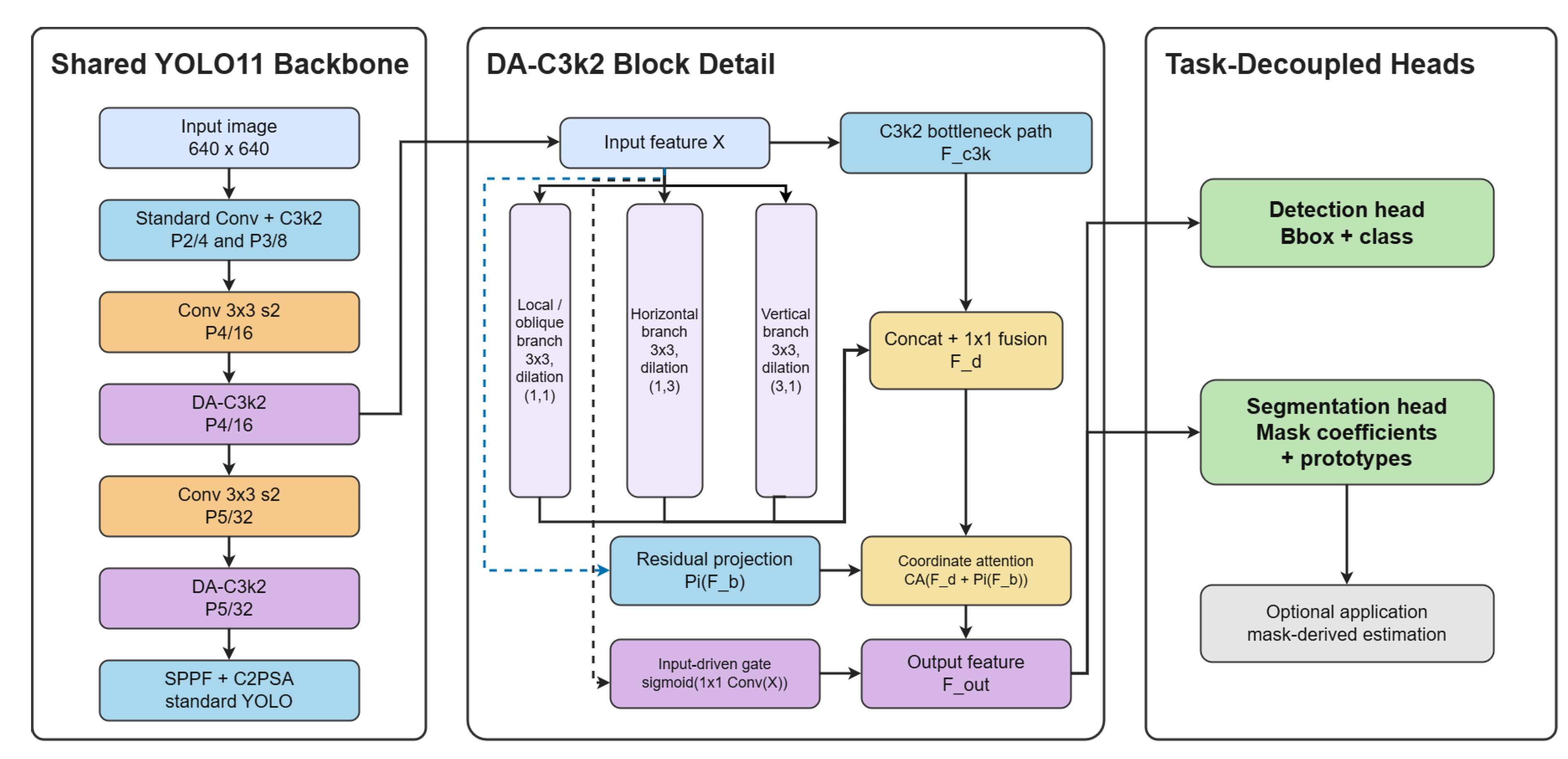
Overall YOLO11-based lightweight crack analysis architecture. Standard YOLO modules include Conv, C3k2, SPPF, C2PSA, feature pyramid operations, and task heads. The C3k2 units at the P4/16 and P5/32 backbone stages are replaced by DA-C3k2 blocks, while the detection and segmentation heads remain task-specific.
Figure 1.
Overall YOLO11-based lightweight crack analysis architecture. Standard YOLO modules include Conv, C3k2, SPPF, C2PSA, feature pyramid operations, and task heads. The C3k2 units at the P4/16 and P5/32 backbone stages are replaced by DA-C3k2 blocks, while the detection and segmentation heads remain task-specific.
3.2. Shared Backbone and Task-Decoupled Supervision
The backbone is based on YOLO11n. In the detection model, the standard C3k2 blocks at layer 6 (P4/16, 512 output channels before width scaling) and layer 8 (P5/32, 1024 output channels before width scaling) are replaced by DA-C3k2. In the segmentation model, the same replacement is applied to the YOLO11-Seg backbone, while the Segment head is retained. The lower P2 and P3 backbone stages keep standard C3k2 modules to preserve lightweight local texture extraction, and the neck/head C3k2 modules remain unchanged to isolate the contribution of backbone feature representation.
The detection head is supervised with the standard YOLO detection losses for box regression, classification, and distribution focal learning. The segmentation head is supervised by the YOLO instance segmentation objective and, in the sparse-mask setting, by Tversky loss. Since detection and segmentation experiments follow different data splits, epoch schedules, batch sizes, and losses, their results are not mixed in a single ablation table for direct causal attribution.
3.3. Direction-Aware C3k2 Block
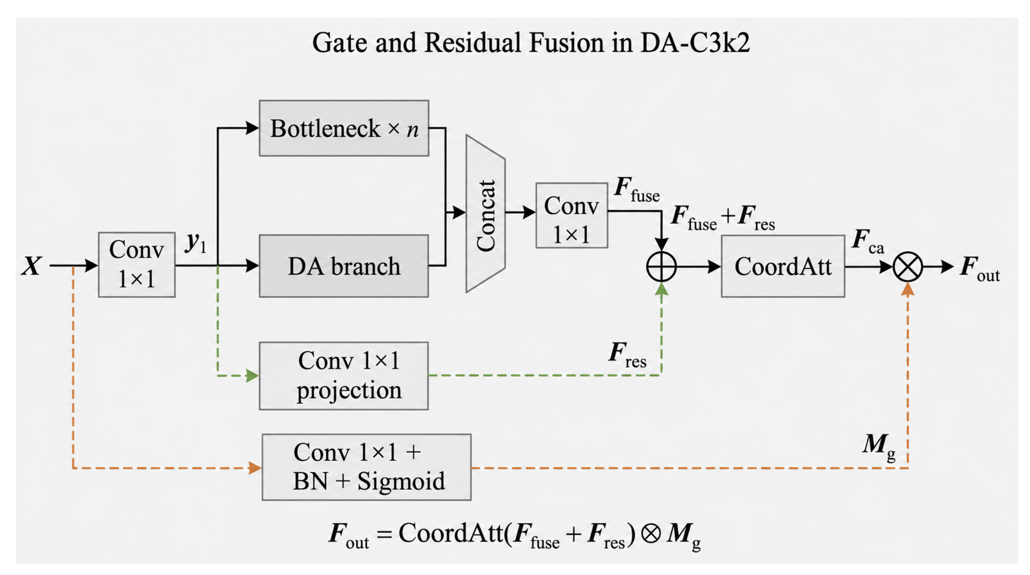
DA-C3k2 keeps the input–output interface of C3k2 and only changes the internal feature transformation. For an input feature map X, a projection first produces a compact baseline feature . This feature is processed by two parallel paths: the original C3k2 bottleneck path and a multi-orientation feature decomposition path. The decomposition path contains three branches:
where is the local and oblique-compatible feature branch, emphasizes horizontally elongated responses, and emphasizes vertically elongated responses. The branch kernel size is for all branches; only the dilation rate differs. Channel counts are aligned to multiples of three so that the three orientation branches can be concatenated without truncation. The decomposed feature is fused with the bottleneck feature by channel concatenation and a convolution:
where denotes the standard C3k2 bottleneck-path feature and denotes pointwise fusion.
Coordinate-guided spatial calibration is applied after orientation decomposition and pointwise fusion, not before it. In the final residual version, the projected baseline feature is added before coordinate attention:
where is a projection used to match the output channel dimension, and denotes coordinate attention with reduction ratio 8. This placement lets coordinate attention recalibrate the already fused direction-aware representation while the residual projection stabilizes the feature distribution.
Finally, gated residual fusion suppresses background line-like responses. The gate is generated from the DA-C3k2 input feature, rather than from the calibrated feature itself:
The gate therefore uses the baseline input feature as a context signal and modulates the calibrated direction-aware output. In implementation, DA-C3k2 is used at the P4/16 and P5/32 backbone stages for both detection and segmentation variants; standard YOLO C2PSA, SPPF, feature pyramid operations, and prediction heads are not renamed as DA-C3k2.
Figure 2.
DA-C3k2 block used in the proposed backbone. The block contains multi-orientation feature decomposition with local/oblique-compatible, horizontal, and vertical branches, coordinate-guided spatial calibration after feature fusion, residual projection, and an input-driven gate applied to the calibrated feature.
Figure 2.
DA-C3k2 block used in the proposed backbone. The block contains multi-orientation feature decomposition with local/oblique-compatible, horizontal, and vertical branches, coordinate-guided spatial calibration after feature fusion, residual projection, and an input-driven gate applied to the calibrated feature.
3.4. Detection Head and Segmentation Head
The detection branch follows the YOLO11n Detect head and predicts crack bounding boxes over three scales, P3/8, P4/16, and P5/32. The head is unchanged relative to YOLO11n, which makes the detection comparison focus on whether DA-C3k2 improves backbone representation for crack localization.
The segmentation branch follows the YOLO11-Seg Segment head. It predicts bounding boxes, class confidence, mask coefficients, and prototype masks. The final instance mask is obtained by combining predicted mask coefficients with learned prototype masks and resizing the result to the image coordinate system. DA-C3k2 affects only shared backbone features; it does not introduce a separate decoder or change the mask inference interface.
3.5. Tversky Loss for Sparse Crack Masks
Crack segmentation is highly imbalanced because crack pixels are sparse relative to the background. To mitigate this issue, Tversky loss is adopted:
where , , and denote true-positive, false-positive, and false-negative pixels, respectively. In the main segmentation protocol, and are used to place a stronger penalty on missed crack pixels. This setting is suitable for thin crack segmentation, where discontinuity and missed branches can strongly affect mask quality.
3.6. Implementation Details
The detection model uses the YOLO11n scale with four crack classes. The segmentation model uses the YOLO11-Seg scale with one crack class. Both models use an input size of . DA-C3k2 is inserted only at the P4/16 and P5/32 backbone positions. The directional branches use kernels with dilation rates , , and , respectively. Coordinate attention is applied after directional fusion and residual projection. The gate uses the block input feature through a convolution, batch normalization, and sigmoid activation, and multiplies the calibrated feature. The exact training protocols are reported in Section 4.2.
3.7. Application Example: Mask-Derived Geometric Estimation
Predicted masks can be used for downstream geometric estimation when a scale coefficient or calibration reference is available. This step is not part of the main contribution or the main experimental conclusion. First, small isolated components can be removed and the main crack region retained. Second, skeletonization can extract the crack centerline. The pixel length is computed from the skeleton path:
where and are adjacent skeleton points and is the Euclidean distance. The physical length is obtained by
where r is the image scale factor that converts pixel measurements into the target physical unit. In this paper, r is treated as an approximate scale coefficient for image-based inspection records rather than full camera calibration or orthorectification. Crack width can be estimated by sampling local normal directions from skeleton points to mask boundaries. The mean width is computed as
where is the local pixel width at the k-th skeleton point. The relative error is computed as
where is the estimate derived from the predicted mask and y is the reference mask-derived value computed from the annotated mask under the same scale coefficient. These values should be interpreted as mask-derived geometric estimation under a scale assumption, not as calibrated physical measurement.
4. Experiments
4.1. Datasets and Evaluation Protocols
Two groups of datasets are used. For detection, the UAV-PDD2023 crack subset is used after removing non-crack categories such as repair and pothole. The remaining four detection classes are alligator, longitudinal, oblique, and transverse cracks. The split contains 1680 training images, 240 validation images, and 480 test images. For segmentation, a crack segmentation benchmark exported in YOLO polygon format is used for the original mask evaluation. An additional COCO-format crack dataset is used only for external transferability and CPU inference evaluation; its validation split contains 200 images and is not used for training.

Table 1.
Dataset and split statistics used in the experiments.
| Experiment | Dataset/source | Classes | Split size | Purpose |
|---|---|---|---|---|
| Detection | UAV-PDD2023 crack subset | 4 crack types | 1680/240/480 | Train/val/test |
| Segmentation | Crack segmentation benchmark | Crack/background | 7704/963/963 | Original mask evaluation |
| External transfer | COCO-format crack export | Crack/background | 1239/200/112 | Validation split for transfer and speed |
Detection is evaluated with mAP50 and mAP50–95. Segmentation ablation on the original benchmark is evaluated with YOLO mask metrics, including mAP50(M), mAP50–95(M), precision, and recall. External transferability is evaluated with Dice, IoU, boundary-F1 (BF1), boundary-IoU (B-IoU), latency, and FPS.
4.2. Training Settings
Table 2 reports the reproducibility-oriented training protocols. The term “final training protocol” denotes a fixed set of training hyperparameters rather than an additional algorithmic component. Detection experiments, segmentation experiments, and Tversky parameter search follow different protocols and are therefore not directly mixed in the same ablation table for causal attribution. The codebase is based on Ultralytics 8.3.241. The training directories archive args.yaml and results.csv; optimizer=auto refers to Ultralytics automatic optimizer selection. The available args.yaml files record optimizer=auto; when console training logs are released, they should be used to report the resolved optimizer, learning rate, and momentum selected by Ultralytics.
4.3. Detection Results
Table 3 compares DA-C3k2 with lightweight YOLO baselines. CPU latency is measured under a unified batch-size-one setting with input size 640, confidence threshold 0.25, and NMS IoU threshold 0.5. DA-C3k2 obtains the best detection accuracy among the compared lightweight models. Compared with the YOLO11n baseline, mAP50 increases from 0.670 to 0.749, and mAP50–95 increases from 0.334 to 0.382. The parameter count increases from 2.59 M to 2.96 M and GFLOPs increase from 6.4 to 6.8, indicating an accuracy–efficiency trade-off rather than a cost-free improvement. CPU latency is reported only as a reproducible efficiency reference; it is not equivalent to real-time UAV edge deployment. The latency differences among YOLO versions may also be affected by framework version, model implementation, and operator optimization.
4.4. Detection Ablation Study
Table 4 reports the detection backbone ablation and separates the effect of the final training protocol from the architectural comparison. The first five rows follow the original ablation protocol and compare structural variants. Direction decomposition alone improves mAP50 from 0.670 to 0.687 and mAP50–95 from 0.334 to 0.353, suggesting that oriented receptive fields are useful for crack localization. Partial combinations do not monotonically improve all metrics, which indicates that spatial calibration, gating, residual fusion, and optimization settings interact with each other. The complete three-stage DA-C3k2 variant obtains the best result under the ablation protocol, improving the baseline from 0.670 to 0.711 mAP50 and from 0.334 to 0.360 mAP50–95. The last two rows use the same final training protocol described in Table 2. Under this fixed protocol, the C3k2 baseline reaches 0.733 mAP50, while DA-C3k2 reaches 0.749 mAP50. Therefore, the final performance should be interpreted as the combined result of a reproducible training protocol and the DA-C3k2 structure, with an additional architectural gain under the final protocol.
Figure 3 visualizes the feature activation maps of the backbone ablation variants using EigenCAM at backbone layer 6. Compared with the baseline C3k2, orientation decomposition shifts the activation from diffuse background texture toward elongated crack-like structures. Adding coordinate calibration further concentrates responses around crack regions, while the three-stage DA-C3k2 variant produces more continuous activation along long crack trajectories. The orientation-gated variant suppresses part of the background response, although some non-crack line structures may still be activated. These qualitative results are consistent with the quantitative ablation trend: direction-aware components help the backbone focus on crack-relevant elongated patterns, while partial module combinations do not always yield monotonic metric gains.
Table 5 further reports the per-class AP changes between the YOLO11n baseline and the final DA-C3k2 detector. The largest gain is obtained for alligator cracks, followed by oblique and transverse cracks, suggesting that the proposed direction-aware feature modeling is particularly useful for irregular or direction-sensitive crack patterns.
The class-wise results show that DA-C3k2 does not improve all categories uniformly. The most pronounced improvement occurs for alligator cracks, whose AP increases by 9.4 percentage points. Oblique and transverse cracks also obtain clear gains of 4.7 and 4.3 percentage points, respectively. These categories usually contain irregular, crossing, or direction-changing visual structures, and therefore benefit more from the anisotropic directional branches. The gain for longitudinal cracks is smaller because the baseline already performs strongly on this visually more regular class.
Figure 4 provides a complementary view of the final detector. Most true crack instances are concentrated on the diagonal, indicating that the model can distinguish the four crack categories under the validation protocol. The remaining errors mainly come from missed detections assigned to the background column and from confusion between visually similar elongated crack types. This is consistent with the per-class AP analysis: direction-aware modeling improves irregular and oblique crack recognition, but fine-grained separation between elongated crack categories remains challenging in UAV bridge images.
4.5. Segmentation Ablation Results
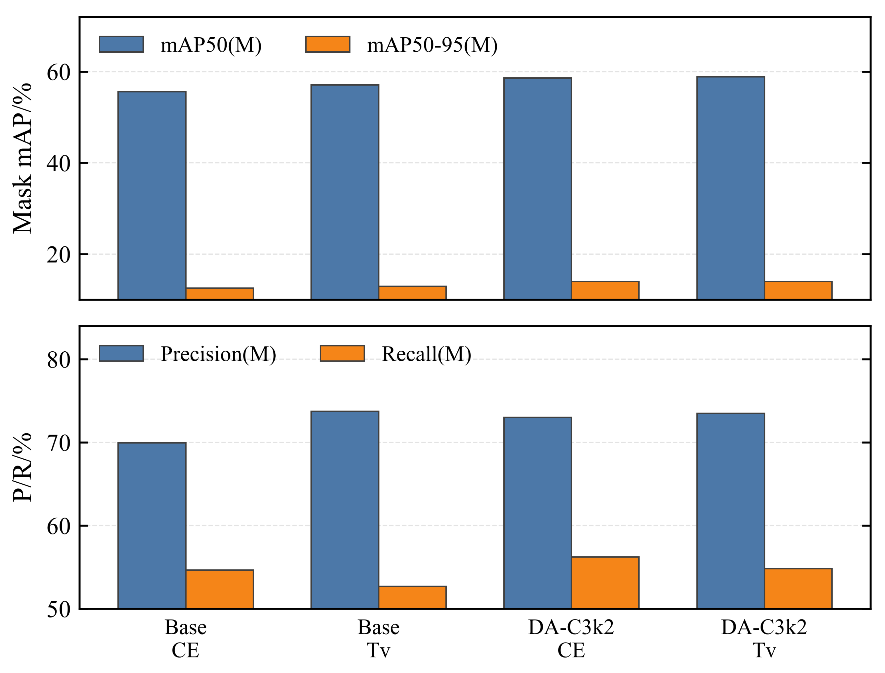
Table 6 presents segmentation ablation results on the original benchmark. These values are YOLO mask metrics, not Dice/IoU/BF1/B-IoU. DA-C3k2 under CE loss improves mask mAP over the CE baseline, showing that the direction-aware structure helps crack mask representation. Tversky loss improves the baseline mAP50(M) over CE, indicating that foreground-sensitive supervision is useful for sparse crack masks. DA-C3k2 with Tversky loss obtains the highest mAP50(M) and mAP50–95(M), but its Recall(M) is lower than DA-C3k2 with CE. Therefore, the result should be interpreted as the best overall mask mAP with a precision–recall trade-off, not as a uniform improvement over all metrics.
Figure 5.
Segmentation ablation results under CE and Tversky loss settings.
4.6. Segmentation Comparison with Larger Semantic Segmentation Models
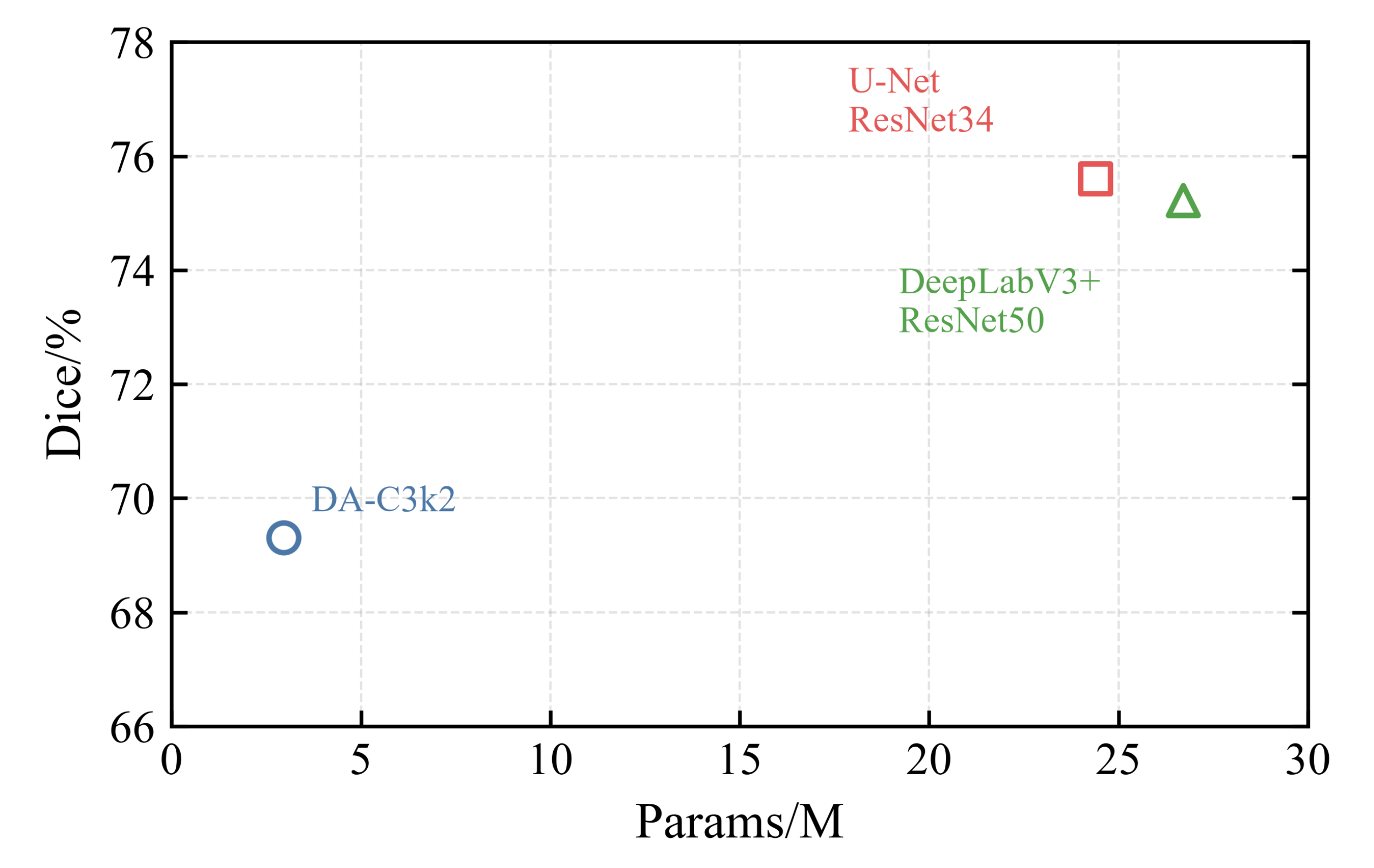
Table 7 compares the lightweight YOLO11-Seg variant with larger semantic segmentation models. U-Net with ResNet34 and DeepLabV3+ with ResNet50 achieve higher Dice and IoU, but they require substantially more parameters. The DA-C3k2-based lightweight model provides a compact alternative when detection and instance-mask prediction are considered together.
Figure 6.
Parameter–Dice comparison between the proposed lightweight model and larger segmentation baselines.
Figure 6.
Parameter–Dice comparison between the proposed lightweight model and larger segmentation baselines.
4.7. External Dataset Transferability Evaluation
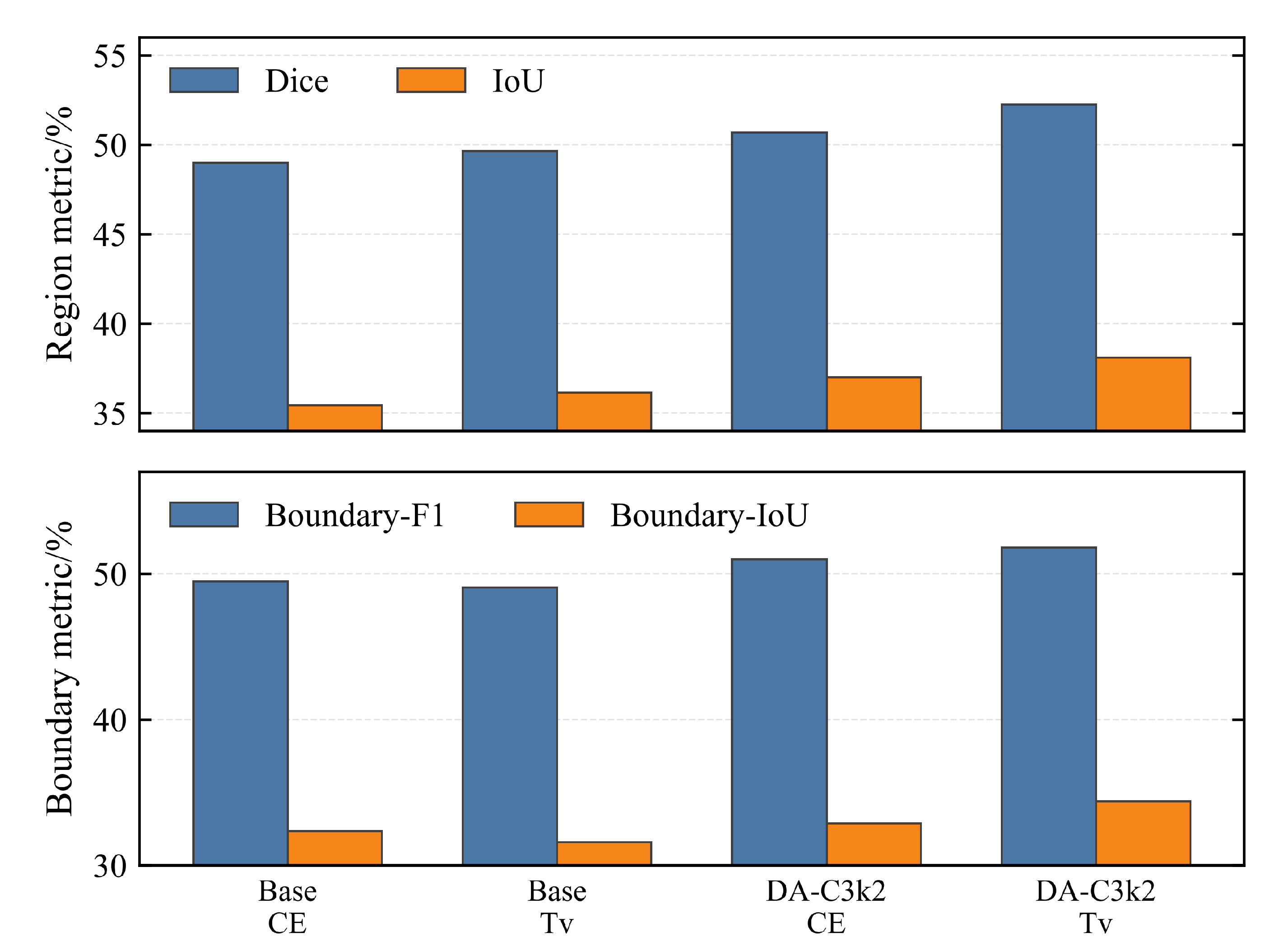
Table 8 reports external evaluation on the COCO-format crack dataset. The four rows follow the same configuration order as the segmentation ablation table. DA-C3k2 with Tversky loss obtains the highest Dice, IoU, BF1, and B-IoU, suggesting that the direction-aware shared backbone and foreground-sensitive loss provide generalization benefits for cross-domain crack mask prediction. Its CPU speed is 7.20 FPS, which remains acceptable as a reproducible CPU reference under the reported evaluation setting.
Figure 7.
External COCO-format crack dataset evaluation for transferability analysis.
4.8. CPU Inference Efficiency
Table 8 includes CPU latency and FPS for the four main transferability configurations. All models are evaluated with batch size 1, input size 640, confidence threshold 0.25, NMS IoU threshold 0.5, and 200 validation images. These CPU results provide a reproducible efficiency reference for lightweight inspection settings, while deployment-oriented GPU or edge-device profiling remains hardware-dependent.
4.9. Qualitative Analysis
The qualitative results include detection boxes, segmentation masks, extracted crack skeletons, width sampling lines, and failure cases. Detection visualizations verify whether crack regions are correctly localized. Segmentation masks show whether thin branches and crack boundaries are preserved. Skeleton and width sampling visualizations are used only to illustrate the downstream use of predicted masks under a scale assumption. Failure cases mainly include missed low-contrast cracks, false positives caused by bridge surface seams or stains, fragmented masks in shadowed regions, and unstable boundary sampling when the predicted mask is noisy.
5. Discussion
The experimental results show that DA-C3k2 improves crack localization with a small increase in model complexity. This is consistent with the geometry of bridge cracks. Thin cracks are often directionally continuous but locally weak in texture, so square local sampling alone may not provide enough long-axis context. DA-C3k2 expands the receptive field along horizontal and vertical directions, keeps a local branch for oblique-compatible responses, recalibrates the fused feature with coordinate attention, and uses an input-driven gate to suppress redundant background activations. The ablation results also show that partial feature operations do not always produce monotonic gains, which suggests that the benefit comes from the complete direction-aware block and its stable integration into the backbone.
For segmentation, Tversky loss is useful because crack masks are sparse. A small number of missed foreground pixels can break a thin crack into disconnected fragments. By assigning a larger penalty to false negatives, Tversky supervision encourages foreground preservation. The segmentation ablation also shows a precision–recall trade-off: DA-C3k2 with Tversky loss obtains the best mask mAP, while DA-C3k2 with CE gives higher recall. This is why the paper reports the trade-off explicitly rather than claiming uniform improvement across all metrics.
The external transfer results reveal clear domain shift. DA-C3k2 with Tversky loss obtains the highest Dice, IoU, BF1, and B-IoU on the external COCO-format crack dataset, but the absolute metric values remain lower than those expected under an in-domain setting. Differences in image source, crack texture, annotation style, background material, and image resolution may all contribute to this decrease. Therefore, external validation is necessary before lightweight crack segmentation models are used in practical bridge inspection workflows.
This paper does not claim strict end-to-end validation of detection, segmentation, and geometric estimation on a single calibrated data chain. The contribution is limited to direction-aware feature modeling and sparse-foreground optimization for the detection and segmentation stages. Mask-derived geometric estimation is included only as a downstream application example. Such estimation depends on scale coefficients, mask quality, boundary accuracy, skeleton continuity, and calibration availability. Without calibrated camera intrinsics, UAV pose compensation, orthorectified imaging, or fiducial markers, the estimated length and width should be treated as approximate inspection assistance.
The method still has limitations. First, the directional branches mainly model local, horizontal, and vertical responses, so highly curved cracks or complex branching patterns may require richer orientation modeling. Second, the lightweight segmentation model remains below larger semantic segmentation networks in Dice and IoU, indicating a capacity–accuracy trade-off. Third, CPU latency is only a reproducible efficiency reference and should not be interpreted as a deployment guarantee for UAV onboard hardware. Future work will focus on calibrated image acquisition, uncertainty-aware mask evaluation, boundary-sensitive losses, and edge-device profiling.
6. Conclusions
This paper proposed a lightweight DA-C3k2 network for UAV-based bridge crack detection and segmentation. DA-C3k2 replaces selected P4/16 and P5/32 backbone C3k2 blocks with multi-orientation feature decomposition, coordinate-guided spatial calibration, and gated residual fusion. The shared backbone provides direction-aware crack features, while detection and segmentation heads are supervised with task-specific objectives.
On the UAV-PDD2023 crack subset, the final DA-C3k2 detector improved mAP50 from 0.670 to 0.749 and mAP50–95 from 0.334 to 0.382 compared with the YOLO11n baseline, while using 2.96 M parameters and 6.8 GFLOPs. Under the same final training protocol, DA-C3k2 further improved the C3k2 baseline from 0.733 to 0.749 mAP50 and from 0.373 to 0.382 mAP50–95. In segmentation, DA-C3k2 with Tversky loss achieved the best mask mAP among the evaluated lightweight variants, and on the external COCO-format crack dataset it obtained 0.5225 Dice, 0.3811 IoU, 0.5182 BF1, and 0.3439 B-IoU with 7.20 FPS CPU inference.
These results indicate that DA-C3k2 and Tversky loss are effective for lightweight crack localization and mask prediction. The predicted masks can support downstream geometric estimation under appropriate scale assumptions, but calibrated geometric measurement remains a separate requirement for future work.
Author Contributions
Conceptualization, K.L. and H.W.; methodology, K.L.; software, K.L.; validation, K.L., K.W. and L.J.; formal analysis, K.L.; investigation, K.L.; resources, H.W.; data curation, K.L.; writing—original draft preparation, K.L.; writing—review and editing, H.W., K.W. and L.J.; visualization, K.L.; supervision, H.W.; project administration, H.W.; funding acquisition, H.W. All authors have read and agreed to the published version of the manuscript.
Funding
This research was funded by the Shaanxi Provincial Key Research and Development Program, grant number 2025CY-JJQ-25.
Institutional Review Board Statement
Not applicable.
Informed Consent Statement
Not applicable.
Data Availability Statement
The public datasets used in this study include UAV-PDD2023, CFD, CRACK500, and an external COCO-format crack dataset for transferability evaluation. Processed annotations, trained weights, and code are available from the corresponding author upon reasonable request, subject to dataset license restrictions.
Acknowledgments
The authors thank the members of the research group for their assistance with dataset organization and experimental verification.
Conflicts of Interest
The authors declare no conflicts of interest. The funders had no role in the design of the study; in the collection, analyses, or interpretation of data; in the writing of the manuscript; or in the decision to publish the results.
Abbreviations
The following abbreviations are used in this manuscript:
| BF1 | Boundary-F1 score |
| B-IoU | Boundary intersection over union |
| CA | Coordinate attention |
| CE | Cross-entropy |
| DA-C3k2 | Direction-Aware C3k2 block |
| GFLOPs | Giga floating-point operations |
| mAP | Mean average precision |
| UAV | Unmanned aerial vehicle |
References
- Deng, J.; Singh, A.; Zhou, Y.; Lu, Y.; Lee, V.C.S. Review on computer vision-based crack detection and quantification methodologies for civil structures. Constr. Build. Mater. 2022, 356, 129238. [Google Scholar] [CrossRef]
- Ai, D.; Jiang, G.; Lam, S.K.; He, P.; Li, C. Computer vision framework for crack detection of civil infrastructure-A review. Eng. Appl. Artif. Intell. 2023, 117, 105478. [Google Scholar] [CrossRef]
- Luo, K.; Kong, X.; Zhang, J.; Hu, J.; Li, J.; Tang, H. Computer Vision-Based Bridge Inspection and Monitoring: A Review. Sensors 2023, 23, 7863. [Google Scholar] [CrossRef] [PubMed]
- Aliyari, M.; Droguett, E.L.; Ayele, Y.Z. UAV-Based Bridge Inspection via Transfer Learning. Sustainability 2021, 13, 11359. [Google Scholar] [CrossRef]
- Saeed, M.S. Unmanned Aerial Vehicle for Automatic Detection of Concrete Crack using Deep Learning. In Proceedings of the 2021 2nd International Conference on Robotics, Electrical and Signal Processing Techniques (ICREST), 2021; pp. 624–628. [Google Scholar] [CrossRef]
- Phan, T.N.; Nguyen, H.H.; Ha, T.T.H.; Thai, H.T.; Le, K.H. Deep Learning Models for UAV-Assisted Bridge Inspection: A YOLO Benchmark Analysis. In Proceedings of the 2024 International Conference on Advanced Technologies for Communications (ATC), 2024. [Google Scholar] [CrossRef]
- Cha, Y.J.; Choi, W.; Buyukozturk, O. Deep Learning-Based Crack Damage Detection Using Convolutional Neural Networks. In Computer-Aided Civil and Infrastructure Engineering; 2017. [Google Scholar] [CrossRef]
- Zhang, L.; Yang, F.; Zhang, Y.D.; Zhu, Y.J. Road crack detection using deep convolutional neural network. In Proceedings of the 2016 IEEE International Conference on Image Processing (ICIP), 2016. [Google Scholar] [CrossRef]
- Xu, H.; Su, X.; Wang, Y.; Cai, H.; Cui, K.; Chen, X. Automatic Bridge Crack Detection Using a Convolutional Neural Network. Appl. Sci. 2019, 9, 2867. [Google Scholar] [CrossRef]
- Liu, Y.; Zhou, T.; Xu, J.; Hong, Y.; Pu, Q.; Wen, X. Rotating Target Detection Method of Concrete Bridge Crack Based on YOLO v5. Appl. Sci. 2023, 13, 11118. [Google Scholar] [CrossRef]
- Zou, X.; Jiang, S.; Yang, J.; Huang, X. Concrete Bridge Crack Detection Based on YOLO v8s in Complex Background. In Proceedings of International Conference on Image, Vision and Intelligent Systems 2023 (ICIVIS 2023); Springer Nature Singapore, 2024; pp. 436–443. [Google Scholar] [CrossRef]
- Yu, A.; Gao, Y.; Xiong, Y.; Liu, W.; She, J. Mobile-YOLO: A Lightweight YOLO for Road Crack Detection on Mobile Devices. J. Adv. Comput. Intell. Intell. Inform. 2025, 29, 1443–1453. [Google Scholar] [CrossRef]
- Ronneberger, O.; Fischer, P.; Brox, T. U-Net: Convolutional Networks for Biomedical Image Segmentation. In Medical Image Computing and Computer-Assisted Intervention – MICCAI 2015; Springer International Publishing, 2015; pp. 234–241. [Google Scholar] [CrossRef]
- Zou, Q.; Zhang, Z.; Li, Q.; Qi, X.; Wang, Q.; Wang, S. DeepCrack: Learning Hierarchical Convolutional Features for Crack Detection. IEEE Trans. Image Process. 2019, 28, 1498–1512. [Google Scholar] [CrossRef] [PubMed]
- Liu, Y.; Yao, J.; Lu, X.; Xie, R.; Li, L. DeepCrack: A deep hierarchical feature learning architecture for crack segmentation. Neurocomputing 2019, 338, 139–153. [Google Scholar] [CrossRef]
- Sun, X.; Xie, Y.; Jiang, L.; Cao, Y.; Liu, B. DMA-Net: DeepLab With Multi-Scale Attention for Pavement Crack Segmentation. IEEE Trans. Intell. Transp. Syst. 2022, 23, 18392–18403. [Google Scholar] [CrossRef]
- Abraham, N.; Khan, N.M. A Novel Focal Tversky Loss Function With Improved Attention U-Net for Lesion Segmentation. In Proceedings of the 2019 IEEE 16th International Symposium on Biomedical Imaging (ISBI 2019); IEEE, Apr 2019; pp. 683–687. [Google Scholar] [CrossRef]
- Wang, M.; Liu, Y.; Hao, Y.; Gong, S.; Qiu, C.; Cai, R.; Deng, Y. Research on road crack detection algorithm based on YOLO-SW. PeerJ Comput. Sci. 2026, 12, e3783. [Google Scholar] [CrossRef]
- Chen, L.C.; Zhu, Y.; Papandreou, G.; Schroff, F.; Adam, H. Encoder-Decoder with Atrous Separable Convolution for Semantic Image Segmentation. In Computer Vision – ECCV 2018; Springer International Publishing, 2018; pp. 833–851. [Google Scholar] [CrossRef]
- Yang, L.; Bai, S.; Liu, Y.; Yu, H. Multi-scale triple-attention network for pixelwise crack segmentation. Autom. Constr. 2023, 150, 104853. [Google Scholar] [CrossRef]
- Yue, B.; Dang, J.; Sun, Q.; Wang, Y.; Min, Y.; Wang, F. TSPCS-net: Two-stage pavement crack segmentation network based on encoder-decoder architecture. Eng. Appl. Artif. Intell. 2025, 141, 109840. [Google Scholar] [CrossRef]
- Lin, T.Y.; Goyal, P.; Girshick, R.; He, K.; Dollar, P. Focal Loss for Dense Object Detection. In Proceedings of the 2017 IEEE International Conference on Computer Vision (ICCV); IEEE, Oct 2017; pp. 2999–3007. [Google Scholar] [CrossRef]
- Milletari, F.; Navab, N.; Ahmadi, S.A. V-Net: Fully Convolutional Neural Networks for Volumetric Medical Image Segmentation. In Proceedings of the 2016 Fourth International Conference on 3D Vision (3DV); IEEE, Oct 2016; pp. 565–571. [Google Scholar] [CrossRef]
- Cho, H.; Yoon, H.J.; Jung, J.Y. Image-Based Crack Detection Using Crack Width Transform (CWT) Algorithm. IEEE Access 2018, 6, 60100–60114. [Google Scholar] [CrossRef]
- Yu, L.; He, S.; Liu, X.; Jiang, S.; Xiang, S. Intelligent Crack Detection and Quantification in the Concrete Bridge: A Deep Learning-Assisted Image Processing Approach. Adv. Civ. Eng. 2022. [Google Scholar] [CrossRef]
- Li, C.; Qin, H.; Tang, Y.; Zhao, H.; Pan, S.; Liu, J.; Luo, W. An Image-Based Concrete-Crack-Width Measurement Method Using Skeleton Pruning and the Edge-OrthoBoundary Algorithm. Buildings 2025, 15, 2489. [Google Scholar] [CrossRef]
Figure 3.
EigenCAM feature activation visualization for detection backbone ablation at backbone layer 6. From left to right, each row shows the original image with ground-truth boxes, Baseline C3k2, Orientation decomposition, Orientation + calibration, Three-stage DA-C3k2, and Orientation + gate.
Figure 3.
EigenCAM feature activation visualization for detection backbone ablation at backbone layer 6. From left to right, each row shows the original image with ground-truth boxes, Baseline C3k2, Orientation decomposition, Orientation + calibration, Three-stage DA-C3k2, and Orientation + gate.
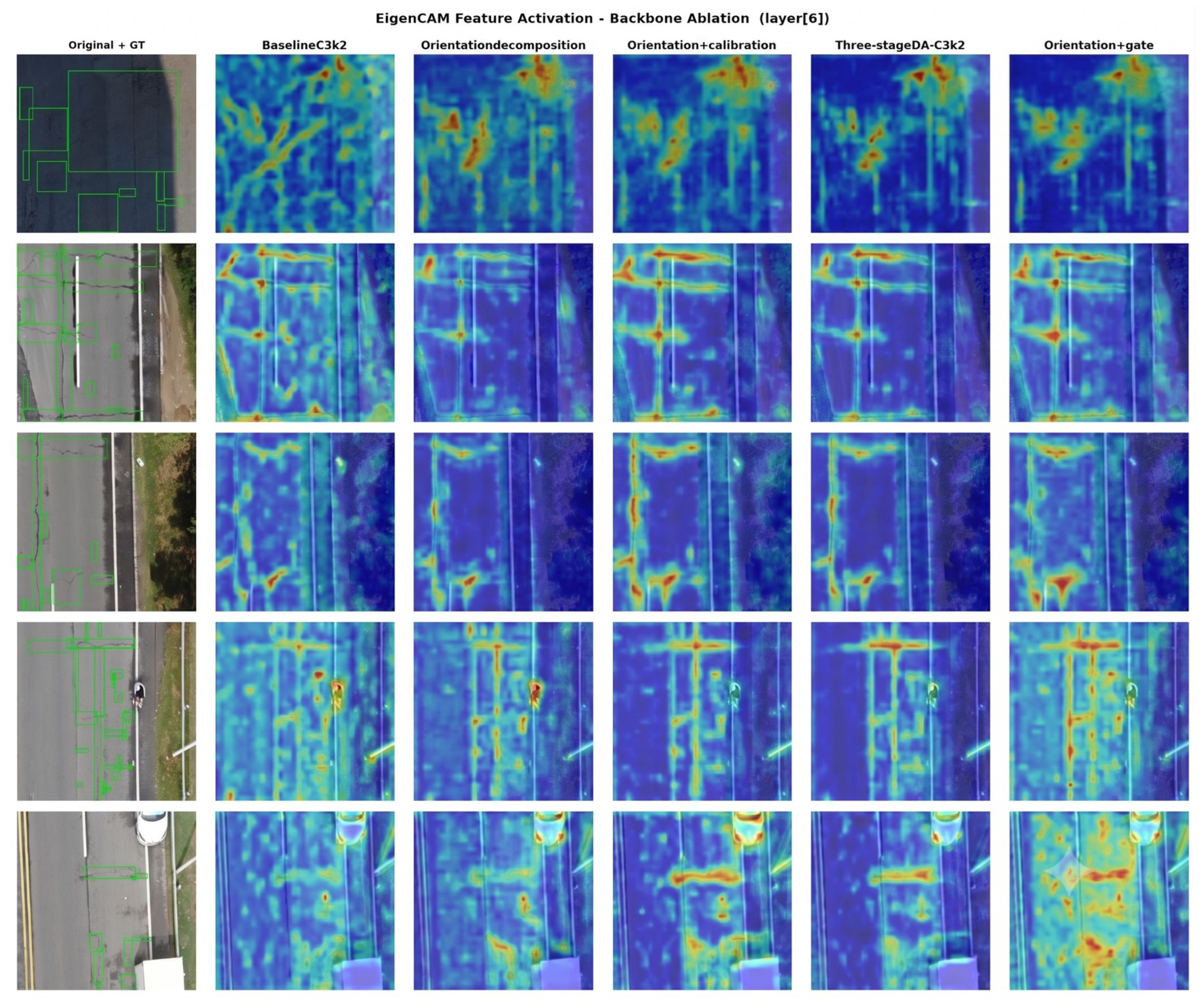
Figure 4.
Normalized confusion matrix of the final DA-C3k2 detector on the UAV-PDD2023 crack validation subset.
Figure 4.
Normalized confusion matrix of the final DA-C3k2 detector on the UAV-PDD2023 crack validation subset.
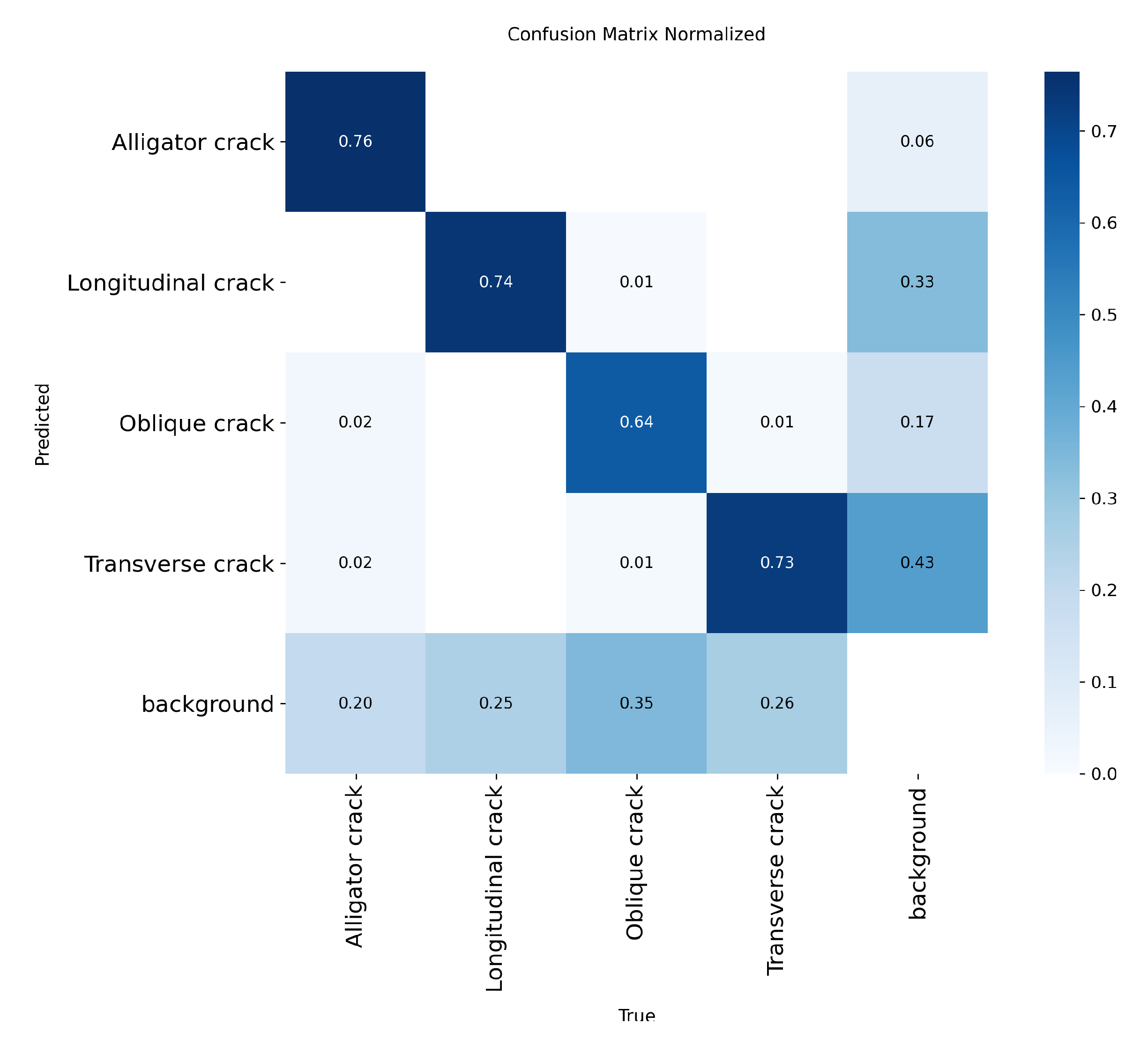
Table 2.
Training protocols for detection, segmentation, and Tversky parameter search.
| Protocol | Item | Setting |
|---|---|---|
| Detection | Model and schedule | YOLO11n with DA-C3k2; input size 640×640; 300 epochs; batch size 256; seed 0. |
| Detection | Optimization and loss | optimizer=auto; lr0=0.01; lrf=0.001; momentum 0.937; weight decay 0.0005; loss gains: box=7.5, cls=1.0, dfl=1.5. |
| Detection | Augmentation | mosaic=1.0; close_mosaic=50; HSV h/s/v=0.015/0.7/0.4; translate=0.1; scale=0.5; degrees=0; shear=0; fliplr=0.5; flipud=0; mixup/cutmix=0/0. |
| Detection | Validation | warmup epochs=3.0; validation NMS IoU=0.7; AMP enabled. |
| Segmentation | Model and schedule | YOLO11-Seg with DA-C3k2; input size 640×640; 80 fine-tuning epochs; batch size 64; seed 42. |
| Segmentation | Optimization and loss | optimizer=auto; lr0=0.001; lrf=0.1; momentum 0.937; weight decay 0.0005; loss gains: box=7.5, cls=0.5, dfl=1.5; Tversky weight , , . |
| Segmentation | Augmentation | mosaic=1.0; close_mosaic=10; HSV h/s/v=0.015/0.7/0.4; translate=0.1; scale=0.5; degrees=10; shear=2; fliplr=0.5; flipud=0.5; mixup/cutmix=0/0. |
| Segmentation | Validation and application thresholds | warmup epochs=1.0; validation NMS IoU=0.7; application-example thresholds: confidence=0.25, NMS IoU=0.5, mask threshold=0.5; AMP enabled. |
| Tversky search | Model and schedule | YOLO11-Seg; input size 640×640; 80 epochs; batch size 256; seed 42. |
| Tversky search | Optimization and loss | optimizer=auto; lr0=0.001; lrf=0.1; Tversky weight . |
| Tversky search | Search space and augmentation | , searched from 0.1/0.9 to 0.5/0.5; the remaining augmentation settings follow the segmentation protocol; AMP enabled. |
Table 3.
Detection comparison with lightweight YOLO baselines.
| Method | Params/M | GFLOPs | Latency/ms | FPS | mAP50 | mAP50–95 |
|---|---|---|---|---|---|---|
| YOLOv8n | 3.20 | 8.7 | 109.54 | 9.13 | 0.626 | 0.316 |
| YOLOv10n | 2.30 | 6.7 | 114.03 | 8.77 | 0.487 | 0.216 |
| YOLO11n baseline | 2.59 | 6.4 | 213.71 | 4.68 | 0.670 | 0.334 |
| YOLO12n | 2.60 | 6.3 | 234.40 | 4.27 | 0.371 | 0.147 |
| DA-C3k2 | 2.96 | 6.8 | 220.64 | 4.53 | 0.749 | 0.382 |
Table 4.
Detection ablation study and final training protocol check on the UAV-PDD2023 crack subset.
Table 4.
Detection ablation study and final training protocol check on the UAV-PDD2023 crack subset.
| Configuration | Params/M | GFLOPs | mAP50 | mAP50–95 |
|---|---|---|---|---|
| Baseline C3k2 | 2.59 | 6.4 | 0.670 | 0.334 |
| Orientation decomposition | 2.86 | 6.7 | 0.687 | 0.353 |
| Orientation + calibration | 2.89 | 6.8 | 0.683 | 0.347 |
| Orientation + gated fusion | 2.94 | 6.8 | 0.693 | 0.351 |
| Three-stage DA-C3k2 | 2.97 | 6.9 | 0.711 | 0.360 |
| Baseline C3k2 + final protocol | 2.59 | 6.4 | 0.733 | 0.373 |
| DA-C3k2 + final protocol | 2.96 | 6.8 | 0.749 | 0.382 |
Table 5.
Per-class AP improvement of the final DA-C3k2 detector over the YOLO11n baseline.
| Class | Baseline AP | DA-C3k2 AP | Absolute gain | Relative gain |
|---|---|---|---|---|
| Alligator crack | 0.729 | 0.823 | +0.094 | +12.9% |
| Longitudinal crack | 0.741 | 0.754 | +0.013 | +1.8% |
| Oblique crack | 0.591 | 0.638 | +0.047 | +8.0% |
| Transverse crack | 0.712 | 0.755 | +0.043 | +6.0% |
Table 6.
Segmentation ablation of DA-C3k2 and Tversky loss on the original benchmark.
| Configuration | Loss | mAP50(M) | mAP50–95(M) | Prec(M) | Recall(M) |
|---|---|---|---|---|---|
| Baseline | CE | 0.5562 | 0.1257 | 0.6997 | 0.5467 |
| Baseline | Tversky | 0.5707 | 0.1295 | 0.7377 | 0.5269 |
| Baseline+DA-C3k2 | CE | 0.5861 | 0.1400 | 0.7301 | 0.5623 |
| Baseline+DA-C3k2 | Tversky | 0.5889 | 0.1406 | 0.7352 | 0.5483 |
Table 7.
Segmentation comparison with larger semantic segmentation models.
| Method | Params/M | Dice | IoU |
|---|---|---|---|
| DA-C3k2 lightweight model | 2.96 | 0.6931 | 0.5603 |
| U-Net ResNet34 | 24.40 | 0.7560 | 0.6079 |
| DeepLabV3+ ResNet50 | 26.70 | 0.7522 | 0.6030 |
Table 8.
External transferability evaluation on the COCO-format crack dataset.
| Configuration | Dice | IoU | BF1 | B-IoU | Latency/ms | FPS |
|---|---|---|---|---|---|---|
| Baseline+CE | 0.4899 | 0.3543 | 0.4950 | 0.3234 | 154.97 | 6.45 |
| Baseline+Tversky | 0.4966 | 0.3615 | 0.4907 | 0.3160 | 201.49 | 4.96 |
| Baseline+DA-C3k2+CE | 0.5068 | 0.3701 | 0.5100 | 0.3288 | 133.58 | 7.49 |
| Baseline+DA-C3k2+Tversky | 0.5225 | 0.3811 | 0.5182 | 0.3439 | 138.94 | 7.20 |
Disclaimer/Publisher’s Note: The statements, opinions and data contained in all publications are solely those of the individual author(s) and contributor(s) and not of MDPI and/or the editor(s). MDPI and/or the editor(s) disclaim responsibility for any injury to people or property resulting from any ideas, methods, instructions or products referred to in the content. |
© 2026 by the authors. Licensee MDPI, Basel, Switzerland. This article is an open access article distributed under the terms and conditions of the Creative Commons Attribution (CC BY) license (http://creativecommons.org/licenses/by/4.0/).
Copyright: This open access article is published under a Creative Commons CC BY 4.0 license, which permit the free download, distribution, and reuse, provided that the author and preprint are cited in any reuse.


