

Submitted:
15 July 2026
Posted:
16 July 2026
You are already at the latest version
Abstract
Electric-vehicle (EV) gearboxes operate under low acoustic masking and high rotational speeds, making tonal noise and unit-to-unit NVH scatter especially relevant. However, many gearbox noise, vibration, and harshness (NVH) simulations still rely on nominal geometry, ideal assembly conditions, and simplified supports. Such models are useful for early design, but they are often insufficient for explaining the behavior of manufactured and assembled EV drive units. This structured narrative review develops a simula-tion-ready parameter framework that links manufacturing measurements, assembly data, operating conditions, and degradation indicators to numerical representations used in loaded tooth contact analysis, multibody dynamics, finite element structural models, and vibroacoustic simulation. Unlike component-centered reviews, the proposed framework classifies parameters simultaneously by physical origin and by their role in the excita-tion-transfer-radiation chain. It also introduces four simulation-readiness lev-els—nominal, tolerance-based, measurement-based, and variability-aware—and priori-tizes inputs as baseline, recommended, or advanced. Particular attention is given to gear microgeometry and flank deviations, pitch error, runout, flank waviness, bearing preload and stiffness, assembly misalignment, housing variability, motor-side excitation, temper-ature, lubrication, and wear. An illustrative EV gearbox implementation scenario demon-strates how the framework can be used to progress from concept-level prediction to pro-duction-scatter analysis. The resulting structure provides a common data-request and model-building guideline for EV powertrain development, validation, root-cause analysis, and data-driven NVH modeling.
Keywords:
electric vehicle gearbox
; powertrain NVH
; transmission error
; manufacturing variability
; assembly misalignment
; bearing stiffness
; gear microgeometry
; flank waviness
; vibroacoustic simulation
; simulation-ready parameters
1. Introduction
The acoustic environment of electric vehicles places unusually strong demands on gearbox design. The absence of dominant combustion noise reduces masking, while high motor speeds shift gear-mesh harmonics and sidebands into frequency ranges that can be perceptually prominent. Consequently, small differences in tooth geometry, bearing support, assembly alignment, housing dynamics, and operating temperature may become audible and may cause nominally identical electric drive units to exhibit different NVH behavior [1,2,3,4,5].
The physical mechanisms behind gearbox NVH are well known in principle. Gear meshing generates dynamic excitation. Transmission error (TE) and time-varying mesh stiffness are central to this process. The resulting forces pass through shafts and bearings into the housing. The housing then responds according to its modal behavior, local stiffness, damping, and boundary conditions. Finally, part of this vibration is radiated as airborne sound. This excitation-transfer-radiation view appears already in classical gearbox acoustics literature and remains relevant in modern system-level simulation studies [1,6,7,8,9,10,11].
Despite this established physical background, the literature remains fragmented from the viewpoint of EV powertrain development. Existing studies commonly examine one part of the chain—such as transmission error, microgeometry, bearing stiffness, housing response, electromagnetic excitation, or acoustic radiation—without defining a common set of physical data that can be transferred from manufacturing and testing into coupled simulation models. The unresolved practical question is therefore not only how to model gearbox NVH, but which measured parameters are required to make the model representative of an as-built electric drive unit.
This gap is particularly important for electric-vehicle gearboxes. A nominal computer-aided design (CAD) model describes the intended design, but not necessarily the unit that is manufactured, assembled, thermally stabilized, tested, and aged. Real systems contain profile and lead deviations, pitch error, runout, shaft and bearing-seat offsets, backlash variation, bearing preload and clearance scatter, wall-thickness variation, lubricant-state changes, and motor-side torque ripple. These parameters can alter the excitation, transfer, structural-response, and radiation stages individually or simultaneously [10,11,12,13,14,15].
Bearings provide a clear example. They are sometimes treated as simple supports, but they are part of the dynamic transfer path. They guide the shafts, influence mesh alignment, and transmit dynamic forces into the housing. Mayeux et al. coupled meshing stiffness and bearing stiffness and showed that this interaction affects the radiated gearbox noise [10]. Zhang et al. also demonstrated the relevance of identifying dynamic forces transmitted through bearings into the housing [11]. These studies support the view that a gear-only model is not sufficient for system-level NVH prediction.
Manufacturing variability adds another layer. Driot et al. investigated the variability of gearbox critical rotational speeds caused by misalignment and manufacturing errors, including profile and longitudinal tooth errors [13]. Their work is important because it treats deviations as variability sources, not only as isolated deterministic defects. This is close to the practical problem addressed in the present review.
The objective of this paper is to develop a simulation-ready parameter framework for EV gearbox NVH modeling under manufacturing, assembly, operating, and degradation variability. The framework is not intended to replace detailed gear, bearing, structural, or acoustic standards. Its novelty lies in connecting four elements that are usually treated separately: the physical origin of variability, its function in the excitation-transfer-radiation chain, the numerical representation required by each simulation domain, and the level of evidence that supports the resulting model. This provides a structured route from nominal design data to measurement-based and population-level EV gearbox models.
The main contributions are as follows:
- An EV-oriented classification of NVH-relevant manufacturing, assembly, bearing, shaft, housing, operating, and degradation parameters is proposed.
- A dual classification separates physical origin from NVH function, thereby connecting production data with excitation, transfer-path, structural-response, and radiation mechanisms.
- Four simulation-readiness levels distinguish nominal, tolerance-based, measurement-based, and variability-aware models and clarify the claims each model can support.
- A physical-parameter-to-numerical-representation mapping is established for LTCA, MBD, FEM, vibroacoustic, and hybrid data-driven workflows.
- A tiered data-request guideline and an illustrative EV gearbox application scenario are introduced to support industrial implementation.
The remainder of the paper is organized as follows. Section 2 describes the literature-search strategy, source-selection logic, parameter-extraction process, and framework-development method used in this structured narrative review. Section 3 establishes the conceptual basis of the proposed framework. It explains the excitation-transfer-radiation chain, the two parameter-classification levels, the simulation-readiness levels, and the physical-to-numerical mapping principle. Section 4 discusses manufacturing-related gear parameters, including nominal macrogeometry, microgeometry, profile and lead deviations, pitch error, runout, and tooth-to-tooth variability. Section 5 focuses on flank waviness, ghost orders, and surface-topography descriptors that may explain tonal components not captured by conventional gear-quality metrics.
Section 6 addresses assembly parameters and alignment variability, including center-distance error, shaft misalignment, backlash, bearing-seat position, shim thickness, preload setting, and endplay. Section 7 discusses bearing parameters as NVH transfer-path inputs. It also proposes a recommended bearing data package for detailed NVH-oriented gearbox modeling. Section 8 extends the framework to shaft and rotor excitation terms, while Section 9 considers housing and structural parameters relevant to FEM-based response prediction. Section 10 discusses acoustic radiation metrics and vibroacoustic quantities. These include sound power, sound pressure level, equivalent radiated power, and acoustic transfer functions. Section 11 summarizes operating and degradation parameters, such as speed, torque, temperature, lubrication, wear, and backlash growth. Section 12 brings the parameter groups together into a tiered simulation-ready framework. Section 13 then explains how the framework can support data-driven modeling, sensitivity analysis, classification, and model updating. Finally, Section 14 and Section 15 provide the discussion and conclusions.
2. Materials and Methods: Literature Search and Review Design
This study was designed as a structured narrative review combined with a framework-development approach. The objective was not to perform a purely bibliometric analysis or a full systematic review, but to identify and organize the physical parameters required for simulation-ready NVH modeling of electric-vehicle gearboxes and integrated electric drive units. Particular attention was given to parameters that can be transferred into numerical models from design documentation, gear inspection, assembly records, end-of-line testing, operating-state information, structural measurements, or durability data. Their numerical use was considered in LTCA, MBD, FEM, vibroacoustic, and data-driven workflows.
The method consisted of four main steps: literature search, source selection, parameter extraction, and framework construction. This structure was used to connect the terminology of design, manufacturing, inspection, assembly, testing, and simulation without reducing the review to a simple list of parameters.
2.1. Literature Search Strategy
The literature search used major scientific and engineering databases. These included Scopus, Web of Science Core Collection, ScienceDirect, SpringerLink, IEEE Xplore, ASME Digital Collection, SAE Mobilus, and Google Scholar. ISO standards and selected technical reports were also considered. Google Scholar was used mainly for supplementary searches and backward citation tracking. It was also used to identify older conference papers, books, standards, and technical reports frequently cited in gearbox NVH and gear dynamics literature.
The search focused on gearbox noise, gear dynamics, transmission error, and mesh stiffness. Additional searches covered bearing stiffness, bearing preload, housing vibration, acoustic radiation, manufacturing variability, gear metrology, surface topography, degradation, and electric drivetrain NVH. The search was performed iteratively during manuscript preparation, and the final reference list was checked during the final revision stage.
The search used several keyword groups. The first group focused on gear excitation, including “gearbox NVH” AND “transmission error”, “gear noise” AND “mesh stiffness”, and “gear transmission error” AND “manufacturing error”. The second group focused on transfer paths and structures, including “gearbox vibration” AND “bearing stiffness”, “bearing preload” AND “gearbox vibration”, and “gearbox housing” AND “acoustic radiation”. Additional searches used terms related to flank waviness, ghost orders, multibody dynamics, finite element modeling, vibroacoustics, electric drivetrain gear whine, and electric-vehicle gearbox NVH.
Additional searches covered reference works and standards. These focused on gear flank tolerances, gear wear terminology, rolling bearing modeling, structural dynamics, modal testing, acoustic intensity, sound power, and sound radiation.
2.2. Source Selection
Sources were selected when they contributed to at least one of five areas. The first area was gear excitation, including transmission error, mesh stiffness, microgeometry, pitch error, runout, and flank waviness. The second was transfer-path modeling, including shaft dynamics, bearing stiffness, preload, clearance, damping, and bearing-force transmission. The third area was structural and vibroacoustic response. It included housing dynamics, FEM modeling, acoustic radiation, sound power, acoustic transfer functions, equivalent radiated power, and acoustic intensity. The fourth was manufacturing, assembly, operating, or degradation variability. The fifth was measurement-to-simulation mapping, including gear inspection, surface topography, bearing data, housing measurement, and validation quantities.
Journal articles, conference papers, books, technical reports, and standards were included. Conference papers were retained because several classical contributions in gearbox NVH, gear dynamics, transfer-path analysis, and acoustic radiation were originally published in conference proceedings. Standards were included when they provided terminology or definitions needed to describe physical inputs, especially for gear flank deviations, gear tooth damage, and gear load capacity.
Sources were excluded for four reasons. They were not retained when they were unrelated to geared transmissions, lacked transferable physical or numerical parameters, focused only on general vehicle NVH, or provided too little technical detail for parameter classification.
2.3. Parameter Extraction and Framework Development
From the selected sources, parameters were extracted when they could be linked to a physical NVH mechanism and to a possible numerical representation. For each parameter group, the review considered its physical origin, typical data source, unit or representation format, main NVH effect, simulation domain, numerical representation, simulation-readiness level, and practical priority.
The extracted parameters were then organized according to two complementary views. First, they were classified according to their physical origin. The main groups were gear nominal geometry, gear microgeometry, manufacturing deviations, assembly alignment, bearing and support characteristics, shaft and rotor characteristics, housing and structural parameters, operating conditions, and degradation state. Second, they were mapped to their NVH function, such as excitation generation, force transmission, structural response, acoustic radiation, operating boundary condition, degradation modifier, and validation quantity.
The detailed conceptual chain, classification logic, simulation-readiness levels, and physical-to-numerical mapping are presented in Section 3. This separation keeps the literature-search method transparent while preserving the detailed framework construction as a dedicated technical section.
3. Conceptual Background and Framework Construction
This section establishes the conceptual basis of the proposed framework. First, the gearbox NVH problem is interpreted through the excitation-transfer-radiation chain. Then, the parameters identified in the literature are organized according to their physical origin, NVH function, simulation-readiness level, and numerical representation. This structure provides the link between the literature-search method described in Section 2 and the detailed parameter groups discussed in the following sections.
3.1. The Excitation-Transfer-Radiation Chain
Gearbox NVH is often discussed through separate topics: TE, bearing vibration, housing response, or radiated sound. This separation is useful for analysis. It can also hide the actual coupling. The measured noise is rarely caused by one parameter alone. It is the outcome of a chain.
The chain begins at the tooth contact. Ideally, two gears would transmit motion with a constant angular ratio. In practice, tooth flexibility, surface deviations, load variation, and manufacturing errors cause a departure from ideal motion. This deviation is commonly described as TE. Classical gear dynamics literature identifies TE as one of the most important excitation quantities in gear vibration and noise studies [6,7,16].
TE has several components. Geometric TE is related to deviations from ideal flank geometry. Loaded TE includes elastic deformation under load. Dynamic TE also depends on inertia, damping, stiffness variation, and operating speed. For NVH modeling, these distinctions matter. A deviation that appears small in no-load inspection may become important under torque, temperature, and misalignment.
Mesh stiffness variation is the second major source-side quantity. During gear rotation, the number of teeth in contact changes, and the local stiffness of the contact changes with it. This produces periodic force variation. The situation becomes more complex in helical gears, where the contact extends across the face width. Rigaud et al. showed that the formulation of the gear mesh model can influence the modal behavior of the gear transmission [9]. This underlines the importance of how mesh coupling is represented.
The excitation generated at the mesh does not act directly on the acoustic field. It first passes through the drivetrain structure. Shafts, bearings, and couplings transmit and reshape the dynamic forces. The housing then responds according to its own modal properties, local stiffness, damping, and boundary conditions. This is why the housing may amplify some excitations and suppress others. The review by Singh and Lim remains valuable because it treats gearbox noise as a coupled housing-dynamics and acoustics problem, rather than as a gear-pair problem alone [1].
Bearings are especially important in this chain. They define the mechanical interface between the rotating system and the housing. Their stiffness, preload, clearance, and arrangement influence both shaft motion and force transfer. Mayeux et al. showed that meshing stiffness and bearing stiffness can be computed in a coupled way [10,12]. This coupling affects shaft misalignment, critical modes, housing response, and radiated noise. Zhang et al. further showed that dynamic forces transmitted through bearings can be identified indirectly from housing response data [11].
The final stage is acoustic radiation. A vibrating housing surface does not automatically radiate sound efficiently. Radiation depends on surface velocity, mode shape, radiating area, frequency, and acoustic coupling. A highly vibrating surface may be acoustically inefficient, while a moderately vibrating panel can dominate the sound field if its radiation efficiency or acoustic transfer is high. This is why vibration reduction and noise reduction are related, but not identical, engineering goals [17,18,19,20].
This excitation-transfer-radiation chain provides the organizing principle for the present paper. Manufacturing deviations mainly influence excitation. Assembly and bearing parameters often influence both excitation and transfer. Housing properties govern structural response and radiation. Operating and degradation parameters can modify all stages. A simulation-ready framework must therefore classify parameters not only by component, but also by their role in the chain.
The complete causal pathway considered in this review is summarized in Figure 1.
3.2. Framework Construction and Parameter Classification
The aim of this review is not to list every parameter that may influence gearbox NVH. That would produce a catalogue, not a framework. The aim is to identify the parameters that are both physically relevant and practically transferable into simulation.
Within the framework-construction stage, the technical classification followed three steps. First, the extracted parameters were grouped according to their physical origin. Second, they were classified according to their role in the NVH mechanism chain. Third, they were mapped to numerical representations used in LTCA, MBD, FEM, vibroacoustic simulation, and data-driven workflows.
This approach is needed because the same physical effect is often described differently by different engineering groups. A manufacturing engineer may refer to profile deviation, lead deviation, or runout. A simulation engineer may see the same information as contact geometry, transmission-error excitation, or a shaft-axis offset. An NVH engineer may observe the consequence as a mesh-order tone, a sideband, or a housing acceleration peak. A useful framework must connect these views.
3.3. Origin-Based Classification
The first classification describes where the parameter enters the system. The following groups are used:
- Gear nominal geometry.
- Gear microgeometry.
- Gear manufacturing deviations.
- Assembly alignment and mounting variability.
- Bearing and support characteristics.
- Shaft and rotor characteristics.
- Housing and structural parameters.
- Operating conditions.
- Degradation state.
This view follows the lifecycle of a gearbox. Some parameters are defined during design. Others appear during manufacturing. Some are introduced during assembly. Others change during operation or after wear. ISO 1328-1 and ISO 1328-2 provide standardized terminology for many gear flank and composite deviations [14,15]. ISO 10825-1 provides terminology for gear tooth wear and damage [21]. These standards are not NVH simulation frameworks, but they provide a necessary language for describing the physical inputs.
3.4. NVH Function-Based Classification
The second classification describes what the parameter does in the NVH chain. A parameter can be assigned to one or more of the following functions:
- Excitation generation.
- Force transmission.
- Structural response.
- Acoustic radiation.
- Operating boundary condition.
- Degradation modifier.
- Validation quantity.
This second view is necessary because one component group can influence several mechanisms. Bearing preload, for example, is physically a bearing and assembly parameter. Functionally, it is a transfer-path parameter and, in some cases, a mesh-alignment modifier. Wall-thickness variation originates from housing manufacturing, but functionally it affects structural response and acoustic radiation.
The dual classification also helps avoid misleading simplifications. A parameter should not be ranked only by where it is measured. It should also be ranked by which NVH mechanism it changes. The proposed dual classification is illustrated in Figure 2.
3.5. Simulation-Readiness Levels
To make the framework usable, four simulation-readiness levels are proposed.
Level 0: Nominal model.The model contains nominal CAD geometry, ideal assembly, nominal bearing supports, and fixed operating conditions. This level is useful for concept studies but is unlikely to fully explain production scatter.
Level 1: Tolerance-based model.The model includes tolerance ranges or worst-case assumptions. This level supports sensitivity studies and robustness checks, but it still does not represent a measured gearbox.
Level 2: Measurement-based model.The model includes measured gear deviations, assembly data, bearing data, and structural test information. This level is appropriate for validation, troubleshooting, and as-built correlation.
Level 3: Variability-aware model.The model includes part-to-part variability, statistical distributions, or population-level behavior. This level is useful when the goal is to understand scatter across manufactured gearboxes rather than one nominal unit.
The proposed simulation-readiness levels are summarized in Figure 3.
The levels are not intended to imply that higher is always better. A Level 0 model may be sufficient for early concept screening. A Level 2 model may be required for an NVH root-cause investigation. The important point is to state clearly which level is being used and what kind of prediction it can support.
3.6. Physical Parameter to Numerical Representation
A measured parameter is not automatically a simulation input. It must be translated.
A profile deviation measured on a gear measuring machine may become a flank surface offset in LTCA. Pitch error may become a tooth-indexed angular error. Runout may be represented as eccentricity or time-varying center distance. Bearing preload may become a nonlinear stiffness curve or a support matrix. Housing wall-thickness variation may become a shell-thickness field in an FE model.
This translation is often where information is lost. Manufacturing data may remain in an inspection report. Bearing preload may remain in an assembly record. Wall-thickness variation may remain in a production database. If these data do not enter the model, the simulation remains nominal even if the numerical model itself is complex.
The proposed framework therefore treats the physical-to-numerical mapping as a core part of simulation readiness.
3.7. Parameter Prioritization
Parameters are classified as baseline, recommended, or advanced according to model purpose and data availability.
Baseline parameters define a practical starting point for representative gearbox NVH models. These include nominal gear geometry, basic microgeometry, relevant manufacturing deviations, backlash, alignment, bearing type, bearing preload or clearance, bearing stiffness, housing geometry, and operating speed and torque.
Recommended parameters improve correlation and robustness. These include pitch error, cumulative pitch error, axial and tilting bearing stiffness, damping, wall-thickness variation, oil temperature, and lubrication state.
Advanced parameters are mainly needed for high-fidelity or root-cause studies. These include full flank topography, tooth-to-tooth microgeometry variation, nonlinear bearing force-displacement curves, full 6 x 6 stiffness matrices, detailed joint damping, and measured degradation maps.
This ranking keeps the framework practical. The goal is not to build the most complicated model. The goal is to include the parameters that move the dominant NVH mechanisms.
4. Manufacturing Parameters Affecting Gearbox NVH
Manufacturing variability is one of the main reasons why gearboxes with the same nominal design may show different NVH behavior. A gear pair is designed using ideal macrogeometry and intentional microgeometry modifications. The manufactured gear, however, always contains deviations. Some are small. Some remain well within tolerance. Still, they may alter tooth contact, TE, mesh stiffness, sideband behavior, and the final radiated noise.
For NVH simulation, manufacturing-related parameters can be divided into three groups:
- nominal macrogeometry;
- intentional microgeometry modifications;
- unintentional manufacturing deviations.
This distinction is important. Macrogeometry defines the basic kinematics. Microgeometry is introduced deliberately to improve contact and reduce loaded TE. Manufacturing deviations describe the difference between the intended and produced tooth geometry. All three groups influence NVH, but they enter the model in different ways [6,7,14,15,16].
4.1. Nominal Gear Macrogeometry
Nominal gear geometry defines the basic operating behavior of the gear pair. Tooth number, module, pressure angle, helix angle, face width, and center distance determine the gear ratio, mesh frequency, contact ratio, and main force directions. These parameters are usually available from CAD data or design drawings, and they are already included in most gear simulation workflows.
Tooth number is especially important for order-based NVH analysis. It determines the mesh order and therefore the basic location of gear whine components in the order spectrum. Module, pressure angle, and helix angle influence tooth stiffness, contact ratio, and the direction of forces transmitted into the shafts and bearings. Face width is also important. A wider gear can distribute load more effectively, but it also becomes more sensitive to lead deviation and shaft misalignment.
Nominal macrogeometry therefore forms the baseline for most gearbox NVH models. However, it is usually not sufficient when the objective is as-built NVH correlation or production-scatter explanation. A model built only from nominal geometry may predict mesh-order locations correctly, but it will not explain why one manufactured gearbox is quiet and another one is not.
4.2. Gear Microgeometry
Gear microgeometry describes intentional flank modifications introduced to improve the behavior of the gear pair under load. Typical examples include tip relief, root relief, profile crowning, lead crowning, end relief, barreling, and flank twist. These modifications are not manufacturing errors. They are part of the design.
Their main role is to compensate for elastic deformation, shaft deflection, bearing compliance, and assembly misalignment. A well-designed profile relief can reduce abrupt load changes during tooth entry and exit. Lead crowning can reduce edge contact and improve robustness against shaft misalignment. In helical gears, lead-direction modifications are often particularly important because load distribution across the face width is sensitive to small angular and positional errors.
From an NVH point of view, microgeometry should not be optimized only for one scalar value. Reducing loaded TE is important, but it is not the only objective. Contact stress, durability, efficiency, load distribution, and robustness against misalignment also have to be considered. A geometry that gives low TE at one torque may behave poorly at another torque [6,7,16].
In simulation, microgeometry is usually represented as a modification of the tooth surface. In LTCA, this may be implemented as profile and lead correction curves or as full flank modification maps. In MBD models, the same information may appear indirectly through a mesh stiffness function or a transmission-error excitation. For high-fidelity NVH simulation, microgeometry should be treated as a core input for detailed LTCA-based NVH studies.
4.3. Profile and Lead Deviations
Profile and lead deviations are among the most important manufacturing errors for gearbox NVH. They are also standard gear inspection quantities. ISO 1328-1 defines the main flank tolerance terms used to describe these deviations, including profile and helix-related deviation quantities [14].
Profile deviation affects the tooth contact along the involute direction. It can change the way teeth enter and leave contact. This may increase loaded TE, especially if the deviation interacts unfavorably with the intended profile relief.
Lead deviation acts across the face width. It changes the load distribution between the left and right side of the tooth flank. In wide gears or misaligned systems, lead deviation can be especially important. It may move the contact toward the edge of the tooth and increase local stiffness variation. This is one reason why lead crowning and end relief are widely used in practical gear design.
For simulation, profile and lead deviations can be introduced as surface correction fields. At a simpler level, they may be represented by slope and form deviation values. For detailed studies, measured flank maps are more useful. The important point is that these deviations should not remain only in the inspection report. They should be translated into geometry or excitation inputs when the model is intended to represent measured or as-built behavior.
4.4. Pitch Error, Cumulative Pitch Error, and Runout
Pitch error describes the deviation of individual tooth positions from their ideal angular spacing. Cumulative pitch error describes how these errors accumulate around the gear circumference. Both are relevant for NVH because they introduce tooth-to-tooth variation in the meshing process.
In the order spectrum, pitch-related errors can produce modulation around the mesh order. Depending on the structure of the error, sidebands may appear. This is why pitch error should be treated as a tooth-indexed parameter rather than only as an averaged quality value. The classical gear noise literature has long treated sideband behavior as an important diagnostic feature in geared systems [22,23,24,25].
Runout and eccentricity create another type of modulation. If the gear center does not coincide with the rotational axis, the effective center distance changes during rotation. This changes the local contact condition once per revolution. The effect can appear as shaft-order modulation of mesh excitation.
For numerical implementation, pitch error can be represented as a tooth-indexed angular or linear error vector. Runout can be represented as an eccentricity vector, a time-varying center distance, or a kinematic excitation. These are relatively simple inputs compared with full flank topography. For this reason, they should be included whenever inspection data are available.
4.5. Tooth-to-Tooth Variability
Traditional gear inspection often focuses on representative or averaged values. This is useful for quality control. It is less useful when the NVH problem is caused by a small number of teeth or by a systematic tooth-to-tooth pattern.
Tooth-to-tooth variability may come from indexing errors, tool wear, thermal drift, grinding conditions, honing process variation, or local machine dynamics. These effects can change the excitation from one tooth engagement to the next. The result may be sidebands, modulation, or tonal components that are not obvious from average profile and lead values.
This issue is especially relevant for electric drivetrains. Their lower masking noise makes small tonal components more noticeable. It also means that conventional quality classes may not always be sufficient to predict acoustic behavior.
To represent tooth-to-tooth variability in simulation, a model needs tooth-specific data. This may take the form of individual flank maps, per-tooth pitch vectors, or simplified statistical descriptors. The full version is data-intensive, but it can be valuable when the goal is to explain production scatter or unusual order content.
4.6. Simulation-Relevant Manufacturing Data
For a simulation-ready NVH model, manufacturing data should not be stored only as inspection pass/fail results. The data should be formatted so that they can be used directly in LTCA, MBD, or reduced-order excitation models.
Table 1 summarizes the main manufacturing parameters and their typical simulation representation.
5. Gear Flank Waviness, Ghost Orders, and Surface Topography
Conventional gear quality metrics are necessary, but they do not always explain gearbox tonal noise. This is particularly true for modern electric drivetrains. A gear may satisfy profile, lead, pitch, and runout requirements and still produce a narrowband tone that is difficult to trace through classical order analysis.
One reason is flank surface topography. Manufacturing processes such as grinding and honing may leave periodic surface structures on the tooth flank. These structures are often small. They may not dominate a conventional inspection report. Yet they can still create repeatable excitation during meshing.
5.1. Flank Waviness
Flank waviness is a periodic deviation superimposed on the tooth surface. It is larger in scale than roughness but smaller than the global tooth form. It may originate from machine-tool dynamics, grinding wheel behavior, dressing conditions, spindle vibration, feed-rate effects, or process instability.
From an NVH perspective, the key issue is periodicity. Random roughness usually behaves differently from a repeated surface pattern. If a waviness pattern passes through the contact zone in a periodic way, it can act as a kinematic excitation. The generated frequency content depends on the waviness wavelength, amplitude, phase, contact conditions, and rotational speed.
This is why flank waviness should not be treated only as a surface-quality problem. It can become an excitation problem.
The effect is also strongly configuration-specific. Not every waviness pattern creates audible noise. Its influence depends on load, contact ratio, tooth count, assembly alignment, and the structural response of the gearbox. For this reason, general dB claims should be avoided unless the test configuration is clearly stated.
5.2. Ghost Orders
Ghost orders are tonal components that do not correspond directly to the expected gear mesh order, its harmonics, or simple shaft orders. They are often difficult to diagnose because their order location does not immediately point to a tooth count or shaft speed.
In many cases, ghost orders are linked to manufacturing signatures. A periodic pattern introduced during grinding or honing can produce excitation that is not synchronized with the nominal tooth mesh in the usual way. The result may be a stable tone that appears unexpected in the order spectrum.
This does not mean that every unexplained tone is caused by flank waviness. Electromagnetic orders, bearing-related frequencies, inverter harmonics, and structural resonances may also create tonal components. Still, flank topography should be considered when classical gear geometry does not explain the measured spectrum.
The recent study by Mann et al. is relevant here because it discusses targeted tooth-to-tooth microgeometry scattering for NVH optimization in continuous generating grinding [2]. The idea is interesting, but it should be handled carefully. At this stage, it is safer to describe it as a promising, configuration-specific approach rather than as an established general solution.
A conceptual relationship between periodic flank waviness and non-classical tonal components is shown in Figure 4.
5.3. Conventional Gear Quality Metrics and Their Limits
Gear standards provide a clear and necessary language for describing flank deviations. ISO 1328-1 and ISO 1328-2 are important for defining profile, helix, and composite deviation quantities [14,15]. They are essential for manufacturing control.
However, conventional quality metrics are not always sufficient for NVH diagnosis. They often reduce complex surface information to a small number of scalar indicators. This is practical for production. It is less effective when the relevant excitation comes from a periodic topography pattern or a tooth-specific variation.
For NVH purposes, additional descriptors may be needed:
- waviness amplitude;
- waviness wavelength;
- waviness direction;
- tooth-to-tooth phase relation;
- spatial frequency content;
- process-related topography signature.
These descriptors are not replacements for standard gear inspection. They are additional information for cases where conventional metrics fail to explain the acoustic response.
5.4. Measurement Requirements
Capturing flank waviness requires more than standard profile and lead traces. The suitable method depends on the wavelength range of interest. Possible methods include high-density flank scanning, optical surface measurement, confocal microscopy, white-light interferometry, and dense CMM-based topography mapping.
The measurement method should match the physical scale of the suspected excitation. Roughness, waviness, and form deviation do not describe the same phenomenon. They should not be mixed without filtering and clear wavelength definitions.
For simulation work, the measurement format is just as important as the measurement itself. A full topography map may be too large for direct use in a system-level MBD model. It may need to be reduced to harmonic descriptors, spatial spectra, or equivalent transmission-error inputs.
5.5. Numerical Representation of Waviness
There are several ways to include surface topography in simulation. The simplest method is to use an equivalent excitation. This is useful when the goal is to reproduce the measured order content, not to model the flank geometry in full detail.
A more physical method is to superimpose a waviness map on the nominal flank geometry. This can be done in LTCA if sufficient surface data are available. For tooth-to-tooth effects, the model should allow individual tooth definitions if tooth-to-tooth effects are being investigated. That increases complexity quickly.
A practical engineering compromise is to use reduced descriptors rather than a full-field topography model for every simulation case. The direction of a waviness component should be defined relative to the tooth-flank coordinate system rather than being treated only as a profile-direction deviation. Relevant descriptors may therefore include:
- dominant waviness wavelength or spatial frequency;
- waviness amplitude;
- waviness phase;
- spatial direction relative to the profile and lead axes;
- orientation relative to the contact-line direction;
- synchronization with contact-line progression;
- spatial order along the engagement path;
- tooth-to-tooth indexing, including tooth-specific amplitude and phase;
- superimposed waviness-component or harmonic index;
- spectral content.
These descriptors are particularly useful when process-related topography produces excitation components that are not integer multiples of the conventional gear-mesh order. Tooth-specific definitions and multiple superimposed waviness components may be required when the measured topology contains deterministic manufacturing patterns together with random tooth-to-tooth variability. The reduced descriptors preserve the most important NVH information while avoiding the need to introduce a complete measured flank-topography field into every simulation case. Table 2 summarizes the most relevant topography-related parameters.
5.6. Practical Implication
The practical message is simple. If a gearbox shows a tonal component that cannot be explained by nominal mesh orders, pitch error, runout, electromagnetic orders, or bearing frequencies, flank topography should be checked. Not as the first explanation, but as a serious candidate.
For high-speed electric drivetrains, this point becomes even more important. Lower acoustic masking and stricter tonal-noise expectations mean that small periodic surface features may become relevant. A simulation-ready NVH framework should therefore include flank waviness and tooth-to-tooth topography as recommended or advanced parameters, especially when ghost orders are part of the problem [2].
6. Assembly Parameters and Alignment Variability
A quiet gear pair can become noisy after assembly. This is a common practical problem. The gear flanks may be within tolerance, the microgeometry may be well designed, and the nominal contact pattern may look acceptable. Still, the assembled gearbox can show elevated mesh-order vibration, sidebands, or rattle.
The reason is that assembly changes the real contact condition. Shaft positions, bearing seats, housing bores, shim thicknesses, preload settings, and backlash define how the manufactured parts finally operate together. These parameters do not belong to the gear alone. They belong to the system.
Assembly variability therefore forms a bridge between manufacturing and dynamic behavior. It can change the excitation at the mesh. It can also change the transfer path through the bearings and housing. For this reason, assembly parameters should be treated as simulation inputs, not only as production tolerances [10,11,12,13].
6.1. Center Distance Error
The nominal center distance is defined during design. The actual center distance is defined by the housing, bearing seats, shaft positions, and assembly process. Even a small deviation can change the operating backlash and the effective contact conditions.
A reduced center distance may tighten the mesh and reduce backlash. An increased center distance may increase backlash and make the system more sensitive to rattle or contact loss under low load. Both effects matter in NVH simulation. They also interact with tooth profile modification, lead modification, and bearing deflection.
In numerical models, center distance error is usually easy to include. It can be represented as a static offset between shaft axes in LTCA or MBD. This is a low-cost input. It should therefore be included whenever assembly or housing measurement data are available.
6.2. Shaft Misalignment
Shaft misalignment is one of the most important assembly-related NVH parameters. It changes how the load moves across the tooth flank. In helical gears, this is especially important because the face-width contact condition is sensitive to both angular and translational errors.
Several misalignment forms should be distinguished:
- parallel offset;
- angular misalignment;
- skew error;
- axial offset;
- gear mounting tilt.
The effect is rarely limited to one tooth pair. Misalignment changes the contact pattern, local load distribution, and tooth stiffness variation during engagement. If the contact shifts toward the edge of the tooth, the gear pair may show higher TE and stronger mesh-order excitation.
Driot et al. treated misalignment and manufacturing errors as variability sources in gearbox dynamics and showed that these effects can influence the dispersion of critical rotational speeds [13]. This point is important for the present framework. Misalignment is not only a static geometry problem. It changes the dynamic system.
In simulation, shaft misalignment can be represented through coordinate offsets or rotations of the shaft axes. The required format is usually simple: an angular error, a translational offset, or a combined shaft-axis transformation. The main challenge is not implementation. The main challenge is obtaining reliable assembly data.
6.3. Backlash
Backlash is necessary. It allows lubrication, manufacturing tolerances, thermal expansion, and safe operation. At the same time, it is one of the most sensitive nonlinear parameters in gearbox dynamics.
Too little backlash can increase contact tightness and friction. Too much backlash can lead to impact-like behavior, gear rattle, and torque-reversal noise. The effect is particularly relevant in electric drivetrains, where drive/coast transitions and regenerative braking can expose contact switching more clearly than in conventional powertrains.
Backlash is also temperature-dependent. The value measured during assembly may not be the value that exists during operation. Thermal expansion of shafts, gears, bearings, and the housing can change the effective clearance. Wear can change it again later in service.
6.4. Bearing Seat Position and Housing Bore Geometry
The bearing seats define the real shaft support locations. Their position, coaxiality, and local geometry influence both shaft alignment and bearing load distribution.
This is a system-level effect. A gear may be manufactured correctly, and a bearing may satisfy its specification, but an error in the housing bore can still introduce shaft tilt or support eccentricity. The resulting contact pattern may differ from the intended one.
For simulation, bearing seat position errors can be introduced as coordinate offsets in the housing or support model. Bore coaxiality errors can be represented as shaft-axis misalignment or bearing support tilt. These inputs are useful for both MBD and FEM interface models.
6.5. Shim Thickness, Preload Setting, and Endplay
Shim thickness and preload setting are often treated as assembly details. For NVH, they are more than that. They define the internal support state of the gearbox.
A change in shim thickness can shift shaft position. It can also alter bearing preload or endplay. This modifies bearing stiffness and therefore changes the force path between the gear mesh and the housing.
Endplay is especially relevant in bearing arrangements where axial freedom is intentionally allowed. In helical gears, axial forces are unavoidable. If the axial support condition changes, the mesh alignment and contact pattern may change as well.
For simulation, these parameters can be represented through axial offsets, preload values, clearance values, or support stiffness changes. They should not be hidden inside a generic bearing boundary condition if the objective is to explain measured NVH scatter.
6.6. Assembly Data Recommended for Simulation-Ready Models
The most useful assembly data are not necessarily the most complex. A small number of well-defined parameters can already improve model realism substantially:
- actual center distance;
- shaft-axis parallelism and angular error;
- backlash;
- bearing seat position;
- bore coaxiality;
- shim thickness;
- preload or endplay.
These inputs help a nominal gearbox model move toward an as-built representation. They also provide a practical link between production data and computer-aided engineering (CAE) modeling.
The most important assembly-related geometric inputs are summarized schematically in Figure 5.

Table 3.
Assembly parameters relevant for gearbox NVH simulation.
| Assembly Parameter | Typical Source | Main NVH Effect | Numerical Representation | Priority |
| Center distance error | Housing / assembly measurement | Backlash and contact-ratio variation | Shaft-axis offset | Baseline |
| Angular misalignment | Assembly or bore measurement | Face-width load redistribution | Shaft-axis rotation | Baseline |
| Parallel offset | Assembly measurement | Contact pattern shift | Translational offset | Recommended |
| Skew error | Housing / shaft measurement | Contact-line distortion | Shaft-axis transformation | Recommended |
| Axial offset | Assembly datum | Face-width contact shift | Axial coordinate offset | Recommended |
| Gear mounting tilt | Shaft-gear fit measurement | Effective lead error | Gear local-coordinate rotation | Advanced |
| Backlash | Gear / assembly inspection | Rattle and impact excitation | Nonlinear dead band | Baseline |
| Temperature-dependent backlash | Thermal test or estimate | Warm-state contact variation | Backlash-temperature table | Recommended |
| Bearing seat position | CMM / housing inspection | Shaft support shift | Bearing coordinate offset | Recommended |
| Bore coaxiality | CMM / housing inspection | Support misalignment | Bearing-axis correction | Recommended |
| Shim thickness | Assembly record | Shaft position and preload | Axial offset / preload input | Recommended |
| Endplay | Assembly measurement | Axial support variation | Axial clearance parameter | Recommended |
7. Bearing Parameters as NVH Transfer-Path Inputs
Bearings are often underestimated in gearbox NVH simulation. The gear mesh may be the main excitation source, but the bearing system strongly influences how much of this excitation reaches the housing. A bearing is therefore not only a support. It is a transfer-path element.
This point is supported by several gearbox studies. Mayeux et al. coupled meshing stiffness and bearing stiffness and showed that bearing properties affect housing vibration and radiated noise [10,12]. Zhang et al. treated the bearing path explicitly by identifying dynamic forces transmitted through bearings into the housing [11]. These studies support the view that a gearbox model with detailed gear contact but arbitrary bearing supports may be insufficient for system-level NVH correlation.
7.1. Role of Bearings in the NVH Chain
The mesh force generated at the tooth contact is transmitted through the shafts to the bearings. From there it enters the housing. Any change in bearing stiffness, damping, preload, clearance, or arrangement changes this transfer.
Bearings also influence the source. If support stiffness changes, shaft deflection changes. If shaft deflection changes, mesh alignment changes. If mesh alignment changes, load distribution and TE may change as well. The bearing therefore affects both the excitation and the transfer path.
7.2. Recommended Bearing Data Package
The bearing data needed for NVH simulation can be divided into three levels: Baseline, recommended, and advanced.
Figure 6 highlights why bearing data should be treated as transfer-path inputs rather than as generic boundary conditions.
The Baseline level should include:
- bearing type;
- inner diameter, d;
- outer diameter, D;
- width, B;
- internal clearance or preload;
- radial stiffness.
This information provides a practical baseline for defining the support concept and its main dynamic influence.
The recommended level should include:
- axial stiffness;
- tilting stiffness;
- damping;
- contact angle;
- rolling-element number;
- rolling-element size;
- bearing arrangement;
- operating temperature;
- lubricant state.
These parameters become more important when the gearbox contains helical gears, high shaft speeds, or strong axial force components.
The advanced level should include:
- load-dependent stiffness;
- temperature-dependent stiffness;
- nonlinear force-displacement curves;
- 6 x 6 stiffness and damping matrices;
- detailed rolling-element geometry;
- lubrication-film data.
The point is not to demand full bearing data for every project. The point is to avoid arbitrary bearing supports when the model is expected to explain system-level NVH behavior.
7.3. Preload and Internal Clearance
Preload and clearance are among the most important bearing parameters for gearbox NVH. They define the internal operating state of the bearing.
Internal clearance allows relative movement before the bearing becomes fully loaded. This reduces stiffness and can increase shaft motion. In a gearbox, that motion can change mesh alignment and load distribution.
Preload has the opposite effect. It reduces internal play and increases support stiffness. This can improve shaft guidance and stabilize the mesh. But too much preload can increase friction, heat generation, and transmitted vibration. It can also reduce bearing life.
The correct preload is therefore not simply “as high as possible.” It is an operating compromise. The value depends on bearing type, arrangement, load, temperature, lubrication, and housing stiffness.
This is why preload and clearance should not be buried inside a generic support model. They should be explicit simulation inputs whenever bearing data are available.
For simulation-ready bearing models, preload should not be stored only as a nominal force value. The data package should also describe how the preload is physically generated, for example through shim thickness, spacer length, axial interference, locknut adjustment, bearing-cover displacement, or another assembly operation. The resulting operating preload depends on the effective axial stiffness of the complete shaft–bearing–housing force path. Consequently, nominal preload force, imposed axial displacement, effective assembly stiffness, and the resulting no-load bearing force should be distinguished. A short verification load case without external torque or operational loads can be used to confirm the preload actually established in the assembled numerical model.
7.4. Thermal-Preload-Stiffness Coupling
Bearing behavior changes with temperature. This is an important point for NVH simulations. A preload measured at room temperature may not represent the preload during operation.
Thermal expansion affects the shaft, inner ring, outer ring, housing, and surrounding structure. Depending on the bearing arrangement, thermal growth can increase or reduce preload. Lubricant viscosity also changes with temperature, which affects friction, damping, and heat generation.
The result is a coupled system:
temperature changes preload; preload changes stiffness; stiffness changes shaft motion; shaft motion changes gear contact; gear contact changes excitation.
A full thermo-mechanical bearing model is not always needed. But the simulation should at least acknowledge that bearing stiffness may be state-dependent. For warm-state NVH correlation, temperature-dependent bearing properties may be more useful than highly detailed cold-state geometry.
7.5. Equivalent and Detailed Bearing Models
Bearing models can be implemented at different levels of detail.
An equivalent stiffness model is simple and robust. It may be sufficient for early system studies. A directional stiffness model adds axial and tilting behavior. This is often a good compromise for gearbox NVH. A nonlinear bearing model is more physical, but it requires more data. A full rolling-element model can capture local behavior, but it is rarely necessary for routine system-level simulations.
The choice should depend on the question being asked. If the target is concept comparison, equivalent stiffness may be enough. If the target is housing vibration correlation, directional stiffness and preload are usually needed. If the target is a bearing-related root cause, a nonlinear or detailed model may be justified.
Model fidelity should not be confused with model quality. A complex model with uncertain preload and unknown damping may be less useful than a simpler model with reliable measured inputs.
Table 4.
Bearing modeling levels for gearbox NVH simulation.
| Modeling Level | Typical Input Data | Main Advantage | Main Limitation | Typical Use |
| Scalar radial stiffness | Radial stiffness | Fast and simple | No axial or tilting behavior | Early concept model |
| Directional stiffness | Radial, axial, tilting stiffness | Better support realism | Requires more data | System-level NVH |
| Stiffness-damping support | Directional stiffness and damping | Improved dynamic response | Damping uncertainty | Correlation studies |
| Nonlinear bearing support | Clearance, preload, load-dependent stiffness | Captures state dependence | Higher data demand | Detailed troubleshooting |
| 6 x 6 matrix support | Full stiffness / damping matrix | Best compact transfer-path description | Supplier/test data often needed | High-fidelity MBD/FEM |
| Full rolling-element model | Detailed bearing geometry | Local bearing dynamics | High effort and cost | Research-level analysis |
7.6. Recommended Bearing Data Package for Detailed NVH-Oriented Bearing Modeling
Bearing modeling in gearbox NVH simulation should be treated as a level-dependent task. In early design or concept studies, bearings may be represented by simplified equivalent stiffness values, nominal support assumptions, or reduced linearized support matrices. Such models can be sufficient for trend analysis, layout comparison, or preliminary transfer-path studies. However, when the objective is as-built correlation, production-scatter assessment, root-cause analysis, or detailed MBD/FEM coupling, a more complete bearing description is required.
Therefore, the data package proposed here should not be interpreted as an absolute minimum for every simulation project. Rather, it represents a recommended parameter set for detailed bearing models. At this level, the bearing is treated as an active transfer-path element between the rotating system and the housing. At this modeling level, the bearing description should go beyond catalogue geometry and nominal stiffness. It should also include connection definitions, local coordinate systems, bearing arrangement, clearance or preload state, operating loads, mounting conditions, and the effective stiffness of the surrounding assembly.
This distinction is important because the same gearbox can be modeled at different fidelity levels. A simplified NVH model may require only bearing type, location, and equivalent support stiffness. A detailed nonlinear bearing model requires more information. Relevant parameters include rolling-element geometry, internal clearance, preload, raceway geometry, shaft and housing fits, ring connections, local orientation, and operating radial and axial loads. These parameters are necessary to represent realistic shaft support behavior, load-dependent stiffness, force transmission, and the coupling between bearing dynamics and housing vibration.
Table 5.
Recommended bearing data package for detailed NVH-oriented bearing modeling.
| Parameter | Priority | Typical Source | Main NVH Role | Numerical Representation |
| Bearing type | Baseline | Bearing specification | Defines support family | Bearing model selection |
| Inner diameter, d | Baseline | Catalogue / supplier | Basic geometry | Geometric parameter |
| Outer diameter, D | Baseline | Catalogue / supplier | Basic geometry | Geometric parameter |
| Width, B | Baseline | Catalogue / supplier | Basic geometry | Geometric parameter |
| Inner/outer ring connection | Baseline | MBD/FEM setup / assembly data | Defines shaft-housing transfer path | Shaft/housing marker or node connection |
| Local coordinate frame / orientation | Baseline | MBD/FEM setup | Defines radial, axial, and tilting directions | Local bearing coordinate frame |
| Fixed/floating/preloaded arrangement | Baseline | Assembly design / layout | Defines axial support and preload behavior | Support arrangement definition |
| Internal clearance | Baseline | Supplier / assembly data | Support state | Clearance parameter |
| Preload | Baseline | Assembly data | Shaft guidance and stiffness | Preload input |
| Operating load, Fr and Fa | Baseline | MBD load case / test | Load-dependent stiffness and contact state | Radial and axial bearing load input |
| Radial stiffness | Baseline | Supplier / calculation / test | Main force transfer | Radial support stiffness |
| Axial stiffness | Recommended | Supplier / calculation / test | Axial-force transfer | Axial stiffness |
| Tilting stiffness | Recommended | Supplier / calculation / test | Shaft alignment and bending response | Rotational stiffness |
| Damping | Recommended | Test / estimate | Resonance amplitude | Damping coefficient |
| Contact angle | Recommended | Supplier | Radial-axial coupling | Bearing parameter |
| Rolling-element number | Recommended | Supplier | Internal kinematics | Bearing model input |
| Rolling-element diameter or length | Recommended | Supplier | Contact stiffness | Bearing model input |
| Effective assembly stiffness | Recommended | Assembly / housing-shaft model | Actual preload and interface compliance | Surrounding-structure stiffness |
| Shaft/housing fits | Recommended | Drawing / assembly data | Clearance reduction and ring deformation | Fit / interference input |
| Full connection-point coordinates | Recommended | MBD/FEM setup | Correct support location and force application | x, y, z marker or node coordinates |
| Operating temperature | Recommended | Test / thermal model | State-dependent stiffness | Temperature-dependent input |
| Lubricant state | Recommended | Oil specification | Friction and damping | Lubrication parameter |
| Load-dependent stiffness | Advanced | Supplier / model | Nonlinear response | Lookup table |
| Temperature-dependent stiffness | Advanced | Supplier / model | Warm-state response | Lookup table |
| Raceway / rolling-element form error | Advanced | Inspection / supplier | Bearing-origin periodic excitation | Form-error descriptor or excitation input |
| Nonlinear force-displacement curves | Advanced | Supplier / bearing model | Detailed support behavior | Nonlinear bearing law |
| 6 x 6 stiffness matrix | Advanced | Supplier / test / calculation | Compact transfer-path model | Matrix input |
| Detailed rolling-element geometry | Advanced | Supplier / bearing model | Local contact behavior | Detailed internal geometry |
| Lubrication-film data | Advanced | Tribology model / test | Friction and damping mechanism | Lubrication-film model |
7.7. Practical Implication
For many gearbox NVH models, the largest improvement may not come from a more complex gear contact algorithm. It may come from a better bearing description.
As a practical baseline, bearing stiffness assumptions should be documented rather than introduced as arbitrary support values. Preload or clearance should be stated. Radial stiffness should preferably be included when the bearing path is relevant to the NVH response. For helical gear systems, axial and tilting stiffness should be added whenever possible.
This is the practical bearing message of the framework: collect less, but collect the right data.
8. Shaft, Rotor, Imbalance, and Electromechanical Excitations
Gear mesh excitation is central to gearbox NVH, but it is not the only source. A gearbox is part of a rotating system. Shafts bend and twist. Rotors may carry imbalance. Couplings and splines introduce local compliance and clearance. In electric drivetrains, the motor adds torque ripple and electromagnetic force harmonics. These effects may be smaller than gear mesh excitation in some cases, but they can still shape the measured order content.
This is especially relevant in high-speed electric drivetrains. Reduced acoustic masking makes first-order imbalance, motor orders, mesh sidebands, and weak tonal components easier to detect. For that reason, a simulation-ready gearbox model should not stop at the gear pair. It should also include the rotating system that drives and supports the gear mesh [3,4,5,31].
8.1. Shaft Flexibility
Shafts are often simplified as rigid bodies in early gearbox models. This may be acceptable for concept studies, but it becomes less reliable when the aim is NVH correlation. Shaft flexibility changes the relative position of the gears under load. It also affects bearing reaction forces and the way mesh excitation reaches the housing.
A flexible shaft can modify contact alignment in two ways. Torsional compliance affects angular motion and torque transmission. Bending compliance changes the relative position of the gear bodies and can introduce lead-direction contact variation. In helical gears, this second effect is often important because load distribution across the face width is sensitive to small angular errors.
Coupled torsional-flexural behavior has long been recognized in geared shaft systems. Neriya et al. showed that coupled shaft vibration can influence dynamic tooth loading, which supports the inclusion of shaft flexibility when mesh-force prediction is important [31].
In simulation, the required level of detail depends on the question. A beam model may be sufficient for system-level studies. A reduced flexible body may be needed when shaft modes are close to mesh or shaft-order excitations. A fully detailed shaft FE model is only justified when local shaft deformation is itself part of the problem.
8.2. Imbalance
Imbalance is one of the simplest excitation sources to define and one of the easiest to overlook in gearbox NVH models. It occurs when the mass center of a rotating part does not coincide with the rotational axis. The resulting centrifugal force increases with the square of rotational speed.
Unlike TE, imbalance is not tied to tooth engagement. It normally appears as a first shaft order. In an electric drivetrain, this order may become relevant because rotor speeds are high and acoustic masking is low. A small imbalance that would be hidden in a combustion powertrain may become measurable or audible in an e-drive.
Numerically, imbalance can be represented by a rotating force defined by mass, radius, speed, and phase. The data format is simple. The practical problem is usually not model implementation, but whether balancing and phase information are available.
8.3. Runout and Eccentricity
Runout and eccentricity are related, but they are not identical. Eccentricity describes an offset between the geometric center and the rotational axis. Runout is the observable deviation during rotation.
In a gear pair, eccentricity can act directly on the mesh. It changes the effective center distance periodically and therefore modulates the contact force. This may generate sidebands around the mesh order. In contrast, imbalance mainly generates a rotating force at shaft order. Both can appear together, but they should not be modeled as the same phenomenon.
8.4. Rotor Offset and Electromagnetic Excitations
Electric machines introduce an additional excitation family. Torque ripple, electromagnetic force waves, rotor eccentricity, and inverter-related harmonics can all excite the drivetrain. These excitations are not generated by the gear mesh, but they may pass through the same shafts, bearings, and housing.
Rotor offset changes the air-gap distribution. This can alter electromagnetic forces and produce radial or tangential force components that excite the stator and surrounding structure. Coupled electromagnetic-thermomechanical models are increasingly used to study such effects in electric machines [3]. For gearbox NVH, the main question is how much of this excitation enters the mechanical transmission path.
The situation becomes more difficult when motor orders and gear mesh orders overlap or interact. In such cases, order analysis alone may not clearly separate the source. A gearbox tone may be reinforced by motor-side excitation, or a motor tone may be amplified by gearbox housing modes.
8.5. Torque Ripple
Torque ripple is a periodic fluctuation in transmitted torque. In electric machines, it may originate from electromagnetic design, inverter operation, control strategy, saturation, cogging, or manufacturing variation.
For a gearbox, torque ripple is important because it enters the drivetrain as a torsional excitation. It can modulate gear loading and interact with mesh stiffness. It may also excite shaft torsional modes or housing modes through the bearing path.
Several recent studies address torque ripple and tooth forces in electric machines. Müller et al. evaluated torque ripple and tooth forces in a skewed permanent magnet synchronous motor (PMSM) using 2D and 3D FE simulations [4]. Herburger et al. studied harmonic control strategies for electric-drive NVH reduction [5]. These studies are motor-focused, but they are useful here because they show why gearbox NVH simulation in e-drives may require motor-side harmonic inputs.
In a gearbox model, torque ripple can be represented as a harmonic torque input at the motor shaft. The basic input descriptors are harmonic order, amplitude, phase, and operating-point dependence.
8.6. Splines, Couplings, and Interfaces
Splines and couplings are often treated as ideal connections. This is rarely true. They may contain clearance, local stiffness, friction, and backlash. Under torque reversal, these nonlinearities can create impacts or modulation effects.
Spline backlash is most relevant at low load, during transient operation, or during torque sign changes. It is less important for steady high-load gear whine, but it can dominate rattle or clonk-type events.
For simulation, a spline or coupling can be represented as a torsional stiffness, a nonlinear clearance, or a combined stiffness-damping element. The chosen representation should match the target phenomenon. For tonal gear whine, a simple torsional stiffness may be adequate. For transient rattle, nonlinear backlash is needed.
8.7. Order-Domain Interpretation
Order analysis remains one of the most useful diagnostic tools for gearbox NVH. It links measured vibration or sound to rotating components. Different mechanisms leave different order signatures.
Mesh excitation appears at the gear mesh order and its harmonics. Pitch error and runout often create sidebands. Imbalance appears at the first shaft order. Torque ripple appears at motor electrical or control-related orders. Bearing damage appears at bearing characteristic frequencies, which are usually not integer shaft orders.
This order-domain view should be reflected in simulation. A model that includes only mesh excitation may miss the real source of a tonal component. Conversely, a model that includes motor harmonics but neglects mesh sidebands may misinterpret gear-related modulation.
The main order-domain signatures considered in the framework are summarized in Figure 7.
Table 6.
Shaft, rotor, and electromechanical excitation parameters relevant for gearbox NVH simulation.
Table 6.
Shaft, rotor, and electromechanical excitation parameters relevant for gearbox NVH simulation.
| Parameter | Typical Source | Main NVH Effect | Numerical Representation | Priority |
| Shaft geometry | CAD | Bending and torsional compliance | Beam or flexible-body model | Baseline |
| Shaft mass and inertia | CAD / measurement | Dynamic response | Rigid or flexible body properties | Baseline |
| Shaft support locations | CAD / assembly | Bearing reaction forces | Bearing coordinate definition | Baseline |
| Shaft flexibility | FEM / reduced model | Mesh alignment and force transfer | Modal or beam representation | Recommended |
| Imbalance | Balancing data | 1× shaft-order excitation | Rotating force vector | Recommended |
| Runout | Inspection data | Mesh-force modulation | Geometric eccentricity | Recommended |
| Gear eccentricity | Gear measurement | Sidebands and center-distance variation | Eccentricity vector | Recommended |
| Rotor offset | Motor inspection / EM model | Air-gap force variation | Static or dynamic eccentricity | Recommended in e-drives |
| Torque ripple | Motor model / test | Torsional excitation | Harmonic torque input | Recommended in e-drives |
| Electromagnetic tooth forces | Motor FE model | Motor-order excitation | Harmonic force map | Advanced |
| Spline backlash | Interface measurement | Rattle and transient impacts | Nonlinear clearance | Recommended |
| Coupling stiffness | Supplier / test | Torsional transfer | Stiffness-damping element | Recommended |
9. Housing and Structural Transfer Parameters
The gearbox housing is not just a container. It carries bearings, closes the lubrication system, supports external mounts, and transmits internal dynamic loads. From an NVH perspective, it is also the main radiating structure. A gearbox with low mesh excitation may still be noisy if the housing amplifies and radiates the transmitted forces efficiently.
Classical gearbox-acoustics literature already treated the housing as an active part of the NVH chain [1]. Later studies linked bearing-transmitted forces to housing vibration and radiated sound [10,11]. The message is consistent: source reduction is important, but transfer and radiation cannot be ignored.
9.1. Housing Geometry and Modal Behavior
The housing geometry determines the structural modes of the gearbox. Wall layout, ribs, covers, bearing supports, and mounting points define how the structure deforms under dynamic loading.
When an excitation frequency approaches a housing mode, vibration can increase sharply. This is one reason why two gearboxes with similar mesh forces may show different noise levels. The housing influences which excitations are amplified.
FE modeling is commonly used in detailed gearbox NVH workflows. It provides natural frequencies, mode shapes, local deformation patterns, and interface response. Still, an FE model based only on nominal geometry may not capture production variation. This is especially true for cast or stamped housings, where local wall-thickness variation can shift structural behavior.
9.2. Wall Thickness and Local Stiffness
Wall thickness affects both mass and bending stiffness. A small thickness change may shift local panel modes or change the vibration response near a bearing seat. This is relevant because housing vibration is often local, not only global.
Increasing thickness is not always the best NVH solution. It can shift resonances, change transfer paths, or move vibration energy into another region. A stiffer housing is not automatically a quieter housing. The acoustic effect depends on the mode shape and radiation efficiency.
In simulation, wall thickness can be represented as shell thickness, solid geometry, or a measured thickness field. For early models, nominal wall thickness is sufficient. For correlation or variability studies, measured thickness variation can be valuable.
9.3. Bearing Seats as Structural Interfaces
The bearing seat region is one of the most important areas of the housing. This is where dynamic gear forces enter the casing. Local stiffness around the bearing bore influences the load path from bearing to housing panel.
The bearing seat also affects shaft alignment. Bore position errors, coaxiality deviations, and local compliance may shift the effective support location. This can feed back into the gear mesh by changing shaft deflection and face-load distribution.
For simulation, bearing seats should not be represented only as ideal points. Their stiffness, position, and surrounding structure should be included with enough detail to capture force transfer into the housing. Zhang et al. showed the importance of identifying forces transmitted through bearings, which directly supports this view [11].
9.4. Ribs and Structural Reinforcement
Ribs are widely used to increase local stiffness without excessive mass. They can reduce panel vibration, change mode shapes, and move resonances away from critical excitation orders.
Ribbing is not a simple “more is better” tool. A rib can reduce vibration in one area while increasing response elsewhere. It can also shift a structural mode into an operating range. For this reason, rib design should be based on dynamic and acoustic criteria, not only static stiffness.
The safest formulation is that ribs and local reinforcements can be effective, but their benefit is configuration-dependent. General dB-reduction claims should be avoided unless the original test or simulation configuration is clearly specified.
9.5. Bolted Joints and Covers
Gearbox housings are rarely monolithic. Covers, bearing caps, flanges, mounts, and bolted connections create interfaces. These interfaces add stiffness, damping, and nonlinearity.
Bolted joints are difficult to model accurately. Their behavior depends on preload, surface roughness, contact pressure, local slip, temperature, and vibration amplitude. In many FE models, they are simplified as bonded contacts or rigid connections. That may be acceptable for low-frequency trends, but it can become inaccurate at higher frequencies.
Joint damping is especially uncertain. Yet it may strongly influence resonance amplitudes. This is one reason why test-based model updating is often needed when housing vibration levels are important.
9.6. Structural Damping
Damping is one of the least certain inputs in gearbox structural models. Material damping, joint damping, frictional damping, lubricant-related damping, and mount damping all contribute. In practice, they are often reduced to modal damping ratios or equivalent loss factors.
This simplification is necessary, but it must be handled carefully. Small changes in damping assumptions can produce large changes near resonances. Therefore, damping should not be treated as an arbitrary tuning factor unless the model is clearly labeled as correlated rather than predictive.
Experimental modal analysis, frequency response function (FRF) testing, and operational response measurements can help identify realistic damping levels. For a simulation-ready model, the source of damping values should be documented [32].
9.7. Transfer Paths
The housing response depends on transfer paths. Dynamic loads enter at bearing seats and travel through structural regions before reaching radiating surfaces. Some paths are efficient. Others are not.
This matters because the largest excitation does not always dominate the final noise. A moderate excitation coupled to an efficient transfer path may be more important than a larger excitation coupled to a weak one.
Methods such as modal analysis, operational deflection shapes, transfer path analysis, and structural intensity can help identify these paths. McFadden and Smith showed that the measured gear vibration depends strongly on the transmission path, not only on the excitation itself [33]. Randall made a similar distinction between excitation and structural response in gearbox interpretation [34].
9.8. Recommended Housing Data for Simulation-Ready Models
A practical baseline housing package usually includes geometry, material data, wall thickness, bearing seat locations, and boundary conditions. For more representative models, damping, joint stiffness, wall-thickness variation, and measured FRFs should be added.
Table 7.
Housing and structural transfer parameters relevant for gearbox NVH simulation.
| Parameter | Typical Source | Main Structural Effect | Main NVH Effect | Numerical Representation | Priority |
| Housing geometry | CAD | Defines structural layout | Modal behavior | FE geometry | Baseline |
| Material properties | Specification / test | Elastic response | Mode frequencies | FE material model | Baseline |
| Wall thickness | CAD / measurement | Local mass and stiffness | Panel vibration | Shell or solid geometry | Baseline |
| Wall-thickness variation | CT / measurement | Local stiffness scatter | Unit-to-unit NVH scatter | Thickness field | Recommended |
| Bearing seat position | CMM / CAD | Support location | Force-path definition | Bearing interface coordinates | Baseline |
| Bearing seat stiffness | FE / test | Local compliance | Bearing-force transfer | Local stiffness representation | Recommended |
| Rib geometry | CAD | Local reinforcement | Mode-shape modification | FE geometry | Recommended |
| Cover and flange geometry | CAD | Interface stiffness | Local radiation behavior | FE geometry / contact | Recommended |
| Bolted-joint stiffness | Test / estimate | Interface dynamics | Transfer-path modification | Joint elements | Recommended |
| Bolted-joint damping | Test / estimate | Energy dissipation | Resonance amplitude | Damping representation | Advanced |
| Structural damping | experimental modal analysis (EMA) / estimate | Response amplitude | Radiated noise level | Modal damping / loss factor | Recommended |
| Mount stiffness | Test / supplier | Boundary condition | System response | Spring-damper support | Recommended |
| Bearing-seat FRFs | Test | Interface dynamics | Model validation | FRF target | Advanced |
9.9. Practical Implication
Housing modeling should not be postponed until the acoustic stage. It belongs to the core NVH model. The housing determines how bearing forces become vibration and how vibration becomes noise.
For concept studies, a nominal FE housing may be enough. For correlation studies, bearing seat stiffness, wall thickness, damping, and joint behavior become important. For production-scatter studies, geometry variation and assembly-induced support changes should be considered.
The housing is therefore not only the last part of the chain. It is one of the strongest filters in the chain.
10. Acoustic Radiation, Acoustic Transfer Functions, and Housing Optimization Metrics
Structural vibration is not the final NVH result. It is only the last mechanical step before sound radiation. This distinction is important. A gearbox housing may vibrate strongly in one region, but that region may not radiate sound efficiently. Another panel may move less, yet contribute more to the measured sound pressure because its acoustic coupling is stronger.
For this reason, vibration reduction and noise reduction should not be treated as identical objectives. They are related, but they are not the same. A useful gearbox NVH workflow must therefore connect structural response with acoustic radiation [1,17,18,19,20].
10.1. From Housing Vibration to Sound Radiation
The housing radiates noise when its vibrating surfaces generate pressure fluctuations in the surrounding air. The relevant structural quantity is usually surface velocity rather than displacement alone. Still, surface velocity is not sufficient by itself. The radiated sound also depends on panel size, frequency, mode shape, acoustic wavelength, and surrounding boundary conditions [18,19,20].
This explains a common engineering observation. The point with the highest acceleration on the housing is not always the dominant acoustic radiator. Acceleration is useful for diagnostics. It is less direct as an acoustic ranking metric.
For gearbox simulation, the acoustic stage normally receives structural response data from FEM or test-based operational vibration measurements. These data are then used to estimate sound power, sound pressure, acoustic intensity, or equivalent radiated power (ERP).
10.2. Radiation Efficiency
Radiation efficiency describes how effectively a vibrating surface converts mechanical motion into airborne sound. At low frequencies, a panel may move noticeably but radiate inefficiently. At higher frequencies, radiation often becomes more effective, although the exact behavior depends on geometry and mode shape.
This concept is useful because it prevents a purely structural interpretation of acoustic problems. A designer may stiffen a highly vibrating region and see only a small acoustic benefit. The reason may be that the region was not an efficient radiator in the first place.
In gearbox development, this means that structural modification should be guided by both vibration and acoustic criteria. Reducing a structural response peak is useful only if that response contributes to the acoustic target.
10.3. Acoustic Transfer Functions
Acoustic Transfer Functions (ATFs) provide a way to connect local structural motion with an acoustic receiver response. In simple terms, an ATF describes how strongly vibration at a given surface or interface contributes to sound at a defined location.
This is useful during housing optimization. A surface with moderate vibration but high acoustic transfer may be more important than a surface with high vibration but weak acoustic coupling. The same logic applies to receiver positions. A panel may be important for one microphone location and less important for another.
ATF-based thinking also helps avoid blind stiffening. The goal is not to make every surface as stiff as possible. The goal is to reduce the contribution of structurally active and acoustically efficient regions.
10.4. Equivalent Radiated Power
ERP is often used as a practical engineering metric between structural and acoustic simulation. It estimates the acoustic significance of a vibrating structure without always requiring a full acoustic field calculation.
ERP is useful during early design iterations. It can rank panels, compare housing variants, and identify structural regions that deserve more detailed acoustic analysis. It is not a perfect substitute for sound power or sound pressure prediction, but it is a helpful screening tool.
For gearbox housings, ERP can be especially valuable because it combines surface velocity information with a radiation-oriented interpretation. This makes it more relevant than acceleration alone when the final target is airborne noise.
10.5. Acoustic Intensity and Sound Power
Acoustic intensity methods have long been used to locate radiating regions on gearbox housings. They provide spatial information about where acoustic energy leaves the structure. This is valuable because sound pressure alone does not identify the source region.
Kato et al. discussed sound power measurement of gearboxes using intensity methods [35]. Janssen and De Wachter used acoustic intensity measurements to support casing design for lower noise radiation [36]. These works support the same practical message: the housing should be evaluated acoustically, not only structurally.
Sound power is often more robust than sound pressure when comparing design variants because it is less dependent on a single receiver position. Sound pressure remains important for customer-related targets, but sound power and intensity methods are useful for engineering diagnosis.
10.6. Structural-Acoustic Simulation
A complete vibroacoustic workflow usually combines structural FEM with an acoustic solver. The structural model predicts surface velocities or accelerations. The acoustic model then predicts radiated sound.
Boundary Element Method formulations are widely used for radiation problems because they are well suited to exterior acoustic fields. Seybert and Holt presented a boundary element program for calculating noise radiated by vibrating structures, which remains relevant as a methodological reference for structural-acoustic workflows [17].
In practice, full acoustic simulation is not always required for every design iteration. A reasonable workflow may use ERP or surface velocity ranking during early screening and reserve detailed acoustic calculations for selected variants.
Acoustic-model fidelity should be selected according to the engineering decision being supported. An overall acoustic-KPI model using averaged sound power or standardized receiver sets may be sufficient for rapid comparison of excitation variants when the radiating geometry remains unchanged. In contrast, locally resolved acoustic models are required when housing geometry is modified, individual microphone positions are compared with measurements, radiating regions are to be identified, or acoustic-field and audio results are needed. The selected acoustic fidelity and receiver definition should therefore be included in the simulation-readiness description.
10.7. Implications for Housing Optimization
Housing optimization should not be based only on maximum vibration amplitude. It should consider three questions:
- Where does the excitation enter the housing?
- Which structural paths amplify the response?
- Which surfaces radiate sound efficiently?
A rib, local thickening, or added reinforcement may reduce vibration in one region but shift energy to another. It may also move a resonance into or out of a critical order range. This makes purely stiffness-based optimization risky.
A better approach is to combine modal response, transfer-path information, surface velocity, ERP, ATF, and acoustic validation. This does not make the process simple, but it makes it physically consistent.
Table 8.
Acoustic-radiation-related parameters for gearbox NVH simulation.
| Parameter | Typical Source | Main Role | Numerical Representation | Priority |
| Surface velocity | FEM / measurement | Main structural acoustic input | Velocity field | Baseline |
| Surface acceleration | FEM / accelerometers | Diagnostic response indicator | Acceleration field | Recommended |
| Structural mode shapes | FEM / modal test | Radiation pattern influence | Modal basis | Recommended |
| Radiation efficiency | Acoustic model / estimate | Vibration-to-sound conversion | Radiation coefficient | Recommended |
| Acoustic Transfer Function | Test / acoustic simulation | Receiver sensitivity | Transfer function / matrix | Recommended |
| ERP | Structural-acoustic post-processing | Panel ranking | ERP metric | Recommended |
| Acoustic intensity | Measurement | Source localization | Intensity map | Recommended |
| Sound power level | Measurement / simulation | Global acoustic output | Acoustic metric | Baseline |
| Microphone positions | Test setup | Receiver definition | Acoustic receiver set | Baseline |
| Acoustic boundary conditions | Test / vehicle environment | Sound-field definition | Acoustic model input | Recommended |
| finite element method–boundary element method (FEM–BEM) coupling | Structural-acoustic model | Radiation prediction | Coupled simulation | Advanced |
10.8. Practical Implication
The practical lesson is direct. A gearbox housing should not be optimized only where acceleration is highest. The better target is the combination of structural response and acoustic effectiveness.
For early work, surface velocity and ERP may be enough. For final evaluation, sound power, sound pressure, acoustic intensity, or ATF-based methods are more appropriate. The choice depends on whether the objective is fast design screening, root-cause analysis, or acoustic validation.
11. Operating and Degradation Parameters
A gearbox is not tested or used at one abstract design point. It operates over speed, torque, temperature, and lubrication ranges. It also changes with time. These effects are not secondary. They can alter the contact conditions, the support state, and the structural response.
A simulation that ignores operating conditions may still be useful for comparing concepts. It is much less useful for explaining measured NVH behavior. The same gearbox may be quiet at one torque and noisy at another. It may behave differently in drive and coast. It may change again after running-in or wear [21,25,26,37,38,39].
11.1. Speed
Speed determines the frequency location of most drivetrain excitations. Mesh orders, shaft orders, bearing characteristic frequencies, and motor harmonics all move with rotational speed.
This makes speed one of the most important simulation inputs. It also explains why run-up and order analysis are so common in gearbox NVH testing. A fixed-frequency plot can show the response, but an order map often shows the cause more clearly.
In simulation, speed can be introduced as a constant operating point, a run-up profile, or a duty-cycle history. For tonal NVH, the speed definition should be consistent with the measurement setup. Otherwise, order amplitudes and resonance crossings may be misinterpreted.
11.2. Torque
Torque changes the load state of the gear mesh. It affects tooth deflection, contact pressure, loaded TE, bearing reactions, and shaft deformation.
The relationship between torque and NVH is not always monotonic. A microgeometry optimized for one torque may give low TE near that point but higher excitation elsewhere. Therefore, a single torque value is rarely enough for representative NVH assessment.
For gearbox simulation, torque should be treated as an operating map or load-case set. For validation-oriented models, the torque levels used in testing should be documented and represented. For electric drivetrains, positive and negative torque states should be separated.
11.3. Drive and Coast
Drive and coast conditions can produce different NVH behavior because the loaded flank changes when torque direction changes. Contact location, backlash behavior, and bearing reactions may all change.
This is particularly important in electric drivetrains because regenerative braking creates frequent negative torque operation. A gearbox that is acceptable in drive may show tonal noise or rattle in coast. The reverse can also happen.
For simulation, drive and coast should not be merged into one generic load condition. They should be modeled as separate states when the vehicle duty cycle includes both.
11.4. Temperature
Temperature influences gearbox NVH through several paths. It changes lubricant viscosity. It changes bearing clearance or preload. It changes backlash. It may also change housing and shaft alignment through thermal expansion.
This creates an important practical problem. A gearbox measured cold may not behave like the same gearbox measured warm. If a simulation uses cold clearances and cold preload values, it may not correlate with warm operating data.
Temperature should therefore be included at least as an operating-state variable. For detailed models, it may be linked to bearing stiffness, backlash, lubricant properties, and structural boundary conditions.
11.5. Lubrication
Lubrication affects friction, heat generation, contact conditions, damping, and wear. It is therefore connected to both short-term NVH behavior and long-term degradation.
Oil viscosity is temperature-dependent. As oil warms up, film thickness and friction behavior change. This can influence contact damping and surface interaction. Oil level and churning conditions may also modify the dynamic environment, although these effects are often difficult to model in routine gearbox NVH workflows.
For most simulation work, a simplified lubrication representation is sufficient. At minimum, the oil type, temperature range, and viscosity behavior should be documented when the model is compared with test results.
11.6. Running-In and Wear
Gear contact surfaces evolve during operation. In the early phase, running-in may smooth local roughness and slightly modify contact behavior. Later, wear may increase backlash, change profile shape, and alter surface roughness.
This matters for NVH because TE and contact stiffness depend on the actual flank geometry. A new gear and an aged gear are not exactly the same system.
11.7. Backlash Growth
Backlash is both an assembly parameter and a degradation parameter. It exists from the beginning, but it may grow during service.
Increased backlash can lead to contact switching, impact excitation, rattle, and modulation. Its effect is strongest at low torque or during torque reversal. In steady high-load operation, backlash may be less visible because the teeth remain loaded on one flank.
For simulation, backlash growth can be represented as an updated clearance parameter. A simple new/run-in/aged state classification may be enough when continuous wear modeling is not available.
11.8. Bearing Wear and Support Degradation
Bearing wear changes support conditions. It may increase internal clearance, reduce effective stiffness, change damping, and introduce local defect-related excitation. These changes can modify both shaft alignment and housing excitation.
For gearbox NVH, bearing degradation is important even when the bearing itself is not the main noise source. A change in support stiffness can alter the gear mesh condition and the structural transfer path.
Detailed bearing degradation models are not always needed for system-level simulations. Still, support-state changes should be considered when evaluating end-of-life behavior or comparing new and aged gearboxes.
11.9. Degradation State as a Simulation Input
A useful practical approach is to treat degradation as a state variable. Instead of attempting to model every wear mechanism continuously, the gearbox can be represented in several states:
- new;
- run-in;
- aged;
- damaged.
Each state can have updated backlash, bearing clearance, flank geometry, damping, or surface roughness values. This is often more realistic than assuming that the nominal model remains valid throughout service life.
Table 9.
Operating and degradation parameters relevant for gearbox NVH simulation.
| Parameter | Typical Source | Main NVH Effect | Numerical Representation | Priority |
| Rotational speed | Test / duty cycle | Order frequency definition | Speed profile or map | Baseline |
| Torque | Test / duty cycle | Loaded TE and bearing reactions | Torque profile or map | Baseline |
| Drive / coast state | Control logic / test condition | Flank change and rattle risk | Signed torque state | Baseline |
| Acceleration / deceleration | Drive cycle | Transient excitation | Time-dependent operating input | Recommended |
| Oil temperature | Test / thermal model | Viscosity, preload, backlash | Temperature state | Recommended |
| Lubricant viscosity | Oil specification | Contact and damping behavior | Temperature-dependent property | Recommended |
| Oil level | Test / specification | Lubrication regime | Boundary condition | Recommended |
| Running-in state | Test history | Contact surface evolution | Discrete condition state | Recommended |
| Flank wear | Inspection / model | TE and contact change | Updated flank geometry | Advanced |
| Backlash growth | Inspection / estimate | Rattle and impact excitation | Updated clearance | Recommended |
| Bearing clearance growth | Inspection / estimate | Support stiffness change | Updated bearing parameter | Recommended |
| Surface damage | Inspection | Local excitation and roughness | Damage-state variable | Advanced |
| End-of-life condition | Durability test | Combined degradation effects | Scenario definition | Advanced |
11.10. Practical Implication
Operating conditions should not be added after the model is complete. They define the model’s meaning. A transmission-error value without torque, speed, temperature, and flank-state context may be insufficient for interpretation.
For practical NVH simulation, a practical baseline operating-state description should include speed, torque, drive/coast state, and temperature. Lubrication and degradation state should be added when the goal is validation or lifetime prediction.
The key message is simple: a gearbox model represents a condition, not just a design.
12. Proposed Tiered Simulation-Ready Parameter Framework
The previous sections show that gearbox NVH depends on many interacting variables. In principle, almost every geometric, structural, operating, or degradation parameter can influence the response. In practice, however, not every parameter can be measured or implemented. A framework that demands everything is not useful. It becomes impossible to apply.
For this reason, the present review proposes a Tiered Simulation-Ready Parameter Set. Its purpose is to define the practical baseline data structure that allows a gearbox NVH model to move beyond nominal design representation. The emphasis is not on maximum complexity. The emphasis is on the parameters that strongly influence the main physical mechanisms. These include TE, time-varying mesh stiffness, face-width load distribution, bearing force transfer, housing vibration, and acoustic radiation [1,6,7,10,11,12,13].
The proposed parameter set is divided into three priority levels.
Baseline parameters define a practical starting point for representative gearbox NVH modeling. If they are omitted, the claim strength of the model should be limited accordingly.
Recommended parameters improve correlation, robustness, and sensitivity assessment. They are especially useful when the objective is to explain measured differences between similar gearboxes.
Advanced parameters are mainly used for detailed root-cause investigations, production-scatter studies, ghost-order analysis, or high-fidelity research models.
This separation is important. A parameter may be physically relevant but still impractical for every project. For example, full flank topography is valuable when investigating ghost orders, but it is not always available during routine design work. By contrast, bearing preload, backlash, runout, and shaft alignment are often easier to obtain and can have a large effect on the model [2,10,11,12,13].
12.1. Baseline Parameter Groups
The baseline group defines a practical starting point for a simulation-ready gearbox NVH model.
The first group is nominal gear geometry. Tooth number, module, pressure angle, helix angle, face width, and center distance define the basic kinematic behavior. Without these parameters, mesh-order and contact-behavior representation remains strongly limited.
The second group is gear microgeometry. Tip relief, lead correction, crowning, and related modifications define how the gear behaves under load. They are essential for loaded TE and contact-pattern prediction [6,7,16].
The third group is core manufacturing deviation data. Profile deviation, lead deviation, pitch error, and runout are useful because they can directly modify excitation. ISO 1328-1 and ISO 1328-2 provide the terminology for many of these flank and composite deviation quantities [14,15].
The fourth group is assembly data. Center distance variation, backlash, shaft misalignment, and axial position define the as-built mesh condition. These variables often explain why a good gear pair behaves poorly after installation [13].
The fifth group is bearing support data. As a practical baseline, the model should document bearing type, preload or clearance, and radial stiffness when bearing-force transfer is relevant. For helical gearboxes, axial and tilting stiffness should be added whenever possible. The reason is straightforward: the bearing system strongly influences the path between gear excitation and housing response [10,11,12,27,28,29,30].
12.2. Recommended Parameter Groups
Recommended parameters are not always available, but they often improve model usefulness.
Pitch and cumulative pitch error help explain sidebands and tooth-indexed modulation. Tooth-to-tooth variability is useful when average gear quality does not explain the measured spectrum [22,23,24,25]. Bearing axial stiffness, tilting stiffness, and damping improve transfer-path representation [27,28,29,30]. Wall-thickness variation and joint stiffness improve structural correlation. Oil temperature and viscosity help link cold and warm NVH behavior.
12.3. Advanced Parameter Groups
Advanced parameters are used when the model aims to explain subtle or highly specific phenomena.
Full flank topography is the clearest example. It is not required for models intended for correlation, but it becomes important when ghost orders or unexplained tonal components are observed. Measured waviness amplitude, wavelength, and phase can be translated into surface maps or spectral descriptors. Mann et al. demonstrated the relevance of tooth-to-tooth microgeometry scattering for NVH optimization in generating grinding [2]. However, such results should still be treated as configuration-specific rather than universal.
Advanced bearing inputs include nonlinear force-displacement curves, load-dependent stiffness, temperature-dependent stiffness, and full 6 x 6 stiffness matrices. Advanced housing inputs include measured wall-thickness fields, nonlinear joint models, and test-derived damping distributions. These inputs are not always necessary, but they are valuable when correlation at higher frequency or production-scatter explanation is required.
12.4. Tiered Simulation-Ready Parameter Set
Table 10 summarizes the proposed tiered simulation-ready parameter framework. It is intentionally practical. Each row identifies the parameter group, the baseline or typical data, the typical source, the simulation domain, and the preferred numerical representation.
12.5. Interpretation of the Framework
Three conclusions follow from the table.
First, the baseline model is already broader than a gear-contact model. It includes bearings, housing, assembly, and operating conditions. This becomes important when the goal is NVH prediction rather than only gear design.
Second, many Baseline inputs are simple. Backlash, runout, preload, shaft alignment, wall thickness, and speed-torque data are not exotic parameters. Yet omitting them can make a model look more precise than it really is.
Third, the framework separates what is needed for routine simulation from what is needed for deep root-cause work. Full topography, nonlinear bearing behavior, and measured wall-thickness fields are valuable, but they should be used when the question justifies the effort.
The practical value of the framework is that it can serve as a data request checklist. It gives manufacturing, testing, and simulation teams a shared language.
13. Mapping to LTCA–MBD–FEM–Vibroacoustic Workflows
A parameter set becomes useful only when it can be implemented. For gearbox NVH, this implementation is usually not performed in one model. It is spread across several domains.
The usual chain is sequential. Gear geometry and flank data enter a contact model. Contact results enter a dynamic model. Bearing forces enter a structural model. Structural response enters an acoustic model. This creates an LTCA–MBD–FEM–vibroacoustic workflow in which each parameter group should be mapped to the appropriate simulation level [1,6,7,10,11,17,18,19,20].
The objective here is not to rank software tools. The same physics may be implemented in different commercial or in-house environments. The important question is what type of input each domain needs.
13.1. LTCA and Gear Contact Level
The first level is the gear contact model. This is where nominal geometry, microgeometry, manufacturing deviations, and operating load are converted into contact quantities.
Typical inputs are:
- tooth number;
- module;
- pressure angle;
- helix angle;
- face width;
- profile relief;
- lead correction;
- measured profile and lead deviations;
- pitch error;
- runout;
- torque.
The contact model produces contact pattern, load distribution, loaded TE, and mesh stiffness. These results form the source description for the next level. Velex and Ozguven and Houser both emphasize the central role of gear dynamic modeling and TE in describing gear vibration behavior [6,7].
Flank waviness can also be introduced at this level if the model supports measured or parameterized surface maps. If not, waviness may be converted into an equivalent transmission-error or excitation descriptor [2].
13.2. MBD Level
The multibody dynamics level connects the gear mesh to the mechanical system. It represents rotating shafts, gears, bearings, backlash, joints, and operating conditions.
At this level, the main inputs are:
- mesh stiffness or mesh-force functions;
- transmission-error excitation;
- shaft geometry and flexibility;
- bearing stiffness and damping;
- preload or clearance;
- imbalance;
- runout;
- torque ripple;
- speed and torque histories.
MBD is useful because it can combine several excitation sources. Gear mesh excitation, imbalance, and motor-side torque ripple can be applied in the same dynamic system. Bearing reactions can then be extracted as interface forces for the housing model.
Mayeux et al. showed the importance of coupled mesh and bearing stiffness when predicting radiated gearbox noise, which directly supports this level-to-level connection [10].
13.3. FEM Structural Level
The finite element level describes how the housing responds to dynamic loading. The input is no longer the tooth surface itself. It is the force or motion transmitted through bearings, mounts, and interfaces.
Typical FEM inputs are:
- housing geometry;
- wall thickness;
- material properties;
- bearing seat locations;
- joint stiffness;
- damping;
- boundary conditions;
- dynamic bearing forces.
The FEM model produces modal response, frequency response, surface velocities, and local acceleration levels. These results are used for acoustic radiation analysis.
13.4. Vibroacoustic Level
The vibroacoustic level converts structural motion into sound. Its main inputs are housing surface velocities, acoustic boundary conditions, receiver positions, and radiation surfaces.
Typical outputs include:
- sound pressure level;
- sound power level;
- acoustic intensity;
- ERP;
- acoustic transfer functions.
At this level, the gear deviation is no longer visible as a geometric input. Its effect has already passed through the chain as structural vibration. This is why traceability is important. A radiated tone may originate from pitch error, bearing transfer, motor torque ripple, or a housing resonance [1,11,17,18,19,20,35,36].
13.5. Data-Driven and Hybrid Use
A structured parameter set is also useful for data-driven models. Manufacturing and assembly data can become input features. Order amplitudes, housing accelerations, or sound levels can become target variables.
However, data-driven models are more credible when the input variables have physical meaning. A model trained only on unstructured production labels may predict patterns but explain little. A model trained on profile deviation, lead deviation, runout, backlash, preload, and speed-torque conditions is easier to interpret.
13.6. Parameter Mapping Table
Table 11 summarizes how the main parameter groups are mapped into simulation domains.
13.7. Model-Form Fidelity and Implementation Traceability
Simulation readiness and numerical model-form fidelity should be treated as two independent dimensions. Simulation-readiness levels describe the physical evidence supporting the model, whereas model-form fidelity describes how the relevant mechanism is represented numerically. For example, a gear contact may be represented by a precomputed force or transmission-error map, a rigid surface-contact formulation, a flexible-tooth contact model, or a fully flexible gear model that also includes wheel-body deformation. Similarly, a bearing may be represented by an ideal constraint, an equivalent directional stiffness, a nonlinear six-component force element, or a detailed rolling-element model based on ring–rolling-element contact compliance. A numerically detailed model remains nominal if its parameters are based only on design values. Conversely, a reduced-order model may be measurement-based when its parameters are identified from the corresponding manufactured unit.
For condensed flexible bodies, the retained interface nodes and recovery sets form part of the simulation input definition. Their locations should correspond to physically meaningful bearing seats, gear connections, mounts, flanges, or other load-transfer regions. Retained-node selection, local coordinate systems, interface-node distribution, included modes, modal truncation frequency, and surface-recovery definitions should therefore be documented as part of implementation traceability.
This distinction is particularly important in coupled gearbox NVH workflows. Increasing numerical complexity does not automatically increase physical representativeness. The selected model form should be justified by the target response, frequency range, available input data, and required output quantities. Reduced-order contact and support models may be sufficient for sensitivity analysis and production-population studies, whereas flexible-tooth, flexible-wheel-body, or detailed bearing models may be required when local deformation, load-dependent stiffness, shaft misalignment, or bearing-force transmission governs the measured NVH response.
Table 12.
Separation of simulation-readiness level and numerical model-form fidelity.
| Subsystem | Reduced-order representation | Intermediate representation | High-fidelity representation | Additional inputs required | Main verification outputs |
| Gear contact | Prescribed TE, mesh stiffness or force map | Rigid nonlinear flank contact with backlash and misalignment | Flexible-tooth or fully flexible gear contact | Flank geometry, microgeometry, deviations, FE or modal data | TE, mesh force, contact pattern, pressure |
| Bearing support | Ideal joint or scalar stiffness | Directional or six-component nonlinear support | Rolling-element and raceway compliance-based model | Clearance, preload, contact angle, rolling-element geometry, fits and temperature | Bearing forces, moments, displacement and tangent stiffness |
| Shaft and gear body | Rigid body | Beam or reduced flexible body | Modal FE flexible body | Interface coordinates, material data, modes and damping | Deflection, misalignment and modal participation |
| Manufacturing data transfer | Manual scalar input | Tabulated deviation or parameter import | Measured flank/topography and standardized CAE-data exchange | Units, coordinate systems, conventions, part identity and version metadata | Data traceability and reproducibility |
13.8. Workflow Summary
A practical workflow can be described in six steps.
- Collect design and manufacturing data.Nominal geometry, microgeometry, profile and lead deviations, pitch data, runout, and flank topography where needed.
- Perform contact analysis.Calculate contact pattern, loaded TE, and mesh stiffness under the relevant torque and alignment states.
- Build the dynamic system model.Include shafts, bearings, backlash, imbalance, torque ripple, and operating profiles.
- Extract support forces.Bearing reaction forces and moments become the main structural excitation inputs for the housing.
- Compute housing response.Use FEM to obtain modal response, acceleration, and surface velocity fields.
- Estimate acoustic radiation.Use vibroacoustic simulation, ERP, ATF, acoustic intensity, or sound power methods depending on the required fidelity.
This workflow is not tied to one software package. It can be implemented with different toolchains. What matters is that the data are not lost between domains.
Figure 8 shows how the proposed parameter framework can be implemented across contact, dynamic, structural, acoustic, and data-driven model domains.
13.9. Illustrative EV Gearbox Application Scenario
To demonstrate how the framework can be applied without prescribing a specific software chain, consider a high-speed single-stage helical reduction gearbox integrated with an electric motor. The target response is a mesh-order whine that varies between nominally identical production units during a high-speed operating condition. The following progression shows how the same engineering problem changes across the four simulation-readiness levels.
- Level 0—Nominal model. The model uses nominal macrogeometry, intended microgeometry, ideal shaft alignment, catalog bearing properties, nominal housing geometry, and one speed–torque point. It can identify mesh-order locations, general resonance risks, and design trends, but it cannot explain unit-to-unit scatter.
- Level 1—Tolerance-based model. Gear deviations, backlash, center-distance error, bearing preload, and housing thickness are varied within specified ranges. Sensitivity analysis identifies which tolerances can alter loaded transmission error, bearing forces, housing response, or radiated sound. The output is a robustness assessment rather than a prediction of a particular manufactured unit.
- This section discusses the implications of the proposed simulation-ready parameter framework for electric-vehicle gearbox and integrated e-drive development. The discussion focuses on the limits of nominal models, mechanism-dependent parameter importance, data availability, high-frequency prediction, and the transition from component-level simulations to production-representative NVH workflows.
- Level 3—Variability-aware model. Data from a population of gear sets and assembled drive units are represented by distributions or sample-specific parameter sets. The workflow quantifies production scatter, ranks influential manufacturing and assembly variables, and can provide physically interpretable inputs for surrogate models, classification, or model updating.
This example clarifies the distinction between increasing numerical detail and increasing physical representativeness. A highly detailed nominal model remains a Level 0 model if it does not include tolerance, measurement, or population information. Conversely, a reduced-order model may reach Level 2 or Level 3 when its parameters are derived from the manufactured system and validated against the corresponding EV drive unit.
Measurement-to-simulation transfer should preserve not only parameter values, but also units, coordinate systems, flank-side definitions, tooth indexing, operating conditions, component identity, and dataset version. Standardized data-exchange structures can reduce manual transcription errors and improve traceability between gear inspection, bearing definition, assembly records, MBD models, and structural-acoustic simulations.
13.10. Practical Implication
The main risk in multiphysics gearbox NVH simulation is not only solver error. It is broken traceability. A gear measurement may remain in a quality report. A bearing preload may remain in an assembly sheet. A wall-thickness deviation may remain in a production database. If those data do not enter the model, the simulation remains nominal.
The proposed framework closes this gap by assigning every relevant physical parameter to a numerical representation and a simulation domain. This is the step that turns measurement data into simulation-ready data.
14. Discussion
This section discusses the implications of the proposed simulation-ready parameter framework. The discussion focuses on four aspects. These are the limits of nominal gearbox models, the mechanism-dependent importance of individual parameters, the need to extend the dataset beyond the gear pair, and the practical constraints of industrial application. The discussion also explains why simulation fidelity should match the intended claim. Different levels are needed for concept screening, model correlation, root-cause analysis, and production-scatter assessment.
14.1. Why Nominal Gearbox Models Are Not Sufficient
Nominal gearbox models remain useful. They are fast, transparent, and suitable for early design decisions. They can identify mesh orders, approximate resonance regions, and general design tendencies. They are also necessary as a starting point for every more detailed model.
Their limitation appears when the question changes. A nominal model can describe the intended gearbox. It cannot fully describe the gearbox that is manufactured, assembled, tested, and operated.
This distinction is central to gearbox NVH. The measured response is influenced not only by nominal tooth number, module, pressure angle, and housing geometry. It is also influenced by profile deviation, lead deviation, pitch error, runout, shaft misalignment, backlash, bearing preload, bearing clearance, support stiffness, housing wall-thickness variation, damping, and operating state. These factors do not act separately. They interact through the excitation-transfer-radiation chain [1,6,7,10,11,12,13].
This is why a model can be correct in one narrow sense and still fail in practice. It may calculate loaded TE accurately for the nominal gear pair, but still miss the measured housing vibration because the bearing support model is too simple. It may include a detailed housing FE model, but still miss the dominant order because measured pitch error or runout was not included. It may reproduce one operating point, but fail under coast because backlash and contact-side changes were not represented.
The framework proposed in this paper addresses this problem directly. It does not claim that every gearbox simulation should include every possible detail. Instead, it defines the baseline data usually needed to move from a nominal model toward a simulation-ready representation of the physical system.
14.2. Parameter Importance Is Mechanism-Dependent
A common weakness in gearbox NVH discussions is the tendency to rank parameters globally. In reality, parameter importance depends on the mechanism under investigation.
For gear whine dominated by mesh excitation, profile deviation, lead deviation, microgeometry, pitch error, and runout may be the relevant parameters. For housing vibration, bearing stiffness, bearing preload, support position, structural damping, and housing modes may dominate. For radiated noise, surface velocity alone is not enough; radiation efficiency, acoustic transfer, and receiver position also matter [1,17,18,19,20,22,23,24,25,35,36].
This means that there is no universal “most important parameter” for gearbox NVH. There is only a most important parameter for a given mechanism, operating condition, and target metric.
The dual classification introduced in this review helps avoid that mistake. A parameter is classified once by origin and once by NVH function. This makes it possible to see, for example, that bearing preload is not only a bearing parameter. It is also a transfer-path parameter and, in some cases, a mesh-alignment modifier. Similarly, housing wall thickness is not only a structural parameter. It affects modal response and acoustic radiation.
14.3. The Baseline Dataset Is Broader Than the Gear Pair
The review shows that a serious gearbox NVH model cannot stop at the gear pair. Gear contact is the source region, but not the whole system.
Bearings deserve particular attention. Mayeux et al. showed that bearing stiffness influences the coupled prediction of meshing stiffness, gearbox dynamics, housing response, and radiated noise [10,12]. Zhang et al. further demonstrated the importance of identifying forces transmitted to the housing through bearings [11]. These findings support a practical conclusion: bearing data are not optional if the aim is system-level NVH prediction.
The same is true for the housing. The housing does not simply close the gearbox. It filters, amplifies, redistributes, and radiates the internally generated vibration. Classical gearbox-acoustics literature already treated housing dynamics and acoustic radiation as essential parts of the problem [1]. Later transfer-path and acoustic-intensity studies reinforce the same view [33,34,35,36,40].
Therefore, the proposed baseline parameter set is intentionally broad. It includes gears, bearings, shafts, housing, operating state, and validation data. This may look demanding, but it reflects the physical nature of the problem.
14.4. Surface Topography Requires More Attention
One of the more recent developments in gearbox NVH is the growing attention given to flank waviness, process signatures, and tooth-to-tooth variability. These effects are not always captured well by conventional scalar quality indicators.
This does not reduce the value of ISO-based gear quality parameters. Profile, lead, pitch, and composite deviations remain essential. They provide the basic language of gear inspection [14,15]. The point is different. Some tonal phenomena, especially ghost orders or process-related tones, may require additional topography descriptors.
Mann et al. recently discussed targeted tooth-to-tooth microgeometry scattering for NVH optimization in continuous generating grinding [2]. This is an important contribution because it moves beyond the idea that every tooth must be as identical as possible from an NVH perspective. At the same time, the concept should be treated carefully. It is promising, but not yet a universal production rule.
For practical simulation, the implication is clear. When a measured tone cannot be explained by nominal mesh orders, pitch error, runout, motor orders, or bearing frequencies, flank topography should be considered. Full surface maps are not needed in every project. But waviness amplitude, wavelength, phase, and tooth-to-tooth variation may become important in high-speed or low-masking applications [2].
14.5. Operating State Defines the Meaning of the Model
A gearbox model is not complete until the operating state is defined. Speed and torque are obvious, but they are not enough. Drive or coast condition, temperature, lubrication state, and degradation state may change the physical behavior substantially.
Temperature is a typical example. It changes lubricant viscosity, bearing preload, internal clearance, backlash, and sometimes housing alignment. A cold model may not represent a warm test. Similarly, a new gearbox may not represent a run-in or aged gearbox.
This is why the proposed framework treats operating parameters as part of the baseline data description, not as post-processing details. As a practical baseline, speed, torque, drive/coast state, and temperature should be documented for each simulation case. If the model is compared with test data, the test condition should match the simulated condition as closely as possible [21,25,26,37,38,39].
14.6. Practical Constraints and Data Availability
The proposed framework is intentionally practical, but it still requires more information than many nominal workflows currently use. This raises a real industrial problem: not every parameter is available for every gearbox.
Some data are easy to obtain. Nominal geometry, speed, torque, backlash, and bearing type are usually available. Other data require additional effort, such as measured profile and lead deviations, bearing preload, housing bore positions, and damping. Some data are advanced and may only be available in research or root-cause studies, such as full flank topography, nonlinear bearing stiffness, or measured wall-thickness fields.
This is why the Baseline-recommended-advanced classification is useful. It gives teams a way to improve model fidelity step by step. It also makes the assumptions visible. A Level 0 nominal model is not wrong, but it should not be presented as an as-built prediction. A Level 2 measurement-based model has a stronger claim, but it also requires stronger data discipline.
14.7. High-Frequency Prediction Remains Difficult
High-frequency gearbox NVH remains challenging. Several reasons explain this.
First, modal density increases with frequency. More modes participate, and local structural details become more important. Second, damping becomes harder to estimate. Joint damping, contact damping, and material damping are rarely known with high confidence. Third, small geometric differences may shift local resonances or change radiation behavior. Fourth, acoustic models become more sensitive to discretization and boundary assumptions at higher frequencies [17,18,19,20,32].
For these reasons, high-frequency predictions should be interpreted carefully. A deterministic model may provide useful trends and root-cause insight, but exact level prediction can be difficult without test-based correlation. This is not a weakness of the framework. It is a realistic boundary of current gearbox NVH simulation practice.
14.8. Relevance to Electric-Vehicle Development
This review developed a simulation-ready parameter framework for electric-vehicle gearbox NVH modeling under manufacturing, assembly, operating, and degradation variability. The framework bridges component-specific NVH knowledge, production measurements, and the numerical inputs required by coupled e-drive simulation workflows.
The framework also supports EV-specific development decisions. During concept design, Level 0 and Level 1 models can be used for architecture screening and robustness studies. During prototype and validation phases, Level 2 models can support root-cause analysis and test–simulation correlation. During series production, Level 3 models can connect gear inspection, assembly, end-of-line NVH, and durability information to production-scatter prediction. This lifecycle interpretation strengthens the practical value of the framework beyond a conventional parameter catalogue.
Nominal gearbox models are useful, but they may be insufficient for as-built EV NVH prediction or production-scatter explanation. They can describe the intended design and identify general trends, but they cannot fully explain measured sidebands, ghost tones, thermal-state effects, or unit-to-unit variation without manufacturing, assembly, support, and operating data.
14.9. Implications for Future Gearbox NVH Workflows
The central message of this review is that future improvement in gearbox NVH simulation will depend as much on data quality as on solver capability.
More advanced numerical methods are useful. But they cannot compensate for missing physical inputs. A highly detailed model is not automatically representative. If it uses arbitrary bearing stiffness, ideal alignment, no backlash variation, and nominal housing thickness, it may be less useful than a simpler model with measured key parameters.
The proposed framework therefore shifts attention from model complexity to simulation readiness. It asks a basic question before the simulation starts:
Which physical gearbox is being modeled: the designed one, the tolerated one, the measured one, or a variable population?
Simulation readiness should be stated explicitly. The proposed Level 0–Level 3 classification distinguishes nominal, tolerance-based, measurement-based, and variability-aware models. This prevents overclaiming and clarifies whether a study supports concept screening, robustness assessment, correlation of a specific EV drive unit, or production-population prediction.
15. Conclusions
The proposed framework can serve as an EV powertrain engineering data-request structure. It gives design, manufacturing, metrology, test, and simulation teams a common language and identifies which additional data are required to progress from nominal modeling to production-representative prediction.
Overall, EV gearbox NVH simulation should not be treated only as a solver or model-complexity problem. It is equally a parameter-selection, traceability, and data-integration problem. Prediction quality depends on whether the numerical model represents the designed gearbox, a tolerated design space, a measured drive unit, or a variable production population. The framework proposed here makes that distinction explicit and provides a practical route for future EV powertrain modeling, validation, and data-driven development.
The main conclusions are as follows.
- Nominal gearbox models are useful, but they may be insufficient for as-built NVH prediction or production-scatter explanation.They can describe the intended design and identify general trends. They cannot fully explain production scatter, measured sidebands, ghost tones, or operating-state-dependent behavior without additional manufacturing, assembly, support, and operating data.
- The excitation-transfer-radiation chain provides the most useful organizing structure.Manufacturing and microgeometry parameters mainly influence excitation. Bearings and shafts govern force transfer. Housing properties shape structural response. Acoustic parameters determine radiation. Operating and degradation states can modify every stage.
- The baseline parameter set typically extends beyond gear geometry.A representative model typically extends beyond nominal gear data. It may include microgeometry, selected manufacturing deviations, backlash, shaft alignment, bearing preload or clearance, bearing stiffness, housing properties, and speed-torque-temperature conditions.
- Bearings are relevant transfer-path elements.They should not be reduced to arbitrary boundary conditions. As a practical baseline, bearing type, clearance or preload, and radial stiffness should be documented when bearing-force transfer is relevant to the study. For helical gears and higher-fidelity models, axial stiffness, tilting stiffness, damping, and temperature dependence become important.
- Flank waviness and tooth-to-tooth topography deserve explicit attention.Conventional quality metrics remain necessary, but they may not fully explain ghost orders or process-related tonal components. Surface-topography descriptors should be added when unexplained tones appear, especially in high-speed electric drivetrain applications.
- Physical measurements should be translated into numerical representations.A measured profile deviation, runout value, preload, wall-thickness variation, or flank waviness pattern is not automatically a simulation input. Each parameter should be mapped to an appropriate representation in LTCA, MBD, FEM, or vibroacoustic models.
- Simulation readiness should be stated explicitly.The proposed Level 0-Level 3 classification distinguishes nominal, tolerance-based, measurement-based, and variability-aware models. This helps prevent overclaiming and clarifies what kind of prediction a model can reasonably support.
- The proposed framework can serve as an engineering data-request structure.It gives design, manufacturing, test, and simulation teams a common language. It also helps identify which missing data most strongly limit model credibility.
Overall, gearbox NVH simulation should not be treated only as a numerical modeling problem. It is also a parameter-selection and data-integration problem. Simulation quality depends on more than solver complexity. The relevant physical mechanisms must be represented with suitable inputs, at an appropriate fidelity level, and in the correct simulation domain.
Author Contributions
Conceptualization, K.H.; methodology, K.H.; investigation, K.H.; formal analysis, K.H.; resources, K.H.; data curation, K.H.; writing—original draft preparation, K.H.; writing—review and editing, K.H.; visualization, K.H.; project administration, K.H. The author has read and agreed to the published version of the manuscript.
Funding
This research received no external funding.
Data Availability Statement
No new experimental datasets were generated or analyzed during this study. The article is based on a structured review of published literature, standards, technical reports, and framework development. Data sharing is therefore not applicable.
Acknowledgments
This research was carried out at the Vibro-Acoustics and Rotor Dynamics Research Group within the Audi Hungaria Faculty of Engineering at Széchenyi István University, Győr, Hungary. During the preparation of this manuscript, the author used OpenAI ChatGPT for language refinement, structural editing, terminology checking, reference-formatting support, and editorial assistance. The tool was not used to generate original research data, perform simulations, conduct independent scientific analysis, or draw scientific conclusions. The author reviewed, verified, and edited all AI-assisted outputs and takes full responsibility for the content of this publication.
Conflicts of Interest
The author declares no conflicts of interest.
Abbreviations
The following abbreviations are used in this manuscript:
| 2D | Two-dimensional |
| 3D | Three-dimensional |
| ATF | Acoustic transfer function |
| BEM | Boundary element method |
| CAD | Computer-aided design |
| CAE | Computer-aided engineering |
| CMM | Coordinate measuring machine |
| CT | Computed tomography |
| EMA | Experimental modal analysis |
| ERP | Equivalent radiated power |
| FE | Finite element |
| FEM | Finite element method |
| FRF | Frequency response function |
| ISO | International Organization for Standardization |
| LTCA | Loaded tooth contact analysis |
| MBD | Multibody dynamics |
| NVH | Noise, vibration, and harshness |
| PMSM | Permanent magnet synchronous motor |
| SPL | Sound pressure level |
| TE | Transmission error |
References
- Singh, R.; Lim, T.C. NASA-CR-183110; A Review of Gear Housing Dynamics and Acoustics Literature. NASA Lewis Research Center: Cleveland, OH, USA, 1988.
- Mann, A.; Westphal, C.; Brecher, C. Targeted micro geometry scattering for NVH optimization of cylindrical gears in continuous generating grinding. Forsch. Im. Ingenieurwesen 2025, 89, 94. [Google Scholar] [CrossRef]
- Hanappier, N.; Charkaluk, E.; Triantafyllidis, N. A coupled electromagnetic–thermomechanical approach for the modeling of electric motors. J. Mech. Phys. Solids 2021, 149, 104315. [Google Scholar] [CrossRef]
- Müller, K.; Wanke, A.; Burkhardt, Y.; De Gersem, H. Evaluation of torque ripple and tooth forces of a skewed PMSM by 2D and 3D FE simulations. arXiv 2025, arXiv:2503.16279. [Google Scholar] [CrossRef]
- Herburger, K.; Jakob, F.; Gänzle, D.; Manderla, M.; Iannelli, A. Adaptive time-domain harmonic control for noise-vibration-harshness reduction of electric drives. arXiv 2025, arXiv:2512.04512. [Google Scholar] [CrossRef]
- Özgüven, H.N.; Houser, D.R. Mathematical models used in gear dynamics—A review. J. Sound. Vib. 1988, 121, 383–411. [Google Scholar] [CrossRef]
- Velex, P. On the Modelling of Spur and Helical Gear Dynamic Behaviour. In Mechanical Engineering; Gokcek, M., Ed.; InTech: Rijeka, Croatia, 2012; pp. 75–106. [Google Scholar] [CrossRef] [PubMed]
- Rigaud, E.; Sabot, J. Effect of elasticity of shafts, bearings, casing and couplings on the critical rotational speeds of a gearbox. VDI Berichte 1996, arXiv:physics1230, 833–845. [Google Scholar] [CrossRef]
- Rigaud, E.; Perret-Liaudet, J.; Mecibah, M.-S. Effect of an original gear mesh modelling on the modal behaviour of gear transmission. Chocs Et. Bruit 2006, arXiv:physics19 pp. [Google Scholar] [CrossRef]
- Mayeux, F.; Perret-Liaudet, J.; Rigaud, E. Coupled computation of meshing and bearing stiffnesses: Effect on radiated gearbox noise. Proceedings of Inter-Noise 2002, Dearborn, MI, USA, 19–21 August 2002. [Google Scholar]
- Zhang, G.X.; Rigaud, E.; Pascal, J.-C.; Sabot, J. Gearboxes: Indirect identification of dynamic forces transmitted to housing through bearings. In Proceedings of the 4th World Congress on Gearing and Power Transmission, France, 1999; pp. 2065–2078. [Google Scholar] [CrossRef] [PubMed]
- Mayeux, F.; Rigaud, E.; Perret-Liaudet, J. Dispersion of critical rotational speeds of gearbox: Effect of bearings stiffnesses. Proceedings of ISMA International Conference on Noise and Vibration Engineering, Leuven, Belgium, 2002. [Google Scholar] [CrossRef] [PubMed]
- Driot, N.; Rigaud, E.; Perret-Liaudet, J. Variability of critical rotational speeds of gearbox by misalignment and manufacturing errors. Proceedings of JSME International Conference on Motion and Power Transmissions, Japan, 2001; pp. 63–67. [Google Scholar] [CrossRef] [PubMed]
- ISO 1328-1:2013; Cylindrical Gears—ISO System of Flank Tolerance Classification—Part 1: Definitions and Allowable Values of Deviations Relevant to Flanks of Gear Teeth. International Organization for Standardization: Geneva, Switzerland, 2013.
- ISO 1328-2:2020; Cylindrical Gears—ISO System of Flank Tolerance Classification—Part 2: Definitions and Allowable Values of Double Flank Radial Composite Deviations. International Organization for Standardization: Geneva, Switzerland, 2020.
- Rigaud, E.; Barday, D. Modélisation et analyse de l’erreur statique de transmission d’un engrenage. Influence des déformations des roues et interactions entre les couples de dents en prise. Mécanique Ind. Et. Matériaux 1998, arXiv:physics51, 58–60. [Google Scholar] [CrossRef] [PubMed]
- Seybert, A.F.; Holt, J.A. A boundary element program for calculating the noise radiated by vibrating structures. Proceedings of Noise-Con 85, The Ohio State University, Columbus, OH, USA, June 1985; pp. 51–56. [Google Scholar]
- Cremer, L.; Heckl, M. Structure-Borne Sound: Structural Vibrations and Sound Radiation at Audio Frequencies, 2nd ed.; Springer: Berlin, Germany, 1988. [Google Scholar] [CrossRef]
- Vér, I.L.; Beranek, L.L. (Eds.) Noise and Vibration Control Engineering: Principles and Applications, 2nd ed.; Wiley: Hoboken, NJ, USA, 2006. [Google Scholar] [CrossRef]
- Fahy, F.; Gardonio, P. Sound and Structural Vibration: Radiation, Transmission and Response, 2nd ed.; Academic Press: Oxford, UK, 2007. [Google Scholar]
- ISO 10825-1:2022; Gears—Wear and Damage to Gear Teeth—Part 1: Nomenclature and Characteristics. International Organization for Standardization: Geneva, Switzerland, 2022.
- Smith, J.D. Gear Noise and Vibration; Marcel Dekker: New York, NY, USA, 1999. [Google Scholar]
- Dale, A.K. Gear noise and the sideband phenomenon. In Proceedings of the ASME Design Engineering Technical Conference, Cambridge, MA, USA, October 1984; ASME Paper, p. 84-DET-174. [Google Scholar]
- Houser, D.R. Frequency spectrum analysis of gears. In Gear Noise Short Course Notes; The Ohio State University: Columbus, OH, USA, September 1987. [Google Scholar]
- Smith, J.D. Gear Noise and Vibration, 2nd ed.; CRC Press: Boca Raton, FL, USA, 2003. [Google Scholar]
- Randall, R.B. Vibration-Based Condition Monitoring: Industrial, Aerospace and Automotive Applications; Wiley: Chichester, UK, 2011. [Google Scholar] [CrossRef]
- Jones, A.B. A general theory for elastically constrained ball and radial roller bearings under arbitrary load and speed conditions. J. Basic Eng. 1960, 82, 309–320. [Google Scholar] [CrossRef]
- Harris, T.A.; Kotzalas, M.N. Rolling Bearing Analysis, 5th ed.; CRC Press: Boca Raton, FL, USA, 2006. [Google Scholar] [CrossRef]
- Harris, T.A.; Kotzalas, M.N. Advanced Concepts of Bearing Technology: Rolling Bearing Analysis, 5th ed.; CRC Press: Boca Raton, FL, USA, 2006. [Google Scholar] [CrossRef]
- Rajab, M.D. Modeling of the Transmissibility through Rolling-Element Bearings under Radial and Moment Loads. Ph.D. Thesis, The Ohio State University, Columbus, OH, USA, 1982. [Google Scholar]
- Neriya, S.V.; Bhat, R.B.; Sankar, T.S. Coupled torsional-flexural vibration of a geared shaft system using finite element analysis. Shock Vib. Bull. 1985, 55, 13–25. [Google Scholar]
- Ewins, D.J. Modal Testing: Theory, Practice and Application, 2nd ed.; Research Studies Press: Baldock, UK, 2000. [Google Scholar]
- McFadden, P.D.; Smith, J.D. The effect of the transmission path on measured gear vibration. J. Vib. Acoust. Stress Reliab. Des. 1986, 108, 377–378. [Google Scholar] [CrossRef]
- Randall, R.B. Separating excitation and structural response effects in gearboxes. In Proceedings of the Third International Conference on Vibrations in Rotating Machinery, York, UK, September 1984; pp. 101–107. [Google Scholar]
- Kato, M.; Takatsu, N.; Tobe, T. Sound power measurement of gear box by intensity method. In Proceedings of the Second World Congress on Gearing, Paris, France, March 1986; Volume 1, pp. 653–662. [Google Scholar]
- Janssen, L.; De Wachter, L. Acoustic intensity measurements in aid of the design of gear casings for minimal noise radiation. In Proceedings of the Second World Congress on Gearing, Paris, France, March 1986; Volume 1, pp. 599–604. [Google Scholar]
- ISO 6336-1:2019; Calculation of Load Capacity of Spur and Helical Gears—Part 1: Basic Principles, Introduction and General Influence Factors. International Organization for Standardization: Geneva, Switzerland, 2019.
- ISO 6336-2:2019; Calculation of Load Capacity of Spur and Helical Gears—Part 2: Calculation of Surface Durability. International Organization for Standardization: Geneva, Switzerland, 2019.
- ISO 6336-3:2019; Calculation of Load Capacity of Spur and Helical Gears—Part 3: Calculation of Tooth Bending Strength. International Organization for Standardization: Geneva, Switzerland, 2019.
- Zaremsky, G.J.; Singh, R.; Houser, D.R. Modal analysis of a gear housing plate using acoustic intensity measurements. In Proceedings of the Second International Modal Analysis Conference, Orlando, FL, USA, February 1984; pp. 784–790. [Google Scholar]
- Capurso, M.; Afferrante, L. In-Process Monitoring of Gear Power Honing Using Vibration Signal Analysis and Machine Learning. arXiv 2025, arXiv:2510.17809. [Google Scholar] [CrossRef]
- Matania, O.; Bachar, L.; Cohen, R.; Bortman, J. A novel hybrid and publicly available model for spur gear vibrations based on an efficient dynamic model. arXiv 2024, arXiv:2410.05073. [Google Scholar] [CrossRef]
Figure 1.
Causal chain from manufacturing variability to radiated gearbox noise.
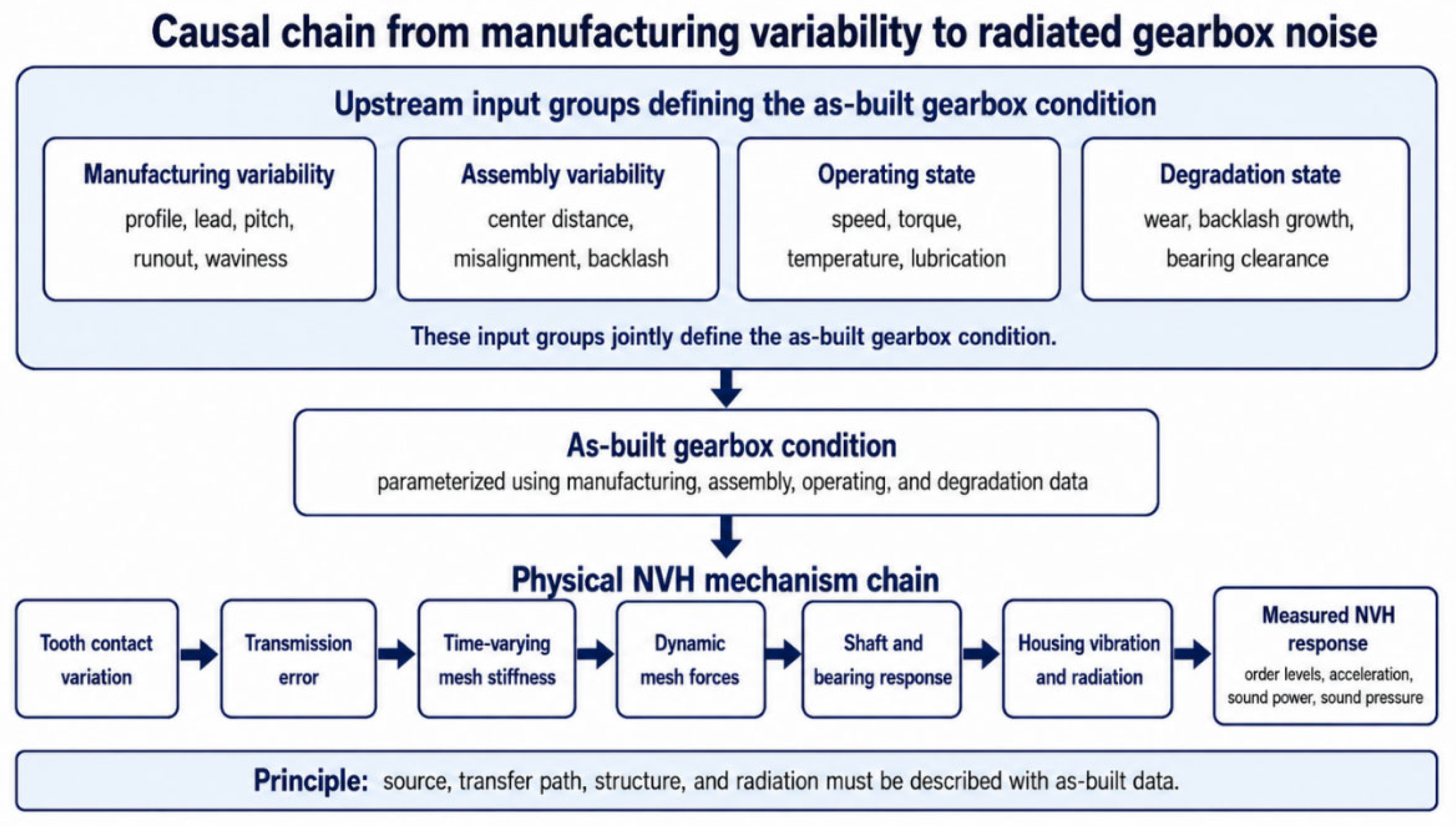
Figure 2.
Dual classification of gearbox NVH-relevant parameters according to physical origin and NVH function.
Figure 2.
Dual classification of gearbox NVH-relevant parameters according to physical origin and NVH function.
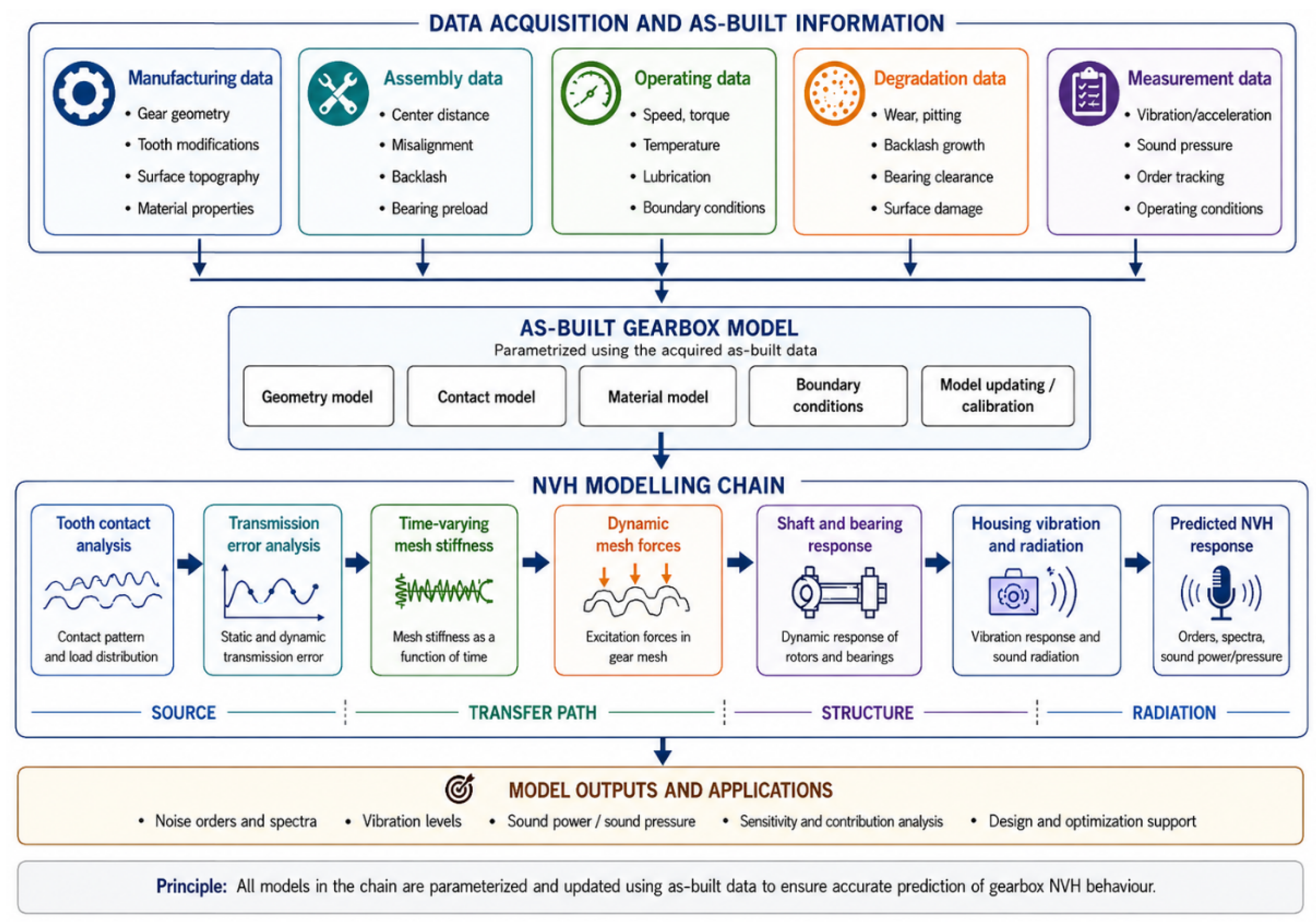
Figure 3.
Simulation-readiness levels for gearbox NVH modeling.
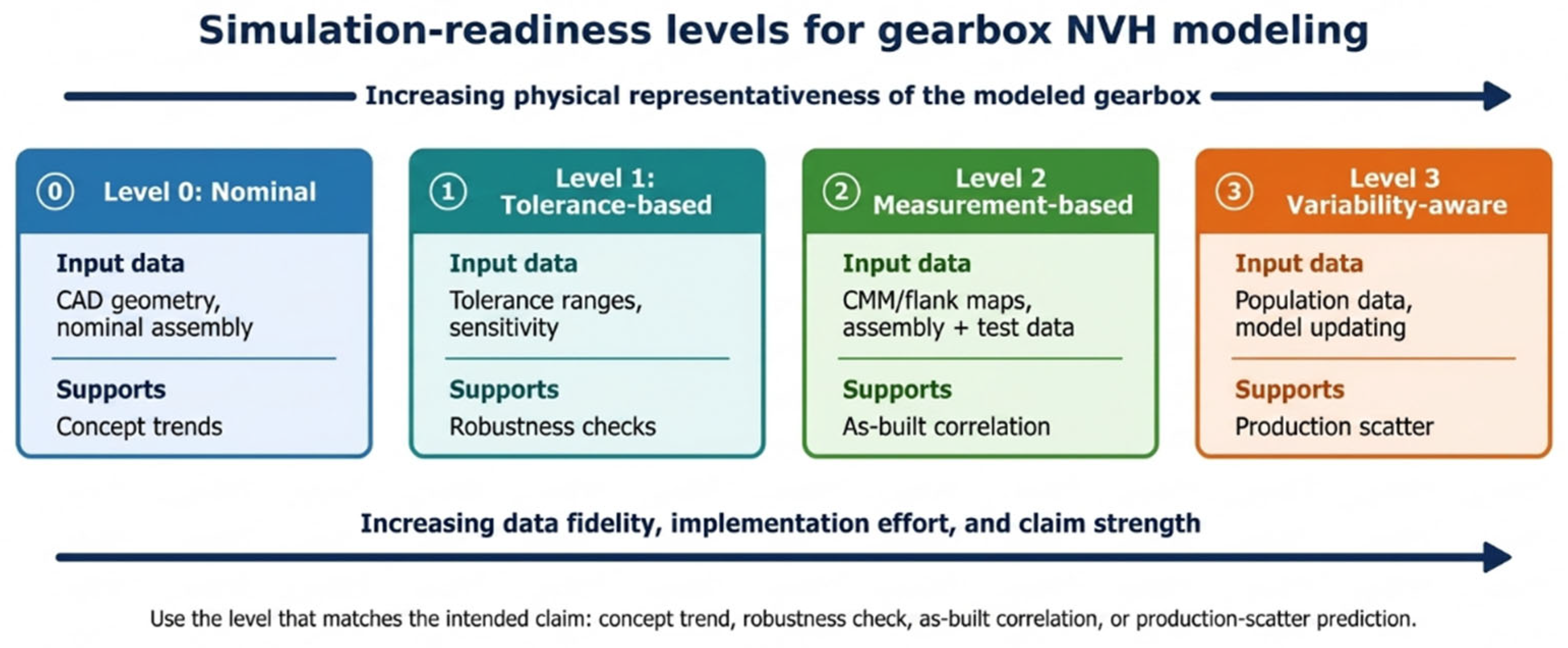
Figure 4.
Conceptual link between flank waviness, tonal concentration, and ghost-order risk.
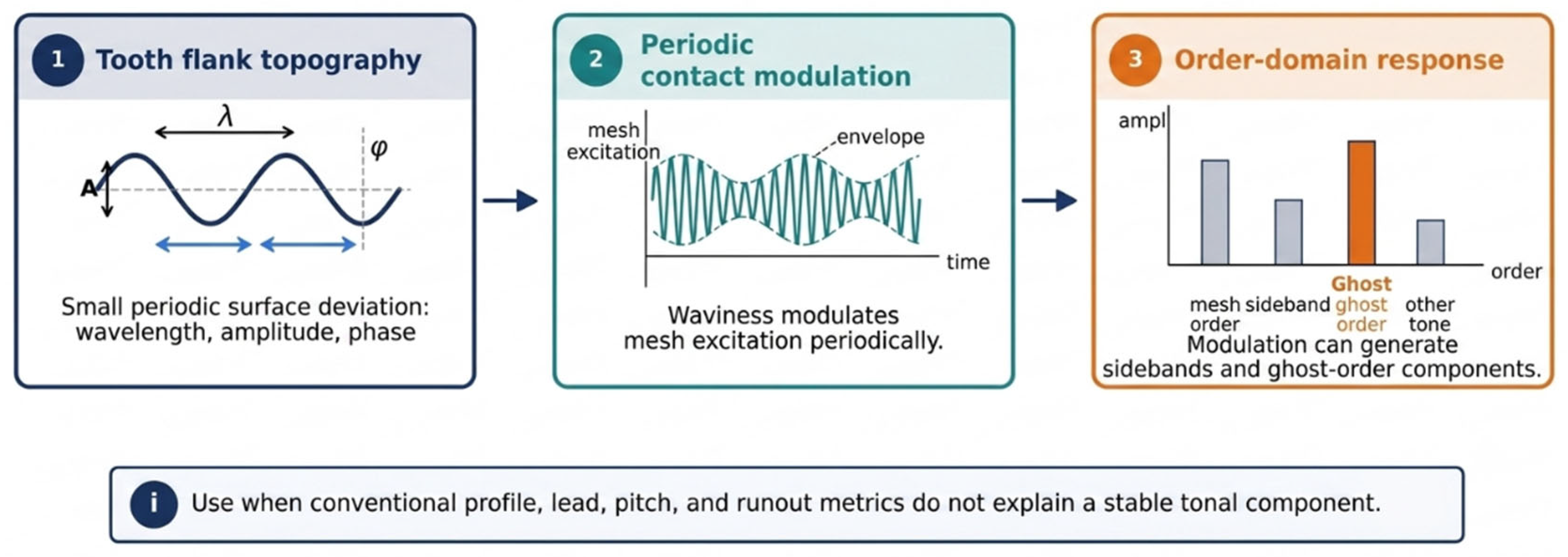
Figure 5.
Assembly alignment parameters influencing gear contact and bearing-force transmission.
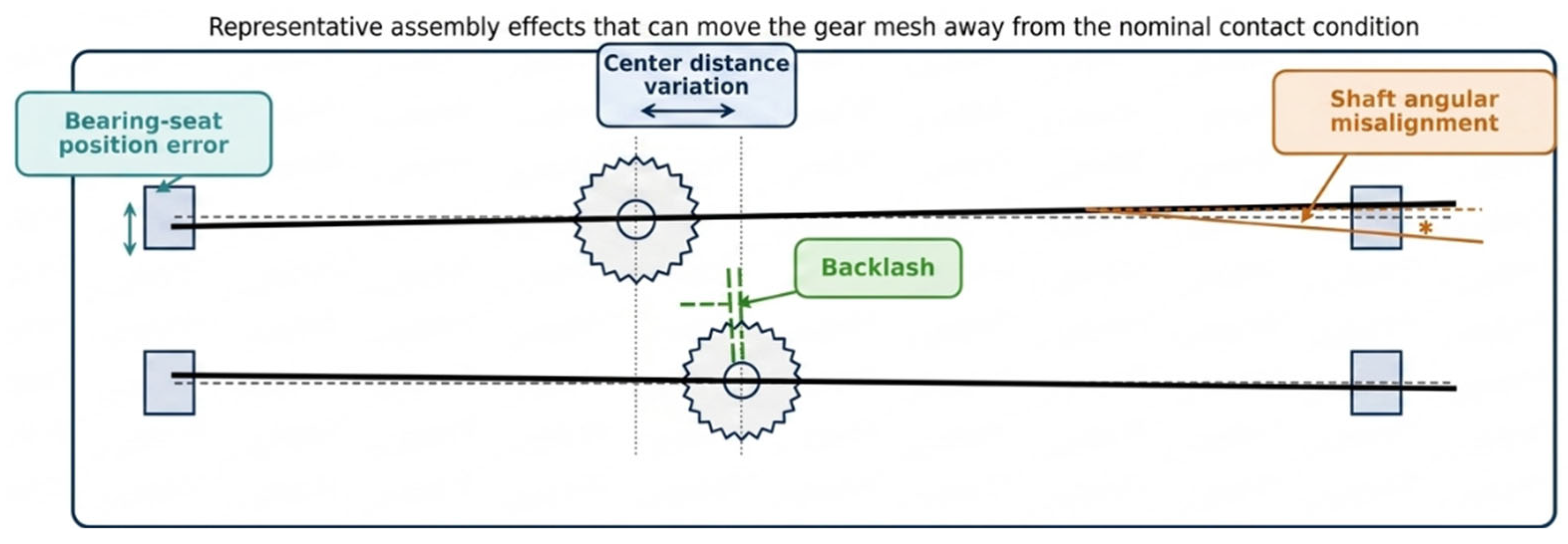
Figure 6.
Bearing data as NVH transfer-path inputs.
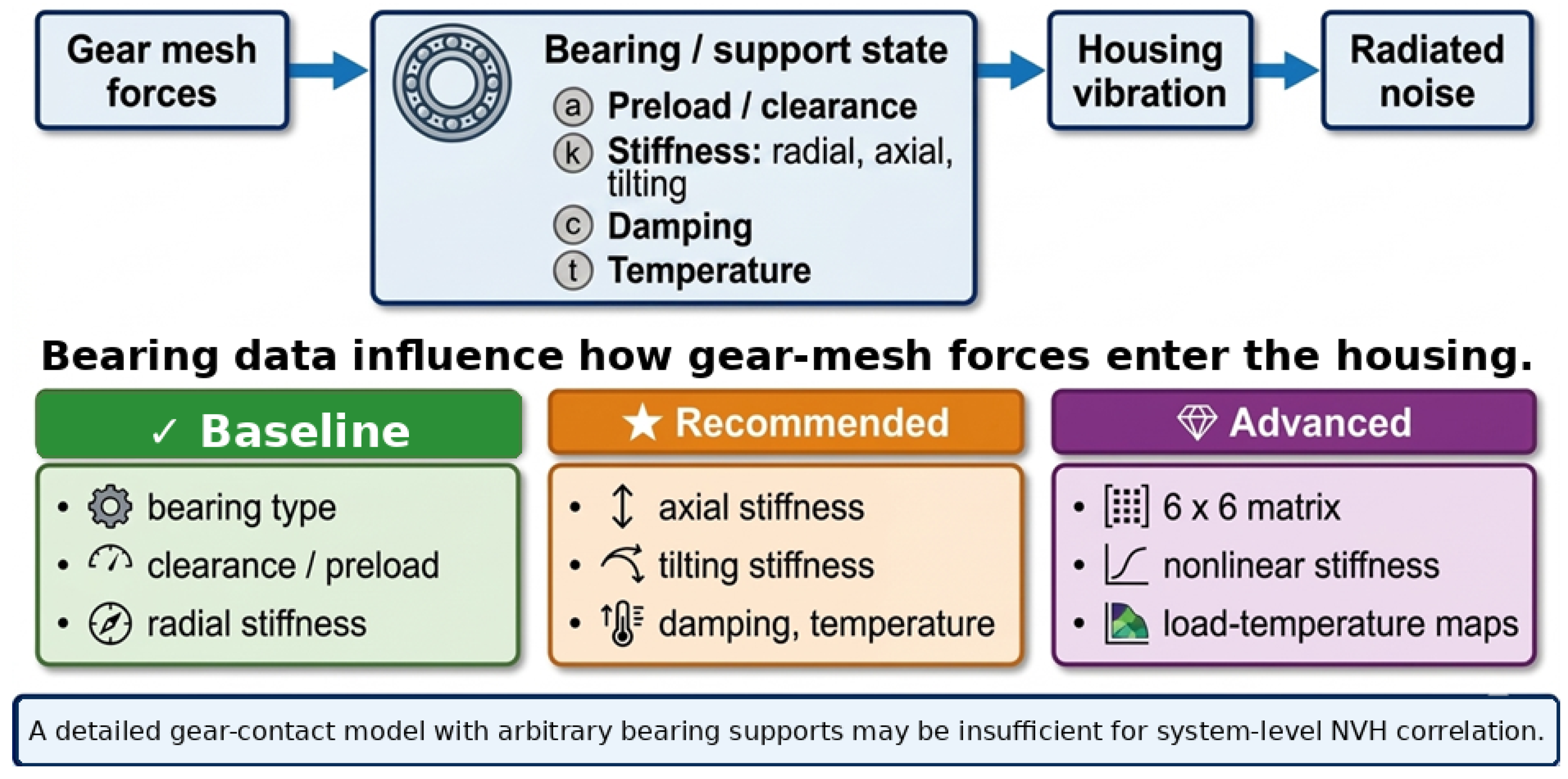
Figure 7.
Order-domain excitation map for gearbox and e-drive sources.
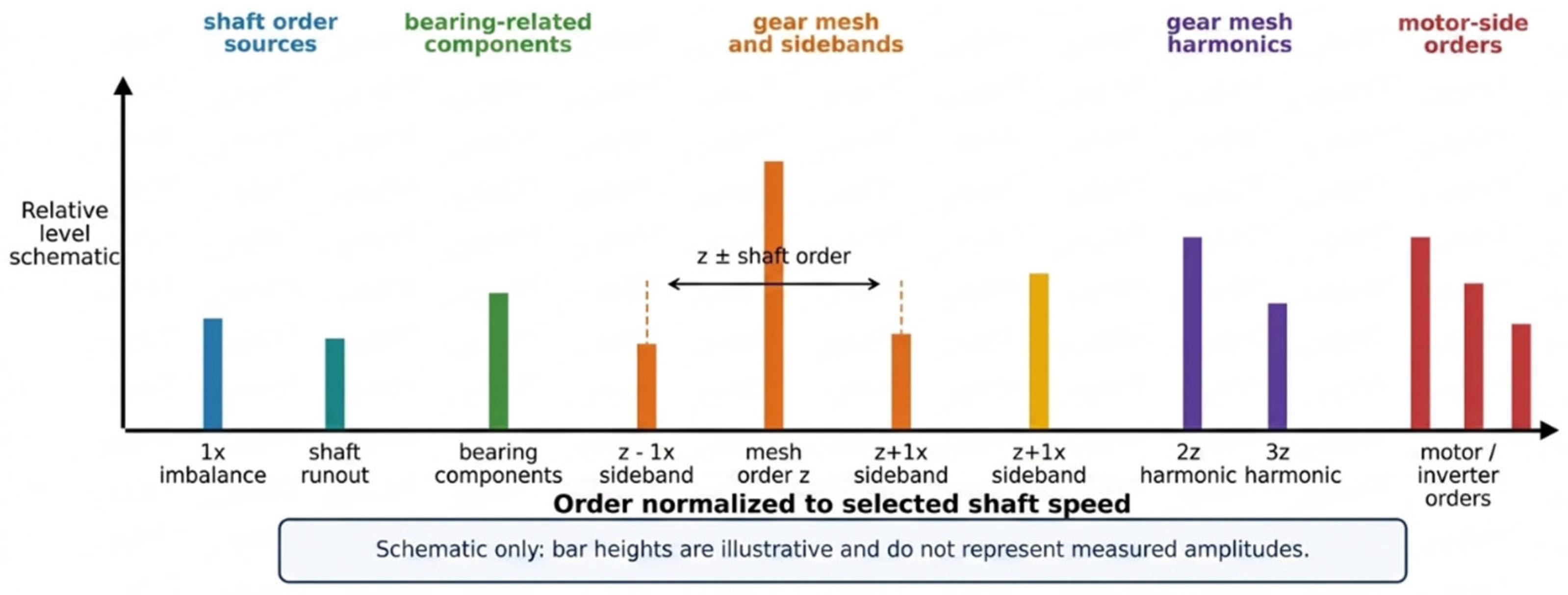
Figure 8.
Integrated LTCA-MBD-FEM-vibroacoustic workflow with structured manufacturing, assembly, operating, and degradation inputs.
Figure 8.
Integrated LTCA-MBD-FEM-vibroacoustic workflow with structured manufacturing, assembly, operating, and degradation inputs.
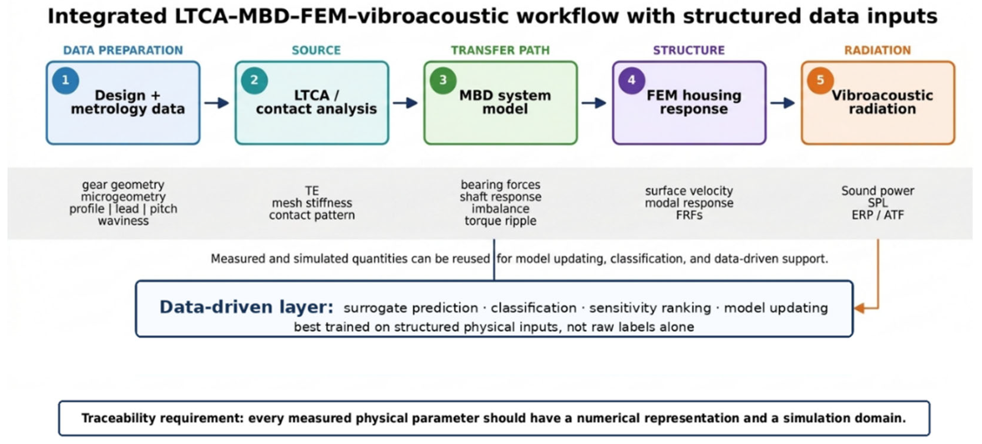
Table 1.
Manufacturing parameters relevant for gearbox NVH simulation.
| Parameter | Typical Unit | Typical Source | Main NVH Effect | Numerical Representation | Priority |
| Tooth number | – | CAD / drawing | Mesh-order definition | Gear pair definition | Baseline |
| Module | mm | CAD / drawing | Contact stiffness and geometry | Gear pair definition | Baseline |
| Pressure angle | deg | CAD / drawing | Force direction and tooth stiffness | Gear pair definition | Baseline |
| Helix angle | deg | CAD / drawing | Overlap ratio and axial force | Gear pair definition | Baseline |
| Face width | mm | CAD / drawing | Load distribution | Gear pair definition | Baseline |
| Tip relief | µm | Design / coordinate measuring machine (CMM)-based topography mapping | Loaded TE reduction | Profile modification curve | Baseline |
| Lead crowning | µm | Design / CMM | Misalignment robustness | Lead modification curve | Baseline |
| Profile deviation | µm | Gear inspection | TE variation | Flank surface offset | Baseline |
| Lead deviation | µm | Gear inspection | Face-load variation | Flank line correction | Baseline |
| Pitch error | µm / arcsec | Gear inspection | Mesh modulation and sidebands | Tooth-indexed error vector | Recommended |
| Cumulative pitch error | µm / arcsec | Gear inspection | Low-order modulation | Circumferential error vector | Recommended |
| Runout / eccentricity | µm | Gear inspection | Center-distance modulation | Eccentricity vector | Recommended |
| Tooth-to-tooth variation | µm | Tooth-wise inspection | Local excitation variation | Tooth-specific maps | Advanced |
| Surface roughness | Ra, Rz | Surface measurement | Contact and tribological effects | Roughness descriptor | Recommended |
| Flank waviness | µm, wavelength | Topography measurement | Ghost tones / non-classical tones | Surface waviness map | Advanced |
Table 2.
Surface-topography parameters relevant for gearbox NVH simulation.
| Parameter | Typical Source | Main NVH Effect | Numerical Representation | Priority |
| Waviness amplitude | Flank topography measurement | Tonal excitation strength | Periodic surface deviation | Recommended |
| Waviness wavelength | Surface measurement / process data | Order location and modulation | Spatial harmonic descriptor | Recommended |
| Waviness phase | Tooth-wise surface map | Tooth-to-tooth modulation | Phase-defined surface excitation | Advanced |
| Tooth-to-tooth topography variation | High-density flank measurement | Sidebands / tonal scatter | Tooth-specific flank maps | Advanced |
| Grinding signature | Process and surface data | Ghost-order risk | Process-related waviness pattern | Advanced |
| Honing topography | Process and surface data | Surface-related tonal effects | Surface descriptor or map | Advanced |
| Surface roughness | Surface profilometry | Contact and tribology influence | Statistical roughness descriptor | Recommended |
| Full flank topography | Optical / CMM scanning | Detailed excitation representation | Direct flank map | Advanced |
Table 10.
Tiered simulation-ready parameter framework for gearbox NVH simulation.
| Category | Baseline / Typical Parameter | Typical Source | Simulation Domain | Numerical Representation | Priority |
| Gear nominal geometry | Tooth number, module, pressure angle, helix angle, face width, center distance | CAD / drawing | LTCA, MBD | Parametric gear definition | Baseline |
| Gear microgeometry | Tip relief, root relief, crowning, lead correction | Design data / CMM | LTCA | Relief laws or flank maps | Baseline |
| Gear manufacturing deviations | Profile deviation, lead deviation, pitch error, runout | Gear inspection / CMM | LTCA, MBD | Surface offsets, pitch vectors, eccentricity | Baseline |
| Gear flank topography | Waviness amplitude, wavelength, tooth-specific variation | High-density flank measurement | LTCA, MBD | Surface map or spectral descriptor | Advanced |
| Assembly alignment | Center distance error, shaft misalignment, axial offset | Assembly metrology | LTCA, MBD | Shaft-axis offsets and rotations | Baseline |
| Backlash | Cold and, where possible, warm backlash | Inspection / assembly / test | LTCA, MBD | Nonlinear clearance / dead band | Baseline |
| Bearing data | Type, d/D/B, clearance or preload, radial stiffness | Supplier / assembly / test | MBD, FEM interface | Equivalent support stiffness | Baseline |
| Bearing transfer-path data | Axial stiffness, tilting stiffness, damping | Supplier / test / calculation | MBD, FEM interface | Directional stiffness-damping model | Recommended |
| Advanced bearing data | Load-dependent stiffness, 6 x 6 stiffness matrix | Supplier / test / bearing model | MBD, FEM interface | Nonlinear support law or matrix | Advanced |
| Shaft data | Geometry, support locations, mass, inertia | CAD / measurement | MBD, FEM | Rigid, beam, or flexible body | Baseline |
| Rotor excitation | Imbalance, eccentricity, runout | Balancing / metrology | MBD | Rotating force or eccentricity vector | Recommended |
| Electromechanical excitation | Torque ripple, electromagnetic force harmonics | Motor FE / inverter / test | MBD, FEM | Harmonic torque or force input | Recommended in e-drives |
| Housing data | Geometry, wall thickness, material, bearing seat positions | CAD / CMM / FE data | FEM | Structural FE model | Baseline |
| Housing variability | Wall-thickness variation, joint stiffness, damping | CT / test / EMA | FEM | Thickness field, joint elements, damping table | Recommended |
| Acoustic data | Radiation surfaces, receiver positions, sound power or pressure targets | Acoustic model / test | Vibroacoustic | Surface velocity input, receiver set | Recommended |
| Operating condition | Speed, torque, drive/coast state, temperature | Test plan / duty cycle | All domains | Operating map or time history | Baseline |
| Lubrication state | Oil type, viscosity, oil temperature | Specification / test | LTCA, MBD | Temperature-dependent properties | Recommended |
| Degradation state | Run-in, wear, backlash growth, bearing clearance growth | Inspection / durability test | LTCA, MBD | Updated geometry or support state | Recommended |
| Validation data | Order tracking, housing acceleration, microphone data, temperature, torque-speed logs | Test bench / vehicle test | Validation | Correlation targets | Baseline |
Table 11.
Mapping of NVH-relevant parameters to simulation domains.
| Parameter Group | LTCA / Contact Analysis | MBD | FEM | Vibroacoustic | Data-Driven Use |
| Gear macrogeometry | Direct gear definition | Gear pair definition | Indirect | Indirect | Geometry features |
| Gear microgeometry | Flank modification | Mesh excitation influence | Indirect | Indirect | Relief and crowning features |
| Profile and lead deviations | Surface deviation field | Equivalent TE / mesh excitation | Indirect | Indirect | Deviation statistics |
| Pitch error | Tooth-indexed pitch vector | Modulated excitation | Indirect | Indirect | Tooth-index features |
| Runout / eccentricity | Center-distance variation | Eccentricity excitation | Bearing force variation | Indirect | Runout amplitude and phase |
| Flank waviness | Surface map or harmonic descriptor | Equivalent excitation | Indirect | Indirect | Waviness descriptors |
| Assembly misalignment | Axis offset in contact model | Shaft-axis transformation | Support coordinate shift | Indirect | Alignment features |
| Backlash | Clearance in contact model | Nonlinear dead band | Indirect | Indirect | Clearance value / state |
| Bearing preload / clearance | Support condition if coupled | Preload-dependent stiffness | Interface condition | Indirect | Bearing state features |
| Bearing stiffness | Support stiffness if coupled | Bearing support model | Interface impedance | Indirect | Stiffness features |
| Shaft flexibility | Mesh alignment influence | Flexible shafts | Optional reduced body | Indirect | Shaft dynamic descriptors |
| Imbalance | Not usually direct | Rotating force | Interface force effect | Indirect | Imbalance magnitude / phase |
| Torque ripple | Load modulation | Harmonic torque input | Interface load effect | Indirect | Harmonic order features |
| Housing geometry | Not direct | Reduced flexible body if used | Structural FE geometry | Radiation surface | Modal features |
| Wall thickness | Not direct | Indirect | Thickness field | Radiation influence | Thickness descriptors |
| Structural damping | Not direct | Optional | Damping model | Affects radiation response | Identified damping features |
| Surface velocity | Not direct | Not direct | Response output | Main acoustic input | Vibroacoustic target |
| Acoustic transfer function | Not direct | Not direct | Optional post-processing | Acoustic sensitivity | Contribution feature |
| Speed and torque | Load condition | Operating profile | Load case definition | Receiver condition | Operating features |
| Degradation state | Updated flank geometry | Updated clearance / support | Updated stiffness / damping | Updated response | State label |
Disclaimer/Publisher’s Note: The statements, opinions and data contained in all publications are solely those of the individual author(s) and contributor(s) and not of MDPI and/or the editor(s). MDPI and/or the editor(s) disclaim responsibility for any injury to people or property resulting from any ideas, methods, instructions or products referred to in the content. |
© 2026 by the authors. Licensee MDPI, Basel, Switzerland. This article is an open access article distributed under the terms and conditions of the Creative Commons Attribution (CC BY) license (http://creativecommons.org/licenses/by/4.0/).
Copyright: This open access article is published under a Creative Commons CC BY 4.0 license, which permit the free download, distribution, and reuse, provided that the author and preprint are cited in any reuse.