

Submitted:
14 July 2026
Posted:
16 July 2026
You are already at the latest version
Abstract
Point to the manufacturing process of variable-section rectangular tube, a four-die radial extrusion process was designed in this article. The general deformation law was researched in two-dimensions, the influence of deformation parameters on the deformation results was explored, and the method by using the mold anti-deformation to eliminate the concave defects was proposed. For the tube parts with common thickness to diameter ratio, the corresponding optimal die arc degree is obtained through simulation and optimization. After that, the two-dimensional deformation law is applied to three dimensions, and the methods to eliminate the defect are carefully studied and successfully realized. Taking a variable-section rectangular tube as an example, the experiment was carried out. The experimental results were compared with the simulation results, and the accuracy of the simulation results and the feasibility of the process were verified.
Keywords:
variable-section rectangular tube
; radial extrusion
; anti-deformation
; optimization
1. Introduction
Variable-section rectangular tube parts [1] is a kind of hollow pipe part that is especially common in daily life and production. Its application is especially extensive. Compared with the ordinary rectangular tube, its greatest feature is its variable-section characteristics, which also determines the particularity and complexity of its forming process. The research works mostly aimed at the deformation of equal-section rectangular tubes [2,3,4,5]. The manufacturing processes of equal-section rectangular tubes include: roll forming, drawing forming, casting forming and welding forming, etc. Zhou Jie [6] established the drawing forming model of rectangular tube, simulated and analyzed, obtained the mechanism of wrinkling, and obtained the relationship between the drawing force and the taper of the die hole. A smoothing drawing method is put forward by Quan Guozheng [7]. It is found that a better stress state can be obtained by using the step-type core drawing, and the forming quality can be improved by using extrusion deformation to control the wall thickness. Fu Zhiqiang [8] established the analysis model and simulated the roll forming process, and obtained the distribution law of strain and stress. It is found that there is an obvious "eversion" and "varus" phenomenon on the end surface of the tube. Du Fengshan [9] established the relevant mathematical model, realized the roll design in the cold bending process of rectangular tubes, and carried out experiments. In addition, the law of metal flow and the distribution of residual stress were also studied.
The research of manufacturing technology for variable-section rectangular tubes is mainly dieless drawing process. Xia Hongyan [10,11] proposed a dieless forming method, which solved the problem of difficult plastic forming of tapered tubes, established a velocity model of dieless stretching, and studied the deformation mechanism. Mao Haoen [12] analyzed the influence of various parameters in dieless drawing deformation and conducted experimental verification. Obiko [13] investigated the plastic deformation behavior during forging of X20CrMoV121 steel by DEFORM and the influence of forging temperature on strain, stress and metal flow rate distribution during forging process was obtained. It was found that the drawing speed is affected by the feeding speed, billet size, conical tube shape and size, and the process parameters such as the distance between the hot and cold sources also have a certain influence on the drawing speed. The dieless drawing process is more demanding and the current stage is more experimental, so a new forming process needs to be developed.
2. Process Design
In this paper, a conical tube is used as blank and shaped into a variable-section rectangular tube. This process can be considered as a process of changing from a circle to a square in terms of two dimensions. In order to reduce the cost and complexity of the process, this paper adopts a four-die radial extrusion method. The position relationship between the die and the conical tube is as shown in Figure 1:
During the deformation process, the four dies move toward the center, and the radial extrusion force is applied to the tube blanks to force the tube blanks to flow radially and eventually become the shape of a rectangular tube. The process of converting the conical tube into a rectangular conical tube is realized.
The 3-D model of the blank tube and four dies were established by UG. Then, the models were imported into the Simufact software to carry out the numerical simulation. The FEM simulation model is shown in Figure 2. The tube is set as plastic and the four dies are set as rigid objects. The pressing speed of the dies is set to 10 mm/s, and the friction coefficient between the tube and the die is set to 0.1. The shape of the tube obtained by simulation is shown in Figure 3.
It can be seen from Figure 3 that a rectangular tube with a concave cross section is obtained from a circular tube. This is mainly due to the contact condition between the blank and the dies. At the beginning of the deformation, each die and blank has a line or point contact, and other parts are in a free state. Therefore, the stress at the point or line that is in contact with the die is the largest, and the deformation is first satisfied in the yield condition, then the deformation occurs in other locations. Therefore, the point or line that first contacted the die had the largest displacement, while the other parts had relatively small displacement. From the shape point of view, a concave shape was finally obtained.
The existence of concave has an important influence on the size and quality of rectangular tube. If the concave is serious, the product will even be scrapped. In order to eliminate the concave defect, the first thing that comes to mind is to add support inside the circular tube, that is, to use a mandrel inside the tube during the deformation process. However, the billet used in this paper is a tube blank with both ends closed, and the solid mandrel cannot be used. Taking into account the relatively large size of the blank, the use of hydraulic and sand is not very suitable. Therefore, according to the principle of the reverse compensation method, the shape of the die is changed, the original plane contact surface is modified into an arc contact surface, and the contact mode between the tube blank and the die is changed to eliminate the concave defect in the extrusion process. The shape of the improved die and blank is shown in Figure 4:
3. Influence of Various Factors on the Results of Deformation
In order to measure the degree of internal concave in the deformation, the concave degree was defined as:(Q is the absolute value of the distance between the highest point and the lowest point of the concave arc, as shown in Figure 5. D is the diameter of the blank tube. To improve the accuracy, measure the concave degree of the four sides, then take the average)
This section takes the planar die two-dimensional extrusion process as an example. The influencing factors in the study are the friction coefficient, thickness-diameter ratio, diameter of the pipe, die speed, and the material type. The single-factor variable method was used to simulate and study the influence rule in the following.
3.1. Influence of the Thickness-Diameter Ratio of the Billet on Deformation
Modeling and finite element software are used for the simulation analysis. The thickness-diameter ratio was set as 0.005, 0.02, 0.04, 0.06, 0.08, 0.10, 0.12 and 0.13 respectively. Study the influence of the blank thickness-diameter ratio on the deformation, the concave degree data obtained are shown in Figure 6.
With the increase of the thickness-diameter ratio, the change trend of the concave degree appears to increase first and then decrease. When the ratio of thickness-diameter increases to 0.12, there is basically no occurrence of concave, but such a thick tube has lost the significance of light weighting. In practical applications, the ratio of round tubes thickness-diameter is mostly between 0.02 and 0.1. However, in this range, the concave phenomenon on the tube in the radial extrusion process is serious. Therefore, how to prevent the occurrence of concave in the process of extrusion deformation is particularly important.
3.2. Influence of Tube Diameter on Deformation
Set the diameter of the round tube as follows: 100 mm, 200 mm, and 300 mm, and study the influence of diameter on the deformation. The obtained data on the concave degree are shown in Figure 7.
The concave degree decreases first and then increases with the increase of the diameter of the tube, but the maximum difference percentage is about 1.3%, and it can be considered that the concavity is almost the same. This shows that under the same thickness-diameter ratio, the diameter of the round tube does not influence the concave degree.
3.3. Influence of Friction on Deformation
Set the friction coefficient as follows: 0.05, 0.75, 0.1, 0.125 and 0.15 respectively. Then, study the influence of friction on the deformation. The obtained data on the concave degree are shown in Figure 8.
With the increase of the friction coefficient, the change trend of the concave degree increases first and then decreases gradually, but the maximum difference percentage is about 5%. The friction has little influence on the extrusion deformation of the tube.
3.4. Influence of Die Speed on Deformation
The die speed was set to 1 mm/s, 10 mm/s, 20 mm/s, and 50 mm/s, respectively, and the influence of die speed on the deformation was studied. The data on the concave degree obtained are shown in Figure 9.
With the increase of die speed, the change trend of the concave degree is gradually increasing, but the maximum difference percentage is about 3.4%. It can be considered that the die speed has no significant influence on the deforming results.
3.5. Influence of Material Type on Deformation
Different blank materials were selected: 20 steel, 45 steel, and 60 steel. The influence of the material type on the deformation was studied. The data on the concave degree obtained are shown in Figure 10.
With the increase of carbon content, the concave degree decreases gradually. The maximum difference percentage is about 22%. The material type has a significant influence on the deforming results. The greater the tensile strength and yield strength of the material, the smaller the concave after radial deformation.
In summary, it is found that the thickness-diameter ratio of the billet and the type of material are the main influencing factors. And the type of material for a part is determined. When the thickness-diameter ratio reaches 0.12, no concave defects occur, but the actual thickness-diameter ratio is between 0.02 and 0.1. Other methods must be used to avoid defects. In the following, an arc-shaped die is used instead of the planar die to study the influence of the arc-shaped die on the deformation results.
4. Optimization of the Optimal Die Arc Degree
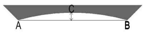
Defines the die arc degree as U for measuring the size of the die arc,,(R is the distance between the highest point of the arc C to the line segment AB, and D0 is the diameter of the pipe corresponding to the length AB of the die surface).
Figure 11.
Die arc degree.
In the analysis of two-dimensional deformation, if the final section of the forming part is square, the four dies are exactly the same. If the cross section is rectangular, the die of the long side and the short side are different, so the deformation of the two sections should be discussed separately.
4.1. Optimization of the Die Arc Degree of a Square Section Cone Tube
In the deformation of a square section cone tube, the four dies are exactly the same. For a tube blank with a certain thickness-diameter ratio, there is an optimal die arc degree, which could keep the flat state of the tube’s four sides after the extrusion deformation. In practice, the thickness-diameter ratio of the tube is mostly between 0.02 and 0.1. The optimum die arc degree corresponding to the tube with the thickness-diameter ratio of 0.02, 0.04, 0.06, 0.08, and 0.1 is optimized below.
A pipe material with a thickness-diameter ratio of 0.04 is used as the research object to model and simulate,the arc degree of the die is set to 0, 0.15, 0.2, 0.25, 0.4, 0.6 respectively. The influence of the die arc degree on the concave defects in the extrusion process is studied. The results of the deformation are as shown in Figure 12.
From the analysis of the above, we can see that when the die arc is small, every side of the square tube obtained is concave,and as the die arc degree increases, the tube concavity gradually decreases;When the die arc degree is 0.2, the sides of the square tube are approximately planar; when the arc degree continues to increase, the sides of the square tube begin to develop convexity, and the convexity increases as the die arc degree increases. In this simulation, the thickness-diameter ratio is 0.04, corresponding to an optimum die arc degree of 0.2.
Next, according to the same method to study the optimal die arc degree corresponding to other thickness-diameter ratio tubes, the following data are finally obtained. When the thickness-diameter ratio is 0.02, 0.04, 0.06, 0.08 and 0.1, the corresponding optimum die arc degree is 0.25, 0.2, 0.18, 0.15 and 0.1 respectively.
Figure 13.
Optimal die arc degree of different thickness-diameter ratios.
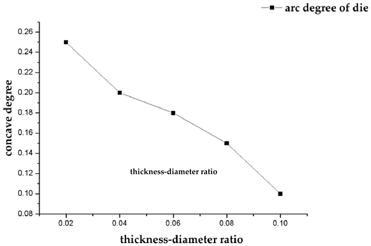
With the ratio of thickness-diameter increases, the optimal die arc degree gradually decreases. In actual applications, the ratio data is not necessarily the same, but as long as the ratio of thickness-diameter is within this range, the corresponding die arc degree can be estimated based on the above data.
4.2. Optimization of the Die Arc Degree of a Rectangular Section Cone Tube
For a rectangular section cone tube, the length and width are not the same, and the die arc must be different. There are countless kinds of aspect ratios, and you can't discuss every one of them. Here, three kinds of rectangular cross-section cone tubes with aspect ratios of 2:1, 3:2, and 4:3 are respectively optimized for die arc shape. The corresponding optimal die arc degree was obtained. The data is shown in the table below.

Table 1.
Optimal die arc degree of rectangular cone tube with aspect ratio 2:1.
| thickness-diameter ratio | 0.02 | 0.04 | 0.06 | 0.08 |
| optimal die arc degree | none | 0.4×0.2 | 0.4×0.1 | 0.4×0.1 |
Table 2.
Optimal die arc degree of rectangular cone tube with aspect ratio 3:2.
| thickness-diameter ratio | 0.02 | 0.04 | 0.06 | 0.08 |
| optimal die arc degree | 0.4×0.2 | 0.4×0.1 | 0.3×0.1 | 0.2×0.1 |
Table 3.
Optimal die arc degree of rectangular cone tube with aspect ratio 4:3.
| thickness-diameter ratio | 0.02 | 0.04 | 0.06 | 0.08 |
| optimal die arc degree | 0.4×0.2 | 0.4×0.1 | 0.3×0.1 | 0.2×0.2 |
For the cone tube extrusion deformation with an aspect ratio of 2:1 and a thickness -diameter ratio of 0.02, after a series of simulations, it has been found that the ideal forming effect is not always achieved. It is presumed that this is due to the fact that the thickness-diameter ratio is too low, and the stress level inside the thin wall is low, resulting in a decrease in the ability to resist deformation and deformation under a small force. In addition, the length of the long side is too large, so it is difficult to ensure a straight state. For the deformation of other rectangular conical tubes, an ideal forming effect was obtained, and the sides were kept in a straight state.
4.3. Three-Dimensional Simulation of a Conical Tube Into a Square Cone
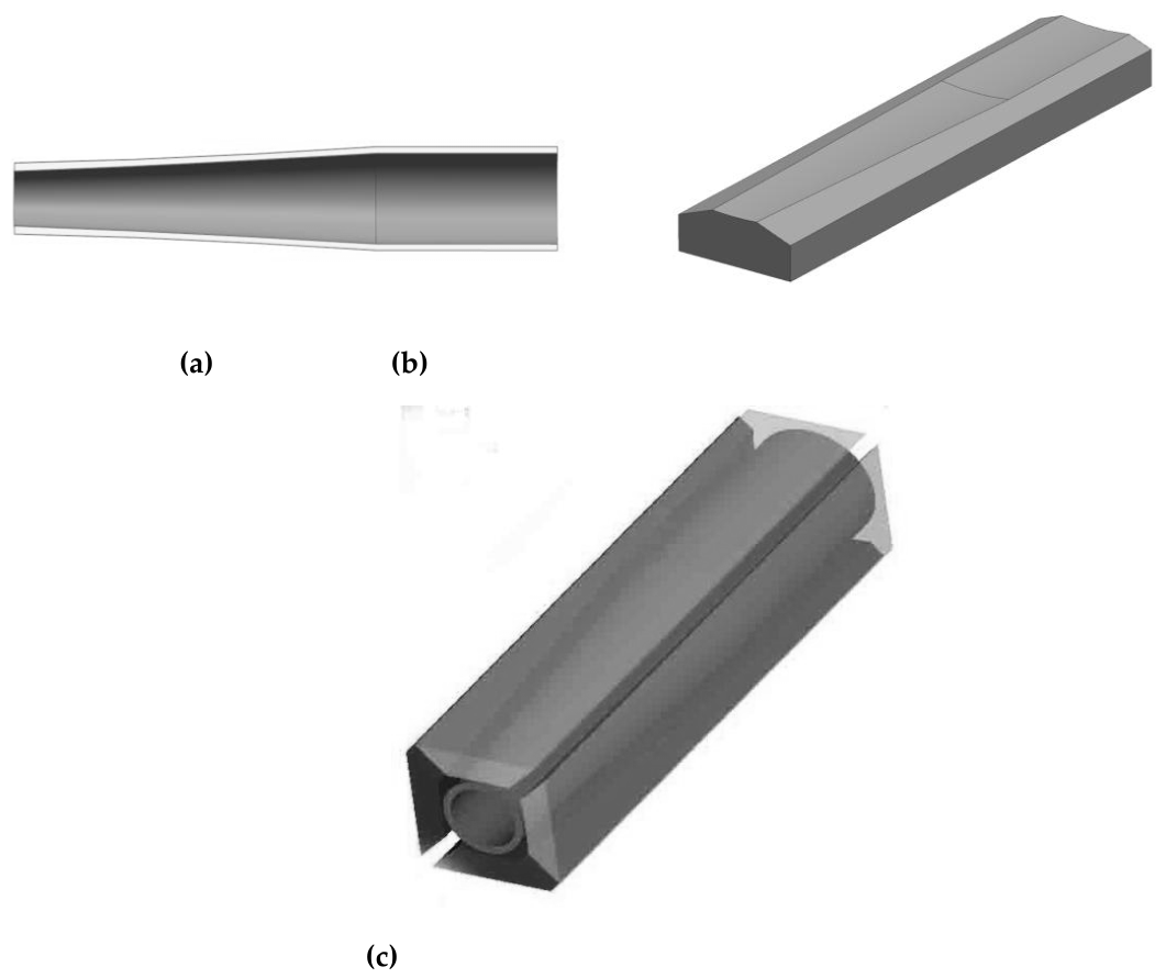
The above optimization of die arc shape is only a discussion of two-dimensional deformation. For a conical tube shaped as shown in Figure. 14(a) below, in this paper, the minimum and maximum end face die arc degree was determined according to the above rules. The middle part of the two end faces is determined by using a linear transition method. The die diagram and the model diagram are shown in Figure. 14(b)(c).
Figure 14.
Blank, die and simulation model.
According to the same deformation conditions, the deformation process of the plane die and the arc die is simulated. The deformation results obtained are shown in Figure 15.:
It can be found that the concave on the sides of the tube obtained by the simulation using the planar die are serious and have no practical application significance. The tube simulated by the arc die is flat on the four walls and has no obvious concave defects, which meet the requirements of rectangular tube fittings.
5. Experiments
The raw material tube used in this article is 20 steel, which belongs to high quality low carbon steel. The steel has low strength, good weldability, plasticity, and toughness. The mechanical properties of 20 steel are shown in Table 4.
In order to realize the radial movement of four dies, this paper designs a wedge structure and designs the die to be customized. The die structure is shown in Figure 16.
The die was mounted on a hydraulic press for experimentation; the installed image is shown in Figure 17:
The extrusion tests of the plane die and the arc die were performed separately. The comparison between the deformation results and the simulation results is shown in Figure 18 and Figure 19:
In order to quantify the comparison experiments and simulation results, the distances from the outermost edge of the tube to the center of the tube were measured, and measurements were taken at intervals of 20°. And because of the symmetry of the pipe, measures only the data from 0° to 180°, the data obtained is shown in Table 5 and Table 6. The changing trend is shown in Figure 20 and Figure 21:
In the analysis of the above data, the simulation of each end face is consistent with the experimental data, the error percentage is within 6.3%. In general, the simulation and experimental results are in good agreement, which verifies the reliability and accuracy of the numerical simulation.
6. Conclusions
In this paper, the manufacturing process of a rectangular tube with variable-section is designed. Mainly studied the extrusion process, discussed its general deformation rules and the elimination of defects, and obtained the following conclusions:
In the radial extrusion process, the two-dimensional deformation law was studied, and the influence of various parameters on the deformation process was obtained. Use mold anti-deformation to eliminate defects. For the square and rectangular section tubes, the optimal die arc degree corresponding to the thickness-diameter ratio was obtained. The two-dimensional deformation law was successfully applied to three-dimensional deformation.
The radial extrusion wedge die was designed, and the feasibility of the simulation and process was verified through experiments.
Author Contributions
Conceptualization: Xinhai Zhao and Chao Zheng.; methodology, Liangang Zhao.; software, Liangang Zhao.; validation, Xinhai Zhao. and Chao Zheng.; formal analysis, Lianggang Zhao.; investigation, Xinghui Wang.; resources, Xinhai Zhao.; data curation,Xinghui Wang; writing—original draft preparation, Lianggang Zhao; writing—review and editing, Xinhai Zhao.; visualization, Xinghui Wang.; supervision, Xinhai Zhao.; project administration, Xinhai Zhao.; funding acquisition, Chao Zheng. All authors have read and agreed to the published version of the manuscript.” Please turn to the CRediT taxonomy for the term explanation. Authorship must be limited to those who have contributed substantially to the work reported.
Funding
This research received no external funding.
Data Availability Statement
The data used to support the findings of this study are available from the corresponding author upon request.
Conflicts of Interest
The authors declare no conflicts of interest.
References
- Liu, Q. X.; Liu, C. Production of rectangular tube and its application in civil buildings in China [J]. World Build. Mater. 2002, 03, 81–82. [Google Scholar]
- Leu, Daw-Kwei. The Shaping of a Circular Tube into a Symmetric Square-Tube by Finite-Element Modeline [J]. J. Mater. Process. Technol. 2006, 178(1), 287–296. [Google Scholar] [CrossRef]
- Bayoumi, Laila S; Attia, Ahmed S. of the Forming Tool Load in Plastic Shaping of a Round Tube Into a Square Tubular Section [J]. J. Mater. Process. Technol. 2009, 209, 1835–1842. [Google Scholar] [CrossRef]
- Huang, Y. M.; Chen, W. C. Analysis of Tube Hydroforming in a Square Circular Tube [J]. Trans. Nonferros Met. Soc. China 2008, 18, 665–673. [Google Scholar] [CrossRef]
- Ma, J. L.; Chan, T. M.; Young, B. Material properties and residual stresses of cold-formed high strength steel hollow sections [J]. J. Constr. Steel Res. 2015, 152–165. [Google Scholar] [CrossRef]
- Zhou, J.; Song, Q. L.; Liao, X. Research on Drawing Process of Aluminum Rectangle Tube with High Internal Surface Quality [J]. China Mech. Eng. 2007, 18, 2252–2256. [Google Scholar]
- Quan, G. Z.; Wang, Y. X.; Ai, B. S. Design in the mandrel land and smoothing the. [CrossRef] [PubMed]
- deformation of rectangular tube drawing [J]. J. Chongqing Univ. 2009, 12, 1414–1418.
- Fu, Z. Q.; Du, F. S.; An, Z. J.; et al. Head Forming Mechanism of Rectangular Tube [J]. Iron Steel 2014, 02, 45–49. [Google Scholar]
- Du, F. S.; Fu, Z. Q.; Yu, H. Roll Flower Design and Forming Mechanism of Rectangular Tubes in Cold Roll Forming Process [J]. China Mech. Eng. 2016, 21, 2841–2845. [Google Scholar]
- Xia, H. Y.; Bian, Q.; Wu, D. Special Technique for Forming Big Inch Tapered Square Pipes [J]. J. Northeast. Univ. 2014, 01, 56–59. [Google Scholar]
- Xia, H. Y.; Luan, M. F.; Wu, D. New dieless drawing technique for making tapered pipe [J]. Forg. Stamp. Technol. 2009, 04, 25–27. [Google Scholar] [CrossRef]
- Mao, H. E.; Liu, X. F.; Qin, F.; et al. Theoretical and experimental analysis of a speed control model for continuous dieless drawingprocess of tapered pipes [J]. J. Univ. Sci. Technol. Beijing 2010, 05, 610–615. [Google Scholar]
- Obiko, J.O.; Mwema, F.M.; Bodunrin, M.O. Finite element simulation of X20CrMoV121 steel billet forging process using the Deform 3D software. SN Appl. Sci. 2019, 1, 1044. [Google Scholar] [CrossRef]
Figure 1.
Positional relationship between die and tube.

Figure 2.
FEM model.
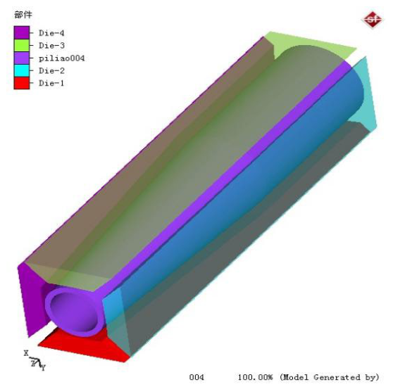
Figure 3.
Result from simulation.
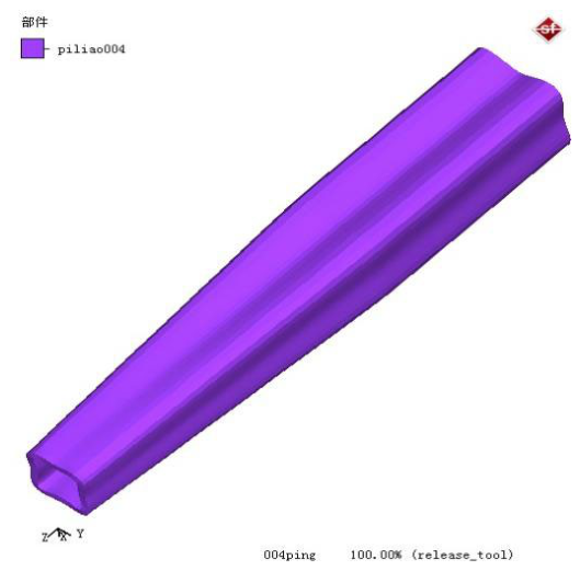
Figure 4.
Improved arc die and extrusion model.
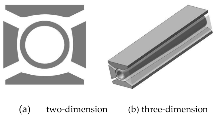
Figure 5.
Concave defects in blanks.
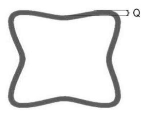
Figure 6.
Concave degree data.
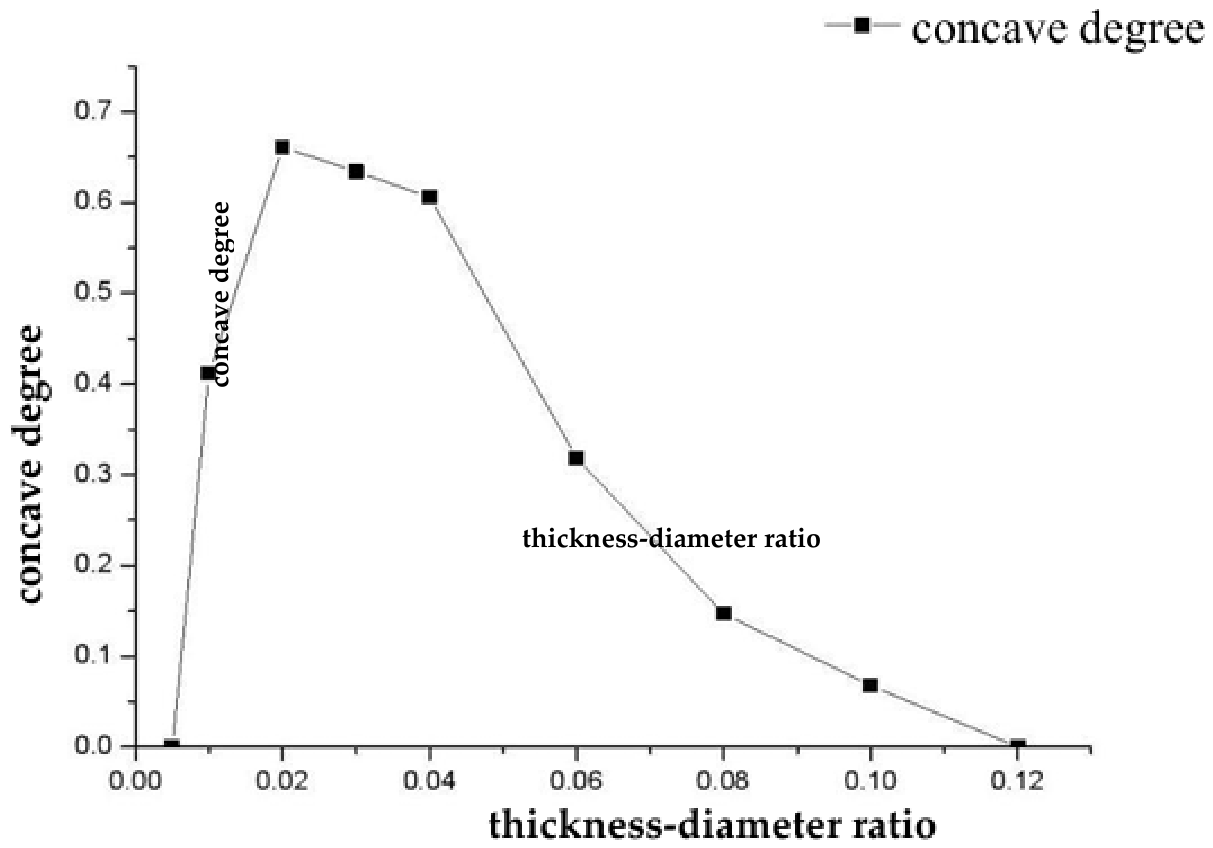
Figure 7.
Concave degree of different diameters.
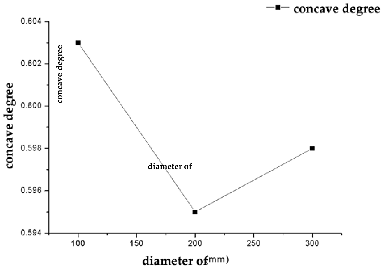
Figure 8.
Concave degree of different friction coefficients.
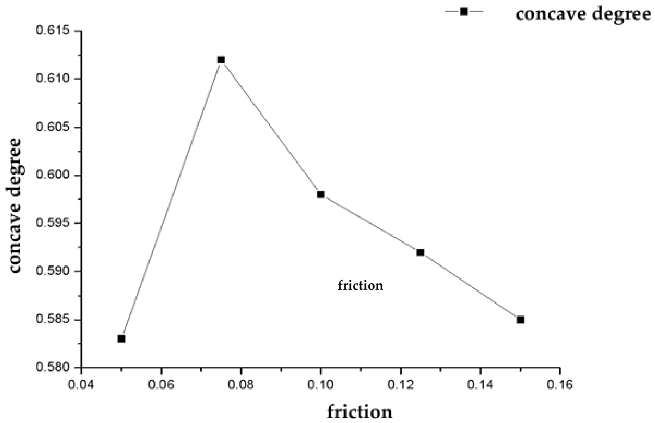
Figure 9.
Concave degree of different die speeds.
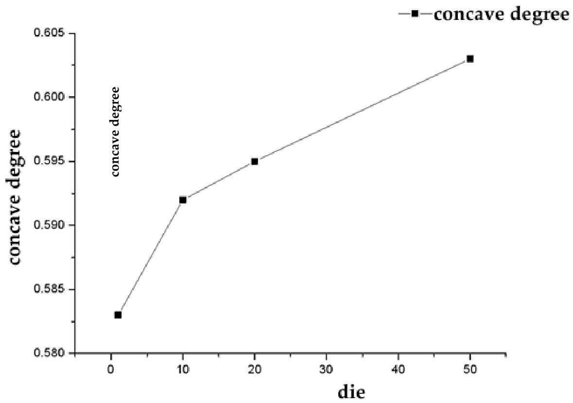
Figure 10.
Concave degree of different materials.
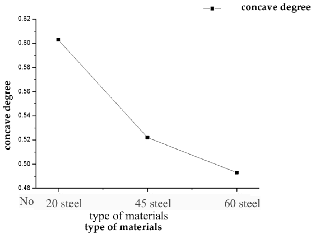
Figure 12.
Results of different die arc degree.
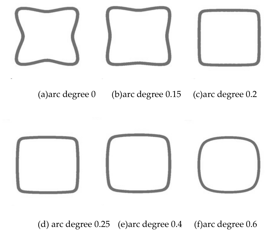
Figure 15.
Results of conical tube extrusion deformation.
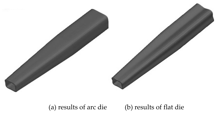
Figure 16.
Die of radial extrusion.
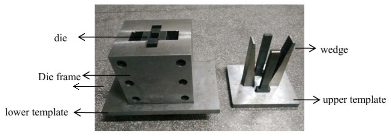
Figure 17.
Die installation diagram.
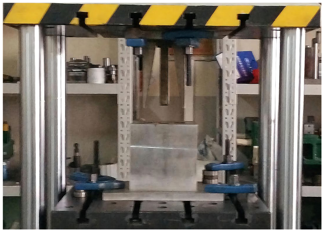
Figure 18.
Experimental and simulation results of plane dies.
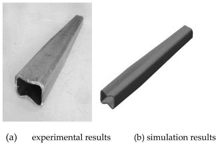
Figure 19.
Experimental and simulation results of arc dies.
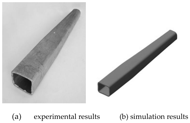
Figure 20.
Experimental and simulation results of plane dies.
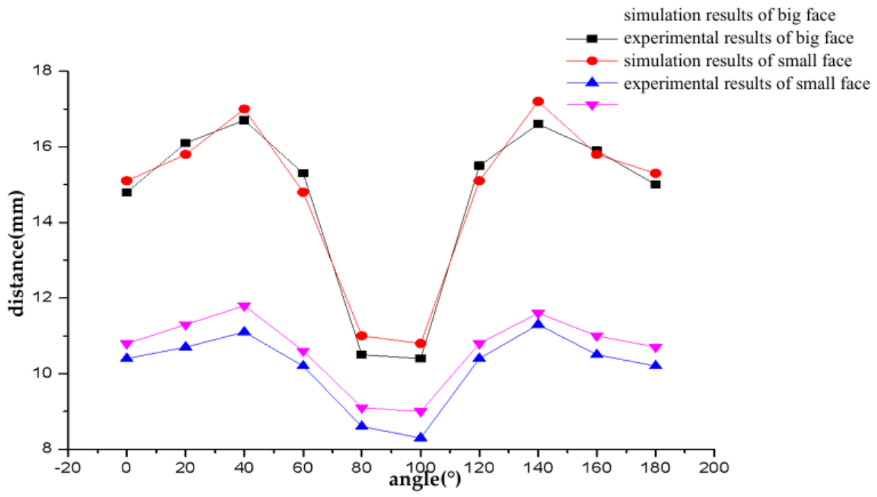
Figure 21.
Experimental and simulation results of arc dies.
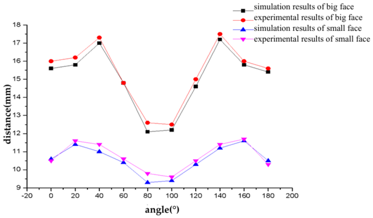
Table 4.
mechanical properties of 20 steel.
| material | mechanical property | |||
| tensile strength | yield strength | elongation | section shrinkage ψ | |
| 20 | 253-500 | 245 | ≥ 24 | ≥ 55 |
Table 5.
the distance with different angles obtained by simulation and experiment with plane dies.
| angle/° | 0 | 20 | 40 | 60 | 80 | 100 | 120 | 140 | 160 | 180 | |
| position | |||||||||||
| simulation results of big face /mm | 14.8 | 16.1 | 16.7 | 15.3 | 10.5 | 10.5 | 15.5 | 16.6 | 15.9 | 15.0 | |
| experimental results of big face /mm | 15.1 | 15.8 | 17.0 | 14.8 | 11.0 | 10.8 | 15.1 | 17.2 | 15.8 | 15.3 | |
| Error percentage | 2.0% | 1.9% | 1.8% | 3.3% | 4.8% | 2.9% | 2.6% | 3.6% | 1.0% | 2.0% | |
| simulation results of small face /mm | 10.4 | 10.7 | 11.1 | 10.2 | 8.6 | 8.3 | 10.4 | 11.3 | 10.5 | 10.2 | |
| experimental results of small face/mm | 10.8 | 11.3 | 11.8 | 10.6 | 9.1 | 9.0 | 10.8 | 11.6 | 11.0 | 10.7 | |
| Error percentage | 3.8% | 5.6% | 6.3% | 3.9% | 5.8% | 8.4% | 3.8% | 2.7% | 4.8% | 4.9% | |
Table 6.
the distance with different angles obtained by simulation and experiment with a curve die.
| angle/° | 0 | 20 | 40 | 60 | 80 | 100 | 120 | 140 | 160 | 180 | |
| position | |||||||||||
| simulation results of big face /mm | 15.6 | 15.8 | 17.0 | 14.8 | 12.1 | 12.2 | 14.6 | 17.2 | 15.8 | 15.4 | |
| experimental results of big face /mm | 16 | 16.2 | 17.3 | 14.8 | 12.6 | 12.5 | 15.0 | 17.5 | 16.0 | 15.6 | |
| Error percentage | 2.6% | 2.5% | 1.8% | 0% | 4.1% | 2.5% | 2.7% | 1.7% | 1.3% | 1.3% | |
| simulation results of small face /mm | 10.6 | 11.4 | 11.0 | 10.4 | 9.3 | 9.4 | 10.3 | 11.2 | 11.6 | 10.5 | |
| experimental results of small face/mm | 10.5 | 11.6 | 11.4 | 10.6 | 9.8 | 9.6 | 10.5 | 11.4 | 11.7 | 10.3 | |
| Error percentage | 1.0% | 1.8% | 3.6% | 1.9% | 5.4% | 2.1% | 1.9% | 1.8% | 1.0% | 1.9% | |
Disclaimer/Publisher’s Note: The statements, opinions and data contained in all publications are solely those of the individual author(s) and contributor(s) and not of MDPI and/or the editor(s). MDPI and/or the editor(s) disclaim responsibility for any injury to people or property resulting from any ideas, methods, instructions or products referred to in the content. |
© 2026 by the authors. Licensee MDPI, Basel, Switzerland. This article is an open access article distributed under the terms and conditions of the Creative Commons Attribution (CC BY) license (http://creativecommons.org/licenses/by/4.0/).
Copyright: This open access article is published under a Creative Commons CC BY 4.0 license, which permit the free download, distribution, and reuse, provided that the author and preprint are cited in any reuse.