
Submitted:
14 July 2026
Posted:
15 July 2026
You are already at the latest version
Abstract
Tooth loss and alveolar bone resorption caused by dental caries and periodontal disease remain major clinical chal-lenges that compromise oral function. Tissue engineering approaches based on biocompatible scaffolds have emerged as promising strategies for bone regeneration; however, the influence of fabrication methods on scaffold performance re-mains unclear. This study developed hydroxyapatite/poly(lactic-co-glycolic acid)/chitosan (HAp/PLGA/CS) scaffolds using freeze-drying and 3D-printing techniques and evaluated their physicochemical, biological, and biomechanical properties.Scaffold morphology, porosity, degradation behavior, and mechanical properties were characterized, while biocompatibility and osteogenic potential were assessed using human dental pulp stem cells (hDPSCs). Finite element analysis (FEA) using COMSOL Multiphysics® was performed to evaluate scaffold behavior under simulated dental implant loading conditions.Both fabrication methods produced biocompatible scaffolds that supported cell viability and early osteogenic responses. The 3D-printed scaffolds exhibited significantly higher cell viability than freeze-dried scaf-folds, reaching approximately 85% in the 50% infill group compared with 50% in the freeze-dried group. Microstructural analysis revealed interconnected hierarchical porosity, including macro, micro, and submicron scale pores. Although the 50% infill scaffold showed the highest cell viability, the 70% infill scaffold demonstrated the most favorable osteo-genic profile, with enhanced RUNX2 and OSX expression. Both scaffold types exhibited degradation profiles compatible with early bone regeneration. FEA simulations indicated that further mechanical optimization is required to improve load transfer and reduce deformation at the implant–scaffold interface. Overall, HAp/PLGA/CS scaffolds showed prom-ising potential for bone tissue engineering. Among the formulations evaluated, 3D-printed scaffolds provided superior architectural control and enhanced osteogenic performance, although additional mechanical refinement is needed before clinical translation.
Keywords:
bone tissue engineering
; 3D printing
; human dental pulp stem cells (hDPSCs)
; finite element analysis (FEA)
; dental implants
; hydroxyapatite/PLGA/chitosan
1. Introduction
Dental caries and periodontal disease are two of the most prevalent oral pathologies worldwide [1]. Both conditions can lead to partial or total tooth loss, significantly affecting masticatory function, facial esthetics, and dietary habits, while also inducing alveolar bone resorption that adversely affects general health of the patient [1,2,3]. Although conventional prostheses are widely used to treat tooth loss, they often have long-term complications, including soft tissue hyperplasia, ulcerations, altered taste perception, and loss of proprioception [4]. Consequently, osseointegrated dental implants have revolutionized modern dentistry and markedly improved patient quality of life [5,6]. However, post-extraction bone remodeling frequently results in horizontal and vertical ridge defects, compromising implant esthetics and functionality while complicating placement. Restoring the dimensions of the alveolar ridge to ensure at least 1.5 to 2.0 mm bone thickness around the fixture is essential to achieve successful osseointegration [7].
Various techniques are used to regenerate bone tissue and meet these clinical requirements. Although autologous bone grafts remain the gold standard, their clinical utility is limited by limited donor-site availability and the need for secondary surgical procedures [8]. Bone tissue engineering has emerged as a promising alternative, focusing on regeneration through the development of functional biological substitutes [8,9]. This discipline relies on a fundamental triad: growth factors, cells, and scaffolds. Scaffolds provide structural templates that support cell development and subsequent tissue formation. To be effective, they must be biocompatible, have interconnected porosity and adequate mechanical strength, and mimic the natural three-dimensional architecture of the extracellular matrix (ECM) [10].
In recent years, three-dimensional (3D) printing has enabled precise control over scaffold architecture, improving both mechanical performance and cytocompatibility. This technology also facilitates the incorporation of polymeric hydrogels, such as collagen, fibrin, and chitosan, which are essential to tailor the rheological, chemical, mechanical, and biological properties to better replicate the native ECM [11,12,13,14,15]. In parallel, bioceramics naturally found in bone tissue, including hydroxyapatite (HAp) and beta-tricalcium phosphate (β-TCP), promote osteogenesis by creating an ion-rich bioactive microenvironment while reinforcing the mechanical properties of composite scaffolds [16,17]. The combination of HAp with synthetic polymers, such as poly(lactic acid) (PLA) or poly(lactic-coglycolic acid) (PLGA), has been shown to enhance cell adhesion, proliferation, and osteoinductive capacity [18,19,20,21]. Similarly, blending HAp with chitosan (CS) produces scaffolds with favorable porosity, biomimetic characteristics, biocompatibility, biodegradability, and intrinsic antimicrobial properties [22,23].
Despite these advances, the comparative biological and mechanical performance of composite scaffolds HAp/PLGA/CS manufactured using different techniques remains insufficiently understood in the context of oral bone regeneration [18,19,20,21,22,23]. In addition, their ability to withstand functional loads associated with dental implants has not been thoroughly investigated. Evaluating their mechanical behavior is essential to assess the feasibility of simultaneous scaffold and implant placement, a strategy that could significantly reduce rehabilitation times.
In this study, HAp/PLGA/Cs scaffolds were developed using two distinct fabrication techniques: freeze-drying [24] and 3D printing [25]. Their physical, structural and mechanical properties were characterized with respect to porosity and elemental composition. Biocompatibility was assessed using human dental pulp stem cells (hDPSCs) due to their robust osteogenic differentiation potential [26,27,28]. Finally, to predict the ability of the scaffolds to withstand the functional loads associated with oral implants, specifically the Brånemark™ oral implant system [29], and to explore the potential reduction of oral rehabilitation time through simultaneous scaffold and implant placement, finite element method (FEM) simulations were performed using COMSOL Multiphysics® [30]. FEM is a computational approach that divides a complex three-dimensional structure into small elements and numerically solves the governing equations. In this study, the simulations incorporated scaffold geometry, material properties, including elastic modulus, density, and Poisson’s ratio, and boundary conditions representing fixed regions and load-bearing surfaces. The resulting stress and deformation maps allowed the identification of critical regions, elastic limits, and potential failure zones, providing information on the mechanical viability of the proposed scaffold–implant system.
2. Materials and Methods
The experimental design integrated the synthesis of HAp/PLGA/CS composites, scaffold fabrication through freeze-drying and 3D printing, and comprehensive structural characterization. In vitro biocompatibility was evaluated using human dental pulp stem cells (hDPSCs), while mechanical performance under functional loading conditions was assessed through combined stiffness (Young’s modulus), compressive strength, and microhardness measurements, complemented by finite element analysis (FEA).
2.1. Development of HAp/PLGA/CS Shards
2.1.1. Freeze-Drying Method
Hydroxyapatite (HAp) was obtained from avian eggshells through a combined thermal and chemical treatment according to the protocol reported by Sequeda et al. (2012) [31], which allows the conversion of calcium carbonate (CaCO3) into HAp. Poly(lactic-co-glycolic acid) (PLGA; 50:50 ratio, Mw 24,000–38,000; Ref: 719870) and high-molecular-weight chitosan (CS; Mw 310,000-35,000 Da; Ref: 419419) were purchased from Sigma-Aldrich® (USA).
Using these components, hydroxyapatite/poly(lactic-co-glycolic acid)/chitosan (HAp/PLGA/CS) composites were synthesized. Cylindrical scaffolds (7mm × 20mm) were manufactured using the freeze-drying technique described by Wang [32] and Raman [24]. During this process, optimal material proportions were established, and the resulting scaffolds were evaluated in terms of their physical and structural properties.
2.1.2. 3D Printing Method
To fabricate HAp/PLGA/CS scaffolds by 3D printing, xanthan gum was incorporated into the previously optimized composite formulation (derived from freeze-dried scaffolds) to act as a rheological modifier, improving viscosity and printability.
The sheets were printed with a BioX bioprinter (Cellink, Sweden) under optimized conditions: extrusion pressure of 20 kPa, printing speed of 2.0 mm/s, nozzle and syringe temperature of 36 °C, print bed temperature of 40 °C, nozzle diameter of 0.580 mm, and an initial layer stabilization time of 5 min.
To investigate the effect of internal architecture, the printing parameters were adjusted to produce scaffolds with three infill densities (50%, 60%, and 70%), enabling controlled variation in porosity and filament distribution. Following fabrication, all scaffolds underwent a final freeze-drying step to remove the solvent phase, resulting in a stable and highly porous structure that mimics trabecular bone.
2.2. Physical and Structural Characterization of Both Types of Shackles
Following fabrication, the HAp/PLGA/CS scaffolds produced by both methods were evaluated in terms of their physical and structural properties, including porosity (pore size, distribution, density, and interconnectivity) as well as mechanical and chemical characteristics.
2.2.1. Total Porosity
Total porosity was determined using the liquid displacement method [33]. This method is based on the ratio between the volume of absorbed fluid and the total volume of the scaffold, as defined by Equation [1]:
where is the initial volume of ethanol (ACS, ISO, Reag. Ph Eur; Merck), is the volume of ethanol with the scaffold immersed, and is the residual ethanol volume after scaffold removal.
2.2.2. Pore Distribution and Interconnectivity
The composite porosity was further analyzed based on morphological features using scanning electron microscopy (SEM). The samples were coated with a 15 nm gold layer using a Baltec SCD 050 system. The imaging was performed at an accelerating voltage of 10 kV under high-vacuum conditions and at multiple magnifications to evaluate different regions of the scaffold. Quantitative analysis of the pore size distribution and interconnectivity was performed using the MATLAB software R2023a [34]. SEM micrographs were converted to grayscale images to determine the diameter and depth of the pores, incorporating the pixel-to-micrometer conversion factor for accurate dimensional analysis. Subsequently, statistical analysis was conducted to evaluate pore density and interconnectivity.
2.2.3. Mechanical and Chemical Characterization
The structural properties of the scaffolds, including hardness and elasticity, were initially estimated on the basis of the stoichiometric composition of CaO and HAp, followed by the analysis of the final tri-composite material. Elemental composition was determined by X-ray fluorescence (XRF) spectroscopy using a Shimadzu XRF-7000 instrument.
The relationship between porosity, composition and mechanical performance was then evaluated, focusing on stiffness (Young’s modulus), compressive strength, and microhardness. Mechanical testing was conducted using a universal testing machine (MRC UTM-65A) at a loading rate of 0.5 N/s.
Young’s modulus and compressive strength were derived from stress–strain curves. Microhardness measurements were performed using a Vickers microhardness tester (Laizhou Lyric) with a square-based pyramidal indenter applied at a penetration rate of 20 µm/s and a dwell time of 15 s.
The Vickers hardness number (HV) was calculated using Equation [2]:
where F is the load expressed in kilograms-force (kg-f), As is the surface area of the indentation (mm2), and HV is the Vickers microhardness number expressed in units of pressure.
2.2.4. Energy-Dispersive X-Ray Spectroscopy (EDX) Analysis
Elemental analysis was also performed using energy-dispersive X-ray spectroscopy (EDX) coupled to a TESCAN LYRA3 field-emission scanning electron microscope (FE-SEM). This technique is based on the emission of characteristic X-rays generated by the interaction between the incident electron beam and the sample. EDX spectra were collected from the same regions previously examined by SEM to ensure consistency between the morphological and compositional analyzes.
2.3. Biocompatibility Evaluation of HAp/PLGA/CS Supports
2.3.1. hDPSC Cell Culture
The biocompatibility of the scaffold was evaluated using human dental pulp stem cells (hDPSC; PoieticsTM, Lonza), cultured according to the manufacturer’s instructions in DPSC BulletKitTM PT-4516 medium (Lonza). A vial containing 5.0 × 10⁵ cells was divided into two 25 cm2 culture flasks (2.5 × 10⁵ cells per flask).
Culture medium consisted of 440 mL of base medium supplemented with 50 mL of DPSCGS, 10 mL of L-glutamine, 5 mL of ascorbic acid, and 0.5 mL of gentamicin/amphotericin. The cells were kept at 37 °C in a humidified atmosphere containing 5% CO2, and the medium was refreshed every 3 days.
Upon reaching approximately 80% confluence, cells were subcultured by trypsinization followed by centrifugation at 1,800 rpm for 3 min. Cell concentration was determined using a Neubauer counting chamber according to Equation [3]:
Cells in passage 5 were subsequently seeded onto scaffolds for biocompatibility evaluation.
2.3.2. Biocompatibility Assessment of hDPSC-Seeded Sheets
The columns were sectioned into cylindrical specimens (4 mm in diameter and 2 mm in height) using a dermal biopsy punch and placed in 24-well plates. The samples were sterilized under ultraviolet (UV) light in a laminar flow hood for 15 min.
A total of 1.0 × 10⁵ cells per well were seeded onto the scaffolds in culture medium. Freezed-dried scaffolds were designated as L1 and L2, while 3D-printed scaffolds were categorized according to infill density (50%, 60%, and 70%).
Cell adhesion, viability, proliferation, and differentiation were evaluated at 3, 7, 14 and 21 days for all 3D-printed groups, while gene expression analysis (RT-qPCR) was performed only for 60% and 70% infill groups.
Lyophilized bovine bone (HB; Fundación Cosme y Damián) was used as an osteogenic reference material and scaffold-free hDPSCs served as a control group for relative gene expression analysis. [35].
2.3.3. Cell Viability Analysis by Fluorescence Microscopy
After 7 days of culture, cell viability and adhesion were assessed using the LIVE/DEAD TM viability/cytotoxicity kit (Invitrogen TM, USA) following the manufacturer’s protocol. The samples were incubated for 10 min at 37 °C and subsequently observed using an Olympus IX71 fluorescence microscope.
The quantification of viable and non-viable cells was performed using ImageJ software. All types of scaffolds (freeze-dried and 3D-printed with 50%, 60%, and 70% infill) were analyzed in triplicate.
In addition, cytotoxicity was evaluated using a lactate dehydrogenase (LDH) colorimetric assay (Roche). After 7 days, the cell culture supernatants were collected and the absorbance was measured using a Tecan® microplate reader. LDH results were analyzed independently from fluorescence imaging data.
2.3.4. Osteogenic Gene Expression Analysis
After 7 days of culture, osteogenic gene expression was evaluated. Total RNA was extracted using the Quick-RNA kit (Zymo Research, USA), and the RNA concentration was measured with a NanoDrop 2000 spectrophotometer (Thermo Scientific, USA).
The experimental groups included freeze-dried scaffolds (L1 and L2) and 3D-printed scaffolds (60% and 70% infill). Lyophilized bovine bone (HB) was used as a reference material, and scaffold-free hDPSCs served as the control.
Gene expression was quantified by RT-qPCR using the Luna® Universal One-Step RT-qPCR Kit (New England Biolabs, USA). The housekeeping gene GAPDH was used as an internal reference, and relative gene expression was calculated using the method.
The following osteogenic markers were analyzed: runt-related transcription factor 2 (RUNX2), osterix (OSX/SP7), alkaline phosphatase (ALP), collagen type I (COL1) and osteopontin (OP/SPP1). The primer sequences are listed in Table 1.
2.3.5. In Vitro Mineralization Assay
In vitro bone mineralization was evaluated after 7 days of culture by Alizarin Red staining of calcium deposits. The columns were fixed with 10% formaldehyde and washed with PBS prior to the application of the staining solution. After removing excess dye through additional washing steps, representative images were captured. Subsequently, 10% acetic acid was added for 30 minutes to elute the calcium-bound dye. Finally, the supernatant was transferred to a new plate, and absorbance was measured at 490 nm using a Tecan® spectrophotometer.
2.4. Finite Element Analysis (FEA) of Implant-Loaded HAp/PLGA/CS Scaffolds
2.4.1. Mechanical Property Evaluation of HAp/PLGA/CS Scaffolds
Following fabrication by both methods, the elastic properties of the HAp/PLGA/CS scaffolds were experimentally determined. Young’s modulus (E) [36] was obtained under compressive loading using a universal testing machine (MRC UTM-65A) at a loading rate of 200 N/s.
The stiffness was calculated from the mass-to-volume ratio. Subsequently, these experimentally derived parameters were used as input data for finite element analysis (FEA) to evaluate the mechanical behavior of scaffolds fabricated by freeze-drying and 3D printing under simulated implant loading conditions.
2.4.2. Finite Element Modeling and Simulation
Finite element simulations were performed using COMSOL Multiphysics® to analyze the mechanical response of the scaffolds under loading conditions, both in the presence and absence of a dental implant. The implant was modeled as a titanium structure based on the BrånemarkTM System, incorporating a porosity of 60%.
A solid mechanics study was conducted that assumed linear elastic behavior. The scaffold geometry was defined as a cy-lindrical model with a radius of 4 mm and a height ranging from 10 to 20 mm, consistent with the experimental methods.
The following material properties and boundary conditions were defined:
- Applied load (N)
- Elastic modulus (Pa) and Poisson’s ratio
- Material density (kg/m3)
Boundary conditions were established by fixing the bottom surface of the scaffold, while a compressive load was applied perpendicular to the top surface along the negative z-axis.
Simulations enabled the evaluation of the stress distribution, deformation patterns, and overall mechanical performance, with a particular emphasis on the implant–scaffold interface.
3. Results
3.1. Fabrication and Characterization of HAp/PLGA/CS Scaffolds
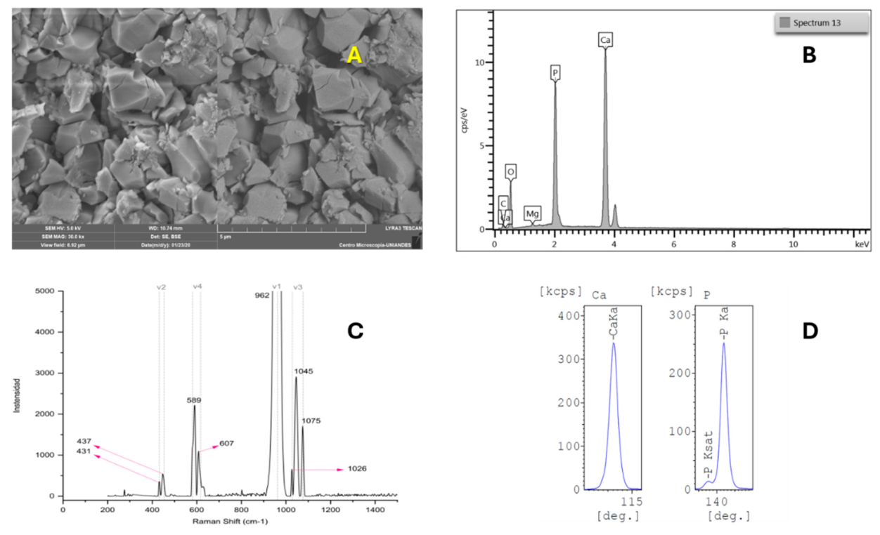
The combined analysis of scanning electron microscopy (SEM), Raman spectroscopy, and energy-dispersive X-ray spectroscopy (EDX) confirmed that the material derived from the eggshells corresponded to crystalline hydroxyapatite (HAp). This biomaterial, which represents the main inorganic component of human bone, served as the primary precursor for the synthesis of the scaffolds developed in this study (Figure 1A–D).
Figure 1.
(A) Scanning electron microscopy (SEM) images showing the polycrystalline surface morphology of sintered HAp, with an average grain size of approximately 1 μm. (B) Raman spectrum of the material obtained after the sintering process. A prominent peak at 961 cm⁻¹ is observed, corresponding to the symmetric stretching vibration mode (ν₁) of the phosphate (PO₄³⁻) group, which is characteristic of apatites [37]. (C) X-ray fluorescence (XRF) spectrum of sintered HAp samples, showing calcium (Ca) and phosphorus (P) contents of 68.15% and 31.85%, respectively, yielding a Ca/P molar ratio of 1.65. (D) Energy-dispersive X-ray spectroscopy (EDX) spectrum used for the elemental analysis of sintered HAp samples.
Figure 1.
(A) Scanning electron microscopy (SEM) images showing the polycrystalline surface morphology of sintered HAp, with an average grain size of approximately 1 μm. (B) Raman spectrum of the material obtained after the sintering process. A prominent peak at 961 cm⁻¹ is observed, corresponding to the symmetric stretching vibration mode (ν₁) of the phosphate (PO₄³⁻) group, which is characteristic of apatites [37]. (C) X-ray fluorescence (XRF) spectrum of sintered HAp samples, showing calcium (Ca) and phosphorus (P) contents of 68.15% and 31.85%, respectively, yielding a Ca/P molar ratio of 1.65. (D) Energy-dispersive X-ray spectroscopy (EDX) spectrum used for the elemental analysis of sintered HAp samples.
The final compositions used for the fabrication of HAp/PLGA/CS scaffolds by freeze-drying and 3D printing are presented in Table 2 and Table 3, respectively.
Figure 2.
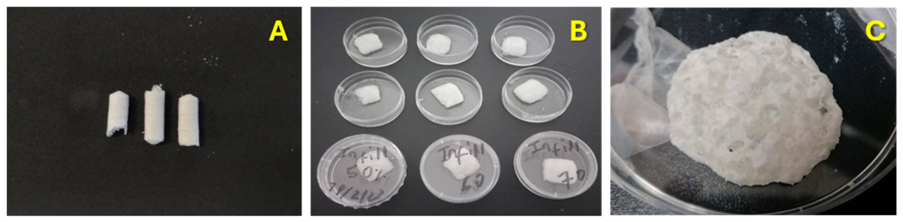
Macrostructure of the two types of scaffolds. (A) Macroscopic image of cylindrical HAp/PLGA/CS scaffolds fabricated using the freeze-drying method. (B) Initial macroscopic view of 3D-printed scaffolds with different infill densities (50%, 60%, and 70%). (C) Final macrostructure of the 3D-printed scaffolds after lyophilization to remove the solvent phase, resulting in enhanced structural integrity and porosity, with morphological features resembling trabecular bone.
Figure 2.
Macrostructure of the two types of scaffolds. (A) Macroscopic image of cylindrical HAp/PLGA/CS scaffolds fabricated using the freeze-drying method. (B) Initial macroscopic view of 3D-printed scaffolds with different infill densities (50%, 60%, and 70%). (C) Final macrostructure of the 3D-printed scaffolds after lyophilization to remove the solvent phase, resulting in enhanced structural integrity and porosity, with morphological features resembling trabecular bone.
3.2. Physical and Structural Characterization of the Two Scaffold Types
3.2.1. Morphology-Derived Porosity
The porosity of HAp/PLGA/CS scaffolds was markedly influenced by the fabrication method and, in the case of 3D printing, by the infill density, as observed in SEM micrographs (Figure 3A–F).
Figure 3.
Scanning electron microscopy (SEM) micrographs of HAp/PLGA/CS scaffolds fabricated by the freeze-drying method (A–C) and by 3D printing (D–F). (A) Large surface pores and smooth regions are observed, features associated with the presence of PLGA within the scaffold matrix. (B) Aggregated hydroxyapatite crystals that form cauliflower-like structures are evident. (C) Well-defined hydroxyapatite (HAp) crystals with characteristic hexahedral morphology are visible on the scaffold surface. (D) SEM micrograph of a 3D-printed scaffold with 50% infill density, showing low surface roughness, smooth regions, and a heterogeneous distribution of small and large pores; in addition to microporosity, larger pores ranging from 180 to 500 μm are observed, indicating a hierarchical porous architecture. (E) SEM micrograph of a 3D-printed scaffold with 60% infill density, exhibiting increased surface roughness, a higher density of relatively large pores, and fewer smooth regions compared with the 50% infill scaffold. (F) SEM micrograph of a 3D-printed scaffold with 70% infill density, showing more uniformly distributed, smaller, and deeper pores, suggesting a more homogeneous porous architecture.
Figure 3.
Scanning electron microscopy (SEM) micrographs of HAp/PLGA/CS scaffolds fabricated by the freeze-drying method (A–C) and by 3D printing (D–F). (A) Large surface pores and smooth regions are observed, features associated with the presence of PLGA within the scaffold matrix. (B) Aggregated hydroxyapatite crystals that form cauliflower-like structures are evident. (C) Well-defined hydroxyapatite (HAp) crystals with characteristic hexahedral morphology are visible on the scaffold surface. (D) SEM micrograph of a 3D-printed scaffold with 50% infill density, showing low surface roughness, smooth regions, and a heterogeneous distribution of small and large pores; in addition to microporosity, larger pores ranging from 180 to 500 μm are observed, indicating a hierarchical porous architecture. (E) SEM micrograph of a 3D-printed scaffold with 60% infill density, exhibiting increased surface roughness, a higher density of relatively large pores, and fewer smooth regions compared with the 50% infill scaffold. (F) SEM micrograph of a 3D-printed scaffold with 70% infill density, showing more uniformly distributed, smaller, and deeper pores, suggesting a more homogeneous porous architecture.
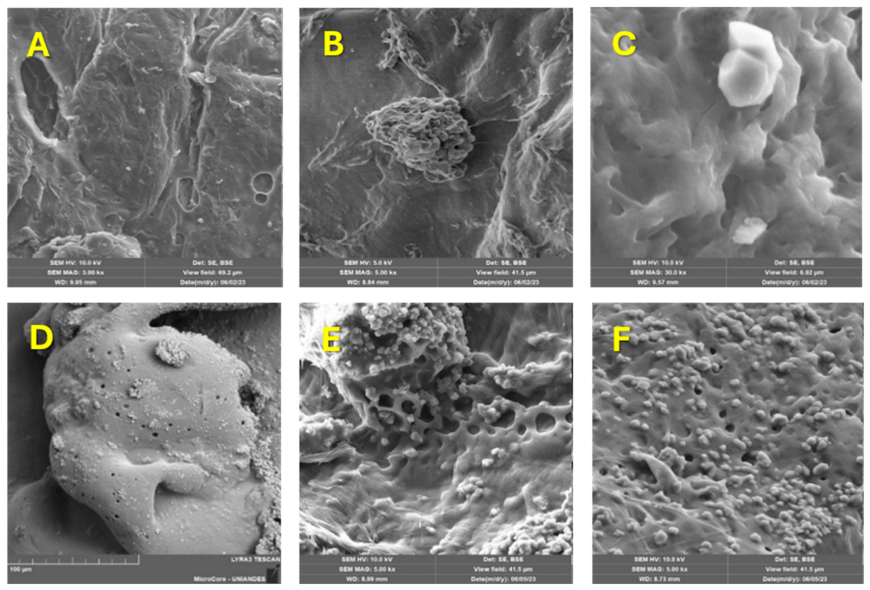
The Freeze-dried scaffolds (Figure 3A–C) exhibited a highly heterogeneous and irregular porous architecture. Large, randomly distributed pores with undefined geometry were embedded within relatively dense regions of the polymer matrix. The pores appeared thick and uneven, and the interconnectivity between the pores was limited. Additionally, the presence of hydroxyapatite aggregates that form cauliflower-like structures and well-defined crystalline domains contributed to localized microporosity but further increased structural heterogeneity. Overall, the freeze-drying process resulted in anisotropic porosity with poor spatial control and limited continuity of the pore network.
In contrast, the 3D-printed scaffolds (Figure 3D–F) showed a more controlled and tunable porous structure, with a clear dependence on the infill density. The 50% infill scaffold (D) showed a relatively smooth surface with low roughness and a heterogeneous distribution of small pores, along with occasional larger voids, suggesting partial pore interconnection but limited uniformity. At 60% infill (Figure 3E), the scaffold exhibited a more open and interconnected porous network, with a higher density of rounded pores and increased surface roughness. The pore structure appeared more continuous, indicating improved pathways for fluid transport and potential cell migration.
The 70% infill scaffold (Figure 3F) demonstrated the most homogeneous pore distribution, characterized by a high density of small, uniformly distributed pores across the surface. These pores appeared more regularly spaced and more clearly interconnected, forming a compact but continuous porous network. This architecture suggests enhanced structural stability and more predictable mechanical behavior, although with reduced macropore size compared to lower infill configurations.
In general, 3D printing enabled precise modulation of pore size, distribution, and interconnectivity, producing scaffolds with a hierarchical porous architecture that more closely resembles trabecular bone. In contrast, freeze-dried scaffolds exhibited random and poorly controlled porosity, which may limit mass transport and uniform tissue ingrowth. These results highlight the critical role of the fabrication technique in tailoring the microstructure of the scaffold for bone tissue engineering applications.
3.2.2. Pore Distribution and Interconnectivity
MATLAB-based image analysis of pore distribution provided detailed insight into the surface morphology of scaffolds fabricated by freeze-drying and 3D printing methods. In addition, depth-map reconstruction and binary image segmentation were used to quantitatively characterize the pore architecture and spatial distribution within the scaffold structure (Figure 4 and Figure 5).
Freeze-Dried Scaffolds
To complement the qualitative SEM observations of the freeze-dried scaffolds (Figure 3A–C), a quantitative image-based porosity analysis was performed using MATLAB (Figure 4). The depth map and binary segmentation (Figure 4A) confirmed that the scaffold surface is predominantly dense, with a limited number of discrete pore regions distributed irregularly throughout the matrix. These findings are consistent with SEM micrographs, which revealed large but poorly interconnected pores embedded within smooth polymer-rich regions.
The segmentation map of the pores in the space (Figure 4B, left) further highlighted the heterogeneous distribution of pores, with isolated clusters rather than a continuous porous network. Quantitative analysis of the pore size distribution (Figure 4B, right) demonstrated that porosity is dominated by micropores, mainly below 1 μm, with a broader range extending to approximately 3.5 μm. The frequency distribution shows a clear inverse relationship between pore size and occurrence, with smaller pores representing the majority of the porous structure.
These results confirm that the freeze-drying process predominantly generates microporous structures with limited interconnectivity, supporting the qualitative interpretation from SEM analysis. The absence of a well-defined hierarchical pore network suggests that, although these scaffolds may support initial cell attachment, their capacity for efficient mass transport, vascularization, and deep cell infiltration may be restricted compared to more architecturally controlled scaffolds fabricated via 3D printing.
3D-printed scaffolds
Figure 5 presents MATLAB-based image analysis of 3D-printed HAp/PLGA/CS scaffolds at different infill densities, including the original SEM micrographs, corresponding depth maps and binary segmentation images.
For the scaffold with 50% infill (Figure 5A), the original SEM image shows a relatively smooth surface containing dispersed pores of varying sizes. The corresponding depth map reveals pronounced variations in surface topography, with localized regions of greater depth associated with larger pores. Binary segmentation highlights a sparse and irregular distribution of pore domains, indicating limited uniformity in pore organization.
In the scaffold with 60% infill (Figure 5B), the SEM image exhibits a more porous and textured surface, with a higher density of visible pores compared to the 50% infill sample. The depth map shows a more homogeneous distribution of depth variations across the surface, suggesting improved structural consistency. Binary segmentation reveals an increased number of pore regions, with a more connected and evenly distributed pattern than that observed in the lower infill scaffold.
For the scaffold with 70% infill (Figure 5C), the SEM image shows a more compact surface with a fine distribution of small pores. The depth map indicates relatively uniform topographical variations, with fewer pronounced deep regions. Binary segmentation reveals a dense distribution of small pore domains that are more regularly spaced across the surface, reflecting a more refined and homogeneous pore network.
The combined qualitative and quantitative analyzes (Figure 3, Figure 4 and Figure 5) demonstrate that scaffold porosity is strongly dependent on the fabrication method and, in the case of 3D printing, on the infill density. The frozen dried scaffolds (Figure 3A–C and 4) exhibited a highly heterogeneous and predominantly microporous structure, characterized by irregular pore geometry, limited interconnectivity, and a pore size distribution mainly below 3.5 μm. MATLAB-based segmentation confirmed that the pore domains were sparse and discontinuous, supporting SEM observations of dense regions interspersed with isolated pores. This type of porosity is typically associated with limited fluid transport and restricted cellular penetration beyond the scaffold surface.
In contrast, 3D-printed scaffolds (Figure 3D–F and 5) showed a progressive refinement of the pore architecture with increasing infill density. The 50% infill scaffolds (Figure 5A) displayed a hierarchical pore system combining macropores (up to ~500 μm) and micropores (1–20 μm), as confirmed by both SEM and depth mapping. Such multiscale porosity is advantageous for bone tissue engineering, as macropores (>100 μm) facilitate vascularization and tissue ingrowth, while micropores enhance protein adsorption and early cell attachment. However, the pore distribution at this infill level remained heterogeneous and less controlled.
At 60% infill (Figure 5B), the pore network became more homogeneous, with a dominant pore size range of 1–3.5 μm and increased pore interconnectivity, as evidenced by the higher fraction of dark regions in binary segmentation images. This configuration suggests improved pathways for nutrient diffusion and cell migration, representing a balance between structural integrity and biological functionality.
The 70% infill scaffolds (Figure 5C) exhibited the most uniform and refined porosity, with a narrow pore size distribution (0.2–1.5 μm) and a predominance of submicron pores. While this highly controlled microporous architecture may enhance surface area for protein adsorption and osteogenic signaling, the reduction in macroporosity could limit deep cell infiltration and vascularization.
In general, these results highlight the trade-off between pore size, interconnectivity, and biological performance. Lower infill densities favor hierarchical porosity and improved mass transport, whereas higher infill densities promote structural uniformity and surface-driven biological interactions. The 3D printing approach, therefore, enables precise modulation of the scaffold architecture, allowing optimization of pore characteristics to balance mechanical stability with osteogenic potential.
3.3. Chemical Analysis of Scaffolds by Energy-Dispersive X-Ray Spectroscopy (EDX)
3.3.1. Freeze-Dried Scaffolds
The elemental composition of the freeze-dried HAp/PLGA/CS scaffolds was evaluated using energy-dispersive X-ray spectroscopy (EDX), as shown in Figure 6. The EDX spectrum (Figure 6B) displays characteristic peaks corresponding to carbon (C), oxygen (O), phosphorus (P) and calcium (Ca), which are the main elements expected in the composite scaffold. Prominent signals associated with carbon and oxygen dominate the spectrum, reflecting the presence of the polymeric components (PLGA and chitosan), while distinct peaks corresponding to calcium and phosphorus confirm the incorporation of hydroxyapatite within the scaffold matrix. Additional minor peaks corresponding to gold (Au) are also observed, originating from the conductive coating applied during the SEM sample preparation.
Quantitative elemental analysis (Figure 6A) indicates that carbon is the most abundant element, with a weight percentage of 60.34% (70.44 at.%), followed by oxygen at 29.11% (25.51 at.%). Calcium and phosphorus are present in lower proportions, with weight percentages of 7.05% (2.47 at.%) and 3.50% (1.59 at.%), respectively. The relative Ca and P contents confirm the presence of a calcium phosphate phase within the scaffold, consistent with the expected composition of hydroxyapatite.
Overall, the EDX results demonstrate a composite structure dominated by the organic polymer matrix, with a homogeneous distribution of inorganic HAp components embedded within it.
3.3.2. 3D-Printed Scaffolds
The elemental composition of the 3D-printed HAp/PLGA/CS scaffolds (60% infill) was analyzed using energy-dispersive X-ray spectroscopy (EDX), as presented in Figure 7. The EDX spectrum (Figure 7B) shows prominent peaks corresponding to oxygen (O), carbon (C), and calcium (Ca), which are consistent with the expected composition of the composite scaffold. Oxygen exhibits the highest intensity peak, followed by carbon, while a distinct calcium peak confirms the presence of the inorganic phase within the scaffold. As observed in the spectrum, minor peaks associated with gold (Au) are also present due to the conductive coating applied during sample preparation.
Quantitative analysis (Figure 7A) reveals that oxygen is the predominant element, with a weight percentage of 57.60% (60.76 at.%), followed by carbon at 21.73% (30.54 at.%). Calcium is present at 20.66% by weight (8.70 at.%), indicating a substantial incorporation of the mineral phase within the scaffold. Notably, phosphorus is not detected in the spectrum, which may be related to its comparatively low concentration or limitations in detection sensitivity under the acquisition conditions.
In general, the EDX results indicate a composition dominated by oxygen and carbon—associated with the polymer matrix and calcium phosphate phases—alongside a significant calcium content, confirming the integration of inorganic components within the 3D-printed scaffold architecture.
A comparison of the EDX results obtained for scaffolds fabricated by freeze-drying (Figure 6) and 3D printing (Figure 7) reveals notable differences in elemental composition and relative phase distribution. The freeze-dried scaffolds (Figure 6) exhibited a composition dominated by carbon (60.34 wt%) and oxygen (29.11 wt%), reflecting the high contribution of the polymeric matrix (PLGA and chitosan). In contrast, calcium (7.05 wt%) and phosphorus (3.50 wt%) were present in relatively low proportions, consistent with a limited exposure or dispersion of the hydroxyapatite phase within the scaffold surface analyzed by EDX.
In comparison, the 3D-printed scaffolds (Figure 7) showed a markedly different elemental profile, characterized by a substantial increase in calcium content (20.66 wt%) and a higher proportion of oxygen (57.60 wt%), accompanied by a significant reduction in carbon content (21.73 wt%). These results suggest a greater relative contribution of the inorganic phase at the analyzed surface, likely due to improved distribution or exposure of hydroxyapatite particles within the 3D-printed architecture.
From an atomic percentage perspective, the freeze-dried scaffold remained dominated by carbon-rich domains (70.44 at.%), whereas the 3D-printed scaffold displayed a more oxygen-rich composition (60.76 at.%) and a higher relative calcium content (8.70 at.% vs. 2.47 at.%).
Overall, these findings indicate that the fabrication method significantly influences the elemental composition of the surface, with freeze-drying producing a polymer-dominated surface and 3D printing promoting increased exposure of the mineral phase. This difference may have important implications for scaffold bioactivity, as higher calcium availability at the surface is typically associated with enhanced osteoconductivity and improved cellular response.
3.4. Biocompatibility Evaluation of HAp/PLGA/Cs Freeze-Dried and 3D-Printed HAp/PLGA/CS Scaffolds
3.4.1. Morphological and Immunophenotypic Characterization of hDPSCs
At day 7 of culture, human dental pulp stem cells (hDPSCs) were observed adhering to the surface of the culture flasks, exhibiting an elongated, fibroblast-like morphology, monolayer organization, and growth characteristics consistent with mesenchymal stem/stromal cells (MSCs). Furthermore, colony-forming unit (CFU) structures were identified as dense cellular clusters composed of spindle-shaped cells radially organized from a central core, confirming the clonogenic potential of the evaluated cell population (Figure 8A).
Immunophenotypic characterization by flow cytometry demonstrated high expression of markers associated with mesenchymal stromal cells. Histograms revealed a clear shift of the cell population toward the positive region, with expression levels of 99.9% for CD105, 99.5% for CD73, and 91.2% for CD90 (Figure 8B). These findings indicate that the hDPSC population maintained a predominantly mesenchymal phenotype under the culture conditions employed.
In contrast, the hematopoietic markers CD45 and CD34 exhibited low expression levels of 0.6% and 3.1%, respectively (Figure 8C). The low expression of these markers, together with the high positivity for CD105, CD73, and CD90, confirms that the cell population displays an immunophenotype consistent with mesenchymal stem/stromal cells (Figure 8D).).
In general, morphological and immunophenotypic analyzes confirm that hDPSCs used in the biocompatibility assays of HAp/PLGA/CS scaffolds retain the defining characteristics of mesenchymal stem/stromal cells.
3.4.2. Evaluation of Cell Viability and Adhesion in HAp/PLGA/CS Scaffolds by Fluorescence Optical Microscopy
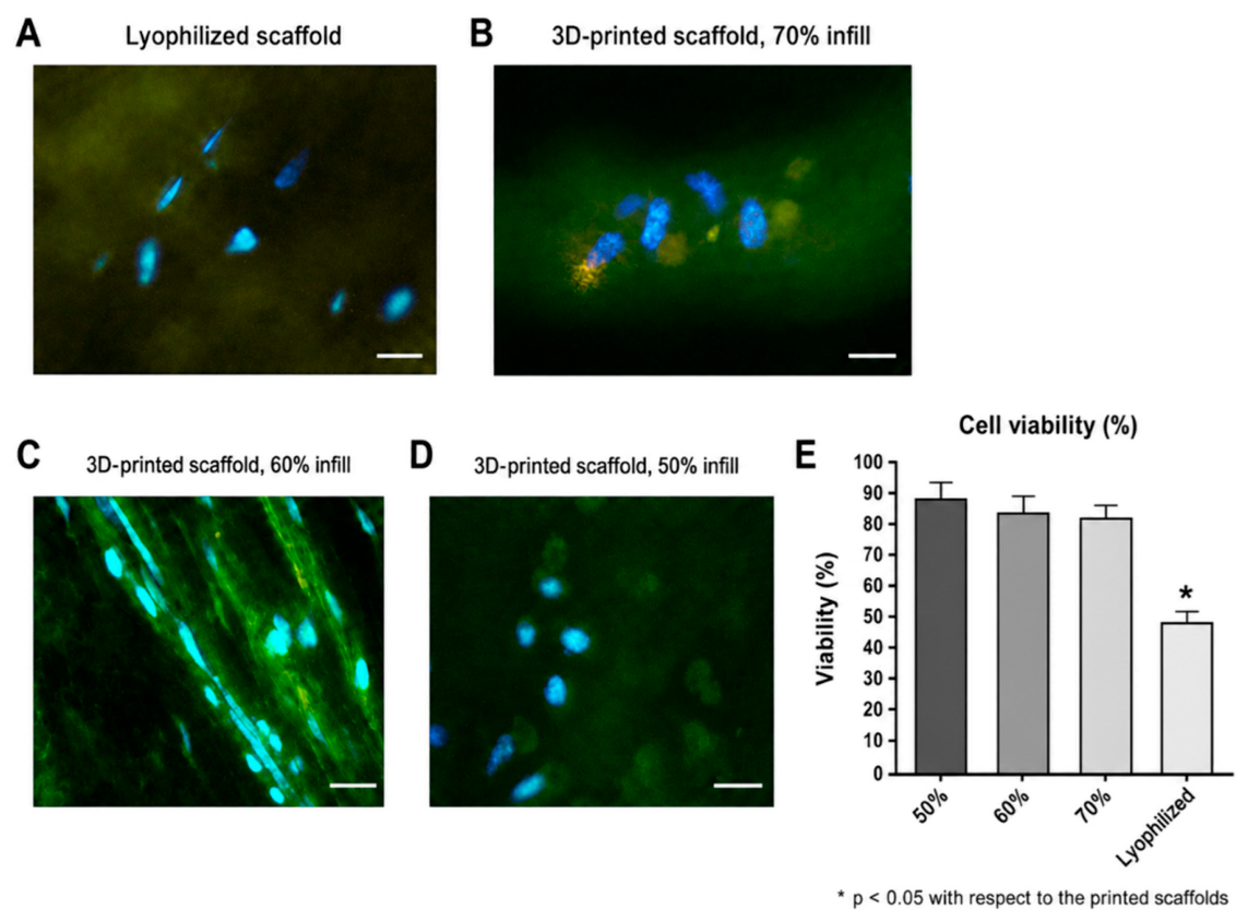
After 7 days of culture, the hDPSCs seeded on HAp/PLGA/CS scaffolds were evaluated using LIVE/DEAD staining and quantitative viability analysis. Fluorescence imaging demonstrated the presence of viable cells adhered to freeze-dried and 3D-printed scaffolds with nominal infill densities of 50%, 60%, and 70% (Figure 9A–D).
In the freeze-dried scaffolds, the fluorescent cells were sparsely distributed on the surface, indicating a lower apparent cell density compared to the 3D-printed scaffolds (Figure 9A). In contrast, the 3D-printed groups exhibited a higher number of adherent viable cells, particularly in 50% and 60% infill scaffolds, where cells were more evenly distributed and closely associated with the scaffold matrix (Figure 9C, 9D). In the 70% infill group, viable cells were also observed; however, their distribution appeared more localized within the analyzed field (Figure 9B).
Quantitative analysis revealed significant differences in cell viability between groups. The 3D-printed scaffolds exhibited the highest viability, reaching approximately 85% in the 50% infill group, followed by the 60% and 70% infill groups. In contrast, the freeze-dried scaffolds showed the lowest viability values, close to 50% (Figure 9E). Statistical analysis confirmed that cell viability in the freeze-dried group was significantly lower than in all 3D-printed scaffold groups (p < 0.05).
Figure 9.
Fluorescence microscopy analysis of cell viability on HAp/PLGA/CS scaffolds fabricated by freeze-drying and 3D printing. (A) Freeze-dried scaffold. (B) 3D-printed scaffold with 70% infill density. (C) 3D-printed scaffold with 60% infill density. (D) 3D-printed scaffold with 50% infill density. (E) Quantitative analysis of cell viability on freeze-dried and 3D-printed scaffolds with different infill densities. The 3D-printed scaffold with 50% infill exhibited significantly higher cell viability, reaching approximately 85%, compared with the freeze-dried scaffold, which showed a viability of approximately 50%.
Figure 9.
Fluorescence microscopy analysis of cell viability on HAp/PLGA/CS scaffolds fabricated by freeze-drying and 3D printing. (A) Freeze-dried scaffold. (B) 3D-printed scaffold with 70% infill density. (C) 3D-printed scaffold with 60% infill density. (D) 3D-printed scaffold with 50% infill density. (E) Quantitative analysis of cell viability on freeze-dried and 3D-printed scaffolds with different infill densities. The 3D-printed scaffold with 50% infill exhibited significantly higher cell viability, reaching approximately 85%, compared with the freeze-dried scaffold, which showed a viability of approximately 50%.
3.4.3. Analysis of Bone-Related Gene Expression: RUNX2, Osterix (OSX), ALP, COL1 and Osteopontin (OPN)
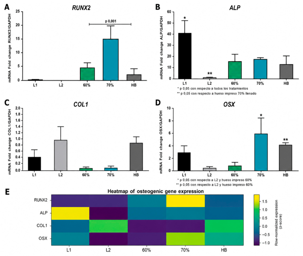
The expression of osteogenic genes in hDPSCs cultured for 7 days on HAp/PLGA/CS scaffolds exhibited different profiles between the experimental groups (Figure 10). RUNX2 expression was predominantly upregulated in the 3D-printed scaffold with 70% infill density (Figure 10A). In contrast, alkaline phosphatase (ALP) expression was highest in the freeze-dried scaffold (L1), followed by the 3D-printed scaffolds with 60% and 70% infill densities, as well as the bovine bone control (Figure 10B).
Collagen type I (COL1) expression was higher in the L2 scaffold and in bovine bone, while lower expression levels were observed in the 3D-printed scaffolds (Figure 10C). Similarly, osterix (OSX) expression was highest in 70% infill scaffold, followed by bovine bone and the L1 scaffold (Figure 10D).
The heatmap analysis summarized the overall gene expression patterns, indicating that each scaffold formulation induced a distinct osteogenic response (Figure 10E). In general, the 3D-printed scaffold with 70% infill density exhibited the most favorable profile for early osteogenic markers, particularly RUNX2 and OSX, suggesting enhanced osteogenic differentiation potential under these conditions.
Figure 10.
Expression of osteogenic differentiation-related genes in hDPSCs cultured on HAp/PLGA/CS scaffolds. Relative gene expression was quantified by RT-qPCR after 7 days of culture on freeze-dried and 3D-printed scaffolds. (A) Relative expression of RUNX2, an early marker associated with osteogenic commitment. (B) Relative expression of alkaline phosphatase (ALP), a marker related to early osteoblastic activity and matrix maturation. (C) Relative expression of collagen type I (COL1), associated with extracellular matrix formation. (D) Relative expression of osterix (OSX), a transcription factor involved in osteoblastic differentiation. (E) Heatmap summarizing osteogenic gene expression between experimental groups, including freeze-dried scaffolds (L1 and L2), 3D-printed scaffolds with 60% and 70% infill densities, and freeze-dried bovine bone (BB) as a reference material. Bar graph data are presented as mean ± standard deviation. The heatmap shows gene-wise normalized expression to facilitate comparison among groups. Statistical significance was defined as p < 0.05, as indicated in each panel.
Figure 10.
Expression of osteogenic differentiation-related genes in hDPSCs cultured on HAp/PLGA/CS scaffolds. Relative gene expression was quantified by RT-qPCR after 7 days of culture on freeze-dried and 3D-printed scaffolds. (A) Relative expression of RUNX2, an early marker associated with osteogenic commitment. (B) Relative expression of alkaline phosphatase (ALP), a marker related to early osteoblastic activity and matrix maturation. (C) Relative expression of collagen type I (COL1), associated with extracellular matrix formation. (D) Relative expression of osterix (OSX), a transcription factor involved in osteoblastic differentiation. (E) Heatmap summarizing osteogenic gene expression between experimental groups, including freeze-dried scaffolds (L1 and L2), 3D-printed scaffolds with 60% and 70% infill densities, and freeze-dried bovine bone (BB) as a reference material. Bar graph data are presented as mean ± standard deviation. The heatmap shows gene-wise normalized expression to facilitate comparison among groups. Statistical significance was defined as p < 0.05, as indicated in each panel.
3.4.4. Evaluation of Mineralized Nodule Formation by Alizarin Red S Staining
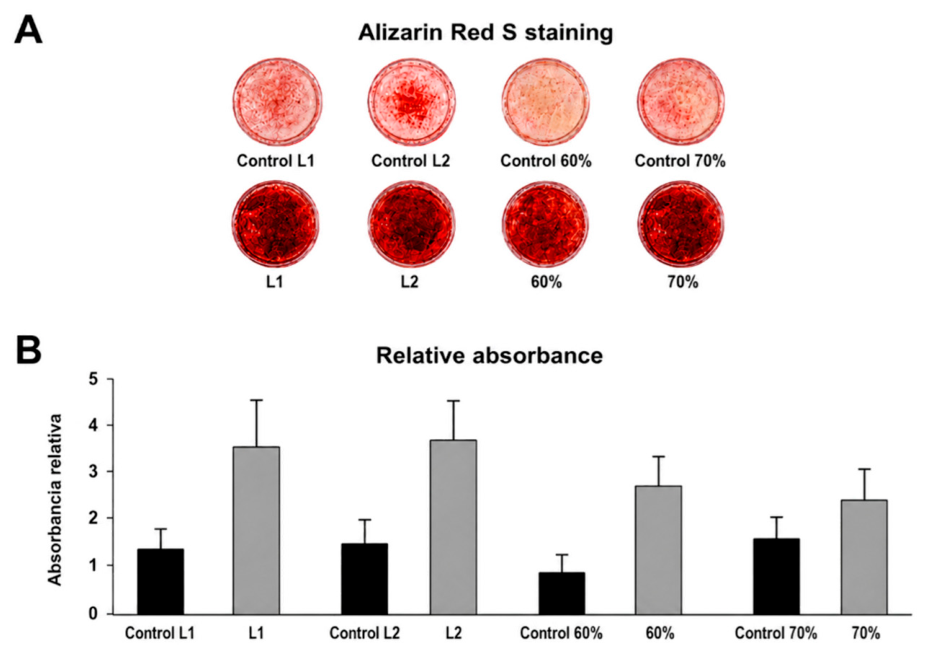
Alizarin Red S staining produced positive signals in both acellular controls and scaffolds cultured with hDPSCs, as expected as a result of the presence of hydroxyapatite within the scaffold composition. However, the experimental groups with cell membranes exhibited more intense staining and higher relative absorbance values compared to their corresponding acellular controls (Figure 11A, 11B).
Figure 11.
Evaluation of mineralized deposits in HAp/PLGA/CS scaffolds by Alizarin Red S staining. (A) Representative images of Alizarin Red S staining for the different experimental groups and corresponding controls, including freeze-dried scaffolds (L1 and L2) and 3D-printed scaffolds with 60% and 70% infill densities, along with their respective acellular controls. (B) Quantitative analysis of Alizarin Red S staining, expressed as relative absorbance for each group. Cell-seeded scaffolds exhibited higher absorbance values compared with their corresponding acellular controls. Data are presented as mean ± standard deviation.
Figure 11.
Evaluation of mineralized deposits in HAp/PLGA/CS scaffolds by Alizarin Red S staining. (A) Representative images of Alizarin Red S staining for the different experimental groups and corresponding controls, including freeze-dried scaffolds (L1 and L2) and 3D-printed scaffolds with 60% and 70% infill densities, along with their respective acellular controls. (B) Quantitative analysis of Alizarin Red S staining, expressed as relative absorbance for each group. Cell-seeded scaffolds exhibited higher absorbance values compared with their corresponding acellular controls. Data are presented as mean ± standard deviation.
3.5. Finite Element Analysis of the Mechanical Properties of HAp/PLGA/CS Scaffolds with and Without Implant Loading
The results of the mechanical simulation obtained using COMSOL Multiphysics reveal a significant variability in the stiffness of the unloaded scaffolds, with values ranging from 4 to 40 MPa. The highest stiffness value corresponded to a scaffold fabricated by the freeze-drying method (40 MPa), suggesting greater resistance to deformation associated with its specific internal architecture. In general, the scaffolds produced by freeze-drying exhibited higher stiffness values compared to those fabricated by 3D printing, although some overlap was observed in the intermediate range. In contrast, 3D-printed scaffolds showed moderate stiffness values between 6 and 19 MPa, consistent with more porous and geometrically controlled structures. Table 4.
Table 5 shows the data used as the basis for predicting the load on these implants and determining whether they meet the mechanical properties required to withstand this load.
Of the 6 scaffolds produced using the freeze-drying method, 5 were selected, corresponding to Models 1 through 5. Of the 4 scaffolds produced using 3D printing, 2 were selected, corresponding to Models 6 and 7. Data on the implants (Brånemark™ system oral implants) and bone were taken from the literature, using previously reported values for mechanical properties such as elastic modulus and density [38,39].
Figures 12A and 12B show the results of the simulation of the von Mises stress distribution along the axis of symmetry when a static compressive load (occlusal) is applied. Models 4 and 7 were selected, as they have the highest modulus of elasticity values for scaffolds manufactured by the freeze-drying method and 3D printing, respectively. In both cases, it can be observed that in most of the cylinder (green zone for Model 4 and magenta zone for Model 7), the stress stabilizes uniformly. The highest stress concentration occurs at the base of the cylinder (from z = 0 mm to approximately z = 3 mm). The material exhibits elastic behavior according to Hooke's law. The highest stress values occur in the red region, exceeding 9 MPa for Model 4 and approximately 3.5 MPa for Model 7. This stress concentration could lead to a fracture or collapse precisely at the base but not in the body of the cylinder.
Figure 12.
Images from the MEF simulation of the HAp/CS/PLGA scaffolds. The models are shown on a color scale that corresponds to the stress distribution along the cylinder’s axis, where red indicates the region of maximum deformation, which is also observed in the z-direction. The implant used is a titanium implant with 60% porosity (Branemark System). (A) Scaffold fabricated using the freeze-drying method (model 4). (B) Scaffold fabricated using the 3D printing method (model 7). (C) Scaffold model 7 with a titanium implant.
Figure 12.
Images from the MEF simulation of the HAp/CS/PLGA scaffolds. The models are shown on a color scale that corresponds to the stress distribution along the cylinder’s axis, where red indicates the region of maximum deformation, which is also observed in the z-direction. The implant used is a titanium implant with 60% porosity (Branemark System). (A) Scaffold fabricated using the freeze-drying method (model 4). (B) Scaffold fabricated using the 3D printing method (model 7). (C) Scaffold model 7 with a titanium implant.
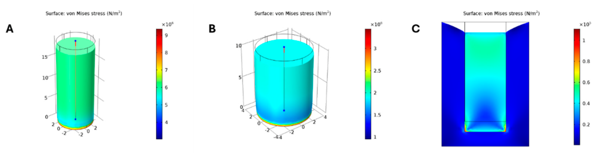
Figure 12C shows a simplified two-dimensional simulation of a model 7 scaffold with a smooth titanium implant that has 60% porosity (Branemark System). A force is applied to the implant in the -z direction, and the implant, in turn, exerts a force on the scaffold. A phenomenon of implant penetration into the scaffold is thus observed. The modulus of elasticity of the implant is 500 times greater than that of the scaffold. Due to the large difference in the moduli, no “load” transfer from the implant to the scaffold is observed; this can be seen from the uniform blue color in the matrix. This phenomenon is known as “stress shielding.” Stress concentration occurs at the base of the implant and particularly at its edges; this phenomenon can lead to plastic deformation and likely to a fracture of the scaffold. On the other hand, at the surface of the matrix (z = 10 mm), distortion occurs, meaning that the walls adjacent to the implant pull the scaffold downward as a shear stress, deforming its geometry. The smooth metal implant transmits the load primarily through the lower edges at the base, resulting in potential local damage due to this stress concentration.
To achieve better load transfer from the implant to the scaffold, the modulus of elasticity must be increased to values close to those of the implant. Furthermore, the implant should not have smooth walls but rather a grooved surface, like a screw. This ensures better load transfer and prevents localized stress concentration.
4. Discussion
The treatment of bone defects remains a significant clinical challenge. Despite advances in tissue engineering, no definitive solution has yet been achieved [40]. In this context, research has increasingly focused on the development of biocomposite scaffolds capable of promoting cell proliferation, differentiation, and subsequent bone tissue formation [41,42,43,44]. Among the most promising strategies are the freeze-drying method and 3D printing, which stand out for their ability to produce structures with adapted physical, mechanical and morphological properties suitable for bone regeneration [28,41,42,43,44].
In the present study, HAp/PLGA/CS scaffolds were fabricated using freeze-drying and 3D printing techniques. Their physicochemical and mechanical properties were characterized and their biocompatibility was evaluated using hDPSCs. The selection of polymeric components was motivated by the need to overcome the intrinsic limitations of hydroxyapatite (HAp), which, although highly biocompatible and osteoconductive, exhibits poor mechanical performance when used alone [43]. Incorporation of chitosan (CS) and poly(lactic-coglycolic acid) (PLGA) improves structural stability and facilitates the development of composite systems that more closely mimic the composition and function of native bone tissue [16,17,18,19,20,41,42,43,44]. Additionally, finite element analysis (FEA) was employed to predict scaffold behavior under implant-related loading conditions, aiming to evaluate their potential for reducing oral rehabilitation times through the future implementation of simultaneous scaffold–implant placement [30,38].
A distinctive aspect of this study was the use of hydroxyapatite (HAp) derived from eggshells, an abundant agro-industrial waste byproduct, obtained by a wet-chemical synthesis method [31]. Elemental analysis revealed a Ca/P ratio of 1.65, which is markedly close to the stoichiometric ratio of pure hydroxyapatite (1.67). This calcium phosphate phase was further confirmed by X-ray fluorescence (XRF), energy-dispersive X-ray spectroscopy (EDX), and Raman spectroscopy analyzes (A–D). Despite minor deviations, the obtained material exhibited characteristic physicochemical features of crystalline hydroxyapatite compounds, which confirms the effectiveness of the synthesis method. These findings support the use of eggshells as a viable, low-cost and sustainable alternative source to produce HAp-like biomaterials, with crystallographic properties comparable to those reported in previous studies [45,46].
However, during scaffold fabrication, HAp exhibited a tendency to aggregate within the polymeric matrix, leading to a heterogeneous distribution. This behavior has also been described for inorganic calcium phosphate particles dispersed in polymeric matrices, where particle agglomeration may compromise homogeneity and affect the scaffold architecture. To mitigate this effect, the relative proportion of HAp was reduced, while the concentrations of CS and PLGA were increased in the final formulations (Table 2 and Table 3). This adjustment proved to be critical for improving material homogeneity and achieving a more controlled porous architecture.
The resulting scaffolds exhibited distinct porosity characteristics depending on the fabrication method. Quantitative image analysis (Figure 4 and Figure 5) revealed that the freeze-dried scaffolds were predominantly microporous, with pore sizes mainly below 3.5 μm, limited interconnectivity, and a heterogeneous spatial distribution. In contrast, 3D-printed scaffolds showed a hierarchical and tunable pore architecture, with the pore size and distribution strongly influenced by the infill density. In particular, 50% infill scaffolds exhibited a multiscale pore system, including macropores (up to ~500 μm) alongside micro- and submicron pores, while increasing infill density (60% and 70%) resulted in a more homogeneous and refined microporous network (Figure 3 and Figure 5).
These observations are consistent with the known influence of fabrication techniques on scaffold architecture. The freeze-drying process generates porosity through solvent sublimation, leading to irregular and poorly controlled pore networks, while 3D printing enables precise control over pore size, geometry, and interconnectivity [28,41,42,43,44]. The discrepancy between the large pores observed in the SEM micrographs and the pore size distributions obtained through image processing suggests that some macropores were segmented into smaller domains, resulting in an underestimation of their effective size. Nevertheless, both types of scaffolds exhibited hierarchical porosity spanning multiple length scales.
From a biological perspective, the presence of multiscale porosity is highly relevant. Macropores (>100 μm) are essential for vascularization and tissue growth, while micropores and submicrometer features enhance protein adsorption, cell attachment, and osteogenic signaling [47,48,49]. Consequently, the hierarchical pore architecture observed in the 3D-printed scaffolds is expected to provide a more favorable microenvironment for bone regeneration. In contrast, the predominantly microporous structure of freeze-dried scaffolds can limit mass transport and restrict deep cell infiltration, particularly within the inner regions of the scaffold [47,48,49,50,51,52].
The compositional analysis further supported these structural differences. EDX results (Figure 6 and Figure 7) indicated that the freeze-dried scaffolds were dominated by carbon-rich domains, reflecting a higher contribution of the polymer matrix. In contrast, 3D-printed scaffolds exhibited a significantly higher calcium content and reduced carbon proportion, suggesting greater exposure or a more uniform distribution of the inorganic phase at the surface. This enhanced mineral availability may play a key role in promoting osteoconductivity and supporting cellular responses, since calcium-rich bioactive surfaces have been associated with protein adsorption, osteogenic signaling, mineral deposition, and osteoblastic differentiation [53,54,55,56].
The biological results are consistent with these structural and compositional observations. Quantitative analysis demonstrated significantly higher cell viability in 3D-printed scaffolds compared with freeze-dried scaffolds (p < 0.05), with the 50% infill group reaching approximately 85% viability. This result is likely associated with the presence of larger pores and improved interconnectivity, which facilitate nutrient diffusion, oxygen transport, metabolic waste removal, and cellular proliferation within three-dimensional biomaterials [47,48,49,50,51,52].
Interestingly, the scaffold exhibiting the highest cell viability was not the one with the strongest osteogenic response. While the 50% infill scaffold provides a more permissive environment for cell survival, the 70% infill scaffold demonstrated enhanced expression of early osteogenic markers (RUNX2 and OSX). This finding highlights a critical trade-off between porosity and biological function, where larger pores favor cell viability and transport phenomena, whereas more compact and refined architectures may promote cell–material interactions and osteogenic differentiation [47,48,49,50,51,52].
These results indicate that scaffold architecture influences not only cell survival, but also lineage commitment, highlighting that favorable conditions for proliferation do not necessarily coincide with those that optimize osteogenic differentiation. In contrast, the freeze-dried scaffolds exhibited the lowest cell viability, with values close to 50% (E). The observed differences in cell viability and osteogenic response are likely associated with the distinct microstructural features generated by each fabrication method. As discussed above, the 3D-printed scaffolds exhibited a hierarchical and highly interconnected pore network, providing a more favorable microenvironment for cell survival, migration, and biological function [53,54,55,56,57,58,59,60,61].
The additive manufacturing process enables precise control over the scaffold architecture, allowing modulation of pore size, interconnectivity, and permeability. These parameters directly influence mass transport phenomena, including nutrient diffusion, oxygen delivery, and metabolic waste removal, which are critical to maintaining cell viability in three-dimensional biomaterials [50,51]. Furthermore, a well-interconnected porous network facilitates cell migration and homogeneous distribution throughout the scaffold, promoting effective colonization and supporting tissue regeneration processes [51,52].
In contrast, although the freeze-dried scaffolds exhibited a relatively rough surface that may enhance initial cell attachment, their lower effective porosity and limited pore interconnectivity likely restrict nutrient and oxygen transport to the scaffold interior. This limitation is consistent with the reduced cell viability observed in this group. Previous studies have demonstrated that insufficient pore interconnectivity significantly impairs nutrient diffusion and metabolic waste removal, thereby compromising cell proliferation, survival, and colonization within the inner regions of the scaffold [52]. These findings help explain why 3D-printed scaffolds, particularly those with optimized infill architectures, exhibited superior biological performance compared to their freeze-dried counterparts.
Consistent with the Alizarin Red S staining results, which revealed increased mineralization-related activity in the 60% and especially the 70% infill scaffolds, gene expression analysis further demonstrated enhanced osteogenic commitment in these groups. All scaffolds supported the activation of osteogenic-related genes; however, the 3D-printed scaffold with 70% infill density exhibited the most favorable expression profile, with higher levels of RUNX2, OSX, ALP, and OPN compared with the other scaffold formulations. In contrast, lower expression levels of these markers were observed in freeze-dried scaffolds and in 3D-printed scaffolds with lower infill densities.
The elevated expression of RUNX2 and OSX in the 70% infill scaffold indicates enhanced commitment of hDPSCs toward the osteoblastic lineage, as these transcription factors play central roles in the initiation and progression of osteogenic differentiation [53,57,58,59,60,61]. Similarly, the expression of ALP across all groups confirms the onset of osteoblastic maturation and early mineralization processes, while the relatively low expression of COL1 suggests that extracellular matrix deposition remains at an early stage after 7 days of culture [53,54,55,56,57,58].
The increased expression of osteopontin (OPN), particularly in the 70% infill scaffold, further supports the activation of early mineralization-related pathways and cell–matrix interactions. Previous studies have shown that bioactive scaffolds can promote osteogenesis from early stages by enhancing calcium deposition, protein adsorption, and osteoblastic differentiation [53,54,55,56]. In this context, the compositional differences observed by EDX analysis (Figure 6 and Figure 7), particularly the higher calcium availability in 3D-printed scaffolds, may contribute to the enhanced osteogenic response observed in these groups [59,60,61].
Taken together, these findings suggest that the structural and compositional characteristics of the 70% infill scaffold provide a more favorable microenvironment for osteogenic differentiation. The combination of a refined microporous network, adequate interconnectivity, and increased exposure of mineral phases may enhance cell–material interactions and mechanotransduction signaling, thereby stimulating osteogenic gene expression [53,57,58,59,60,61]. While lower infill densities favor cell viability through improved mass transport, higher infill densities appear to promote osteogenic commitment. This highlights a critical structure–function relationship, in which scaffold architecture must be carefully optimized to balance cell survival and differentiation. Overall, the 70% infill scaffold emerges as the most promising formulation for supporting early osteogenic commitment and bone tissue regeneration.
In addition to promoting favorable cellular and osteogenic responses, an ideal scaffold must exhibit a degradation profile compatible with the rate of new tissue formation. Consequently, scaffold degradation was evaluated in the present study. Previous reports indicate that the optimal onset of degradation should occur between 4 and 6 weeks, corresponding to the period preceding lamellar bone deposition. This temporal synchronization is essential to ensure that the scaffold provides adequate structural support during the early stages of tissue regeneration while being progressively replaced by newly formed bone. In contrast, excessively rapid degradation may compromise mechanical stability, whereas prolonged persistence may hinder tissue ingrowth and integration [48].
Within this framework, the degradation behavior observed for the HAp/PLGA/CS scaffolds was consistent with the requirements for early bone regeneration. Freeze-dried scaffolds initiated degradation approximately 4 weeks after cell seeding, while 3D-printed scaffolds exhibited earlier onset, around 3 weeks. Importantly, structural remnants were still detectable between weeks 4 and 6 (A, 11B), indicating that both types of scaffold retained sufficient integrity to support cellular activity and early bone formation during this critical phase. This finding is particularly relevant in light of the enhanced osteogenic response observed in 3D-printed scaffolds, suggesting that their degradation kinetics provide a favorable balance between temporary mechanical support and progressive tissue replacement. In general, both fabrication methods yielded degradation profiles compatible with bone regeneration, although 3D-printed scaffolds combined earlier degradation with sustained structural stability.
Although biological results highlight the regenerative potential of these scaffolds, their clinical applicability also depends on their ability to withstand physiological loading conditions. In this context, finite element analysis (FEA) performed using COMSOL Multiphysics® provided valuable information on the biomechanical environment at the implant–scaffold interface [30,38]. Specifically, simulations were conducted using a 60% porous titanium implant (Brånemark™ System), enabling rapid and cost-effective prediction of the composite system behavior under functional loading conditions. When considered alongside the biological findings, these simulations contribute to a more comprehensive evaluation of scaffold performance by linking osteogenic potential with mechanical functionality.
The results indicated that Models 4 and 7 exhibited compressive strengths lower than those typically reported for cancellous bone, suggesting that these scaffolds are not intended to fully replace the structural role of bone tissue. Instead, they should be interpreted as bioactive matrices designed to support cell colonization, mechanotransduction, and osteogenesis during the early stages of regeneration. Despite their relatively low stiffness, the HAp/PLGA/CS system retains significant therapeutic potential by providing osteoconductive and osteoinductive signals that favor bone tissue formation [43,53,59,60,61].
FEA simulations further revealed that the mismatch between the elastic modulus of the titanium implant and that of the scaffold generated a non-uniform stress distribution at the interface. This mismatch may compromise primary stability and lead to localized implant subsidence under loading conditions. These findings are consistent with previous reports, such as those of Pérez et al. (2015) [38], which demonstrated that implants with controlled porosity can improve load-transfer behavior and reduce the effects of stress shielding.
Together, these results underscore the importance of achieving an optimal balance between porosity and mechanical strength. As demonstrated throughout this study, the scaffold architecture influences not only cell viability, osteogenic differentiation, and tissue regeneration, but also mechanical performance and long-term functionality of the implant–scaffold system. Although the compressive properties measured experimentally fall within the lower range reported for porous bone, FEA simulations indicate that certain scaffold configurations may still be susceptible to excessive deformation under implant-related loading conditions. Therefore, further optimization of the scaffold design is required to enhance mechanical stability while preserving the favorable biological properties associated with hierarchical porosity and mineral phase distribution.
5. Conclusions
HAp/PLGA/CS scaffolds fabricated using both freeze-drying and 3D printing techniques demonstrated suitable biocompatibility with hDPSCs and supported early osteogenic responses under in vitro conditions. In particular, the 3D printing approach enabled precise control over scaffold architecture, resulting in hierarchical and interconnected porous networks that enhanced both cell viability and osteogenic differentiation.
Among the designs evaluated, the 50% infill scaffold exhibited the highest cell viability, whereas the 70% infill scaffold presented the most favorable osteogenic profile, as evidenced by the increased expression of key osteogenic markers (RUNX2, OSX, ALP, and OPN) and enhanced mineralization-related activity. These findings highlight the critical role of scaffold architecture in modulating cellular behavior, demonstrating a clear structure–function relationship in which porosity influences both cell survival and lineage commitment.
In addition, the degradation profiles of both fabrication methods were consistent with the requirements for early bone regeneration, maintaining sufficient structural integrity during the initial stages of tissue formation. However, the interpretation of Alizarin Red S staining results should be considered with caution due to the intrinsic mineral composition of hydroxyapatite-based scaffolds.
Finite element analysis also indicated that current scaffold formulations require mechanical optimization to improve load transfer and reduce deformation at the implant–scaffold interface. These results emphasize that, beyond biological performance, mechanical compatibility remains a key factor for successful clinical translation.
In general, the combined structural, compositional, biological, and biomechanical findings support the potential of HAp/PLGA/CS scaffolds as bioactive platforms for bone tissue engineering. In particular, 3D-printed scaffolds offer significant advantages in architectural control and osteogenic performance. Nevertheless, further optimization of mechanical properties, along with comprehensive in vivo validation, will be necessary to fully establish their applicability in clinical settings.
Author Contributions
Conceptualization, S.J.G.-P., S.J.P.-L., H.A.M.-P., H.R.-H, .and LG.S.-C.; methodology, S.J.G.-P., S.J.P.-L., J.M.P.-B., H.A.M.-P., H.R.-H., and LG.S.-C.; software, J.M.P.-B., H.A.M.-P., H.R.-H.; validation, S.J.G.-P., H.A.M.-P., H.R.-H, .and LG.S.-C.; formal analysis, J.M.P.-B., S.J.G.-P., S.J.P.-L., H.A.M.-P., H.R.-H, .and LG.S.-C.; investigation, J.M.P.-B., M.B.S.-V., S.J.G.-P., S.J.P.-L., H.A.M.-P., H.R.-H, .and LG.S.-C.; resources, S.J.G.-P., S.J.P.-L.; data curation, J.M.P.-B., S.J.G.-P., H.A.M.-P., H.R.-H, .and LG.S.-C.; writing—original draft preparation, J.M.P.-B.; S.J.G.-P., and LG.S.-C..; writing—review and editing, J.M.P.-B., S.J.G.-P., S.J.P.-L., H.A.M.-P., H.R.-H, .and LG.S.-C.; visualization, J.M.P.-B., S.J.G.-P., H.A.M.-P., H.R.-H, .and LG.S.-C.; supervision, S.J.G.-P., H.A.M.-P., H.R.-H, .and LG.S.-C.; project administration, S.J.G.-P., and LG.S.-C. funding acquisition, S.J.G.-P., S.J.P.-L., and LG.S.-C.. All authors have read and agreed to the published version of the manuscript.
Funding
This work was carried out with resources remaining from projects 8576, 6387, 3263 funded by the Academic Vice-Rectory and the Vice-Rectory for Research of the Pontificia Universidad Javeriana.
Institutional Review Board Statement
Not applicable. The study used commercially available human dental pulp stem cells (Poietics™ hDPSCs, Lonza, Walkersville, MD, USA), and no human participants, human tissue collection, or identifiable human data were directly involved in this study.
Informed Consent Statement
Not applicable. Commercially available human dental pulp stem cells were used and no new human samples or identifiable human data were collected.
Data Availability Statement
Data supporting the findings of this study are available from the corresponding author on a reasonable request. Raw and processed datasets include SEM image analysis, elemental composition data, mechanical testing results, RT-qPCR Ct values, Alizarin Red absorbance data, and finite element simulation outputs. The COMSOL model files and image analysis scripts can be made available upon request, subject to institutional data-sharing policies.
Acknowledgments
The authors thank the Dentistry Research Center (Centro de Investigaciones Odontológicas—CIO) of the Pontificia Universidad Javeriana.
Conflicts of Interest
The authors declare that they have no conflicts of interest.
Abbreviations
The following abbreviations are used in this manuscript:
| HAp | Hydroxyapatite |
| PLGA | Poly(lactic-co-glycolic acid) |
| CS | Chitosan |
| hDPSCs | Human dental pulp stem cells |
| SEM | Scanning electron microscopy |
| EDX | Energy-dispersive X-ray spectroscopy |
| XRF | X-ray fluorescence |
| RT-qPCR | Reverse transcription quantitative polymerase chain reaction |
| ALP | Alkaline phosphatase |
| RUNX2 | Runt-related transcription factor 2 |
| OSX | Osterix |
| COL1 | Type I collagen |
| OP | Osteopontin |
| FEA | Finite element analysis |
| FEM | Finite element method |
References
- WHO. Global oral Health Status Report: Towards Universal Health Coverage for Oral Health by 2030; World Health Organization: Geneva, Switzerland, 18 November 2022; p. 100. [Google Scholar]
- Jain, N.; Dutt, U.; Radenkov, I.; Jain, S. WHO's global oral health status report 2022: Actions, discussion and implementation. Oral Dis. 2024, 30, 73–79. [Google Scholar] [CrossRef] [PubMed]
- Rosing, C.K.; Randall, C.; Giacaman, R.A. Editorial: Dental caries and periodontal diseases as non-communicable chronic diseases. Front Oral Health 2022, 3, 1113029. [Google Scholar] [CrossRef] [PubMed]
- Yen, A.-H.; Yelick, P.C. Dental Tissue Regeneration – A Mini-Review. Gerontology 2010, 57, 85–94. [Google Scholar] [CrossRef] [PubMed]
- Walls, A.W.; Steele, J.G. The relationship between oral health and nutrition in older people. Mech. Ageing Dev. 2004, 125, 853–857. [Google Scholar] [CrossRef] [PubMed]
- Walls, A.W.; Steele, J.G.; Sheiham, A.; Marcenes, W.; Frsa, P. Oral Health and Nutrition in Older People. J. Public Health Dent. 2000, 60, 304–307. [Google Scholar] [CrossRef] [PubMed]
- Elgali, I.; Omar, O.; Dahlin, C.; Thomsen, P. Guided bone regeneration: Materials and biological mechanisms revisited. Eur. J. Oral Sci. 2017, 125, 315–337. [Google Scholar] [CrossRef] [PubMed]
- García-Gareta, E.; Coathup, M.J.; Blunn, G.W. Osteoinduction of bone grafting materials for bone repair and regeneration. Bone 2015, 81, 112–121. [Google Scholar] [CrossRef] [PubMed]
- Abdulghani, S.; Mitchell, G.R. Biomaterials for In Situ Tissue Regeneration: A Review. Biomolecules 2019, 9, 750. [Google Scholar] [CrossRef] [PubMed]
- O'Brien, F.J. Biomaterials & scaffolds for tissue engineering. Mater. Today 2011, 14, 88–95. [Google Scholar] [CrossRef]
- Chu, T.M.; Orton, D.G.; Hollister, S.J.; Feinberg, S.E.; Halloran, J.W. Mechanical and in vivo performance of hydroxyapatite implants with controlled architectures. Biomaterials 2002, 23, 1283–1293. [Google Scholar] [CrossRef] [PubMed]
- Boga, J.C.; Miguel, S.P.; de Melo-Diogo, D.; Mendonça, A.G.; Louro, R.O.; Correia, I.J. In vitro characterization of 3D printed scaffolds aimed at bone tissue regeneration. Colloids Surf. B Biointerfaces 2018, 165, 207–218. [Google Scholar] [CrossRef] [PubMed]
- Bouet, G.; Marchat, D.; Cruel, M.; Malaval, L.; Vico, L. In vitro three-dimensional bone tissue models: From cells to controlled and dynamic environment. Tissue Eng. Part B Rev. 2015, 21, 133–156. [Google Scholar] [CrossRef] [PubMed]
- Annabi, N.; Tamayol, A.; Uquillas, J.A.; Akbari, M.; Bertassoni, L.E.; Cha, C.; Camci-Unal, G.; Dokmeci, M.R.; Peppas, N.A.; Khademhosseini, A. 25th anniversary article: Rational design and applications of hydrogels in regenerative medicine. Adv. Mater. 2014, 26, 85–123. [Google Scholar] [CrossRef] [PubMed]
- Rao, S.H.; Harini, B.; Shadamarshan, R.P.K.; Balagangadharan, K.; Selvamurugan, N. Natural and synthetic polymers/bioceramics/bioactive compounds-mediated cell signalling in bone tissue engineering. Int. J. Biol. Macromol. 2018, 110, 88–96. [Google Scholar] [CrossRef] [PubMed]
- Kim, S.S.; Park, M.S.; Gwak, S.J.; Choi, C.Y.; Kim, B.S. Accelerated bonelike apatite growth on porous polymer/ceramic composite scaffolds in vitro. Tissue Eng. 2006, 12, 2997–3006. [Google Scholar] [CrossRef] [PubMed]
- Wei, G.; Ma, P.X. Structure and properties of nano-hydroxyapatite/polymer composite scaffolds for bone tissue engineering. Biomaterials 2004, 25, 4749–4757. [Google Scholar] [CrossRef] [PubMed]
- Gutiérrez-Prieto, S.J.; Fonseca, L.F.; Sequeda-Castañeda, L.G.; Díaz, K.J.; Castañeda, L.Y.; Leyva-Rojas, J.A.; Salcedo-Reyes, J.C.; Acosta, A.P. Elaboration and Biocompatibility of an Eggshell-Derived Hydroxyapatite Material Modified with Si/PLGA for Bone Regeneration in Dentistry. Int. J. Dent. 2019, 2019, 5949232. [Google Scholar] [CrossRef] [PubMed]
- Gutiérrez-Prieto, S.J.; Perdomo-Lara, S.J.; Diaz-Peraza, J.M.; Sequeda-Castañeda, L.G. Analysis of In Vitro Osteoblast Culture on Scaffolds for Future Bone Regeneration Purposes in Dentistry. Adv. Pharmacol. Pharm. Sci. 2019, 2019, 5420752. [Google Scholar] [CrossRef] [PubMed]
- Kim, H.W.; Kim, H.E.; Salih, V. Stimulation of osteoblast responses to biomimetic nanocomposites of gelatin-hydroxyapatite for tissue engineering scaffolds. Biomaterials 2005, 26, 5221–5230. [Google Scholar] [CrossRef] [PubMed]
- Zhang, Y.; Ni, M.; Zhang, M.; Ratner, B. Calcium phosphate-chitosan composite scaffolds for bone tissue engineering. Tissue Eng. 2003, 9, 337–345. [Google Scholar] [CrossRef] [PubMed]
- Chesnutt, B.M.; Yuan, Y.; Buddington, K.; Haggard, W.O.; Bumgardner, J.D. Composite chitosan/nano-hydroxyapatite scaffolds induce osteocalcin production by osteoblasts in vitro and support bone formation in vivo. Tissue Eng. Part A 2009, 15, 2571–2579. [Google Scholar] [CrossRef] [PubMed]
- Rodrigues, C.V.; Serricella, P.; Linhares, A.B.; Guerdes, R.M.; Borojevic, R.; Rossi, M.A.; Duarte, M.E.; Farina, M. Characterization of a bovine collagen-hydroxyapatite composite scaffold for bone tissue engineering. Biomaterials 2003, 24, 4987–4997. [Google Scholar] [CrossRef] [PubMed]
- Raman, H. An Organic Bovine Hydroxyapatite-PLGA Composites for Bone Tissue Engineering Master Thesis. University of Kentucky Lexington, Kentucky, 2005. [Google Scholar]
- Cinici, B.; Yaba, S.; Kurt, M.; Yalcin, H.C.; Duta, L.; Gunduz, O. Fabrication Strategies for Bioceramic Scaffolds in Bone Tissue Engineering with Generative Design Applications. Biomimetics 2024, 9, 409. [Google Scholar] [CrossRef] [PubMed]
- Potdar, P.D.; Jethmalani, Y.D. Human dental pulp stem cells: Applications in future regenerative medicine. World J. Stem Cells 2015, 7, 839–851. [Google Scholar] [CrossRef] [PubMed]
- Soto-Navarrete, E.; Vargas-Ulloa, L.E.; Oropeza-Murilo, M.P. Pluripotent Cells from Human Dental Pulp The Future of Regenerative Dentistry. Odontol. Act. 2015, 11, 4–14. [Google Scholar]
- Egusa, H.; Sonoyama, W.; Nishimura, M.; Atsuta, I.; Akiyama, K. Stem cells in dentistry – Part I: Stem cell sources. J. Prosthodont. Res. 2012, 56, 151–165. [Google Scholar] [CrossRef] [PubMed]
- Friberg, B.; Dahlin, C.; Widmark, G.; Ostman, P.O.; Billström, C. One-year results of a prospective multicenter study on Brånemark System implants with a TiUnite surface. Clin. Implant Dent. Relat. Res. 2005, 7 Suppl 1, S70–S75. [Google Scholar] [CrossRef] [PubMed]
- Zienkiewicz, O.C.; Taylor, R.L.; Govindjee, S. The Finite Element Method: Its Basis and Fundamentals; Butterworth-Heinemann, 2024. [Google Scholar]
- Sequeda, L.G.; Díaz, J.M.; Gutiérrez, S.J.; Perdomo, S.J.; Gómez, O.L. Synthetic hydroxyapatite obtaining using three different methods and characterization to use it as bone substitute. Rev. Colomb. De Cienc. Quím.-Farm. 2012, 41, 50–66. [Google Scholar]
- Wang, F.; Zhang, Y.C.; Zhou, H.; Guo, Y.C.; Su, X.X. Evaluation of in vitro and in vivo osteogenic differentiation of nano-hydroxyapatite/chitosan/poly(lactide-co-glycolide) scaffolds with human umbilical cord mesenchymal stem cells. J. BioMed Mater. Res. A 2014, 102, 760–768. [Google Scholar] [CrossRef] [PubMed]
- Li, Y.; Zhang, Z.; Zhang, Z. Porous Chitosan/Nano-Hydroxyapatite Composite Scaffolds Incorporating Simvastatin-Loaded PLGA Microspheres for Bone Repair. Cells Tissues Organs 2018, 205, 20–31. [Google Scholar] [CrossRef] [PubMed]
- Inc., T.M. MATLAB version: R2023a; The MathWorks Inc.: Natick, Massachusetts, United States, 2023. [Google Scholar]
- Wang, F.; Su, X.X.; Guo, Y.C.; Li, A.; Zhang, Y.C.; Zhou, H.; Qiao, H.; Guan, L.M.; Zou, M.; Si, X.Q. Bone regeneration by nanohydroxyapatite/chitosan/poly(lactide-co-glycolide) scaffolds seeded with human umbilical cord mesenchymal stem cells in the calvarial defects of the nude mice. BioMed Res. Int. 2015, 2015, 261938. [Google Scholar] [CrossRef] [PubMed]
- Rho, J.Y.; Ashman, R.B.; Turner, C.H. Young's modulus of trabecular and cortical bone material: Ultrasonic and microtensile measurements. J. Biomech. 1993, 26, 111–119. [Google Scholar] [CrossRef] [PubMed]
- Timchenko, P.E.; Timchenko, E.V.; Pisareva, E.V.; Vlasov, M.Y.; Red’kin, N.A.; Frolov, O.O. Spectral analysis of allogeneic hydroxyapatite powders. J. Phys. Conf. Ser. 2017, 784, 012060. [Google Scholar] [CrossRef]
- Pérez Pozo, L.; Briones Picheira, F.; Lascano Farak, S.; Aguilar Ramírez, C. Stress Analysis of Porous Titanium Dental Implants Using the Finite Element Method. Ing. Y Desarro. 2015, 33, 80–97. [Google Scholar] [CrossRef]
- Park, J.; Park, S.; Kang, I.; Noh, G. Biomechanical effects of bone quality and design features in dental implants in long-term bone stability. J. Comput. Des. Eng. 2022, 9, 1538–1548. [Google Scholar] [CrossRef]
- Tang, X.; Xu, H.; Liu, X.; Yang, Y.; Li, Z. Advances in 3D-Printed scaffolds for bone defect repair: Material strategies and synergistic functional performance. Front. Bioeng. Biotechnol. 2025, 13–2025. [Google Scholar] [CrossRef] [PubMed]
- Abdelaziz, A.G.; Nageh, H.; Abdo, S.M.; Abdalla, M.S.; Amer, A.A.; Abdal-hay, A.; Barhoum, A. A Review of 3D Polymeric Scaffolds for Bone Tissue Engineering: Principles, Fabrication Techniques, Immunomodulatory Roles, and Challenges. Bioengineering 2023, 10, 204. [Google Scholar] [CrossRef] [PubMed]
- Mohammed, A.; Jiménez, A.; Bidare, P.; Elshaer, A.; Memic, A.; Hassanin, H.; Essa, K. Review on Engineering of Bone Scaffolds Using Conventional and Additive Manufacturing Technologies. 3D Print. Addit. Manuf. 2024, 11, 1418–1440. [Google Scholar] [CrossRef] [PubMed]
- Alex, Y.; Vincent, S.; Divakaran, N.; Uthappa, U.T.; Srinivasan, P.; Mubarak, S.; Al-Harthi, M.A.; Dhamodharan, D. Pioneering bone regeneration: A review of cutting-edge scaffolds in tissue engineering. Bioprinting 2024, 43, e00364. [Google Scholar] [CrossRef]
- Perier-Metz, C.; Duda, G.N.; Checa, S. Mechano-Biological Computer Model of Scaffold-Supported Bone Regeneration: Effect of Bone Graft and Scaffold Structure on Large Bone Defect Tissue Patterning. Front. Bioeng. Biotechnol. 2020, 8–2020. [Google Scholar] [CrossRef] [PubMed]
- Chaudhuri, B.; Mondal, B.; Modak, D.K.; Pramanik, K.; Chaudhuri, B.K. Preparation and characterization of nanocrystalline hydroxyapatite from egg shell and K2HPO4 solution. Mater. Lett. 2013, 97, 148–150. [Google Scholar] [CrossRef]
- Ramesh, S.; Natasha, A.N.; Tan, C.Y.; Bang, L.T.; Ramesh, S.; Ching, C.Y.; Chandran, H. Direct conversion of eggshell to hydroxyapatite ceramic by a sintering method. Ceram. Int. 2016, 42, 7824–7829. [Google Scholar] [CrossRef]
- Deepthi, S.; Venkatesan, J.; Kim, S.K.; Bumgardner, J.D.; Jayakumar, R. An overview of chitin or chitosan/nano ceramic composite scaffolds for bone tissue engineering. Int. J. Biol. Macromol. 2016, 93, 1338–1353. [Google Scholar] [CrossRef] [PubMed]
- Qasim, S.B.; Husain, S.; Huang, Y.; Pogorielov, M.; Deineka, V.; Lyndin, M.; Rawlinson, A.; Rehman, I.U. In-vitro and in-vivo degradation studies of freeze gelated porous chitosan composite scaffolds for tissue engineering applications. Polym. Degrad. Stab. 2017, 136, 31–38. [Google Scholar] [CrossRef]
- Morawska-Chochol, A.; Jaworska, J.; Chlopek, J.; Kasperczyk, J.; Dobrzyński, P.; Paluszkiewicz, C.; Bajor, G. Degradation of poly(lactide-co-glycolide) and its composites with carbon fibres and hydroxyapatite in rabbit femoral bone. Polym. Degrad. Stab. 2011, 96, 719–726. [Google Scholar] [CrossRef]
- Jayabal, R. Nanomaterials in Regenerative Medicine: Advancing the Future of Tissue Engineering. Regen. Eng. Transl. Med. 2026, 12, 511–529. [Google Scholar] [CrossRef]
- Murphy, S.V.; Atala, A. 3D bioprinting of tissues and organs. Nat. Biotechnol. 2014, 32, 773–785. [Google Scholar] [CrossRef] [PubMed]
- Zhang, X.; Wang, X.; Lee, Y.-w.; Feng, L.; Wang, B.; Pan, Q.; Meng, X.; Cao, H.; Li, L.; Wang, H.; et al. Bioactive Scaffold Fabricated by 3D Printing for Enhancing Osteoporotic Bone Regeneration. Bioengineering 2022, 9, 525. [Google Scholar] [CrossRef] [PubMed]
- Hatt, L.P.; van der Heide, D.; Armiento, A.R.; Stoddart, M.J. β-TCP from 3D-printed composite scaffolds acts as an effective phosphate source during osteogenic differentiation of human mesenchymal stromal cells. Front. Cell Dev. Biol. 2023, 11–2023. [Google Scholar] [CrossRef] [PubMed]
- Jiang, Y.; Zhou, C.; Yang, X.; Ke, D. 3D printed bioactive coated scaffolds boost osteogenesis and angiogenesis via the regulation of scaffold microstructure. Biofabrication 2025, 17. [Google Scholar] [CrossRef] [PubMed]
- Riosalido, P.M.; Arango-Ospina, M.; Velasquez, P.; Murciano, A.; Boccaccini, A.R.; De Aza, P.N. Bioactive scaffolds harnessing ionic modifications to promote osteogenesis and angiogenesis in bone regeneration. Boletín De La Soc. Española De Cerámica Y Vidr. 2025, 64, 100447. [Google Scholar] [CrossRef]
- Saberi, A.; Kouhjani, M.; Mohammadi, M.; Hosta-Rigau, L. Novel scaffold platforms for simultaneous induction osteogenesis and angiogenesis in bone tissue engineering: A cutting-edge approach. J. Nanobiotechnology 2023, 21, 351. [Google Scholar] [CrossRef] [PubMed]
- Komori, T. Molecular Mechanism of Runx2-Dependent Bone Development. Mol. Cells 2020, 43, 168–175. [Google Scholar] [CrossRef] [PubMed]
- Liu, X.-P.; Li, J.-Q.; Li, R.-Y.; Cao, G.-L.; Feng, Y.-B.; Zhang, W. Loss of N-acetylglucosaminyl transferase V is involved in the impaired osteogenic differentiation of bone marrow mesenchymal stem cells. Exp. Anim. 2023, 72, 413–424. [Google Scholar] [CrossRef] [PubMed]
- Tu, T.; Shi, Y.; Zhou, B.; Wang, X.; Zhang, W.; Zhou, G.; Mo, X.; Wang, W.; Wu, J.; Liu, W. Type I collagen and fibromodulin enhance the tenogenic phenotype of hASCs and their potential for tendon regeneration. npj Regen. Med. 2023, 8, 67. [Google Scholar] [CrossRef] [PubMed]
- Utomo, D.P.; Kamadjaja, D.B.; Pramono, C.; Rizqiawan, A.; Miatmoko, A.; Hendrianto, E.; Rahman, M.Z. Increased Expression of Runx2 and Osteocalcin in Freeze Dried Bovine Bone Scaffold-Secretome Mesenchymal Stem Cell (In Vitro Laboratory Experimental Research on MC3T3-E1 Pre-Osteoblast Cell Culture). J. Int. Dent. Med. Res. 2023, 16, 1523–1529. [Google Scholar]
- Zhang, J.; Chen, L.; Yu, J.; Tian, W.; Guo, S. Advances in the roles and mechanisms of mesenchymal stem cell derived microRNAs on periodontal tissue regeneration. Stem Cell Res. Ther. 2024, 15, 393. [Google Scholar] [CrossRef] [PubMed]
Figure 4.
Quantitative porosity analysis of freeze-dried HAp/PLGA/CS scaffolds based on SEM image processing using MATLAB. (A) Image analysis workflow: (left) original SEM micrograph showing a rough and relatively dense surface morphology; (center) depth map indicating limited pore regions, where darker colors correspond to depressions (pores) and brighter regions represent smoother, less porous areas; (right) binary segmentation image highlighting pore distribution, confirming low pore density and limited interconnectivity. (B) Quantitative pore analysis: (left) segmented pore-space map illustrating the spatial distribution and heterogeneity of pore domains; (right) pore size distribution histogram showing a range of approximately 0.2–3.5 μm, with a dominant population of micropores below 1 μm and a gradual decrease in frequency toward larger pore sizes.
Figure 4.
Quantitative porosity analysis of freeze-dried HAp/PLGA/CS scaffolds based on SEM image processing using MATLAB. (A) Image analysis workflow: (left) original SEM micrograph showing a rough and relatively dense surface morphology; (center) depth map indicating limited pore regions, where darker colors correspond to depressions (pores) and brighter regions represent smoother, less porous areas; (right) binary segmentation image highlighting pore distribution, confirming low pore density and limited interconnectivity. (B) Quantitative pore analysis: (left) segmented pore-space map illustrating the spatial distribution and heterogeneity of pore domains; (right) pore size distribution histogram showing a range of approximately 0.2–3.5 μm, with a dominant population of micropores below 1 μm and a gradual decrease in frequency toward larger pore sizes.
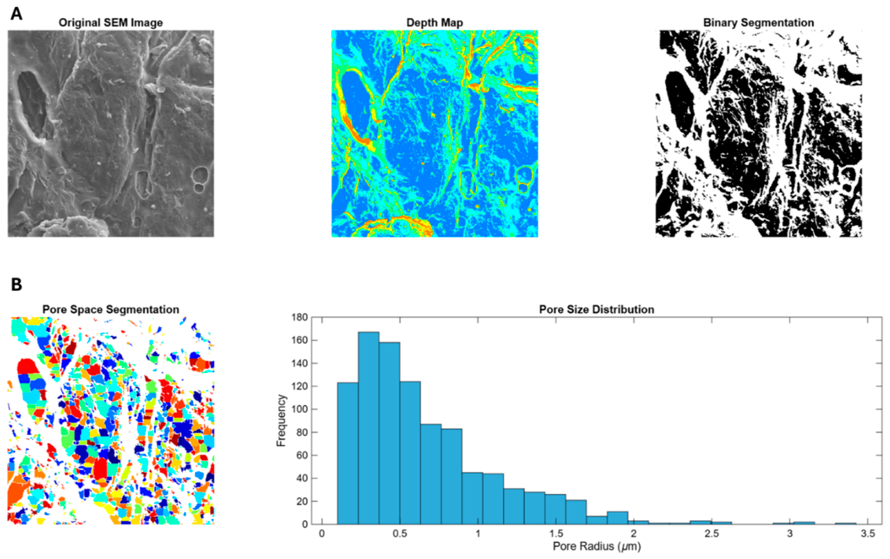
Figure 5.
MATLAB-based SEM image analysis of 3D-printed scaffolds, including surface topography, depth mapping, binary segmentation, and pore size distribution at different infill densities. (A) The scaffold with 50% infill exhibited a heterogeneous porous architecture, characterized by surface pores of up to 500 μm, along with smaller pores ranging from 1 to 20 μm. In the deeper regions of the scaffold, pores were predominantly distributed between 1 and 8 μm. (B) Scaffold with 60% infill exhibits a more homogeneous pore distribution (1–3.5 μm), with a dominant population of 1–2 μm pores; binary segmentation indicates increased pore depth through a higher fraction of dark regions. (C) Scaffold with 70% infill presents a more uniform and refined porous structure, with reduced pore size variability (0.2–1.5 μm) and a predominance of pores between 0.2–0.7μm.
Figure 5.
MATLAB-based SEM image analysis of 3D-printed scaffolds, including surface topography, depth mapping, binary segmentation, and pore size distribution at different infill densities. (A) The scaffold with 50% infill exhibited a heterogeneous porous architecture, characterized by surface pores of up to 500 μm, along with smaller pores ranging from 1 to 20 μm. In the deeper regions of the scaffold, pores were predominantly distributed between 1 and 8 μm. (B) Scaffold with 60% infill exhibits a more homogeneous pore distribution (1–3.5 μm), with a dominant population of 1–2 μm pores; binary segmentation indicates increased pore depth through a higher fraction of dark regions. (C) Scaffold with 70% infill presents a more uniform and refined porous structure, with reduced pore size variability (0.2–1.5 μm) and a predominance of pores between 0.2–0.7μm.
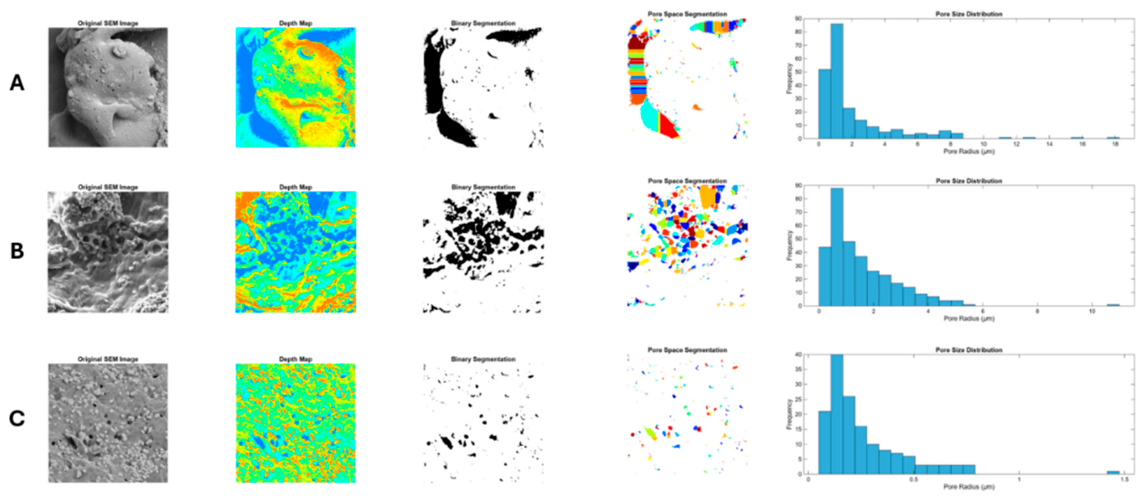
Figure 6.
Energy-dispersive X-ray spectroscopy (EDX) analysis of HAp/PLGA/CS scaffolds fabricated via freeze-drying. (A) Quantitative elemental composition of the scaffold, showing the relative abundance of the main constituent elements. (B) Representative EDX spectrum displaying the characteristic peaks corresponding to elements present in the scaffold matrix and their relative intensities.
Figure 6.
Energy-dispersive X-ray spectroscopy (EDX) analysis of HAp/PLGA/CS scaffolds fabricated via freeze-drying. (A) Quantitative elemental composition of the scaffold, showing the relative abundance of the main constituent elements. (B) Representative EDX spectrum displaying the characteristic peaks corresponding to elements present in the scaffold matrix and their relative intensities.
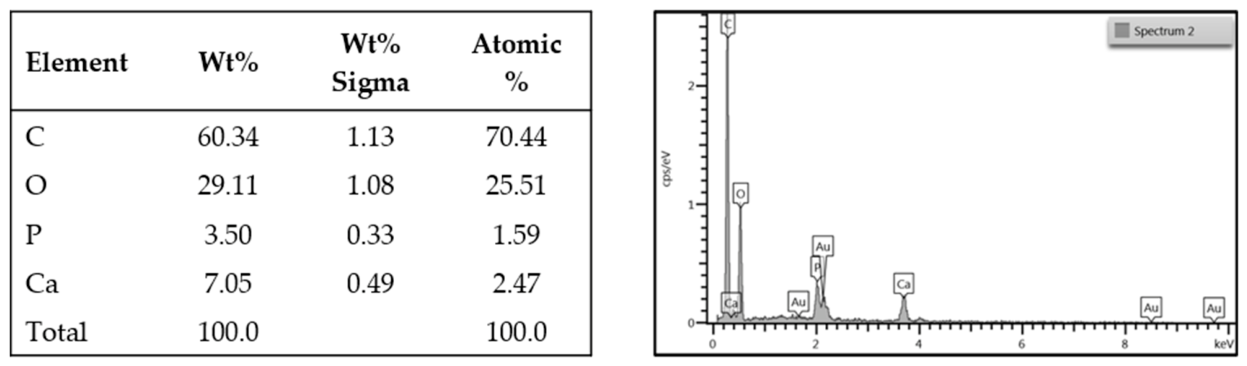
Figure 7.
Energy-dispersive X-ray spectroscopy (EDX) analysis of HAp/PLGA/CS scaffolds fabricated via 3D printing. (A) Quantitative elemental composition of the scaffold with 60% infill density, showing the relative abundance of the main constituent elements. (B) Representative EDX spectrum displaying the characteristic elemental peaks and their relative intensities within the scaffold matrix.
Figure 7.
Energy-dispersive X-ray spectroscopy (EDX) analysis of HAp/PLGA/CS scaffolds fabricated via 3D printing. (A) Quantitative elemental composition of the scaffold with 60% infill density, showing the relative abundance of the main constituent elements. (B) Representative EDX spectrum displaying the characteristic elemental peaks and their relative intensities within the scaffold matrix.
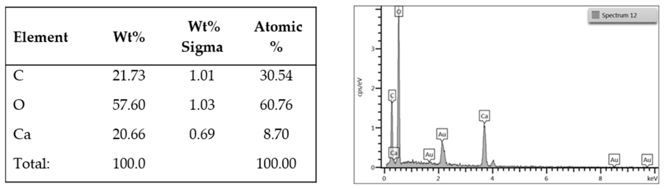
Figure 8.
Morphological and immunophenotypic characterization of human dental pulp stem cells (hDPSCs). (A) Representative micrograph showing colony formation units (CFUs) and fibroblast-like morphology of hDPSCs in culture (scale bar = 50 μm). (B) Flow cytometry histograms illustrating the expression of positive mesenchymal markers CD105, CD73, and CD90. (C) Flow cytometry histograms showing the unstained control and low expression of negative hematopoietic markers CD45 and CD34. (D) Quantitative summary of surface marker expression in hDPSCs.
Figure 8.
Morphological and immunophenotypic characterization of human dental pulp stem cells (hDPSCs). (A) Representative micrograph showing colony formation units (CFUs) and fibroblast-like morphology of hDPSCs in culture (scale bar = 50 μm). (B) Flow cytometry histograms illustrating the expression of positive mesenchymal markers CD105, CD73, and CD90. (C) Flow cytometry histograms showing the unstained control and low expression of negative hematopoietic markers CD45 and CD34. (D) Quantitative summary of surface marker expression in hDPSCs.
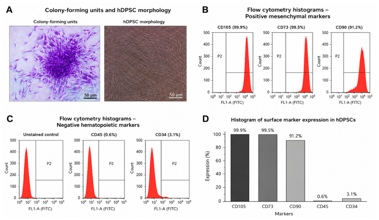

Table 1.
Primer sequences used for polymerase chain reaction (PCR).
| Gene | Forward (5’-3’) | Reverse (3’-5’) |
| Runx2 | CATCTAATGACACCACCAGGC | GCCTACAAAGGTGGGTTTGA |
| ALP | TCAGAAGCTCAACACCAACG | GTCAGGGACCTGGGCATT |
| OP | TGAAACGAGTCAGCTGGATGACCA | TGGCTGTGAAATTCATGGCTGTGG |
| OSX | TGGGAAAAGGGAGGGTAATC | CGGGACTCAACAACTCTGG |
| COL1 | TGACCTCAAGATGTGCCACT | ACCAGACATGCCTCTTGTCC |
| GAPDH | GAAGGTGAAGGTCGGAGTC | GAAGATGGTGATGGGATTTC |
Table 2.
Freeze-drying Scaffolds.
| Compound | Percentage % |
| Hydroxyapatite | 1.07 |
| PLGA | 4.34 |
| Chitosan | 8.69 |
| Chloroform | 86.8 |
Table 3.
3D-printing Scaffolds.
| Compound | Percentage % |
| Hydroxyapatite | 1.89 |
| PLGA | 7.55 |
| Chitosan | 15.09 |
| Xanthan gum | 18.87 |
* Xanthan gum and water were incorporated into the 3D-printing formulation to improve the flowability and printability of the material.
Table 4.
Mechanical stiffness of scaffolds obtained by finite element analysis (FEA).
| Model | Stiffness (MPa) | Scaffold type (fabrication method) |
| 4 | 40 | Freeze-drying |
| 7 | 19 | 3D printing |
| 1 | 13 | Freeze-drying |
| 3 | 9 | Freeze-drying |
| 5 | 7 | Freeze-drying |
| 6 | 6 | 3D printing |
| 2 | 4 | Freeze-drying |
Table 5.
Mechanical properties of the scaffolds produced by the two methods.
| Dimensions | Units | Mod.1 | Mod.2 | Mod.3 | Mod.4 | Mod.5 | Mod.6 | Mod.7 | Implant |
| Manufacturing | - | C. L. | C. L. | C. L. | C. L. | C. L. | 3 D | 3 D | - |
| Diameter | cm | 0.78 | 0.80 | 0.78 | 0.78 | 0.80 | 0.78 | 0.70 | 0.33 |
| Length | cm | 1.73 | 1.09 | 1.06 | 1.91 | 1.48 | 1.03 | 1.00 | 0.80 |
| Mass | g | 2.75 | 2.96 | 3.07 | 2.89 | 2.94 | 3.18 | 1.85 | 0.30 |
| Density | g/cm3 | 3.29 | 5.43 | 5.96 | 3.10 | 3.95 | 6.41 | 3.70 | 4.38 |
| Modulus of elasticity | Mpa | 13.0 | 4.0 | 9.0 | 40.0 | 7.0 | 6.0 | 19.8 | 10000.0 |
| Stress | Mpa | 5.50 | 1.80 | 2.00 | 6.00 | 2.00 | 1.90 | 8.80 |
Disclaimer/Publisher’s Note: The statements, opinions and data contained in all publications are solely those of the individual author(s) and contributor(s) and not of MDPI and/or the editor(s). MDPI and/or the editor(s) disclaim responsibility for any injury to people or property resulting from any ideas, methods, instructions or products referred to in the content. |
© 2026 by the authors. Licensee MDPI, Basel, Switzerland. This article is an open access article distributed under the terms and conditions of the Creative Commons Attribution (CC BY) license.
Copyright: This open access article is published under a Creative Commons CC BY 4.0 license, which permit the free download, distribution, and reuse, provided that the author and preprint are cited in any reuse.


