

Submitted:
11 July 2026
Posted:
13 July 2026
You are already at the latest version
Abstract
Low-altitude autonomous mobility research requires unmanned aerial vehicle platforms that are affordable, experimentally transparent, and safe enough for repeated indoor and near-ground validation. This paper presents a reproducible safety-aware ESP32-based quadrotor testbed designed as an open experimental platform rather than a sealed commercial flight product. The system integrates an ESP32 flight controller, an ESP32 remote controller, IMU-based attitude estimation, PID stabilization, PWM motor actuation, ESP-NOW communication, telemetry feedback, parameter synchronization, and over-the-air maintenance support. The platform is structured around three design objectives: reproducibility, firmware-level safety awareness, and blackbox-supported diagnosis . The safety architecture includes arming and disarming logic, throttle initialization checks, communication fail-safe, low-voltage warning, ESC-calibration isolation, visual state indication, and tilt/collision shutdown. The diagnostic layer records runtime variables, including battery voltage, compensation factors, attitude angles, PID outputs, offsets, motor commands, communication status, loop timing, and logging overhead. These data support post-flight analysis, controller tuning, offset correction, and repeatable comparison across experiments. Validation was conducted through staged ground tests and conservative indoor low-altitude hover trials. The results indicate that the platform can support short-duration stable hovering with pitch and roll deviations within approximately ±5°, end-to-end control response of about 50–80 ms, and indoor ESP-NOW latency of about 20–40 ms, while maintaining a total prototype cost below approximately USD 200. The contribution of this work is not maximum flight performance or full autonomous mission execution, but the integration of low cost, transparent firmware, explicit safety logic, and data-driven diagnostic workflow into a coherent quadrotor research testbed. The proposed platform provides a practical foundation for embedded-systems education, low-altitude UAV experimentation, and future extensions toward sensing, autonomy, and comparative controller evaluation.
Keywords:
quadrotor UAV
; ESP32
; low-altitude autonomous mobility
; safety-aware flight control
; blackbox diagnostics
; reproducible testbed
; ESP-NOW
; PID control
1. Introduction
The novelty of this study lies in treating a low-cost ESP32 quadrotor not as an assembly prototype, but as a reproducible safety-aware diagnostic testbed with explicit packet semantics, firmware-level safety states, and blackbox-supported tuning.
Low-altitude autonomous mobility has become an important
direction in the development of unmanned aerial systems, low-altitude economy,
and future three-dimensional transportation services. Although many studies
emphasize advanced navigation, cooperative routing, aerial task allocation, or
mission-level autonomy, these higher-level functions still depend on dependable
experimental platforms at the lower levels of sensing, control, communication,
safety response, and diagnostic feedback. Even when the immediate research
objective is modest, such as controlled hovering, short-range maneuvering, or
subsystem validation, the underlying vehicle must remain safe, repeatable, and
interpretable under repeated experiments.
This requirement creates a practical tension for researchers and
educators. Commercial flight controllers are mature and reliable for
operational use, but they often hide low-level implementation details behind
closed firmware, predefined telemetry interfaces, or highly abstract
configuration tools. As a result, they are not always suitable when the
research question concerns firmware timing, packet-level communication,
embedded safety logic, or blackbox-based diagnosis. A researcher may observe
whether a flight succeeds or fails, but may not be able to inspect the complete
chain from sensor readings, command validation, and control computation to
safety shutdown and post-flight logging.
Open-source autopilot ecosystems partly address this limitation
by providing source code, broad hardware support, estimator integration,
mission services, and rich communication interfaces. Platforms such as large
autopilot stacks are indispensable for advanced autonomy research and field
robotics. However, their strength can also become a limitation for early-stage
low-altitude laboratory studies. Their configuration complexity, hardware
dependencies, large code bases, and feature breadth may exceed what is
necessary when the goal is to study a compact interaction among IMU sensing,
PID stabilization, motor actuation, wireless command packets, safety state
transitions, and embedded logging. In this context, the present work does not
attempt to replace mature autopilot systems. Instead, it proposes a smaller and
more inspectable testbed for controlled experiments in which firmware behavior,
communication semantics, safety logic, and diagnostic data can be directly
observed and modified.
Low-cost microcontroller-based UAV platforms offer a promising
alternative for this purpose, but low cost alone does not make a platform
research-ready. Many low-cost quadrotor prototypes emphasize assembly, basic
hovering, or controller demonstration, while leaving several reproducibility
questions insufficiently addressed. For example, communication packet formats
may not be standardized, safety thresholds may be embedded as scattered
conditional statements, tuning histories may remain hidden in flash memory, and
flight behavior may be interpreted mainly through subjective visual
observation. These limitations make it difficult to compare repeated builds,
diagnose abnormal behavior, or teach students how engineering assumptions
influence flight safety.
The ESP32 microcontroller is attractive for such a testbed
because it provides low cost, sufficient embedded processing capability,
flexible I/O, wireless communication, and a large developer ecosystem.
Nevertheless, building a quadrotor around an ESP32 does not automatically
produce a reproducible or safe research platform. Low-cost inertial sensors are
vulnerable to vibration, bias, and drift; wireless command loss can cause
unsafe command persistence; and PID tuning decisions can become opaque when they
are based only on pilot perception. Therefore, an ESP32-based quadrotor should
be designed as a complete cyber-physical experimental system rather than as a
simple collection of inexpensive components.
This paper presents a reproducible safety-aware ESP32-based
quadrotor testbed for low-altitude autonomous mobility experiments. The
platform combines an ESP32 flight controller, an ESP32 remote controller,
IMU-based attitude estimation, PID stabilization, PWM motor actuation, ESP-NOW
communication, telemetry feedback, parameter synchronization, safety-state
indication, and blackbox-supported diagnosis. The focus is not maximum flight
performance or fully autonomous mission execution. Instead, the goal is to
provide a compact, low-cost, and experimentally transparent platform in which
sensing, control, communication, safety, and diagnosis can be inspected as an
integrated system.
The main contributions of this work are as follows:
- A reproducible ESP32-based quadrotor testbed is developed for indoor and near-ground low-altitude validation, with explicit documentation of hardware components, communication packets, task organization, parameter handling, and staged test procedures.
- A firmware-level safety architecture is integrated into the platform, including arming protection, throttle initialization checks, communication fail-safe, low-voltage warning, ESC-calibration isolation, visual state indication, and tilt/collision shutdown.
- A blackbox diagnostic workflow is embedded into the control process to record runtime variables such as battery voltage, compensation factors, attitude angles, PID outputs, offsets, motor commands, communication status, loop timing, and logging overhead.
- The platform architecture and safety workflow are formalized using UML diagrams to improve the clarity, traceability, and reproducibility of the firmware and operational logic.
- The testbed is validated through staged ground checks and conservative indoor low-altitude hover trials, demonstrating short-duration hovering within approximately ±5° in pitch and roll, end-to-end control response of about 50–80 ms, indoor ESP-NOW latency of about 20–40 ms, and a prototype cost below approximately USD 200.
The remainder of this paper is organized as follows. Section 2 reviews related work on quadrotor control, low-cost UAV
platforms, open-source autopilot ecosystems, safety-aware flight operation, and
blackbox-supported diagnosis. Section 3 describes
the platform architecture and reproducibility strategy. Section 4 presents the safety-aware control design and diagnostic
workflow. Section 5 explains the experimental setup and evaluation metrics. Section 6 reports the validation results. Section 7 discusses
implications, limitations, and positioning relative to commercial and
open-source alternatives. Section 8 concludes
the paper and outlines future work.
2. Related Work
Research on quadrotor UAVs covers a wide range of topics,
including flight dynamics, attitude estimation, control theory, embedded
implementation, communication, autonomy, and application-specific deployment.
The present study is positioned at the intersection of low-cost UAV testbeds,
embedded safety design, and blackbox-supported reproducibility. This section
reviews five related areas and clarifies the research gap addressed by the
proposed ESP32-based quadrotor platform.
2.1. Quadrotor Control and Low-Cost Platforms
Quadrotor control has been widely studied because the vehicle is
underactuated, nonlinear, and sensitive to sensor noise, motor imbalance, and
modeling uncertainty. Classical studies established the importance of attitude
estimation, motor mixing, feedback stabilization, and robust controller design
for indoor and outdoor flight [1,2,3,4]. PID-based control remains widely
used in practical quadrotor systems because it is computationally simple,
interpretable, and suitable for embedded implementation. Although more advanced
nonlinear, adaptive, and intelligent controllers have been proposed, PID
control continues to provide a useful baseline for educational platforms,
laboratory validation, and early-stage embedded experiments [5,6,9].
Low-cost quadrotor platforms have also been explored for
education, prototyping, and controller testing. These systems reduce the entry
barrier for students and researchers by using affordable airframes, commodity
inertial sensors, open development boards, and accessible software tools [8,14].
They are particularly useful when the research objective is not maximum flight
performance but hands-on understanding of sensing, actuation, communication,
and control. However, many low-cost platforms primarily emphasize assembly,
basic controller implementation, or successful hovering. They often provide
limited discussion of packet-level communication, firmware task organization,
safety state transitions, parameter recovery, and post-flight diagnostic data.
As a result, low cost alone does not guarantee that a platform is reproducible
or scientifically inspectable.
The proposed work builds on the educational and experimental
value of low-cost quadrotors but treats reproducibility as a primary design
objective. The platform is not presented merely as a vehicle that can fly; it
is documented as a cyber-physical testbed whose hardware configuration,
embedded tasks, packet definitions, safety mechanisms, and diagnostic records
are intended to be inspected and repeated across experiments.
2.2. Open-Source Autopilot Ecosystems
Open-source autopilot ecosystems, such as PX4 and ArduPilot, have
become essential tools for advanced UAV autonomy research because they provide
broad vehicle support, estimator integration, mission planning, telemetry
interfaces, parameter management, flight-operation documentation, and
community-tested safety features [15,16]. For outdoor
navigation, GPS-based missions, obstacle avoidance, multi-sensor fusion, and
field robotics, these ecosystems are difficult to replace. Recent UAV reviews
also show that modern copter systems increasingly rely on integrated computing
platforms, sophisticated sensing, and layered software architectures [7,10,13].
Nevertheless, large autopilot stacks are not always the best fit
for early-stage low-altitude laboratory studies. Their code bases,
configuration systems, hardware assumptions, and abstraction layers can make it
difficult for students or researchers to isolate a specific embedded-system
question. For example, when the goal is to examine how a microcontroller
handles IMU sampling, wireless command packets, arming conditions, failsafe
timing, PWM motor output, and blackbox logging, a compact architecture may be
more transparent than a full autopilot ecosystem. The use of a large stack can
also shift attention from the intended research question toward platform
configuration and integration overhead.
The proposed ESP32-based platform therefore complements rather
than competes with large autopilot systems. It is not intended to outperform
mature autopilots in navigation, estimator sophistication, or mission
capability. Instead, it provides a smaller and more inspectable baseline for
experiments that require direct access to low-level firmware behavior, safety
logic, and diagnostic data.
2.3. Safety-Aware Operation
Safety is a central issue in UAV experimentation, especially for
indoor and low-altitude environments where operators, students, equipment,
walls, ceilings, and protective nets may be close to the airframe. Standard UAV
safety concerns include accidental arming, stale commands during communication
loss, low-voltage operation, motor saturation, incorrect ESC calibration,
excessive tilt, collision, and unclear operator feedback. Prior UAV surveys
have emphasized the increasing importance of system reliability, operational
safety, computing-platform robustness, and application-specific risk management
in unmanned aircraft systems [7,10,12,13].
For low-cost educational and laboratory platforms, safety
mechanisms are sometimes treated as procedural notes or implementation details
rather than as a coherent architecture. This is problematic because repeated
experimental use depends not only on whether the controller can stabilize the
vehicle, but also on whether the system can prevent unsafe startup, respond
predictably to link loss, isolate high-risk calibration modes, and communicate
its state clearly to the operator. In low-altitude testing, a short delay in
failsafe response or an ambiguous armed/disarmed state can be as important as
the nominal control performance.
The present study treats safety as a firmware-level architectural
layer. The proposed platform incorporates throttle initialization checks,
sustained arming gestures, communication fail-safe, ESC-calibration isolation,
low-voltage warning, visual state indication, and tilt/collision shutdown.
These mechanisms are designed to make unsafe transitions difficult while making
emergency shutdown fast and deterministic. This orientation is especially
important for repeated indoor validation and student-facing embedded-system
experiments.
2.4. Blackbox Diagnostics and Reproducibility
Blackbox logging has become an important practical tool in UAV
development because flight behavior cannot always be interpreted from visual
observation alone. Oscillation, drift, delayed response, voltage sag, motor
imbalance, packet gaps, and sensor bias may produce similar outward symptoms.
Without runtime records, tuning decisions may rely heavily on pilot perception
or trial-and-error adjustment. This limits reproducibility, especially when
different users or student groups build similar platforms with slightly
different wiring, sensor mounting, frame stiffness, propeller balance, or
center-of-gravity conditions.
Diagnostic logging can improve this process by connecting
observed flight behavior with measurable internal variables. Relevant data
include attitude angles, angular rates, PID outputs, motor commands, offsets,
battery voltage, voltage-compensation factors, communication status, loop
timing, logging overhead, and safety-state flags. This need is consistent with
broader concerns in UAV computing-platform reliability and experimental
repeatability, where hardware variability, embedded timing, and system-level
interactions can affect the interpretation of UAV behavior [8,13,14].
In many low-cost UAV studies, however, blackbox data are either
absent, treated as a debugging convenience, or not integrated into the research
contribution. The present work elevates blackbox diagnostics to a core part of
reproducibility. The platform records runtime evidence that supports
post-flight interpretation, PID tuning, offset correction, and comparison
across repeated trials. In this sense, reproducibility is not limited to
rebuilding the same hardware; it also includes the ability to explain and
revisit the tuning pathway that led to a stable configuration.
2.5. Research Gap Summary
The literature indicates that quadrotor control, low-cost UAV
platforms, UAV computing architectures, safety mechanisms, and diagnostic
logging are all well-established topics [1,2,3,4,5,6,7,8,9,10,11,12,13,14]. However,
several gaps remain for low-altitude experimental testbeds.
First, there is still a need for compact UAV platforms that are
low cost, inspectable, and suitable for microcontroller-level experiments
without the full complexity of large autopilot stacks. Second, many low-cost
platforms do not present safety mechanisms as an integrated firmware
architecture with explicit state transitions, thresholds, and operator-visible
feedback. Third, blackbox-supported diagnosis is often underdeveloped as a
formal component of reproducibility, even though it strongly affects whether
repeated experiments can be interpreted and compared. Fourth, the connection
between system architecture, safety workflow, diagnostic data, and experimental
validation is not always represented clearly enough for replication by other
researchers or student cohorts.
This study addresses these gaps by presenting a reproducible
safety-aware ESP32-based quadrotor testbed for low-altitude autonomous mobility
experiments. The platform combines low-cost hardware, explicit ESP-NOW packet
definitions, PID-based stabilization, firmware-level safety logic, parameter
recovery, blackbox runtime logging, and staged indoor validation. By
representing the architecture and workflow through UML diagrams and supporting
the results with diagnostic records, the work contributes an experimentally
transparent testbed rather than only a one-off quadrotor prototype.
3. Platform Architecture and Reproducibility Strategy
3.1. Overall Architecture
The proposed system adopts a distributed ESP32-based architecture composed of two main subsystems: an onboard flight-control unit mounted on the quadrotor and a remote-control unit operated by the user. This separation was selected to make the experimental structure explicit. The onboard unit is responsible for sensing, attitude estimation, PID stabilization, motor actuation, safety monitoring, telemetry generation, and blackbox recording. The remote unit is responsible for joystick command acquisition, parameter update requests, telemetry display, and operator interaction. This organization preserves a clear boundary between command generation and safety-critical execution.
The platform is intended for low-altitude indoor and near-ground experiments rather than full autonomous mission execution. Therefore, the architectural priority is not maximum flight performance, but transparent integration of sensing, control, communication, safety, and diagnosis. The UAV retains final authority for arming, disarming, failsafe response, and motor shutdown. The remote controller can request parameter updates and transmit operator commands, but unsafe-state detection and emergency response are executed onboard. This design reduces the risk that a lost or delayed transmitter command will cause stale control input to persist.
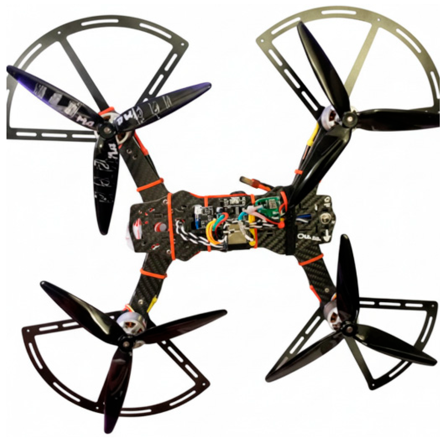
Figure 1.
Assembled ESP32-based quadrotor prototype used for low-altitude indoor validation.
3.2. Hardware Configuration
The platform was built from commercially available components so that other researchers or student groups can reconstruct the system with minimal dependence on proprietary hardware. The basic configuration includes two ESP32 DevKit V1 boards, an MPU6050 or compatible IMU module, four brushless motors, four ESCs, a LiPo battery, an X-type quadrotor frame, a battery voltage divider, LED indicators, and ESP-NOW wireless communication. One ESP32 is used as the flight controller, while the second ESP32 is used as the remote controller.
The ESP32 was selected because it integrates Wi-Fi/Bluetooth connectivity, flexible peripheral interfaces, and sufficient embedded processing capability for compact experimental platforms [18]. The MPU6050 was used as a low-cost six-axis IMU reference because its register-level configuration and product specifications are publicly documented [19,20].
The recommended bill of materials is summarized in Table 1. The total hardware cost remained below approximately NT$6,000–6,500, or roughly USD 200 depending on local sourcing. This cost range is low enough for repeated prototyping and educational use, while still including the essential components needed for embedded UAV experimentation: inertial sensing, brushless propulsion, wireless communication, voltage monitoring, telemetry, and safety-state indication.
During development, both 7-inch and 5-inch class configurations were considered. The larger 7-inch configuration with relatively low-KV motors and a 4S battery was preferred during safer validation because it provided gentler response and improved observability during short indoor hover trials. The smaller 5-inch class confirmed that the software architecture is not tied to only one airframe size. The use of accessible mounting, visible wiring, and replaceable components also supports reproducibility, because many early UAV problems originate from motor-order mistakes, vibration transmission, unstable power wiring, or sensor mounting rather than from control theory alone.
3.3. Software Architecture and UML Representation
The onboard flight-control software is organized as a set of interacting functional modules. The main modules include IMU sensing, attitude estimation, PID control, motor mixing, PWM output, voltage monitoring, safety management, telemetry transmission, parameter storage, OTA maintenance, and blackbox logging. This modular structure supports reproducibility because each function has a defined role and can be inspected, modified, or replaced without redesigning the entire system.
In the tested implementation, the ESP32 dual-core structure is used to separate time-sensitive control tasks from supporting tasks. Core 1 is assigned to IMU acquisition, attitude estimation, PID computation, and yaw-related calculations. Core 0 handles motor output, throttle smoothing, blackbox logging, safety checking, LED state indication, telemetry transmission, and OTA-related functions. This arrangement does not eliminate all timing constraints, but it makes the software timing assumptions explicit and easier to evaluate.
The sensing stack supports two operating paths based on the documented MPU6050 configuration and data-access modes [19,20]. The first path uses the MPU6050 DMP mode at approximately 200 Hz, which provides preprocessed attitude information with lower computational burden. The second path uses raw-data processing at up to approximately 1000 Hz, which offers greater transparency and lower processing delay but requires explicit filtering, offset handling, and attitude estimation in the firmware. Supporting both paths allows the developer to trade computational simplicity against diagnostic transparency and control-loop responsiveness.
Figure 2 presents the UML class diagram of the proposed platform. The diagram represents the quadrotor testbed as an integrated cyber-physical system rather than as a collection of disconnected scripts. The QuadrotorPlatform class composes the FlightController, RemoteController, CommunicationManager, SafetyManager, BlackboxLogger, and ParameterStore classes. The FlightController depends on the IMUSensor, PIDController, and MotorMixer classes for sensing, control computation, and motor-output allocation. The SafetyManager monitors the flight controller and communication manager, while the BlackboxLogger records runtime data from the control, safety, and communication layers. This representation clarifies how safety and diagnosis are embedded in the system architecture instead of being treated as external accessories.
3.4. Communication and Parameter Synchronization
Communication between the remote controller and the UAV is implemented using ESP-NOW, a connectionless Wi-Fi communication protocol defined by Espressif for direct device-to-device data exchange [17]. This communication method was selected because it avoids router dependence, reduces setup overhead, and provides sufficient responsiveness for short-range indoor low-altitude experiments. Three packet families are defined to support command, telemetry, and parameter synchronization.
ESP-NOW was selected because it is a connectionless Wi-Fi communication protocol defined by Espressif that can transmit application data directly between Wi-Fi devices without a conventional network connection [17].
The real-time control packet uses the header 0xAA and is transmitted from the remote controller to the UAV. It contains throttle, yaw, pitch, roll, and checksum fields. In the reference implementation, the packet length is 6 bytes and the transmission interval is approximately 20 ms. The telemetry packet uses the header 0xBB and is transmitted from the UAV to the remote controller. It reports flight state, battery voltage, signal quality or packet-gap information, mixed throttle, yaw correction, reserved fields, and checksum. The parameter packet uses the header 0xCC and supports bidirectional parameter synchronization, including PID gains, offsets, low-pass filter settings, maximum angle, expo, throttle midpoint, voltage-adjust gain, and system status bits.
Table 2 summarizes the three packet types. The use of explicit headers, fixed packet roles, and checksum validation supports reproducible communication semantics. It also simplifies debugging because command loss, telemetry delay, and parameter mismatch can be interpreted at the packet level rather than treated as opaque wireless behavior.
Parameter governance is an important part of the architecture. The platform distinguishes among three parameter sources: built-in safe defaults, flash-stored parameters from earlier tuning sessions, and temporary live parameters transmitted from the remote controller. This distinction is necessary because low-altitude UAV experiments are frequently interrupted by partial tuning attempts. Without a safe recovery mechanism, an unstable parameter set may remain stored in nonvolatile memory and affect the next experiment. By explicitly modeling safe defaults, flash storage, and live tuning, the system makes tuning history visible and recoverable.
3.5. Reproducibility Strategy
Reproducibility is addressed at five levels: hardware, software, communication, procedure, and diagnosis. Hardware reproducibility is supported by the use of commercially available parts and equivalent replacement options. Software reproducibility is supported by modular task separation, explicit class-level representation, and documented control-loop responsibilities. Communication reproducibility is supported by fixed packet families, headers, payload definitions, and checksum validation. Procedural reproducibility is supported by staged assembly, propeller-off verification, motor-order testing, ground checks, indoor hover trials, and post-flight troubleshooting. Diagnostic reproducibility is supported by blackbox logging of runtime variables and by using these records to guide offset correction and PID tuning.
Figure 3 presents the UML activity diagram of the safety-aware flight workflow. The diagram begins with remote and UAV power-on procedures, initialization, ESP-NOW link establishment, parameter synchronization, packet validation, battery checking, throttle checking, and arming-condition verification. Only after valid communication, safe throttle state, sensor readiness, and a sustained arming gesture are confirmed does the system enter the armed state. During operation, IMU acquisition, attitude estimation, PID computation, motor mixing, telemetry exchange, safety monitoring, and blackbox logging proceed as coordinated activities. If an unsafe condition is detected, the UAV enters emergency disarm, stops the motors, logs the event, and presents a warning state to the operator. After landing or disarming, the blackbox log can be exported and analyzed to tune parameters for the next experiment.
This workflow shows that reproducibility is not limited to rebuilding the same airframe. It also requires repeatable startup conditions, known parameter states, validated communication, explicit arming logic, deterministic shutdown behavior, and diagnostic evidence after each test. The proposed architecture therefore treats reproducibility as an operational property of the entire experimental process rather than only as a hardware documentation problem.
4. Safety-Aware Flight Control and Blackbox Design
4.1. Safety-Aware Control Principle
Safety-aware design is the central distinguishing feature of the proposed platform. In many low-cost UAV prototypes, safety functions are treated as separate checks, operator habits, or scattered conditional statements. In this work, safety is implemented as a firmware-level architectural layer that directly governs the transition among disarmed, armed, calibration, warning, failsafe, and emergency-disarm states. This approach is important for low-altitude indoor experiments because the vehicle may operate near people, equipment, walls, ceilings, or protective nets.
The proposed safety design follows two principles. First, entering an active motor state should be conservative. The UAV should not arm unless the throttle state is safe, the operator command is deliberate, the IMU is ready, and communication is valid. Second, leaving an active motor state should be fast and deterministic. If communication loss, excessive tilt, collision-like behavior, invalid parameters, or unsafe voltage conditions are detected, the onboard controller should be able to disarm the vehicle without depending on the remote controller to transmit a final zero-throttle command.
This design makes the UAV itself the final decision-maker for safety-critical shutdown. The remote controller provides human input, telemetry display, and parameter synchronization, but the onboard flight controller continuously evaluates whether the current state remains safe for motor actuation. This separation prevents stale remote commands from persisting during link loss and ensures that emergency response is performed by the system closest to the motors.
4.2. Arming, Disarming, and State Protection
Arming and disarming are implemented as deliberate state transitions rather than simple motor toggles. At startup, the UAV enters a disarmed state. Motor output remains disabled while the system initializes the IMU, PWM output, communication interface, parameter store, voltage monitor, LED indicators, and blackbox logging functions. The platform then waits for valid control packets and safe input conditions before accepting an arming request.
The arming procedure requires three conditions. First, the throttle must be at or near its minimum value. Second, the communication link must be valid and recent control packets must pass checksum verification. Third, the operator must perform a sustained inward-stick arming gesture for approximately 800 ms. This sustained-gesture requirement reduces the probability of accidental arming caused by joystick noise, startup transients, or momentary input mistakes.
Disarming can occur through either an explicit operator command or an automatic safety response. The automatic path has priority over normal operation. When the onboard controller detects a critical unsafe condition, the system enters emergency disarm, disables motor output, resets control-related states when necessary, records the event, and presents a warning indication to the operator. This asymmetry is intentional: arming should be difficult and intentional, while disarming should be immediate and conservative.
4.3. Communication Fail-Safe and Packet Validation
The flight-control system uses ESP-NOW communication between the remote controller and the UAV. Because ESP-NOW is a packet-based and connectionless device-to-device communication mechanism, the UAV-side controller explicitly checks packet validity and packet freshness before accepting control commands [17]. Wireless communication may be interrupted by distance, interference, power instability, or software faults; therefore, the UAV does not assume that a lost remote controller can transmit a safe stop command. Instead, the onboard controller measures the age of the most recent valid control packet.
Because ESP-NOW communication is packet-based and connectionless, the UAV-side controller explicitly checks packet validity and packet freshness before accepting control commands [17].
The real-time control packet uses the header 0xAA and includes throttle, yaw, pitch, roll, and checksum fields. A packet is accepted only when the header and checksum are valid. If no valid 0xAA packet is received within approximately 0.5 s, the UAV triggers the communication fail-safe and disables motor output. This threshold is short enough to prevent stale-command flight while still allowing brief packet-level irregularities to be tolerated. On the remote side, telemetry return is monitored separately, and a longer warning threshold can be used to avoid excessive false offline indications.
Packet validation is therefore part of the safety architecture rather than merely a communication feature. The UAV treats command freshness and packet integrity as prerequisites for continued motor actuation. This makes the control path reproducible because the conditions under which a command is accepted, rejected, or timed out are explicitly defined.
4.4. ESC Calibration Isolation and Startup Safety
ESC calibration is one of the highest-risk procedures in a low-cost quadrotor platform because it may require full-throttle signal output during calibration. If this mode is accidentally entered while the battery and propellers are installed, the vehicle can generate dangerous thrust. For this reason, the proposed platform isolates ESC calibration from normal flight logic.
Calibration mode is entered only through an explicit high-risk condition or dedicated setup procedure. During calibration, normal arming and flight-control functions are inhibited, and a distinct warning state is shown through LED indication or operator feedback. The purpose is to prevent a full-throttle calibration signal from being confused with a normal motor command. In addition, the experimental procedure requires propeller-off verification and careful power handling before any calibration or motor-order test.
This calibration isolation is important for reproducibility because many first-flight failures are caused by incorrect ESC setup, wrong motor order, wrong rotation direction, or unsafe calibration behavior. By making calibration a separated state, the platform reduces the chance that setup procedures will contaminate normal flight experiments.
4.5. Voltage Monitoring, Tilt Protection, and Collision Shutdown
Battery voltage affects both safety and control quality. As the LiPo battery discharges, available thrust decreases and the vehicle may become less responsive even when the command signal remains unchanged. The platform therefore uses battery voltage for both warning and compensation. A voltage divider connected to the ESP32 ADC provides battery-voltage feedback. The measured voltage is used to generate low-voltage warnings and to compute compensation factors for pitch, roll, and yaw control support.
Pitch and roll compensation are treated as thrust-related quantities because thrust is related to motor voltage and propeller response. Yaw compensation is handled more conservatively because yaw authority depends on torque imbalance rather than direct vertical thrust alone. Compensation values are bounded so that voltage correction does not become an unsafe amplification mechanism. If the voltage falls below a critical threshold, the system warns the operator and recommends landing rather than continuing normal operation.
Tilt and collision protection address hazards that occur after abnormal motion or impact. If pitch or roll exceeds a predefined safe angle, or if acceleration indicates a collision-like event, the onboard controller disables motor output. This prevents propellers from continuing to spin after a tip-over, ground strike, wall contact, or protective-net collision. These protections are especially important in indoor low-altitude validation, where a failed hover test can rapidly become a mechanical or safety hazard.
4.6. Visual State Indication
The platform uses LED or display-based state indication to make internal safety states visible to the operator. The system distinguishes among connected/disarmed, armed, communication-loss, low-voltage, calibration, OTA/debug, and warning states. Although state indication may appear simple compared with control algorithms, it plays an important role in safe repeated experimentation.
A UAV that does not clearly communicate whether it is armed, disarmed, calibrating, disconnected, or in failsafe mode is difficult to operate safely. Visual feedback also supports reproducibility because different users can follow the same operational cues during setup, testing, failure response, and post-flight review. In a student-facing or multi-user experimental environment, clear state indication reduces dependence on undocumented operator experience.
4.7. Blackbox Logging Design
Blackbox diagnostics convert safety-aware flight control from a purely reactive system into a learning and reproducibility workflow. The proposed platform records runtime variables during operation so that observed flight behavior can be interpreted after the test. The recorded variables include battery voltage, voltage-compensation factors, pitch and roll angles, yaw-related signals, PID gains, control corrections, motor commands, arming state, loop frequency, communication status, logging overhead, and selected diagnostic flags.
These data are necessary because different abnormal behaviors can look similar during flight. For example, persistent drift may be caused by static offset bias, center-of-gravity imbalance, or motor mismatch. Oscillation may be caused by excessive proportional gain, derivative noise, insufficient filtering, or mechanical vibration. Weak response may result from voltage sag rather than poor PID tuning. A sudden shutdown may indicate communication fail-safe activation rather than controller instability. Blackbox records allow these cases to be separated using internal evidence instead of subjective observation alone.
The diagnostic layer is designed to be lightweight enough that it does not prevent basic real-time operation. Representative logs include loop rates on the order of 1000 Hz, battery voltage around 16.49 V, compensation factor around 0.97x, offsets such as P = +0.35, R = −2.13, and Y = +3.90, DMP success of 100%, and average write time on the order of microseconds. These values are build-specific, but they demonstrate the type of runtime evidence required for post-flight interpretation.
4.8. Blackbox-Supported Tuning Workflow
The blackbox workflow follows a repeated engineering cycle: conduct a controlled test, export the runtime log, identify abnormal patterns, adjust one parameter group, and repeat the test under similar conditions. This workflow is deliberately conservative. It avoids changing many parameters at once, because simultaneous changes can make the cause of improvement or degradation difficult to identify.
If the log shows persistent drift with low oscillation, offset correction is considered before increasing PID gains. If the log shows rapid alternating correction around the setpoint, proportional gain, derivative gain, or derivative filtering is reviewed. If motor outputs become uneven or saturated, motor order, propeller condition, frame balance, and center of gravity are checked. If control response weakens as battery voltage declines, the voltage-compensation factor and battery condition are inspected. If packet gaps coincide with sudden motor shutdown, communication quality and failsafe timing are examined.
This diagnostic workflow strengthens reproducibility in two ways. First, it documents why a parameter change was made. Second, it enables different users or student groups to compare similar symptoms across different builds. The platform is therefore reproducible not only because its hardware and firmware can be reconstructed, but also because its tuning and troubleshooting process can be revisited using recorded evidence.
Table 3 summarizes the main safety mechanisms embedded in the proposed platform.
5. Experimental Setup and Evaluation Metrics
5.1. Experimental Scope and Test Environment
Experimental validation was designed to evaluate whether the proposed ESP32-based quadrotor testbed can support safe, repeatable, and interpretable low-altitude experiments. The goal was not to demonstrate aggressive flight, outdoor navigation, GPS-based autonomy, or obstacle avoidance. Instead, the validation focused on short-duration indoor hover, communication responsiveness, safety-state behavior, and blackbox-supported diagnosis.
All free-flight tests were conducted indoors in a controlled low-altitude environment. The test area provided a flat takeoff surface, sufficient side clearance, operator separation, visual observation of LED states, and emergency access for power disconnection. The tests were performed conservatively, with low altitude, short duration, no aggressive maneuvering, and no autonomous waypoint execution. This scope is consistent with the intended role of the platform as a transparent laboratory testbed for embedded UAV experimentation rather than as a production-grade autopilot system.
Two prototype scales were considered during development. A larger 7-inch class configuration with lower-KV motors and a 4S battery was used for safer early-stage validation because it provided gentler dynamic response and improved observability during indoor hover tests. A smaller 5-inch class configuration was also used to confirm that the architecture was not tied to a single airframe size. Both configurations shared the same basic ESP32-based control architecture, packet structure, safety logic, and blackbox-supported tuning workflow.
5.2. Staged Validation Procedure
The validation procedure followed a staged risk-reduction sequence. This staged approach was necessary because quadrotor experiments can fail due to wiring mistakes, incorrect motor order, unstable power distribution, wrong sensor orientation, unsafe calibration behavior, or communication loss before any meaningful control performance can be evaluated.
The first stage was propeller-off verification. In this stage, the system was powered and initialized without propellers installed. The purpose was to confirm IMU initialization, ESP32 startup behavior, PWM signal generation, telemetry exchange, parameter loading, LED state indication, blackbox file creation, and communication-packet validation. This stage also allowed the developer to verify that the UAV remained disarmed at startup and did not generate unsafe motor commands.
The second stage was motor-order and ESC verification. The four motors were tested individually to confirm that the physical motor locations, rotation directions, and software motor-mixing order were consistent with the defined X-frame configuration. ESC calibration was kept isolated from normal flight logic. Calibration-related tests were performed only under controlled setup conditions because calibration can involve high-throttle signal output.
The third stage was ground safety verification. This stage tested arming protection, throttle-minimum checking, sustained inward-stick arming logic, communication fail-safe, low-voltage warning behavior, and visual state indication. The UAV-side fail-safe was verified by interrupting valid command-packet reception and checking whether motor output was disabled after the defined timeout. Tilt or collision-related protection was evaluated under controlled non-flight or low-risk conditions.
The fourth stage was conservative indoor hover validation. After the previous stages were completed, short low-altitude hover trials were performed. The purpose was to confirm that the integrated system could support stable short-duration hovering, maintain practical control responsiveness, transmit telemetry, and record diagnostically useful blackbox data during operation. After each test, the blackbox log was exported and reviewed to guide parameter adjustment.
5.3. Measurement Methodology
Evaluation metrics were selected to match the purpose of the platform. The measured quantities focused on attitude stability, control responsiveness, wireless latency, fail-safe behavior, logging overhead, and cost. The metrics were not intended to provide a full flight-envelope characterization; rather, they were used to determine whether the testbed was suitable for repeated indoor low-altitude experimentation.
Hover attitude deviation was evaluated using logged pitch and roll angles during short indoor hover trials. The deviation was interpreted as the observed range of pitch and roll around the nominal hover attitude. The target acceptance logic was that the vehicle should remain within approximately ±5° during short-duration indoor hover without entering an unsafe state. This metric is reported in Figure 4(a).
Control response time was defined as the end-to-end delay from remote input change to the corresponding motor-output update. This includes joystick sampling, control-packet generation, wireless transmission, packet validation, command parsing, PID-related processing, motor mixing, and PWM update. The observed response range was approximately 50–80 ms under the tested indoor conditions. This metric is summarized in Figure 4(b).
Wireless latency was evaluated at the packet-communication level for the indoor ESP-NOW link. The observed packet-level latency was approximately 20–40 ms, which was sufficient for the intended low-altitude manual validation and telemetry feedback. Control packets were transmitted at approximately 20 ms intervals, corresponding to about 50 Hz command updates. These communication-related metrics are summarized in Figure 4(b).
Motor-output behavior was evaluated using blackbox records of the four motor commands. The purpose was not to identify an optimal motor allocation, but to confirm that the motor outputs remained bounded and diagnostically interpretable during stable hover. Representative motor-output traces and battery-state information are shown in Figure 4(c).
Battery-state monitoring was evaluated through the logged battery voltage and compensation factor. Representative blackbox data showed a battery voltage around 16.49 V and a compensation factor of approximately 0.97x. These values were used to verify that the voltage-monitoring and compensation pipeline produced interpretable runtime evidence during testing.
Logging performance was evaluated using blackbox diagnostic records, including loop rate, entry count, DMP success rate, and average log write time. Representative data included PID/motor loop operation around 1000 Hz, DMP success of 100%, average log write time on the order of microseconds, and a log entry count of 1004 out of 1800 entries. These metrics are summarized in Figure 4(d).
System cost was estimated from the recommended bill of materials. The prototype remained below approximately USD 200, depending on local sourcing and equivalent component selection. Cost was included as an evaluation metric because the platform is intended for reproducible laboratory construction, education, and repeated prototyping.
5.4. Safety Evaluation
Safety evaluation focused on whether the platform responded as designed under scripted abnormal or boundary conditions. The tested safety functions included arming protection, communication fail-safe, ESC-calibration isolation, low-voltage warning, visual state indication, tilt protection, collision-like shutdown, and safe default recovery.
Arming protection was evaluated by attempting startup and arming under unsafe or incomplete conditions, including non-minimum throttle, invalid packet state, or insufficient arming gesture duration. The expected behavior was that the UAV should remain disarmed and provide a safe-state indication.
Communication fail-safe was evaluated by interrupting valid control-packet reception. The expected behavior was that the UAV should disable motor output when no valid 0xAA control packet was received for approximately 0.5 s. This test confirmed that the aircraft, rather than the remote controller, remained responsible for final safety shutdown.
ESC-calibration isolation was evaluated by confirming that calibration behavior remained separated from normal flight operation. The expected behavior was that calibration mode could not be confused with normal armed flight and that a distinct warning state would be presented.
Tilt and collision protection were evaluated under controlled low-risk conditions by verifying that excessive attitude or collision-like indicators could force motor shutdown. The expected behavior was that the platform would enter emergency disarm, stop motors, record the event, and show a warning state.
5.5. Acceptance Logic and Figure Mapping
The acceptance logic was defined according to the intended use case of a low-altitude experimental testbed. The platform was considered suitable for the target validation scope if it satisfied the following criteria: successful staged ground verification, correct motor-order behavior, valid packet exchange, stable short-duration indoor hover within approximately ±5° pitch/roll deviation, end-to-end control response of about 50–80 ms, indoor ESP-NOW latency of about 20–40 ms, correct fail-safe response after approximately 0.5 s without valid command packets, diagnostically useful blackbox records, and total prototype cost below approximately USD 200.
Figure 4 summarizes the main validation evidence. Figure 4(a) reports hover attitude behavior. Figure 4(b) summarizes control response and communication timing. Figure 4(c) shows representative motor-output behavior and battery-state information. Figure 4(d) summarizes blackbox diagnostic indicators, including offsets, loop rate, DMP success, log write time, log entries, safety validation, and prototype cost.
Table 4 summarizes the core evaluation metrics and acceptance logic used in the condensed validation study.
6. Results
6.1. Platform Integration and Ground Verification
The implementation results confirm that the proposed ESP32-based quadrotor testbed can integrate sensing, actuation, wireless communication, safety-state management, parameter handling, and blackbox diagnostics within a compact low-cost architecture. The system operated as a coherent embedded platform rather than as a collection of disconnected experimental scripts. Both the larger 7-inch configuration and the smaller 5-inch class configuration preserved the same basic control structure, packet definitions, safety logic, and diagnostic workflow.
Ground verification was completed before propeller-on hover testing. The verification process confirmed IMU initialization, PWM signal generation, motor-order testing, ESC setup isolation, ESP-NOW packet exchange, telemetry feedback, parameter synchronization, LED state indication, and blackbox export. This stage was important because many early UAV failures arise from incorrect motor mapping, unstable wiring, wrong sensor orientation, or unsafe calibration behavior. By identifying these issues before free flight, the platform reduced the risk associated with indoor low-altitude validation.
6.2. Hover Attitude Stability
Short-duration indoor hover trials showed that the platform could maintain stable low-altitude flight under conservative test conditions. As shown in Figure 4(a), the logged pitch and roll angles remained within approximately ±5° around the nominal hover attitude during representative indoor hover testing. This result indicates that the combined IMU sensing, attitude estimation, PID stabilization, motor mixing, and PWM motor-output pipeline was sufficient for the intended low-altitude experimental scope.
This result should be interpreted as evidence of practical short-duration hover capability rather than high-performance flight control. The test did not evaluate aggressive maneuvering, outdoor disturbance rejection, GPS navigation, trajectory tracking, or autonomous mission execution. Nevertheless, the observed hover behavior is adequate for the proposed testbed role, because the platform is intended to support reproducible embedded-systems experiments, safety-state validation, and blackbox-supported controller tuning.
6.3. Communication and Control Timing
The communication and timing results indicate that the ESP-NOW link provided practical responsiveness for the target indoor use case. As summarized in Figure 4(b), the observed indoor ESP-NOW packet-level latency was approximately 20–40 ms. The real-time control packet was transmitted at approximately 20 ms intervals, corresponding to about 50 Hz command updates. This update rate was sufficient for manual low-altitude testing, telemetry feedback, and parameter interaction during controlled experiments.
The measured end-to-end control response time was approximately 50–80 ms. This range includes joystick sampling, packet generation, wireless transmission, packet validation, command parsing, control computation, motor mixing, and PWM motor-output update. Although this response time is not intended to compete with high-performance flight controllers, it is appropriate for conservative indoor low-altitude validation. The result also supports the architectural decision to keep the wireless link simple and infrastructure-free rather than relying on a router-based communication setup.
6.4. Motor Output and Battery-State Evidence
Representative motor-output traces are shown in Figure 4(c). During the short hover test, the four motor commands remained bounded and showed stable balancing behavior. The purpose of this result is not to claim optimal motor allocation, but to demonstrate that the motor-output data were available, interpretable, and suitable for post-flight diagnosis. Uneven motor output, saturation, or unstable correction behavior can therefore be detected through blackbox review rather than inferred only from visual observation.
The same panel also reports representative battery-state evidence. The logged battery voltage was approximately 16.49 V, and the voltage-compensation factor was approximately 0.97x. These values demonstrate that the voltage-monitoring and compensation pipeline produced usable runtime information during operation. This is important because battery condition affects thrust availability and can influence perceived controller responsiveness. Including voltage and compensation data in the diagnostic record helps distinguish voltage-related behavior from PID tuning problems.
6.5. Safety-Mechanism Verification
The safety verification results showed that the main safety mechanisms behaved as designed under staged test conditions. Arming protection blocked motor activation when throttle state, packet validity, or arming-gesture duration did not satisfy the required conditions. Communication fail-safe disabled motor output when no valid 0xAA control packet was received for approximately 0.5 s. ESC calibration remained isolated from normal flight operation. Low-voltage warning and visual state indication were observable during testing. Tilt or collision-related conditions could trigger emergency disarm and motor shutdown under controlled low-risk verification.
These results support the claim that safety is integrated as part of the firmware architecture rather than treated as an external operating note. The key design outcome is that the UAV itself remains responsible for safety-critical shutdown. The remote controller provides command input and telemetry display, but the onboard controller determines whether continued motor actuation remains safe. This behavior is especially important in low-altitude indoor tests, where communication loss or delayed operator response could otherwise allow stale commands to persist.
6.6. Blackbox Diagnostic Results
The blackbox diagnostic results are summarized in Figure 4(d). A representative record included active offsets of P = +0.35, R = −2.13, and Y = +3.90, PID/motor loop operation around 1000 Hz, DMP success of 100%, average log write time of approximately 5.73 μs, and 1004 recorded entries out of 1800. These values are specific to the tested build and flight condition, but they demonstrate that the platform can record diagnostically useful runtime variables without preventing basic real-time operation.
The blackbox records improved the interpretability of post-flight behavior. For example, persistent drift can be examined against pitch and roll offsets, oscillatory response can be compared with PID correction traces, weak response can be checked against battery voltage and compensation factor, and sudden shutdown can be interpreted alongside packet-gap or safety-state information. This diagnostic capability reduces reliance on subjective pilot observation and supports a more repeatable tuning process.
The results also show that blackbox logging contributes directly to reproducibility. Reproducibility in this study does not mean only that the same airframe can be rebuilt. It also means that the runtime evidence, parameter state, safety events, and tuning pathway can be documented and revisited. This is especially useful when similar platforms are reconstructed by different users or student groups, because small variations in wiring, vibration, frame balance, or center of gravity can produce different flight behavior.
6.7. Cost and Reproducibility Outcome
The prototype cost remained below approximately USD 200, depending on local sourcing and equivalent component selection. This cost level supports repeated prototyping, laboratory teaching, and student-facing embedded UAV experimentation. More importantly, the platform combines low cost with explicit documentation of hardware components, packet formats, task organization, safety mechanisms, staged procedures, and blackbox fields. The result is a reproducible experimental package rather than a one-off demonstration.
Table 5 summarizes the main validation findings. The results indicate that the proposed platform is viable as a compact research and education testbed for low-altitude autonomous mobility experiments. Its contribution is not superior flight performance relative to commercial controllers or mature open-source autopilot systems. Instead, it demonstrates engineering transparency at low cost, with safety-aware firmware and blackbox-supported diagnosis integrated into the experimental workflow.
7. Discussion
7.1. Blackbox-Assisted Diagnostic Interpretation
Table 6 summarizes typical diagnostic interpretations supported by the blackbox workflow. The table is intended to make the tuning process more reproducible by linking observed symptoms to likely causes and preferred engineering responses. For example, persistent drift with low oscillation suggests offset or balance correction before gain increases, while rapid alternating correction around the setpoint suggests PID or filtering adjustment. Packet-gap events can be linked to communication fail-safe activation, and uneven motor saturation can guide inspection of motor mapping, propellers, and mechanical balance.
7.2. Positioning Relative to Conventional UAV Controllers
Table 7 positions the proposed ESP32-based platform relative to commercial controllers and large open-source autopilot systems. The proposed platform is not intended to replace mature avionics or full autonomy stacks. Commercial controllers provide polished operation and high integration, while large open-source autopilot systems provide extensive autonomy features and broad ecosystems. The proposed platform instead emphasizes direct firmware access, low cost, explicit safety-state visibility, packet-level communication transparency, and diagnostic reproducibility.
This positioning is important for interpreting the results correctly. The platform should be understood as a compact experimental instrument for low-altitude embedded UAV research, not as a production-grade flight controller. Its value lies in making the relationships among sensing, control, communication, safety, and diagnosis visible enough to be taught, modified, tested, and reproduced.
8. Conclusions
This paper presented a reproducible safety-aware ESP32-based quadrotor testbed for low-altitude autonomous mobility experiments. The platform integrates a distributed ESP32 flight-control and remote-control architecture, IMU-based attitude estimation, PID stabilization, PWM motor actuation, ESP-NOW communication, telemetry feedback, parameter synchronization, firmware-level safety logic, and blackbox-supported diagnosis. Unlike a one-off low-cost prototype, the system was designed as an inspectable experimental platform in which sensing, control, communication, safety response, and diagnostic evidence can be examined as an integrated workflow.
The validation results indicate that the proposed testbed can support conservative indoor low-altitude experiments. In short-duration hover trials, the platform maintained pitch and roll deviations within approximately ±5°. The observed end-to-end control response was about 50–80 ms, and the indoor ESP-NOW communication latency was about 20–40 ms. The system also demonstrated safety-oriented behaviors, including arming protection, communication fail-safe, ESC-calibration isolation, low-voltage warning, visual state indication, and tilt/collision shutdown. The total prototype cost remained below approximately USD 200, making the platform suitable for repeated prototyping, embedded-systems education, and laboratory-scale UAV research.
The main contribution of this work is not maximum flight performance or full autonomous mission execution. Rather, the contribution lies in combining low cost, firmware transparency, explicit safety-state design, packet-level communication, staged validation, and blackbox-supported diagnosis into a coherent quadrotor research testbed. The blackbox workflow allows runtime variables such as attitude angles, PID outputs, offsets, motor commands, battery voltage, compensation factors, communication status, loop timing, and safety events to be reviewed after testing. This makes tuning decisions more interpretable and improves reproducibility across repeated experiments or similar builds.
Several limitations remain. The current validation was intentionally conservative and focused on indoor short-duration hover rather than aggressive maneuvers, outdoor disturbances, GPS-based navigation, obstacle avoidance, or full autonomous mission operation. The reported performance values should therefore be interpreted as evidence of suitability for low-altitude experimental validation, not as a complete benchmark against mature commercial flight controllers or large open-source autopilot systems. Mechanical factors such as frame balance, sensor mounting, propeller condition, vibration, wiring layout, and center-of-gravity variation can still affect tuning effort and flight behavior.
Future work will extend the platform in four directions. First, additional sensing modules such as optical flow, barometric altitude sensing, laser ranging, or lightweight vision can be integrated for altitude hold and position stabilization. Second, more rigorous repeated-trial experiments can be conducted to provide statistical evaluation of hover stability, response time, packet loss, logging overhead, and safety-trigger behavior. Third, comparative controller studies can be performed using the same hardware and blackbox diagnostic framework. Fourth, the platform can be expanded toward low-altitude autonomy experiments while preserving the core design principles of transparency, safety awareness, and reproducible diagnosis.
Overall, the proposed ESP32-based quadrotor testbed provides a practical foundation for low-altitude UAV experimentation, embedded-systems education, and future autonomous mobility research. By making the relationships among control, communication, safety, and diagnosis explicit, the platform helps bridge the gap between low-cost drone construction and reproducible UAV research.
References
- Beard, R.W.; McLain, T.W. Small Unmanned Aircraft: Theory and Practice; Princeton University Press: Princeton, NJ, USA, 2012. [Google Scholar]
- Bouabdallah, S.; Murrieri, P.; Siegwart, R. Design and control of an indoor micro quadrotor. In Proceedings of the IEEE International Conference on Robotics and Automation, New Orleans, LA, USA, 26 April–1 May 2004; pp. 4393–4398. [Google Scholar]
- Bouabdallah, S.; Siegwart, R. Full control of a quadrotor. In Proceedings of the IEEE/RSJ International Conference on Intelligent Robots and Systems, San Diego, CA, USA, 29 October–2 November 2007; pp. 153–158. [Google Scholar]
- Mahony, R.; Hamel, T.; Pflimlin, J.-M. Nonlinear complementary filters on the special orthogonal group. IEEE Trans. Autom. Control 2008, 53, 1203–1218. [Google Scholar] [CrossRef]
- Lopez-Sanchez, I.; Moreno-Valenzuela, J. PID control of quadrotor UAVs: A survey. Annu. Rev. Control 2023, 56, 100900. [Google Scholar] [CrossRef]
- Chen, J.I.-Z.; Lin, H.-Y. Performance evaluation of a quadcopter by an optimized proportional-integral-derivative controller. Appl. Sci. 2023, 13, 8663. [Google Scholar] [CrossRef] [PubMed]
- Peksa, J.; Mamchur, D. A review on the state of the art in copter drones and flight control systems. Sensors 2024, 24, 3349. [Google Scholar] [CrossRef] [PubMed]
- Dominguez, I.; Miranda-Colorado, R.; Aguilar, L.T.; Mercado-Ravell, D.A. A methodology for setting-up a low-cost quadrotor experimental platform. Control Eng. Pract. 2024, 143, 105803. [Google Scholar]
- Wang, Z.; Zhang, Y.; Li, X.; Liu, J. Fast and intelligent proportional-integral-derivative control for unmanned aerial vehicles. Drones 2024, 8, 747. [Google Scholar] [CrossRef]
- Ariante, G.; Ponte, S.; Papa, U. Unmanned aircraft systems: Current state and future perspectives. Drones 2025, 9, 59. [Google Scholar] [CrossRef]
- Xu, J.; Wang, Y.; Li, X.; Zhang, H. A systematic review of urban air mobility development. Drones 2025, 9, 842. [Google Scholar] [CrossRef]
- Fang, Z.; Zhao, Y.; Chen, J.; Wang, L. Strategies for optimized UAV surveillance in various applications: A review. Drones 2024, 8, 193. [Google Scholar] [CrossRef]
- Ahmed, F.; Jenihhin, M. A survey on UAV computing platforms: A hardware reliability perspective. Sensors 2022, 22, 6286. [Google Scholar] [CrossRef] [PubMed]
- Arenas Mamani, F.; Bustamante-Choque, R.S.; Escobedo-Luna, A.; Huallpa-Contreras, W.A.; Figueroa-Veliz, D.A.; Medina-Quispe, M.H. Design, assembly, and tuning of a multipurpose FPV drone: A flexible and low-cost alternative. HardwareX 2025, 23, e00672. [Google Scholar] [CrossRef] [PubMed]
- PX4 Development Team. PX4 Autopilot User Guide. Available online: https://docs.px4.io/main/en/ (accessed on 27 June 2026).
- ArduPilot Development Team. ArduPilot Documentation. Available online: https://ardupilot.org/ardupilot/ (accessed on 27 June 2026).
- Espressif Systems. ESP-NOW Programming Guide. ESP-IDF Programming Guide for ESP32. Available online: https://docs.espressif.com/projects/esp-idf/en/stable/esp32/api-reference/network/esp_now.html (accessed on 27 June 2026).
- Espressif Systems. ESP32 Series Datasheet. Available online: https://www.espressif.com/en/support/documents/technical-documents (accessed on 27 June 2026).
- InvenSense, T.D.K. MPU-6000 and MPU-6050 Register Map and Descriptions, Revision 4.2. Available online: https://invensense.tdk.com/wp-content/uploads/2015/02/MPU-6000-Register-Map1.pdf (accessed on 27 June 2026).
- InvenSense, T.D.K. MPU-6000 and MPU-6050 Product Specification, Revision 3.4. Available online: https://invensense.tdk.com/wp-content/uploads/2015/02/MPU-6000-Datasheet1.pdf (accessed on 27 June 2026).
Figure 2.
UML class diagram of the ESP32-based quadrotor flight-control platform.
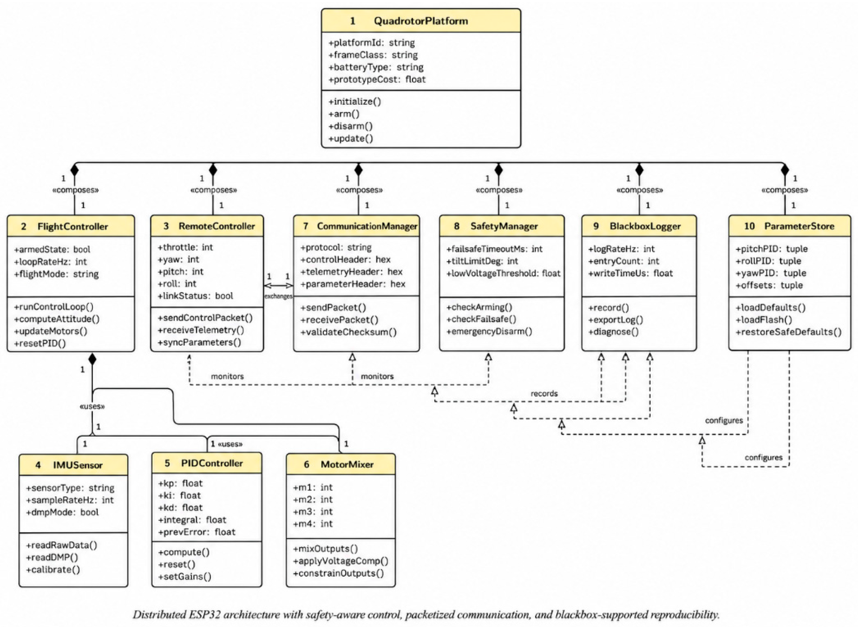
Figure 3.
UML activity diagram of safety-aware flight operation and blackbox-supported diagnosis.
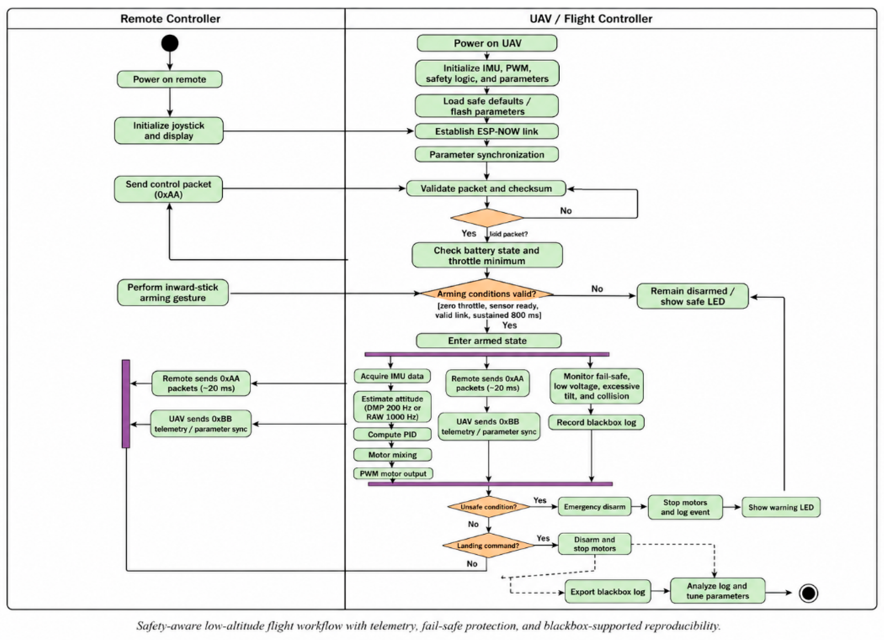
Figure 4.
Experimental performance and blackbox diagnostic results of the proposed ESP32-based quadrotor platform. (a) Hover attitude during a short indoor test. (b) Communication and control timing. (c) Representative motor outputs and battery state. (d) Blackbox diagnostic summary.
Figure 4.
Experimental performance and blackbox diagnostic results of the proposed ESP32-based quadrotor platform. (a) Hover attitude during a short indoor test. (b) Communication and control timing. (c) Representative motor outputs and battery state. (d) Blackbox diagnostic summary.
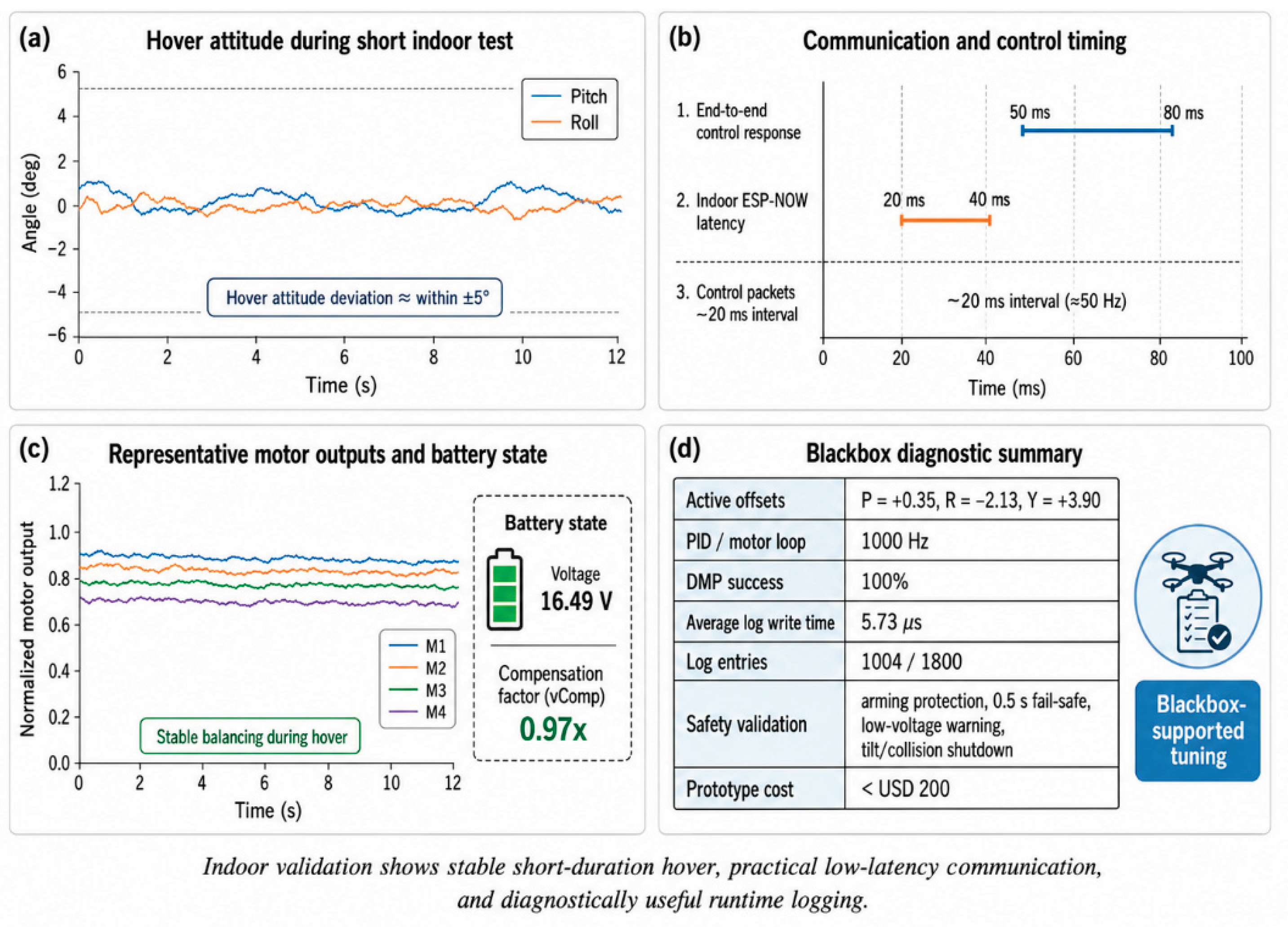

Table 1.
Recommended bill of materials for the proposed ESP32-based quadrotor testbed.
| Category | Component | Specification | Qty. | Role |
| Controller | ESP32 DevKit V1 | Flight MCU and remote MCU | 2 | Embedded processing and wireless communication |
| Sensor | MPU6050/MPU9250 IMU | 6-axis or 9-axis inertial module | 1 | Attitude sensing |
| Actuation | Brushless motors | 800–920 KV large frame or higher KV small frame | 4 | Propulsion |
| Actuation | ESC | 20–30 A electronic speed controller | 4 | Motor driving |
| Propulsion | Propellers | 5-inch or 7-inch depending on prototype | 4 + spares | Lift generation |
| Power | LiPo battery | 3S or 4S pack | 1 | Main power source |
| Power | Voltage divider | ADC interface for battery sensing | 1 | Voltage monitoring |
| Structure | X-frame | Carbon-fiber or nylon quadrotor frame | 1 | Mechanical support |
| Communication | ESP-NOW | Built-in peer-to-peer ESP32 wireless link | 1 set | Control and telemetry |
| Safety | LED indicators | Single- or multi-color state indication | 1 set | Operator warning and state display |
Table 2.
Communication packet types implemented in the proposed platform.
| Header | Direction | Purpose | Payload summary |
| 0xAA | Remote → UAV | Real-time control | Throttle, yaw, pitch, roll, checksum |
| 0xBB | UAV → Remote | Telemetry feedback | Armed state, voltage, signal quality, throttle, corrections |
| 0xCC | Bidirectional | Parameter synchronization | PID gains, offsets, filters, expo, state bits |
Table 3.
Safety-aware control mechanisms embedded in the proposed platform.
| Mechanism | Trigger condition | System response | Safety intent |
| Arming protection | Throttle not at minimum or invalid arming gesture | Remain disarmed; arming accepted only after about 800 ms sustained gesture | Prevent accidental motor activation |
| Communication fail-safe | No valid control packet for about 0.5 s | Safety disarm and PID reset | Prevent stale-command flight |
| ESC calibration isolation | Calibration mode explicitly enabled | Normal flight disabled; warning state entered | Prevent dangerous full-throttle mistakes |
| Low-voltage warning | Battery below threshold | Operator warning and recommended landing | Reduce battery-related risk |
| Remote offline warning | No telemetry return for about 1.5 s | Display offline state and inhibit unsafe operation | Reduce operator confusion after link loss |
| Tilt protection | Pitch or roll exceeds safe angle | Motor shutdown/disarm | Limit crash escalation |
| Collision protection | Abnormal acceleration or nonrecovering response | Motor shutdown/disarm | Reduce post-impact damage |
| Safe default recovery | Parameters invalid or unstable | Load conservative defaults | Recover from unsafe tuning |
Table 4.
Core evaluation metrics and acceptance logic used in the condensed validation study.
| Metric | Operational meaning | Observed range or criterion |
| Hover attitude deviation | Pitch/roll stability during short indoor hover | Approximately within ±5 degrees |
| Control response time | Remote input to motor-output update | Approximately 50–80 ms |
| Wireless latency | Indoor ESP-NOW packet delay | Approximately 20–40 ms |
| Fail-safe response | Link-loss shutdown behavior | Motor output disabled when no command for about 0.5 s |
| Arming reliability | Gesture-based safe activation | Zero throttle plus sustained inward-stick arming logic |
| Logging overhead | Impact of blackbox recording on operation | Low enough to preserve basic real-time control |
| System cost | Budget for reproducible reconstruction | Below approximately USD 200 |
Table 5.
Condensed summary of key experimental findings.
| Aspect | Finding | Interpretation |
| Platform integration | Sensing, actuation, telemetry, safety, and logging all operated on the ESP32-based architecture | The architecture is viable as a compact UAV research testbed |
| Hover stability | Short-duration indoor hover maintained within approximately ±5 degrees in pitch/roll | Adequate for low-altitude validation and teaching use |
| Control responsiveness | End-to-end response around 50–80 ms | Fast enough for manual low-altitude experiments |
| Wireless link | Indoor ESP-NOW latency around 20–40 ms | Suitable for control and telemetry without router infrastructure |
| Safety behavior | Fail-safe, arming protection, and shutdown logic behaved as designed | Safety-aware design materially improves operational confidence |
| Reproducibility | Cost below roughly USD 200 with documented hardware and procedure | Platform can be reconstructed and reused across cohorts or studies |
Table 6.
Example blackbox-assisted diagnostic interpretations used in the tuning workflow.
| Observed pattern | Likely interpretation | Preferred engineering response |
| Persistent drift with low oscillation | Static pitch/roll offset or imbalance | Correct offsets before raising gains |
| Rapid alternating correction around setpoint | Gain too aggressive or derivative filtering insufficient | Reduce or retune PID gains |
| Weak response as voltage declines | Battery sag affecting thrust margin | Inspect compensation factor and battery condition |
| Sudden motor shutdown with packet gap | Communication fail-safe activation | Check link quality and packet timing |
| Uneven motor command saturation | Motor order, thrust mismatch, or frame imbalance | Recheck motor mapping, propellers, and mechanics |
| Repeated unsafe startup denial | Throttle or arming condition invalid | Verify remote neutral state and startup sequence |
Table 7.
Positioning of the proposed platform relative to conventional UAV controller options.
| Criterion | Proposed ESP32 platform | Commercial controller | Large open-source autopilot |
| Primary strength | Transparency and low-cost reproducible experimentation | High integration and polished operation | Extensive autonomy features and ecosystem |
| Firmware accessibility | Direct and lightweight | Usually limited | High but complex |
| Safety logic visibility | Explicit and modifiable | Often abstracted to configuration | Rich but distributed across a large stack |
| Best-fit use case | Laboratory low-altitude validation, education, controller experiments | Operational deployment and convenience | Advanced autonomy and field robotics research |
| Cost barrier | Low | Medium to high | Medium with broader hardware demands |
Disclaimer/Publisher’s Note: The statements, opinions and data contained in all publications are solely those of the individual author(s) and contributor(s) and not of MDPI and/or the editor(s). MDPI and/or the editor(s) disclaim responsibility for any injury to people or property resulting from any ideas, methods, instructions or products referred to in the content. |
© 2026 by the authors. Licensee MDPI, Basel, Switzerland. This article is an open access article distributed under the terms and conditions of the Creative Commons Attribution (CC BY) license (http://creativecommons.org/licenses/by/4.0/).
Copyright: This open access article is published under a Creative Commons CC BY 4.0 license, which permit the free download, distribution, and reuse, provided that the author and preprint are cited in any reuse.