

Submitted:
10 July 2026
Posted:
13 July 2026
You are already at the latest version
Abstract
The goal of the present work is to develop accurate path algorithm and develop software for navigation of mobile robot to reach target point from the starting point avoiding obstacles on the workspace using ultrasonic sensory feedback. After location of obstacles on the workspace is determined by ultrasonic sensor, the Activity Bot will move towards the destination from the starting position. The analyses, techniques and algorithms described in the work are related to any mobile robot, and the program development and experiments described in the work and run by Simple IDE software.
Keywords:
mobile robot
; improved point bug path planning algorithm
; simple IDE software
; ultrasonic sensor
I. Introduction
A mobile robot is a particular kind of robot that is managed by software that uses sensors and other technologies to detect obstacles in its surroundings and move around. Mobile robots [2,10] are able to move around on their own, that is, without the assistance of human operators. Mobility allows mobile robots to execute a wide range of applications with considerably more freedom. Even tasks that are not intended for surroundings can be easily completed by mobile robots. Locomotive mechanisms are used in mobile robots to facilitate movement around their surroundings. The mobile robots are composed of several hardware and software components, such as sensors, actuators, controllers, and control software. To determine the position of objects (obstacles), several types of sensors, such as laser and ultrasonic sensors, are also necessary. Actuators that transform electrical energy into mechanical energy are most frequently found in mobile robots.
Combining physical components with artificial intelligence (AI), the mobile robots do their tasks. The mobile robots’[3] body parts are their wheels, legs, and tracks. Traditionally, motion planning [4,12] has made extensive use of methods such as visibility graphs, cell decomposition, and potential fields. These classical methods, however, have several drawbacks, such as high temporal complexity in high dimensions and issues with becoming caught in local minima. For robot motion planning, soft computing techniques like fuzzy logic and biologically inspired approaches like genetic algorithms [11], artificial neural networks[13], ant colony optimization [6,14], and others have been widely used.
II. Problem Formulation and Proposal
In the present work, instead of choosing the sudden point which is closest from the target (goal), i.e., which is at a shortest distance from goal, as the next point to move, the sudden point which provides the shortest sub-path towards goal, is chosen as the next point to move. The main objective is to choose the path having the minimum sum of subpaths which are leading to the destination. But by the definition in an unknown environment only a limited part of environment is known. The robot knows only a subset of sudden points. The computations are done before reaching the sudden point. As the robot reaches before the obstacle, with the help of a simple range sensor it can able to navigate sudden points on both side of the obstacle. It then calculates the total path length via the sudden points and the principle of the modified point bug algorithm is to use the Euclidian distance to choose the shortest path. A. Description of the Algorithm:
The new and improved Point Bug algorithm [1,5,8,9] calculates the length of all the sub-paths [C, S0] and [S0, T], [C, S1] and [S1, T], [C, S2] and [S2, T], [C, S3] and [S3, T], [C, S4] and [S4, T] for Figure 1. The robot will then choose point S2 (instead of S3) since the path length is minimal. So here the selected path is C-S2-T. The algorithm will tests all accessible sudden points then calculate the total path length and finally choose the point which provides shortest path to the target after the robot reaches at any sudden point which will be treated as current shortest point (C). The S2 point will be added to the current shortest point (C). When S2 is already selected, it will be added to the rejected set (R) and ignored afterwards. If no sudden point is detected further, the robot turns back and continues with the next one after adding current point to the rejected set (R). Thus the algorithm provides guarantee of testing of all accessible sudden point and termination of the algorithm is assured.
III. Proposed Method
A. Program development for path planning of mobile robot based on the improved point bug algorithm: A program has been developed in Propeller C language for IDE software for path planning of the Activity-Bot mobile robot using Ping range sensor (capable of 180° rotation) based on the modified point bug algorithm. The developed program has been used to move the mobile robot from a start to a goal point by avoiding obstacles coming across its path. The coordinates of the start and goal points are entered as variables to execute the program in different layouts of the workspace. The robot is kept parallel to the x-axis at the start position. The Euclidean distance and orientation of goal point from start point is calculated. The robot rotates towards goal, and starts moving towards it. The distance of the nearest object (obstacle), as received by the range sensor, is continuously monitored and the robot moves towards the goal in small steps (taken as 3-ticks = 9.75 mm) until an obstacle is detected within a specified distance (taken as 30 cm) from the range sensor. The coordinates of the current location are calculated using trigonometric relation and formulas of sine and cosine. After detection of an obstacle the range sensor starts searching for the sudden points on both sides by rotating the sensor[7]. The sudden point is taken as a point where the distance measured by the range sensor increases by an amount (taken as 20 cm) such that there is enough space for the mobile robot to go through. The angle of sensor rotation is noted and recorded for determining the angular rotation of the sudden point.
But the sensor is further rotated in the same direction to check whether no other obstacle is present within a specified angle (taken as 30° at a distance of 30 cm) such that there is enough space for the Activity-Bot mobile robot to go through. If any other obstacle is detected within this angle, the process is repeated and the sudden point is modified, and the corresponding angle of sensor rotation, is also modified. If no sudden point is obtained within 90° of rotation, a message is shown to indicate that it is not possible to move to that direction. Now, when a hollow tube is attached on the ultrasonic receiver to reduce the angular spread of the ultrasonic waves, it is observed that the ultrasonic sensor receives reflected waves from an edge of an obstacle at angular deviation(spread) of 13° or 14°. Now after the sudden point on both right and left sides are detected, the location of the modified sudden point on both sides are determined considering the actual dimension of the mobile robot and according to the modification done for the angle of rotation and distance. Then the distance from the current point to the modified sudden point and the modified sudden point to target have been calculated and added for both sides for finding the total distance to transverse further to reach the goal point (for both the sudden points). The robot then ‘chooses’ to move towards the location of the modified sudden point which provides the shorter path. Then the mobile robot rotates towards this modified sudden point by properly calculating the angle of rotation required for this, and moves to this location by properly calculating the distance. After reaching the selected modified sudden point, the robot again rotates towards the target by turning through a properly calculated angle, and again goes towards the goal in steps as it did at the beginning. The whole process is repeated until the robot reaches its goal, or a situation is reached when no path can be found.
b. Program Flow Chart of Improved Point Bug Algorithm:
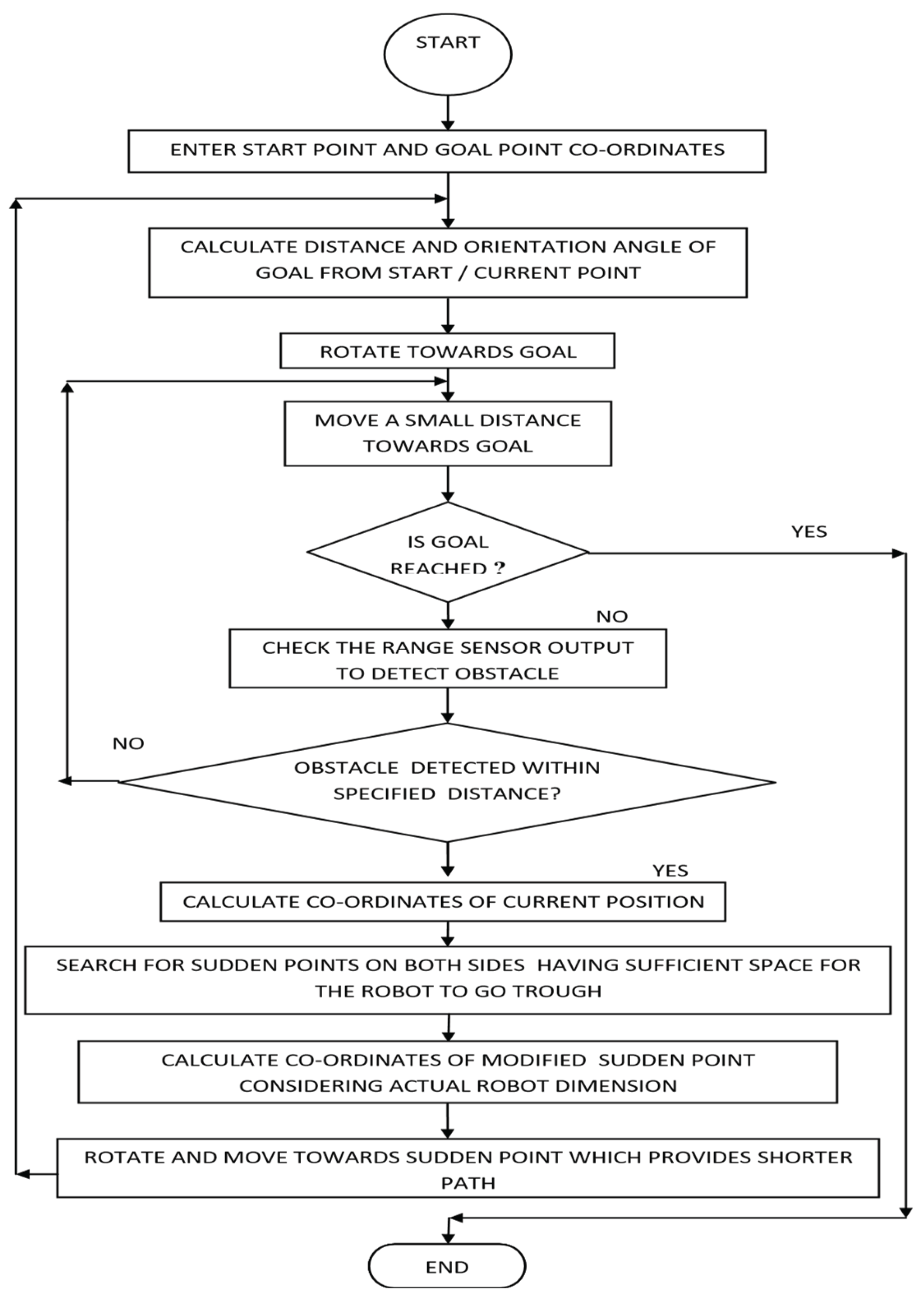
The simple flowchart of the process is shown in Figure 2
Step1: To set up an arrangement for the workspace consisting of Activity-Bot robot fitted with an ultrasonic range sensor and obstacles on a suitable worktable having a marked boundary.
Step2: To mount the Ping ultrasonic range sensor on the Activity-Bot mobile robot system, and make necessary hardware connections to connect it to the propeller microcontroller through its input-output port (pins). To make necessary arrangements to be made to rotate the Ping sensor through 180° by a servo motor fitted to the Activity-Bot mobile robot system.
Step3: To make necessary arrangement to re-oriented the Ping sensor so that the axes of its emitter and receiver are in the same vertical plane for getting reflected waves symmetrically from both sides of any object, instead of their original orientation where the axes of the emitter and receiver are in the same horizontal plane.
Step4: To make an arrangement to minimize the angular spread of ultrasonic waves for obtaining more accurate sudden point location of the obstacles in the path of the robot towards goal by attaching a hollow tube on the receiver of the Ping sensor.
Step5: To develop a simplified algorithm based on point bug algorithm with necessary modification for considering the actual dimension of the Activity-Bot mobile robot for moving the mobile robot from a start point to a target point by detecting and avoiding obstacles, if any, along its path towards goal.
Step6: To develop a program in Propeller C language using Simple IDE software for the Activity-Bot mobile robot for producing necessary movements of the robot in presence of static obstacles for moving from a starting point to a target point using an improved form of Point Bug algorithm, as mentioned in (e).
Step7: To run the program for different layout of workspace for testing the usefulness of the algorithm.
IV. Results and Analysis
The developed C program has been run for moving the Activity-Bot robot from its starting point to the goal point by detecting any obstacle using Ping sensor. The angular position of the sudden point is obtained from servo motor rotation on which the sensor is mounted. While advancing towards goal the range sensor continuously senses the distance to detect any obstacle within a specified distance (taken as 30 cm). On detection of obstacle, scanning operation is carried out by simply rotating the servo motor attached to the sensor for determining the sudden points on both sides. On reaching the sudden point, the program again calculates the angle and distance of goal from current point, then rotates and starts moving towards goal. The program will continue till the robot reaches its target. In this way the robot moves in an unknown environment by avoiding obstacle in near optimal path. The developed program has been run successfully for different layouts of the workspace with different positions of the obstacles and goal point. But it is not to achieve a fully optimal path. As the range sensor checks only the nearest obstacle along its path towards goal, only a portion of the workspace is ‘sensed’ by the sensor. So, there is a possibility of having other obstacles in between the selected sudden point and the destination, for which the information about their position, etc. is not known. This may further increase the path length. The photographic views of robot position and orientation at some important positions along its path towards goal for the same layout are shown in Figure 3 to Figure 7.
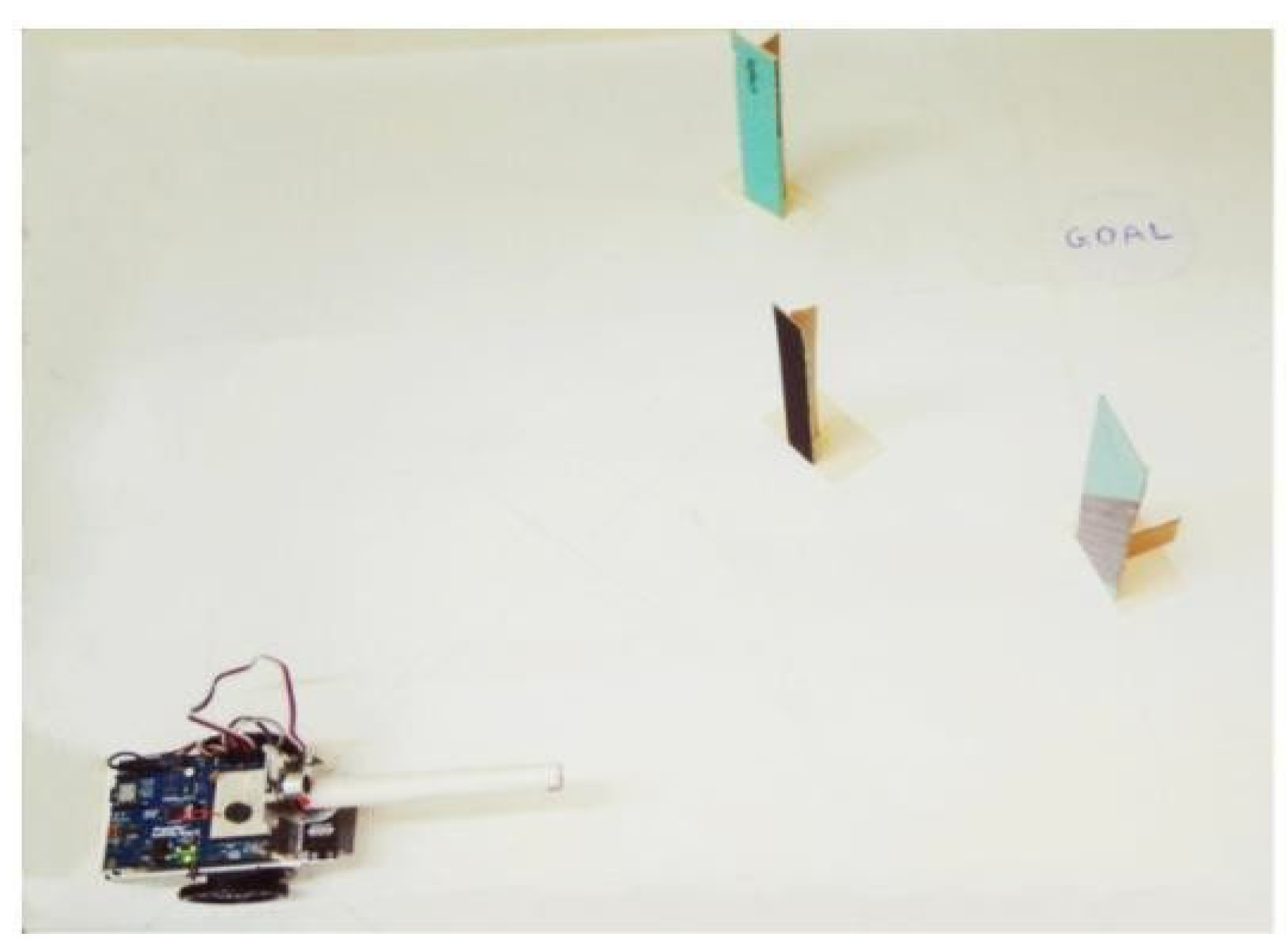
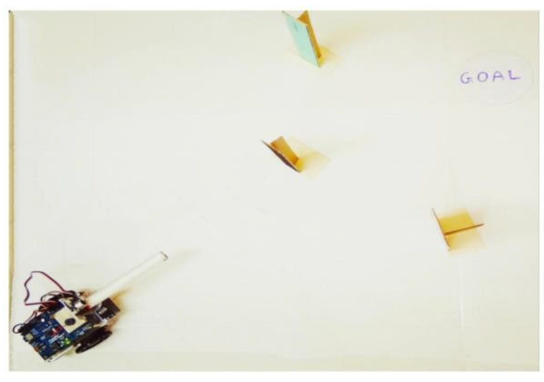
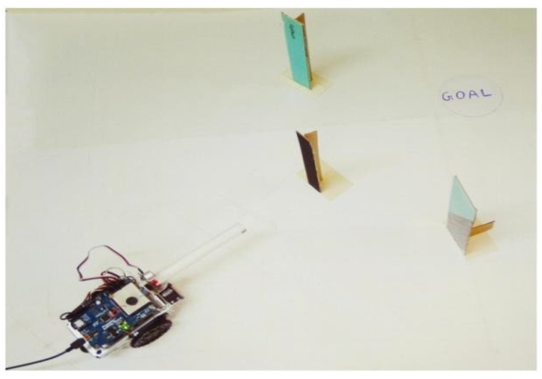
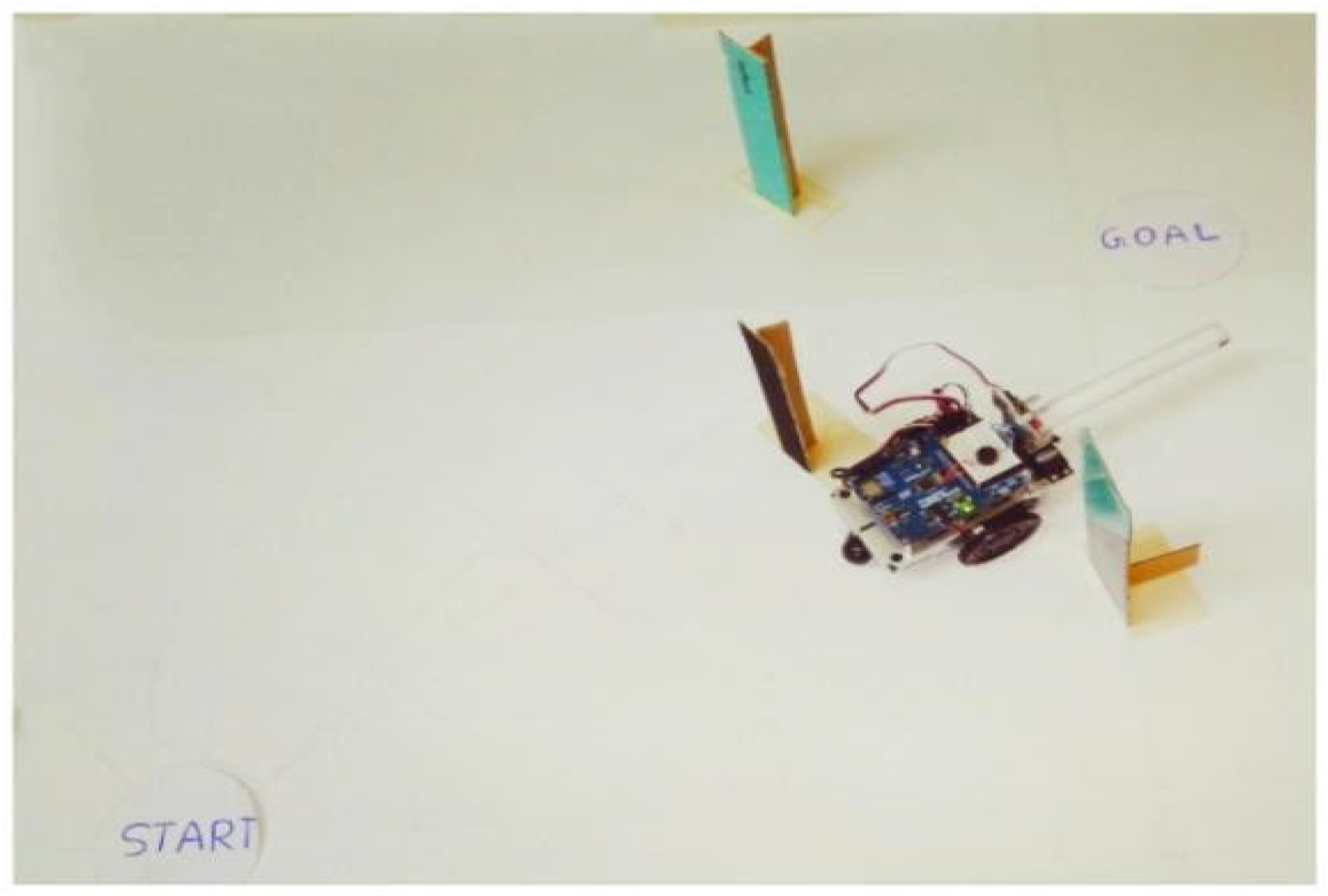
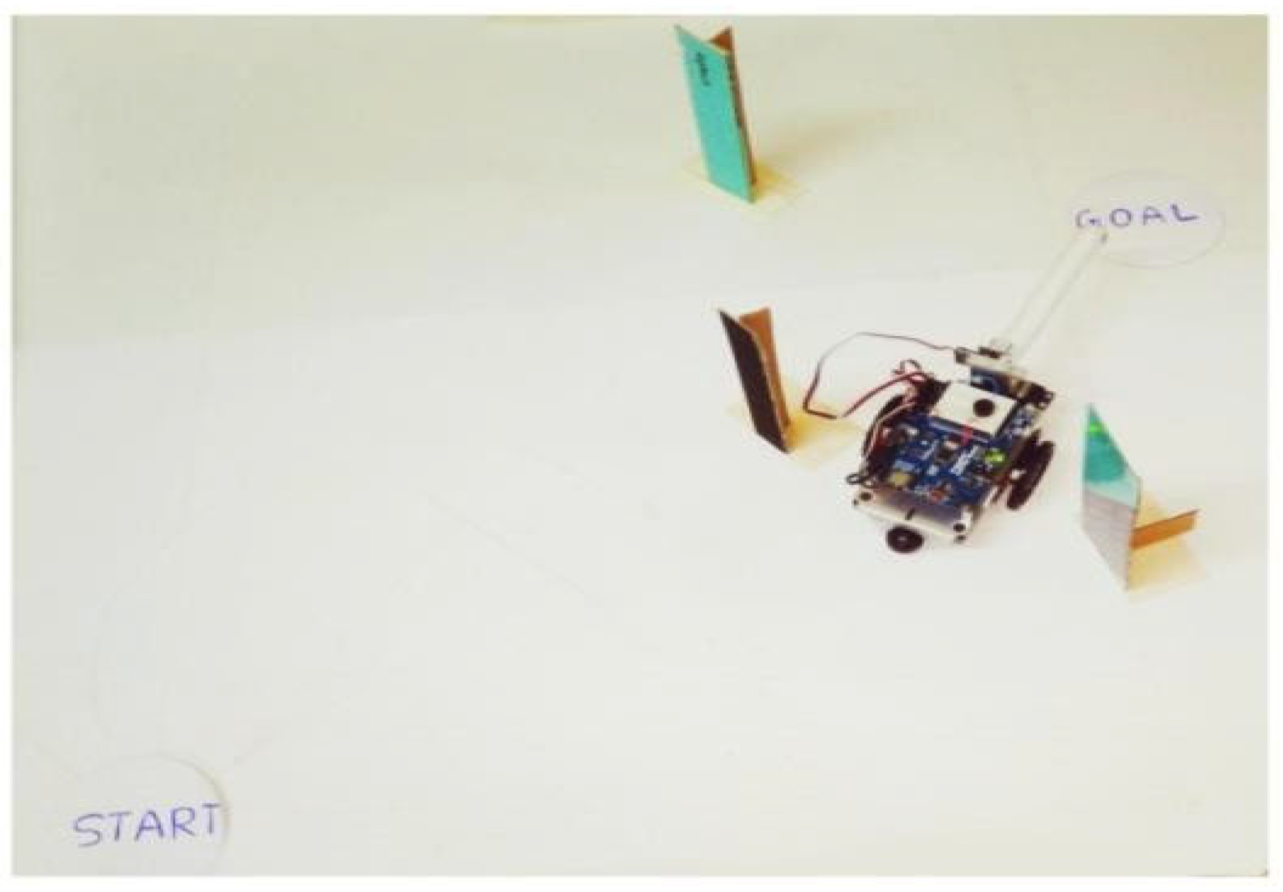
Figure 3.
Photographic View of one Workspace Layout Consisting of Mobile Robot and Obstacles at the Start Position.
Figure 3.
Photographic View of one Workspace Layout Consisting of Mobile Robot and Obstacles at the Start Position.
Figure 4.
Photographic View of Mobile Robot Rotating towards Goal at Start Position.
Figure 5.
Photographic View of Mobile Robot Position When an Obstacle is detected.
Figure 6.
Photographic View of Mobile Robot Position Reaching a Sudden Point after an Obstacle is Detected.
Figure 6.
Photographic View of Mobile Robot Position Reaching a Sudden Point after an Obstacle is Detected.
Figure 7.
Photographic View of Mobile Robot Position Rotating towards Goal after reaching a Sudden Point.
Figure 7.
Photographic View of Mobile Robot Position Rotating towards Goal after reaching a Sudden Point.
V. Conclusions
Various algorithms of different path planning techniques have been studied thoroughly including Bug group of algorithms, where Point Bug and some other modified Bug algorithms have been found suitable in most cases. Point Bug algorithm has some limitations in finding optimal path because minimizing the angular deviation does not always guarantee shortest path. Some improved algorithms have also been studied which overcomes the deficiencies of Point Bug algorithm. This algorithm is an improved algorithm as compared to Point Bug algorithm and is based on the Point Bug algorithm. This algorithm finds the near optimal path by adding the sub-paths lengths from current point to sudden point and from sudden point to target point and selecting the shorter sub-path. The sensor output helps in detecting any obstacle present along the path of the robot while travelling the distance in a straight line.
Most of the existing path planning algorithms consider mobile robot as a point source and simulation results are available and a very few real robot experimentations of the algorithms have been performed. In the present project robot dimensions have been taken into account while developing the program to prove the effectiveness of the algorithm in real life situation. Here some modifications have been made in the algorithm for the sudden points. An arrangement has been made for setting up the workspace consisting of an Activity-Bot mobile robot and multiple obstacles. The range sensor has been mounted on the 180-degree rotating servo motor and it has been used for scanning both ends of the obstacle for sudden point detection. Modifications have been done to minimize the angular spread of the reflected ultrasonic waves for accurate angle and distance measurement for the sudden points. A program in
Propeller C, based on improved Point Bug algorithm for navigating the robot from start to goal position in presence of static obstacles, considering robot dimensions, has been developed using Simple IDE software. The developed program has been run successfully for different workspace layouts and thereby proving the usefulness of the path planning algorithm in industrial application.
VI. Future Work
Future scope of the present work includes experimentation of the algorithm and program for more varieties of workspace layouts with a more number of obstacles and also in presence of dynamic (moving) obstacles by modifying the algorithm and developing the program accordingly. The ultrasonic range sensors may also be replaced by laser range sensor for the sudden points more accurately, thus avoiding the problem of angular spread of ultrasonic sensor.
References
- Athanasios Lentzas, Dimitris Vrakas LadyBug, “ Intensity based Localization Bug Algorithm”, 978-1-7281-89567/20/$31.00 ©2020 IEEE.
- P. Victerpaul , D. Saravanan , S. Janakiraman , J. Pradeep, “Path Planning of Autonomous Mobile Robots: A Survey and Comparison”, Journal of Advanced Research in Dynamical and Control Systems, Vol. 9. Sp– 12 / 2017. 3. Zohaib, M., Pasha, M., Riaz, R.A., Javaid, N., Ilahi, M., & Khan, R.D, “Control Strategies for Mobile Robot with.
- Obstacle Avoidance” COMSATS Institute of Information Technology, Islamabad, Pakistan. CoRR, abs/1306.1144, 2013. 4. Buniyamin N., Wan Ngah W.A.J., Sariff N., Mohamad Z., “ A Simple Local Path Planning Algorithm for.
- Autonomous Mobile Robots”, International Journal of Systems Applications, Engineering & Development, Issue 2, Volume 5, 2011.
- Meddah, F., & Dib, L., “E-Bug: New Bug Path-Planning Algorithm for Autonomous Robot in Unknown Environment”, Proceedings of the International Conference on Intelligent Information Processing, Security and Advanced Communication, 2015, 1-8. [CrossRef]
- Jun-Hao Liang, Ching-Hung Lee, “Efficient Collision-Free Path-Planning Of Multiple Mobile Robots System Using Efficient Artificial Bee Colony Algorithm,” Advances In Engineering Software 79, 2015.
- N. Nirmal Singh, Avishek Chatterjee, Amitava Chatterjee, Anjan Rakshit, “A Two-Layered Subgoal Based Mobile Robot Navigation Algorithm with Vision System and IR Sensors” Electrical Engineering Department, Jadavpur University, Kolkata 700 032, India, Accepted 17 December 2010, Available online 30 December 2010.
- Mr. Subir Kumar Das, Dr. Ajoy Kumar Dutta, Mr. Subir Kumar Debnath, “Operative Critical Point Bug Algorithm – Local Path Planning of Mobile Robot Avoiding Obstacles, Indonesian Journal of Electrical Engineering and Computer Science, Vol.18, No.3, June 2020, pp 1646 -1656.
- B. Margaret Devi, Prabakar S, “Dynamic Point Bug Algorithm For Robot Navigation”, International Journal of Scientific & Engineering Research, Volume 4, Issue 4, April-2013, Pages 1276-1279.
- Rami Al-Jarrah, Mohammad Al-Jarrah, and Hubert Roth, “A Novel Edge Detection Algorithm for Mobile Robot Path Planning”, Hindawi Journal of Robotics, Volume 2018, Article ID 1969834.
- Chaymaa Laminia, Said Benhlimab, Ali Elbekri, “Genetic Algorithm Based Approach for Autonomous Mobile Robot Path Planning”, First International Conference on Intelligent Computing in Data Sciences, 2018, Published by Elsevier B.V.
- Li G, Chou W. “Path Planning for Mobile Robot using Self-Adaptive Learning Particle Swarm Optimization”, Science China Information Sciences, May 2018.
- Haj Darwish, Ahmed, Abdulkader Joukhadar, and Mariam Kashkash, “Using the Bees Algorithm for Wheeled Mobile Robot Path Planning in an Indoor Dynamic Environment”, Cogent Engineering, 2018.
- Akka, Khaled, and Farid Khaber. “Mobile Robot Path Planning using an Improved Ant Colony Optimization”, International Journal of Advanced Robotic Systems 15.3, May 2018.
Figure 1.
The strategy of modified point bug Algorithm.
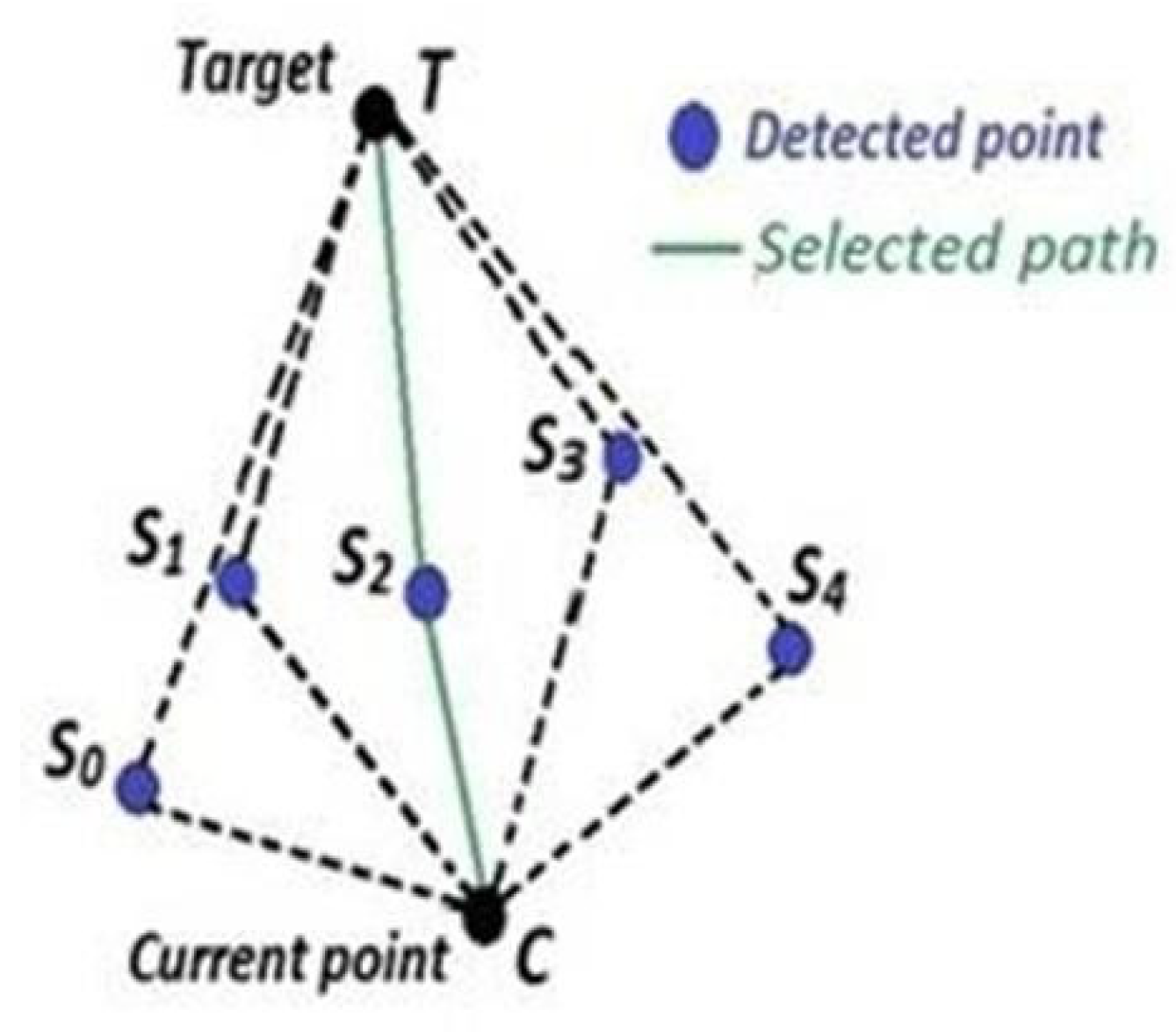
Figure 2.
Flowchart of the Developed Program C. Working Methods: The main methods of the present work are:.
Figure 2.
Flowchart of the Developed Program C. Working Methods: The main methods of the present work are:.
Disclaimer/Publisher’s Note: The statements, opinions and data contained in all publications are solely those of the individual author(s) and contributor(s) and not of MDPI and/or the editor(s). MDPI and/or the editor(s) disclaim responsibility for any injury to people or property resulting from any ideas, methods, instructions or products referred to in the content. |
© 2026 by the authors. Licensee MDPI, Basel, Switzerland. This article is an open access article distributed under the terms and conditions of the Creative Commons Attribution (CC BY) license (http://creativecommons.org/licenses/by/4.0/).
Copyright: This open access article is published under a Creative Commons CC BY 4.0 license, which permit the free download, distribution, and reuse, provided that the author and preprint are cited in any reuse.